Copyright c 2006 IEEE. Reprinted from V. V. S. Nagesh Polu, Bruce G. Colpitts and Brent R. Petersen, “Symbol-wavelength MMSE gain in a multi-antenna UWB system,” Proceedings of the 4 th Annual Com- munication Networks and Services Research Conference (CNSR 2006), vol. 1, (Monc- ton, NB, Canada), pp. 95-99, May 24-25, 2006. This material is posted here with permission of the IEEE. Internal or personal use of this material is permitted. However, permission to reprint/republish this material for advertising or promotional purposes or for creating new collective works for resale or redistribution must be obtained from the IEEE by sending a blank email message to [email protected]. By choosing to view this document, you agree to all provisions of the copyright laws protecting it. CNSR 2006 was technically co-sponsored by the IEEE Communications Society and the ACM. This paper received the Conference Best Paper Award.
This material is posted here with permission of the IEEE. Internal or personal useof this material is permitted. However, permission to reprint/republish this materialfor advertising or promotional purposes or for creating new collective works for resaleor redistribution must be obtained from the IEEE by sending a blank email messageto [email protected].
By choosing to view this document, you agree to all provisions of the copyrightlaws protecting it.
CNSR 2006 was technically co-sponsored by the IEEE Communications Societyand the ACM.
This paper received the Conference Best Paper Award.
Proceedings of 4 thAnnual Communication Networks and Services Research Conference (CNSR 2006),(Moncton, NB, Canada), May 24-25, 2006.
Symbol-wavelength MMSE gain in a multi-antenna UWB system
V. V. S. Nagesh Polu, Bruce G. Colpitts, and Brent R. PetersenUniversity of New Brunswick
Department of Electrical and Computer EngineeringFredericton, NB, Canada - E3B 5A3
Ultra wideband (UWB) technology has the potentialto provide high speed data services. These speeds can begreatly increased by using multiple input multiple out-put (MIMO) techniques. Multiple antennas are usedto achieve spatial diversity and these antenna elementsmust be separated properly to have uncorrelated com-munication signals. The separation can be on the scaleof a symbol wavelength ([speed of light]/[symbol rate]).We have designed a printed circular disc monopole andmeasured the UWB radio channel. Finally, we used themeasurements to show the minimum mean squared er-ror (MMSE) performance gain which occurs when thereceiver antennas are separated on the scale of a symbolwavelength.
Keywords: MIMO systems, adaptive equalizers, an-tenna measurements
1 Introduction
UWB technology seems to be an efficient solution forthe ultra high-speed data services (i.e. speeds up to 480Mbps) in wireless personal area network (WPAN) envi-ronments (i.e. in ranges of ≈ 10 m). This is because ofits low cost and very simple architecture. Recently theFederal Communication Commission (FCC) allocateda very wide spectrum of 7.5 GHz (i.e. from 3.1 GHzto 10.6 GHz) for UWB applications. UWB technologyuses two different modulation techniques to cover en-tire UWB spectrum, one technique is Impulse-UWB,which uses a very short duration pulses to transmitdata over a large bandwidth and the other is a multi-carrier UWB technique [1]. The FCC defines UWB as asignal with either a fractional bandwidth of 20 percentof the center frequency or a minimum of 500 MHz [1].
Important recent work shows the dependence of cor-related interference on antenna element spacing [2].
The authors defined a parameter called chiplength([speed of light]/[chip rate]), which can be used to sepa-rate antennas in a multi antenna system to have uncor-related interference at the antenna branches. Similarwork describes the separation of the receiver anten-nas on the scale of a signalling wavelength to achievespatial multiplexing [3]. Chamchoy et al. showed thatthere is a high degree of correlation between the chan-nels when the antennas are separated based on halfthe carrier wavelength [4]. In this paper we investi-gated the MMSE performance of an UWB system in aline of sight (LoS) scenario, when the receiver antennasare separated on the scale of a symbol wavelength (λT )to have uncorrelated communication signals at the re-ceiver. The uncorrelation is showed in terms of MMSEgain with increasing separation.
This paper is organized as follows: section 2 de-scribes the system model, section 3 is about the de-signed antenna for UWB applications, section 4 isabout UWB channel measurements, section 5 containsthe simulation results of the MMSE equalizer, followedby conclusions and references [5].
2 Two-by-Two System and ChannelModel
The two-by-two system and channel model will bediscussed in this section.
2.1 Channel Model
The two-by-two baseband channel model consists offour baseband impulse channels between two users andtwo receive antennas and it is given by
h(t) =(
h11(t) h12(t)h21(t) h22(t)
)(1)
95
and its Fourier transform representation is
H(f) =(
H11(f) H12(f)H21(f) H22(f)
). (2)
2.2 System Model
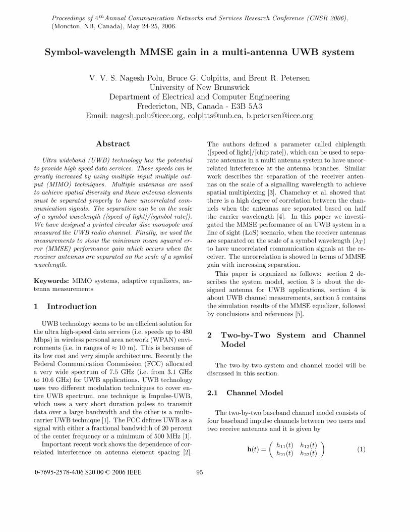
The two-by-two system model is shown in the Fig-ure 1. In this paper we consider the uplink of the UWBsystem with two receive antennas and two simultane-ous users [6]. The data is a zero-mean random processand is passed through a pulse shaping filter for trans-mission into the channel. The signal transmitted fromuser j is of the form
sj(t) =∞∑
n=−∞dj(n) p(t − nT ) (3)
where j represents the user number, either 1 or 2, dj(n)is binary data which takes values of {−1, 1} and thepulse shaping filter p(t) is a raised cosine type with100% excess bandwidth. Finally the data signal fromthe users is transmitted through a baseband channel,whose impulse response is given by h(t) and its equiv-alent frequency domain representation is H(f). The
WirelessChannels
nd1p(t)
)(1 ts
)(2 ts
thij
nd 2~nT
td 2ˆ
nd1~nT
td1ˆ
t2r
tr1
w(t)
nd 2p(t)
Figure 1. Two-by-Two system and channel model
signal at the receiving antenna is the convolution ofthe transmitted signal and the baseband channel im-pulse response plus noise and is given by
r(t) = h(t) ⊗ s(t) + η(t) (4)
where ⊗ denotes matrix convolution and η(t) is a zero-mean additive white Gaussian noise. The received sig-nal at the antenna is passed through a receiving filterwhose impulse response is w(t). The output of the re-ceiving filter is the convolution of r(t) and w(t) (i.e.w(t) ⊗ r(t)). The receiving filter coefficients are up-dated based on the MMSE criterion determined dur-ing training. The received signal r(t) and the receiving
filter w(t) are given by
r(t) =(
r1(t)r2(t)
)(5)
w(t) =(
w11(t) w12(t)w21(t) w22(t)
). (6)
3 Antenna Design
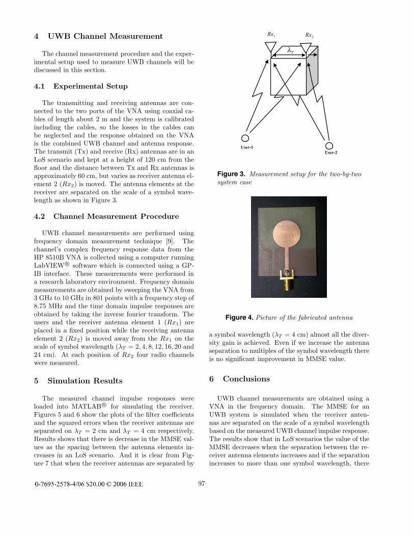
In order to make UWB channel measurements weneed antennas that have a very wide impedance band-width and near omni-directional characteristics for theentire UWB spectrum. We searched for small UWBantennas which have the potential for use in UWB de-vices [7, 8]. Finally we simulated and fabricated theprinted circular disc monopole antenna specified byLiang et al. [7]. The parameters specified are modifiedslightly because we used a substrate with a differentthickness. The length and width of the designed an-tenna is 50 mm and 42 mm respectively. The antennasimulations were performed using CST Microwave Stu-dio and antennas were fabricated on an FR-4 substratewhose dielectric constant is 4.2. A picture of the fabri-cated antenna is shown in Figure 4. The antennas weremeasured using an HP 8510B Vector Network Analyzer(VNA) and the SWR plot of the measured and simu-lated curves is shown in Figure 2. It is clear from Fig-ure 2 that the designed antenna has an SWR of 2.2:1or better in the specified band.
2 3 4 5 6 7 8 9 10 11
x 109
1
2
3
4
5
6
7
Frequency (Hz)
SW
R
MeasuredSimulated
Figure 2. Comparison of measured and simulatedSWR
96
4 UWB Channel Measurement
The channel measurement procedure and the exper-imental setup used to measure UWB channels will bediscussed in this section.
4.1 Experimental Setup
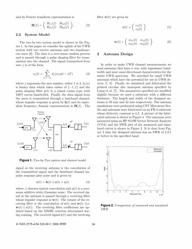
The transmitting and receiving antennas are con-nected to the two ports of the VNA using coaxial ca-bles of length about 2 m and the system is calibratedincluding the cables, so the losses in the cables canbe neglected and the response obtained on the VNAis the combined UWB channel and antenna response.The transmit (Tx) and receive (Rx) antennas are in anLoS scenario and kept at a height of 120 cm from thefloor and the distance between Tx and Rx antennas isapproximately 60 cm, but varies as receiver antenna el-ement 2 (Rx2) is moved. The antenna elements at thereceiver are separated on the scale of a symbol wave-length as shown in Figure 3.
Figure 3. Measurement setup for the two-by-twosystem case
Figure 4. Picture of the fabricated antenna
a symbol wavelength (λT = 4 cm) almost all the diver-sity gain is achieved. Even if we increase the antennaseparation to multiples of the symbol wavelength thereis no significant improvement in MMSE value.
6 Conclusions
UWB channel measurements are obtained using aVNA in the frequency domain. The MMSE for anUWB system is simulated when the receiver anten-nas are separated on the scale of a symbol wavelengthbased on the measured UWB channel impulse response.The results show that in LoS scenarios the value of theMMSE decreases when the separation between the re-ceiver antenna elements increases and if the separationincreases to more than one symbol wavelength, there
97
0 200 400 600 8000
0.5
1
|w1
1|2
Index, i, (−)
Overall MSE after convergence = −11.2 (dB)
0 200 400 600 8000
1
2
|w1
2|2
Index, i, (−)
0 200 400 600 8000
0.5
1
|w2
1|2
Index, i, (−)0 200 400 600 800
0
1
2
|w2
2|2
Index, i, (−)
2 4 6 8 10 12
x 104
−40
−20
0
10
* lo
g1
0 (
SE
1)
Time, n, (−)2 4 6 8 10 12
x 104
−40
−20
0
10
* lo
g1
0 (
SE
2)
Time, n, (−)
Figure 5. Filter coefficients and Squared errorplots for λT = 2 cm
is no significant improvement in MMSE.
7 Acknowledgements
This research work was funded by Atlantic Innova-tion Fund and by Aliant our industrial partner.
References
[1] J. H. Reed, An Introduction to Ultra WidebandCommunication Systems. Upper Saddle River, NewJersey, USA: Prentice Hall PTR, first ed., 2005.
[2] H. Yanikomeroglu and E. S. Sousa, “Antenna gainagainst interference in CDMA macrodiversity sys-tems,” IEEE Transactions on Communications,vol. 50, pp. 1356–1371, Aug. 2002.
[3] G. Zhu, B. R. Petersen, and B. G. Colpitts, “Sig-nalling wavelength in an antenna array for space-time wireless over los channels,” in Proceedings ofthe 3rd Annual Communications Networks Servicesand Research Conference (CNSR 2005), vol. 1,(Halifax, NS, Canada), pp. 69–73, May 16-18, 2005.
[4] M. Chamchoy, S. Promwong, P. Tangtisanon, andJ.-I. Takada, “Spatial correlation properties of mul-tiantenna UWB systems for in-home scenarios,”
0 200 400 600 8000
1
2
|w1
1|2
Index, i, (−)
Overall MSE after convergence = −16.1 (dB)
0 200 400 600 8000
1
2
|w1
2|2
Index, i, (−)
0 200 400 600 8000
1
2
|w2
1|2
Index, i, (−)0 200 400 600 800
0
1
2
|w2
2|2
Index, i, (−)
2 4 6 8 10 12
x 104
−40
−20
0
10
* lo
g1
0 (
SE
1)
Time, n, (−)2 4 6 8 10 12
x 104
−40
−20
0
10
* lo
g1
0 (
SE
2)
Time, n, (−)
Figure 6. Filter coefficients and Squared errorplots for λT = 4 cm
0 5 10 15 20 25−17
−16
−15
−14
−13
−12
−11
Rx Antenna inter element spacing d(cm)
MS
E v
alu
e o
bta
ined (
dB
)
Figure 7. MSE Vs λT
in IEEE International Symposium on Communi-cations and Information Technology 2004 (ISCIT2004), vol. 2, (Sapporo, Japan), pp. 1029–1032,Oct. 26-29 2004.
[5] G. K. Zhu, “On the signalling length in digital wire-less communications,” MScE Thesis, University ofNew Brunswick, Fredericton, Canada, 2005.
[6] N. Amitay and J. Salz, “Linear equalization theoryin digital transmission over dually polarized fading
98
radio channels,” AT&T Tech. J., vol. 63, pp. 2215–2259, Dec. 1984.
[7] J. Liang, C. C. Chiau, X. Chen, and C. G. Parini,“Printed circular disc monopole antenna for ultrawideband applications,” IEEE Electronics Letters,vol. 40, pp. 1246–1247, Sept. 2004.
[8] J. Powell and A. Chandrakasan, “Differential andsingle ended elliptical antennas for 3.1-10.6 GHz ul-tra wideband communication,” in IEEE Antennasand Propagation Society International Symposium,vol. 3, pp. 2935–2938, Jun. 2004.
[9] T. S. Rappaport, Wireless Communications. UpperSaddle River, New Jersey, USA: Prentice Hall PTR,1996.