98
EPTCS 111 Proceedings of the Eighth Workshop on Model-Based Testing Rome, Italy, 17th March 2013 Edited by: Alexander K. Petrenko and Holger Schlingloff

EPTCS 111
Proceedings of the
Eighth Workshop on
Model-Based TestingRome, Italy, 17th March 2013
Edited by: Alexander K. Petrenko and Holger Schlingloff

Published: 2nd March 2013DOI: 10.4204/EPTCS.111ISSN: 2075-2180Open Publishing Association
Table of Contents
Preface . . . . . . . . . . . . . . . . . . . . . . . . . . . . . . . . . . . . . . . . . . . .. . . . . . . . . . . . . . . . . . . . . . . . . . . . . . . . . . . . . . . . 1Alexander K. Petrenko and Holger Schlingloff
Invited Talk: Industrial-Strength Model-Based Testing - State of the Artand Current Challenges . . 3Jan Peleska
Industrial Presentation: Model-Based testing for LTE Radio Base Station . . . . . . . . . . .. . . . . . . . . . . 29Olga Grinchtein
Industrial Presentation: Towards the Usage of MBT at ETSI . . . . . . . . . . . . . . . . . . . . . . . . .. . . . . . . . . 30Jens Grabowski, Victor Kuliamin, Alain-Georges Vouffo Feudjio, Antal Wu-Hen-Chang andMilan Zoric
Testing Java implementations of algebraic specifications .. . . . . . . . . . . . . . . . . . . . . . . . . . . . . . . . . . . . . . 35Isabel Nunes and Filipe Luís
Decomposability in Input Output Conformance Testing . . . . .. . . . . . . . . . . . . . . . . . . . . . . . . . . . . . . . . . . 51Neda Noroozi, Mohammad Reza Mousavi and Tim A.C. Willemse
Runtime Verification Based on Executable Models: On-the-Fly Matching of Timed Traces . . . . . . . . 67Mikhail Chupilko and Alexander Kamkin
Top-Down and Bottom-Up Approach for Model-Based Testing ofProduct Lines . . . . . . . . . . . . . . . . . 82Stephan Weißleder and Hartmut Lackner


1
Preface
This volume contains the proceedings of the Eighth Workshopon Model-Based Testing (MBT 2013),which was held in Rome on March 17, 2013 as a satellite workshop of the European Joint Conferenceson Theory and Practice of Software (ETAPS 2013).
The first workshop on Model-Based Testing (MBT) in this series took place in 2004, in Barcelona. Atthat time model-based testing already had become a hot topic, but MBT 2004 was the first event devotedexclusively to this domain. Since that time the area has generated enormous scientific and industrialinterest, and today there are several other workshops and conferences on software and hardware designand quality assurance covering also model based testing. For example, this year ETSI organizes theUCAAT (User Conference on Advanced Automated Testing) witha focus on ”model-based testing inthe testing ecosystem”. Still, the MBT series of workshops offers a unique opportunity to share newtechnological and foundational ideas particular in this area, and to bring together researchers and usersof model-based testing to discuss the state of the theory, applications, tools, and industrialization.
Model-based testing has become one of the most powerful system analysis methods, where the rangeof possible applications is still growing. Currently, we see the following main directions of MBT devel-opment.
• Integration of model-based testing techniques with various other analysis techniques; in particular,integration with formal development methods and verification tools;
• Application of the technology in the certification of safety-critical systems (this includes establish-ing acknowledged coverage criteria and specification-based test oracles);
• Use of new notations and new kinds of modeling formalisms along with the elaboration of ap-proaches based on usual programming languages and specialized libraries;
• Integration of model-based testing into continuous development processes and environments (e.g.,for software product lines).
The invited talk and paper of Jan Peleska in this volume givesa nice survey of current challenges.Furthermore, the submitted contributions, selected by theprogram committee, reflect the above researchtrends. Isabel Nunes and Filipe Luıs consider the integration of model-based testing with algebraic spec-ifications for the testing of Java programs. Neda Noroozi, Mohammad Reza Mousavi and Tim A.C.Willemse analyze criteria for the decomposability of models in the theory of input-output conformance(ioco) testing. Mikhail Chupilko and Alexander Kamkin extend model-based testing to runtime verifica-tion: they develop an online algorithm for conformance of timed execution traces with respect to timedautomata. Stephan Weissleder and Hartmut Lackner compare different approaches for test generationfrom variant models and feature models in product line testing.
In 2012 the ”industrial paper” category was added to the program. This year we have two acceptedindustrial presentations, both from the telecommunications domain: Jens Grabowski, Victor Kuliamin,Alain-Georges Vouffo Feudjio, Antal Wu-Hen-Chang and Milan Zoric report on the evaluation of fourdifferent model-based testing tools for standardization at ETSI, the European Telecommunications Stan-dards Institute. Olga Grinchtein gave a talk on the experiences gained by the application of model-basedtesting for base stations of LTE, the European 4G mobile phone network.
We would like to thank the program committee members and all reviewers for their work in evaluat-ing the submissions. We also thank the ETAPS 2013 organizersfor their assistance in the preparation ofthe workshop and the EPTCS editors for help in publishing these proceedings.
Alexander K. Petrenko and Holger Schlingloff, February 2013.

2
Program committee
• Bernhard Aichernig (Graz University of Technology, Austria)
• Jonathan Bowen (University of Westminster, UK)
• Mirko Conrad (The MathWorks GmbH, Germany)
• John Derrick (University of Sheffield, UK)
• Bernd Finkbeiner (Universitat des Saarlandes, Germany)
• Lars Frantzen (Radboud University Nijmegen , Netherlands)
• Patrice Godefroid (Microsoft Research, USA)
• Wolfgang Grieskamp (Google, USA)
• Ziyad Hanna (Jasper Design Automation, USA)
• Philipp Helle (EADS, Germany)
• Antti Huima (Conformiq Software Ltd., Finland)
• Mika Katara (Tampere University of Technology, Finland)
• Alexander S. Kossatchev (ISP RAS, Russia)
• Andres Kull (Elvior, Estonia)
• Bruno Legeard (Smartesting, France)
• Bruno Marre (CEA LIST, France)
• Laurent Mounier (VERIMAG, France)
• Alexander K. Petrenko (ISP RAS, Russia)
• Alexandre Petrenko (Computer Research Institute of Montreal, Canada)
• Fabien Peureux (University of Franche-Comte, France)
• Holger Schlingloff (Fraungofer FIRST, Germany)
• Julien Schmaltz (Open University of The Netherlands, Netherlands)
• Nikolai Tillmann (Microsoft Research, USA)
• Stephan Weissleder (Fraunhofer FOKUS, Germany )
• Nina Yevtushenko (Tomsk State University, Russia)
Additional reviewers
• Igor Burdonov (ISP RAS, Russia)
• Maxim Gromov (Tomsk State University, Russia)

A. Petrenko, H. Schlingloff (Eds.): Eighth Workshop onModel-Based Testing (MBT 2013)EPTCS 111, 2013, pp. 3–28, doi:10.4204/EPTCS.111.1
c© Jan PeleskaThis work is licensed under theCreative Commons Attribution License.
Industrial-Strength Model-Based Testing - State of
the Art and Current Challenges∗
Jan PeleskaUniversity of Bremen, Department of Mathematics and Computer Science, Bremen, Germany
Verified Systems International GmbH, Bremen, Germany
As of today, model-based testing (MBT) is considered as leading-edge technology in industry.We sketch the different MBT variants that – according to our experience – are currentlyapplied in practice, with special emphasis on the avionic, railway and automotive domains.The key factors for successful industrial-scale application of MBT are described, both froma scientific and a managerial point of view. With respect to the former view, we describe thetechniques for automated test case, test data and test procedure generation for concurrentreactive real-time systems which are considered as the most important enablers for MBT inpractice. With respect to the latter view, our experience with introducing MBT approachesin testing teams are sketched. Finally, the most challenging open scientific problems whosesolutions are bound to improve the acceptance and effectiveness of MBT in industry arediscussed.
1 Introduction
1.1 Model-Based Testing
Following the definition currently given in Wikipedia1
“Model-based testing is application of Model based design for designing and optionallyalso executing artifacts to perform software testing. Models can be used to representthe desired behavior of an System Under Test (SUT), or to represent testing strategiesand a test environment.”
In this definition only software testing is referenced, but it applies to hardware/softwareintegration and system testing just as well. Observe that this definition does not require thatcertain aspects of testing – such as test case identification or test procedure creation – should beperformed in an automated way: the MBT approach can also be applied manually, just as designsupport for testing environments, test cases and so on. This rather unrestricted view on MBT isconsistent with the one expressed in [2], and it is reflected by today’s MBT tools ranging fromgraphical test case description aides to highly automated test case, test data and test proceduregenerators. Our concept of models also comprises computer programs, typically represented byper-function/method control flow graphs annotated by statements and conditional expressions.
Automated MBT has received much attention in recent years, both in academia and in in-dustry. This interest has been stimulated by the success of model-driven development in general,by the improved understanding of testing and formal verification as complementary activities,
∗The author’s research is funded by the EU FP7 COMPASS project under grant agreement no.2878291http://en.wikipedia.org/wiki/Model-based_testing, (date: 2013-0211).
4 Industrial-Strength Model-Based Testing
and by the availability of efficient tool support. Indeed, when compared to conventional test-ing approaches, MBT has proven to increase both quality and efficiency of test campaigns; wename [21] as one example where quantitative evaluation results have been given.
In this paper the term model-based testing is used in the following, most comprehensive,sense: the behaviour of the system under test (SUT) is specified by a model elaborated in thesame style as a model serving for development purposes. Optionally, the SUT model can bepaired with an environment model restricting the possible interactions of the environment withthe SUT. A symbolic test case generator analyses the model and specifies symbolic test cases aslogical formulas identifying model computations suitable for a certain test purpose. Constrainedby the transition relations of SUT and environment model, a solver computes concrete modelcomputations which are witnesses of the symbolic test cases. The inputs to the SUT obtainedfrom these computations are used in the test execution to stimulate the SUT. The SUT behaviourobserved during the test execution is compared against the expected SUT behaviour specified inthe original model. Both stimulation sequences and test oracles, i. e., checkers of SUT behaviour,are automatically transformed into test procedures executing the concrete test cases in a model-in-the-loop, software-in-the-loop, or hardware-in-the-loop configuration.
According to the MBT paradigm described here, the focus of test engineers is shifted fromtest data elaboration and test procedure programming to modelling. The effort invested intospecifying the SUT model results in a return of investment, because test procedures are generatedautomatically, and debugging deviations of observed against expected behaviour is considerablyfacilitated because the observed test executions can be “replayed” against the model. Moreover,V&V processes and certification are facilitated because test cases can be automatically tracedagainst the model which in turn reflects the complete set of system requirements.
1.2 Objectives of this Paper
The objective of this paper is to describe the capabilities of MBT tools which – accordingto our experience – are fit for application in today’s industrial scale projects and which areessential for successful MBT application in practice. The MBT application field considered hereis distributed embedded real-time systems in the avionic, automotive and railway domains. Thedescription refers to our tool RT-Tester2 for illustrating several aspects of MBT in practice,and the underlying methods that helped to meet the test-related requirements from real-worldV&V campaigns. The presentation is structured according to the MBT researchers’ and toolbuilders’ perspective: we describe the ingredients that, according to our experience, should bepresent in industrial-strength test automation tools, in order to cope with test models of the sizestypically encountered when testing embedded real-time systems in the automotive, avionic orrailway domains. We hope that these references to an existing tool may serve as “benchmarkinginformation” which may motivate other researchers to describe alternative methods and theirvirtues with respect to practical testing campaigns.
2The tool has been developed by Verified Systems International in cooperation with the author’s team at theUniversity of Bremen. It is available free of charge for academic research, but commercial licenses have to beobtained for industrial application. Some components (e.g., the SMT solver) will also become available as opensource.

Jan Peleska 5
1.3 Outline
In Section 2 a tool introduction is given. In Section 3, MBT methods and challenges relatedto modelling are discussed. Section 4 introduces a formal view on requirements, test cases andtheir traceability in relation to the test model. It also discusses various test strategies and theirjustification. A case study illustrating various points of our discussion of MBT is described inAppendix A. Section 5 presents the conclusion. We give references to alternative or competingmethods and tools along the way, as suitable for the presentation.
2 A Reference MBT Tool
RT-Tester supports all test levels from unit testing to system integration testing and providesdifferent functions for manual test procedure development, automated test case, test data andtest procedure generation, as well as management functions for large test campaigns. The typ-ical application scope covers (potentially safety-critical) embedded real-time systems involvingconcurrency, time constraints, discrete control decisions as well as integer and floating pointdata and calculations. While the tool has been used in industry for about 15 years and hasbeen qualified for avionic, automotive and railway control systems under test according to thestandards [33, 20, 38], the results presented here refer to more recent functionality that has beenvalidated during the last years in various projects from the transportation domains and are nowmade available to the public.
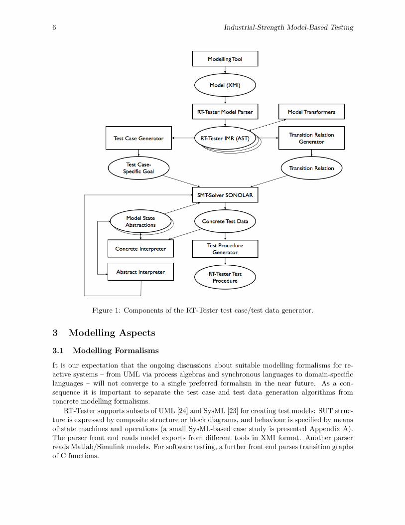
The starting point for MBT is a concrete test model describing the expected behaviour ofthe system under test (SUT) and, optionally, the behaviour of the operational environment to besimulated in test executions by the testing environment (TE) (see Fig. 1). Models developed in aspecific formalism are transformed into some textual representation supported by the modellingtool (usually XMI format). A model parser front-end reads the model text and creates aninternal model representation (IMR) of the abstract syntax.
A transition relation generator creates the initial state and the transition relation of the modelas an expression in propositional logic, referring to pre-and post-states. Model transformerscreate additional reduced, abstracted or equivalent model representations which are useful tospeed up the test case and test data generation process.
A test case generator creates propositional formulas representing test cases built accordingto a given strategy. A satisfiability modulo theory (SMT) solver calculates solutions of the testcase constraints in compliance with the transition relation. This results in concrete compu-tation fragments yielding the time stamps and input vectors to be used in the test procedureimplementing the test case (and possibly other test cases as well). An interpreter simulating themodel in compliance with the transition relation is used to investigate concrete model executionscontinuing the computation fragments calculated by the SMT solver or, alternatively, creatingnew computations based on environment simulation and random data selection. An abstractinterpreter supports the SMT solver in finding solutions faster by calculating the minimum num-ber of transition steps required to reach the goal, and by restricting the ranges of inputs andother model variables for each state possibly leading to a solution. Finally, the test proceduregenerator creates executable test procedures as required by the test execution environment bymapping the computations derived before into time-controlled commands sending input data tothe SUT and by creating test oracles from the SUT model portion checking SUT reactions onthe fly, in dependency of the stimuli received before from the TE.
6 Industrial-Strength Model-Based Testing
Figure 1: Components of the RT-Tester test case/test data generator.
3 Modelling Aspects
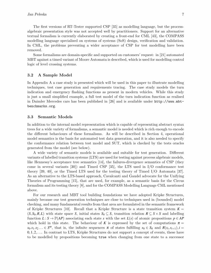
3.1 Modelling Formalisms
It is our expectation that the ongoing discussions about suitable modelling formalisms for re-active systems – from UML via process algebras and synchronous languages to domain-specificlanguages – will not converge to a single preferred formalism in the near future. As a con-sequence it is important to separate the test case and test data generation algorithms fromconcrete modelling formalisms.
RT-Tester supports subsets of UML [24] and SysML [23] for creating test models: SUT struc-ture is expressed by composite structure or block diagrams, and behaviour is specified by meansof state machines and operations (a small SysML-based case study is presented Appendix A).The parser front end reads model exports from different tools in XMI format. Another parserreads Matlab/Simulink models. For software testing, a further front end parses transition graphsof C functions.
Jan Peleska 7
The first versions of RT-Tester supported CSP [35] as modelling language, but the process-algebraic presentation style was not accepted well by practitioners. Support for an alternativetextual formalism is currently elaborated by creating a front-end for CML [43], the COMPASSmodelling language specialised on systems of systems (SoS) design, verification and validation.In CML, the problems preventing a wider acceptance of CSP for test modelling have beenremoved.
Some formalisms are domain-specific and supported on customers’ request: in [21] automatedMBT against a timed variant of Moore Automata is described, which is used for modelling controllogic of level crossing systems.
3.2 A Sample Model
In Appendix A a case study is presented which will be used in this paper to illustrate modellingtechniques, test case generation and requirements tracing. The case study models the turnindication and emergency flashing functions as present in modern vehicles. While this studyis just a small simplified example, a full test model of the turn indication function as realisedin Daimler Mercedes cars has been published in [26] and is available under http://www.mbt-
benchmarks.org.
3.3 Semantic Models
In addition to the internal model representation which is capable of representing abstract syntaxtrees for a wide variety of formalisms, a semantic model is needed which is rich enough to encodethe different behaviours of these formalisms. As will be described in Section 4, operationalmodel semantics is the basis for automated test data generation, and it is also needed to specifythe conformance relation between test model and SUT, which is checked by the tests oraclesgenerated from the model (see below).
A wide variety of semantic models is available and suitable for test generation. Differentvariants of labelled transition systems (LTS) are used for testing against process algebraic models,like Hennessy’s acceptance tree semantics [14], the failures-divergence semantics of CSP (theycome in several variants [30]) and Timed CSP [35], the LTS used in I/O conformance testtheory [39, 40], or the Timed LTS used for the testing theory of Timed I/O Automata [37].As an alternative to the LTS-based approach, Cavalcanti and Gaudel advocate for the UnifyingTheories of Programming [15], that are used, for example, as a semantic basis for the Circusformalism and its testing theory [8], and for the COMPASS Modelling Language CML mentionedabove.
For our research and MBT tool building foundations we have adopted Kripke Structures,mainly because our test generation techniques are close to techniques used in (bounded) modelchecking, and many fundamental results from that area are formulated in the semantic frameworkof Kripke Structures [10]. Recall that a Kripke Structure is a state transition system K =(S,S0,R,L) with state space S, initial states S0 ⊆ S, transition relation R ⊆ S× S and labellingfunction L : S→ P(AP) associating each state s with the set L(s) of atomic propositions p ∈ APwhich hold in this state. The behaviour of K is expressed by the set of computations π =s0.s1.s2 . . . ∈ Sω , that is, the infinite sequences π of states fulfilling s0 ∈ S0 and R(si,si+1), i =0,1,2, . . .. In contrast to LTS, Kripke Structures do not support a concept of events, these haveto be modelled by propositions becoming true when changing from one state to a successor

8 Industrial-Strength Model-Based Testing
state. For testing purposes, states s ∈ S are typically modelled by variable valuation functionss : V →D where V is a set of variable symbols x mapped by s to their current value s(x) in theirappropriate domain (bool, int, float, . . . ) which is a subset of D. The variable symbols arepartitioned into V = I ∪O∪M, where I contains the input variables of the SUT, O its outputvariables, and M its internal model variables which cannot be observed during tests. Concurrencycan be modelled both for the synchronous (“true parallelism”) [7] and the interleaving variantsof semantics [10, Chapter 10]. Discrete or dense time can be encoded by means of a variable tdenoting model execution time. For dense-time models this leads to state spaces of uncountablesize, but the abstractions of the state space according to clock regions or clock zones, as knownfrom Timed Automata [10] can be encoded by means of atomic propositions and lead to finite-state abstractions.
Observe that there should be no real controversy about whether LTS or Kripke Structuresare more suitable for describing behavioural semantics of models: De Nicola and Vaandrager [22]have shown how to construct property-preserving transformations of LTS into Kripke Structuresand vice versa.
3.4 Conformance Relations
Conformance relations specify the correctness properties of a SUT by comparing its actual be-haviour observed during test executions to the possible behaviours specified by the model. Awide variety of conformance relations are known. For Mealy automata models, Chow usedan input/output-based equivalence relation which amounted to isomorphism between minimalautomata representing specification and implementation models [9]. in the domain of processalgebras Hennessy and De Nicola introduced the relation of testing equivalence which relatedspecification process behaviour to SUT process behaviour [11]. For Lotus, this concept wasexplored in depth by Brinksma [6], Peleska and Siegel showed that it could be equally well ap-plied for CSP and its refinement relations [25], and Schneider extended these results to TimedCSP [34]. Tretmans introduced the concept of I/O conformance [39]. Vaandrager et. al. usedbi-similarity as a testing relation between timed automata representing specification and im-plementation [37]. All these conformance relations have in common, that they are defined onthe model semantics, that is, as relations between computations admissible for specification andimplementation, respectively.
Conformance in the synchronous deterministic case. For our Kripke structures, a simplevariant of I/O conformance suffices for a surprisingly wide range of applications: for every trace3
s0.s1 . . .sn identified for test purposes in the model, the associated test execution trace s′0.s′1 . . .s
′n
should have the same length and satisfy
∀i ∈ {0, . . . ,n} : si|I∪O∪{t} = s′i|I∪O∪{t}
that is, the observable input and output values, as well as the time stamps should be identical.This very simple notion of conformance is justified for the following scenarios of reactive
systems testing: (1) The SUT is non-blocking on its input interfaces, (2) the most recent valuepassed along output interfaces can always be queried in the testing environment, (3) each con-current component is deterministic, and (4) the synchronous concurrency semantics applies. At
3Traces are finite prefixes of computations.

Jan Peleska 9
first glance, these conditions may seem rather restrictive, but there is a wide variety of practicaltest applications where they apply: many SUT never refuse inputs, since they communicate viashared variables, dual-ported ram, or non-blocking state-based protocols4. Typical hardware-in-the-loop testing environments always keep the current output values of the SUT in memory forevaluation purposes, so that even message-based interfaces can be accessed as shared variablesin memory (additionally, test events may be generated when an output message of the SUTactually arrives in the test environment (TE). For safety-critical applications the control deci-sions of each sequential sub-component of the SUT must be deterministic, so that the conceptof may tests [14], where a test trace may or may not be refused by the SUT does not apply. As aconsequence, the complexity and elegance of testing theories handling non-deterministic internalchoice and associated refusal sets and unpredictable outputs of the SUT are not applicable forthese types of systems. Finally, synchronous systems are widely used for local control appli-cations, such as, for example, PLC controllers or computers adhering to the cyclic processingparadigm.
In RT-Tester this conformance relation is practically applied, for example, when testingsoftware generated from SCADE models [12]: the SCADE tool and its modelling languageadhere to the synchronous paradigm. The software operates in processing cycles. Each cyclestarts with reading input data from global variables shared with the environment; this is followedby internal processing steps, and the output variables are updated at the end of the cycle. Timet is a discrete abstraction corresponding to a counter of processing cycles.
Conformance in presence of non-determinism. For distributed control systems the syn-chronous paradigm obviously no longer applies, and though single sequential SUT componentswill usually still act in a deterministic way, their outputs will interleave non-deterministicallywith those of others executing in a concurrent way. Moreover, certain SUT outputs may changenon-deterministically over a period of time, because the exact behavioural specification is un-available. These aspects are supported in RT-Tester in the following ways.
• All SUT output interfaces y are associated with (1) an acceptable deviation εy from theaccepted value (so any observed value s′(y) deviating from the expected value s(y) by|s′(y)− s(y)| ≤ ε is acceptable), (2) an admissible latency δ 0
y (so any observed value s′(y)
for the expected value s(y) is not timed out as long as s′(t)−s(t)≤ δ 0y , and (3) an acceptable
time δ 1y for early changes of y (so s(t)− s′(t)≤ δ 1
y is still acceptable).
• A time-bounded non-deterministic assignment statement y = UNDEF(t,c) stating that y’svaluation is arbitrary for a duration of t time units, after which it should assume value c
(with an admissible deviation and an admissible delay).
• A model transformation turning the SUT model into a test oracle: it
– extends the variable space by one additional output variable y′ per SUT output y∈O,
– adds one concurrent checker component Oy per SUT output signal, operating on yand y′,
– adds one concurrent component P processing the timed input output trace as ob-served during the test execution, with observed SUT outputs written to y′ (insteadof y),
4In the avionic domain, for example, the sampling mode of the AFDX protocol [1] allows to transmit messagesin non-blocking mode, so that the receiver always reads the most recent data value.
10 Industrial-Strength Model-Based Testing
c0
c1
. . .
c0
c01
c1
[x > 0]/
y = y + x;
a = 2 ⇤ y;
[x > 0]/
y = y + x;
. . .
[z == 1]/
a = 0;
[z0 == 1]/
a = 0;
x : inputy, z: SUT model outputsy0, z0: observed SUT outputsa : internal model variable
Ci Ci
[|y0 � y| "y]/
a = 2 ⇤ y;
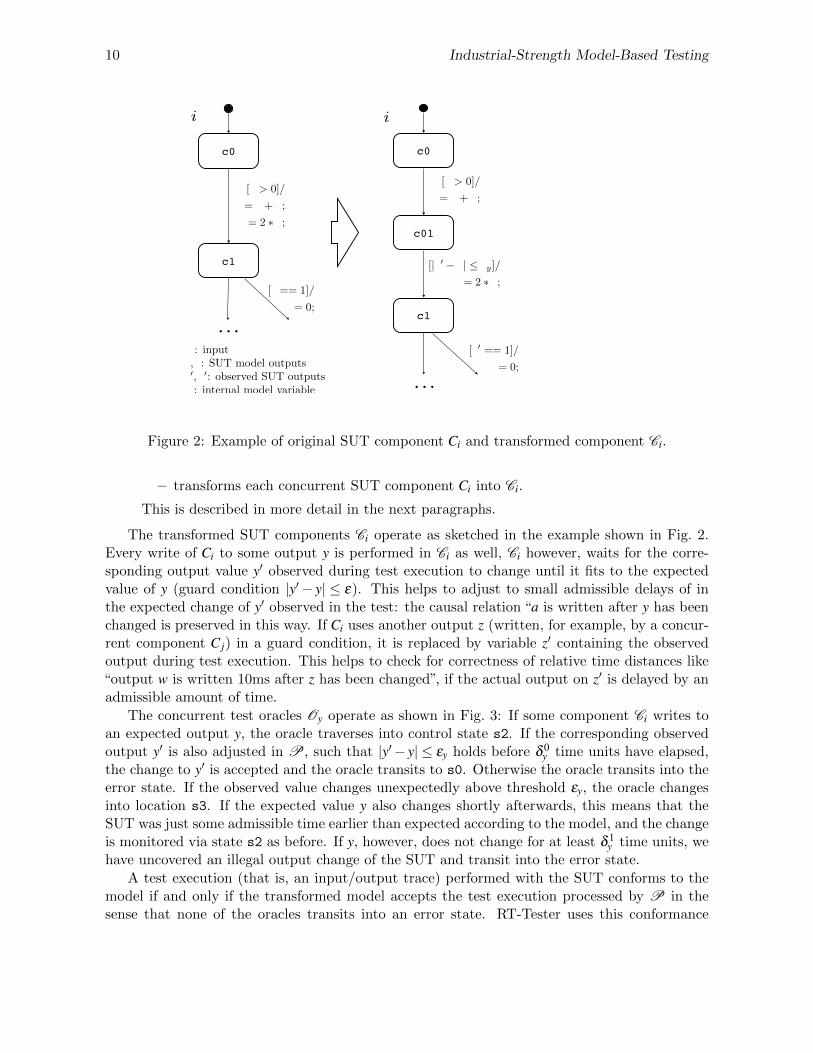
Figure 2: Example of original SUT component Ci and transformed component Ci.
– transforms each concurrent SUT component Ci into Ci.
This is described in more detail in the next paragraphs.
The transformed SUT components Ci operate as sketched in the example shown in Fig. 2.Every write of Ci to some output y is performed in Ci as well, Ci however, waits for the corre-sponding output value y′ observed during test execution to change until it fits to the expectedvalue of y (guard condition |y′− y| ≤ ε). This helps to adjust to small admissible delays of inthe expected change of y′ observed in the test: the causal relation “a is written after y has beenchanged is preserved in this way. If Ci uses another output z (written, for example, by a concur-rent component C j) in a guard condition, it is replaced by variable z′ containing the observedoutput during test execution. This helps to check for correctness of relative time distances like“output w is written 10ms after z has been changed”, if the actual output on z′ is delayed by anadmissible amount of time.
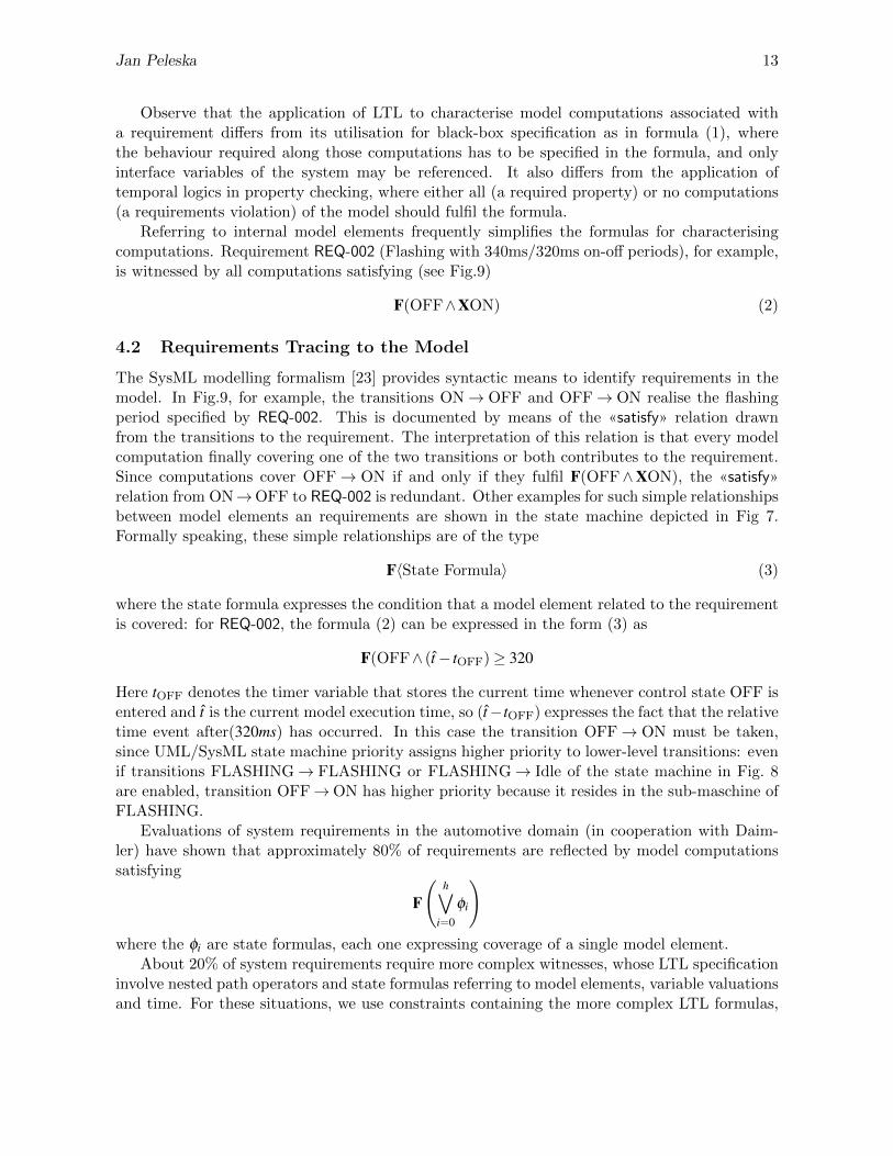
The concurrent test oracles Oy operate as shown in Fig. 3: If some component Ci writes toan expected output y, the oracle traverses into control state s2. If the corresponding observedoutput y′ is also adjusted in P, such that |y′− y| ≤ εy holds before δ 0
y time units have elapsed,the change to y′ is accepted and the oracle transits to s0. Otherwise the oracle transits into theerror state. If the observed value changes unexpectedly above threshold εy, the oracle changesinto location s3. If the expected value y also changes shortly afterwards, this means that theSUT was just some admissible time earlier than expected according to the model, and the changeis monitored via state s2 as before. If y, however, does not change for at least δ 1
y time units, wehave uncovered an illegal output change of the SUT and transit into the error state.
A test execution (that is, an input/output trace) performed with the SUT conforms to themodel if and only if the transformed model accepts the test execution processed by P in thesense that none of the oracles transits into an error state. RT-Tester uses this conformance

Jan Peleska 11
s0
s1
error
s2 s3
after(t)
[y 6= y0]/
y0 = y;
[|y � y0| > "y ^ y = y0]
[y 6= y0]/
y0 = y;
after(�1y)after(�0y)
y: expected valuey0: last expected valuey0: observed value"y: admissible deviation for y�0y: admissible latency for y�1y: admissible time for early changes of y0
�1y < �0y
UNDEF(t, c)/
y = c;[|y � y0| "y]
Figure 3: Test oracle component observing one SUT output interface y.
relation for hardware-in-the-loop system testing, as, for example, in the tests of the automotivecontroller network supporting the turn indication function in Daimler Mercedes vehicles [26].
3.5 Test-Modelling Related Challenges
With suitable test models available, test efficiency and test quality are improved in a considerableway. The elaboration of a model, however, can prove to be a major hurdle for the success ofMBT in practice.
1. If complex models have to be completed before testing can start, this induces an unac-ceptable delay for the proper test executions.
2. For complex SUT, like systems of systems, test models need to abstract from a large amountof detail, because otherwise the resulting test model would become unmanageable.
3. The required skills for test engineers writing test models are significantly higher than fortest engineers writing sequential test procedures.
We expect that problem 1 will be solved in the future by incremental model development,where test suites with increasing coverage and error detection capabilities can be run betweenmodel increments. The current methods based on sequential state machines as described by[41] may be extended to partially automated approaches where test model designers provide –apart from interface descriptions – initial architectural frames and suggestions for internal statevariables, and automated machine learning takes these information into account. Furthermore,the explicit state machine construction may be complemented by incremental elaboration oftransition relations: as pointed out by [27] for the purpose of test data generation, concurrent

12 Industrial-Strength Model-Based Testing
real-time models with complex state space are often better expressed by means of their transitionrelation than by explicit concurrent state machines. Promising attempts to construct test modelsin an incremental way from actual observations obtained during SUT simulations or experimentswith the actual SUT indicate that test model development can profit from “re-engineering” SUTproperties or model fragments from observations [29].
The problem of model complexity can be overcome by introducing contracts for the con-stituent systems of a large system of systems. This type of abstractions is investigated, forexample, in the COMPASS project5.
With respect to the third problem it is necessary to point out in management circles thatcompetent testing requires the same skills as competent software development. So if modellingskills are required for model-driven software and system development, these skills are requiredfor test engineers as well.
4 Requirements, Test Cases and Trustworthy Test Strategies
4.1 Requirements
If a test model has been elaborated in an adequate way, it will reflect the requirements to betested. At first glance, however, it may not be obvious to identify the model portions contributingto a given requirement. Formally speaking, a requirement is reflected by certain computationsπ = s0.s1.s2 . . . of the model. Computations can be identified, for example, by some variant oftemporal logic, and we use Linear Temporal Logic (LTL) [10, Chapter 3] for this purpose6.
Consider, for example, requirement REQ-001 (Flashing requires sufficient voltage) from thesample application specified in Appendix A, Table 1. It can be readily expressed in LTL as
G(Voltage≤ 80⇒ X(¬(FlashLeft∨FlashRight) U Voltage > 80)) (1)
This is a black-box specification: it only refers to input and output interfaces of the SUTand is valid without any model. With a model at hand, however, the specification can beslightly simplified, because the relevant SUT reactions have been captured by state machineOUTPUT CTRL (see Fig. 8)7.
G(Voltage≤ 80⇒ X(Idle U Voltage > 80))
In control state Idle the indication lights are never activated. Now the computations contributingto REQ-001 are exactly the ones finally fulfilling the premise Voltage ≤ 80, where the effect ofthe requirement may become visible, that is,
F(Voltage≤ 80)
It is unnecessary to specify the effects of the requirement in this formula, because we are onlyconsidering valid model computations, and the effect is encoded in the model.
5http://www.compass-research.eu6Recall that LTL uses 4 path operators: Gφ (globally φ) states that φ holds in every state of the computation.
Fφ (finally φ) states that φ holds in some computation state. Xφ states that φ holds in the next state followingthe computation state under consideration. φ U ψ states that finally ψ will hold in a computation state and φfill hold in all previous states (if any).
7Control states are encoded as Boolean variables in the model state space, Idle = true means that state machineOUTPUT CTRL is in control state Idle.
Jan Peleska 13
Observe that the application of LTL to characterise model computations associated witha requirement differs from its utilisation for black-box specification as in formula (1), wherethe behaviour required along those computations has to be specified in the formula, and onlyinterface variables of the system may be referenced. It also differs from the application oftemporal logics in property checking, where either all (a required property) or no computations(a requirements violation) of the model should fulfil the formula.
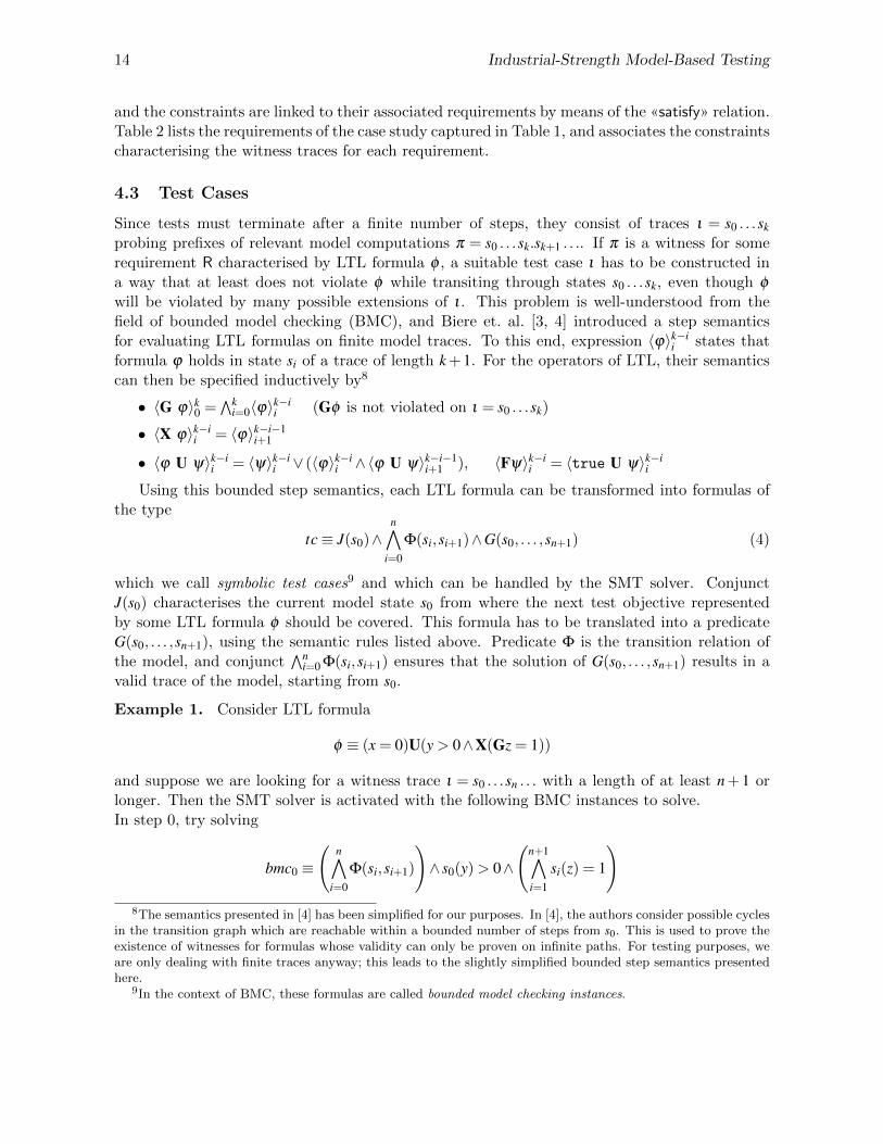
Referring to internal model elements frequently simplifies the formulas for characterisingcomputations. Requirement REQ-002 (Flashing with 340ms/320ms on-off periods), for example,is witnessed by all computations satisfying (see Fig.9)
F(OFF∧XON) (2)
4.2 Requirements Tracing to the Model
The SysML modelling formalism [23] provides syntactic means to identify requirements in themodel. In Fig.9, for example, the transitions ON→ OFF and OFF→ ON realise the flashingperiod specified by REQ-002. This is documented by means of the «satisfy» relation drawnfrom the transitions to the requirement. The interpretation of this relation is that every modelcomputation finally covering one of the two transitions or both contributes to the requirement.Since computations cover OFF→ ON if and only if they fulfil F(OFF∧XON), the «satisfy»relation from ON→OFF to REQ-002 is redundant. Other examples for such simple relationshipsbetween model elements an requirements are shown in the state machine depicted in Fig 7.Formally speaking, these simple relationships are of the type
F〈State Formula〉 (3)
where the state formula expresses the condition that a model element related to the requirementis covered: for REQ-002, the formula (2) can be expressed in the form (3) as
F(OFF∧ (t− tOFF)≥ 320
Here tOFF denotes the timer variable that stores the current time whenever control state OFF isentered and t is the current model execution time, so (t−tOFF) expresses the fact that the relativetime event after(320ms) has occurred. In this case the transition OFF→ ON must be taken,since UML/SysML state machine priority assigns higher priority to lower-level transitions: evenif transitions FLASHING→ FLASHING or FLASHING→ Idle of the state machine in Fig. 8are enabled, transition OFF→ON has higher priority because it resides in the sub-maschine ofFLASHING.
Evaluations of system requirements in the automotive domain (in cooperation with Daim-ler) have shown that approximately 80% of requirements are reflected by model computationssatisfying
F
(h∨
i=0
φi
)
where the φi are state formulas, each one expressing coverage of a single model element.About 20% of system requirements require more complex witnesses, whose LTL specification
involve nested path operators and state formulas referring to model elements, variable valuationsand time. For these situations, we use constraints containing the more complex LTL formulas,
14 Industrial-Strength Model-Based Testing
and the constraints are linked to their associated requirements by means of the «satisfy» relation.Table 2 lists the requirements of the case study captured in Table 1, and associates the constraintscharacterising the witness traces for each requirement.
4.3 Test Cases
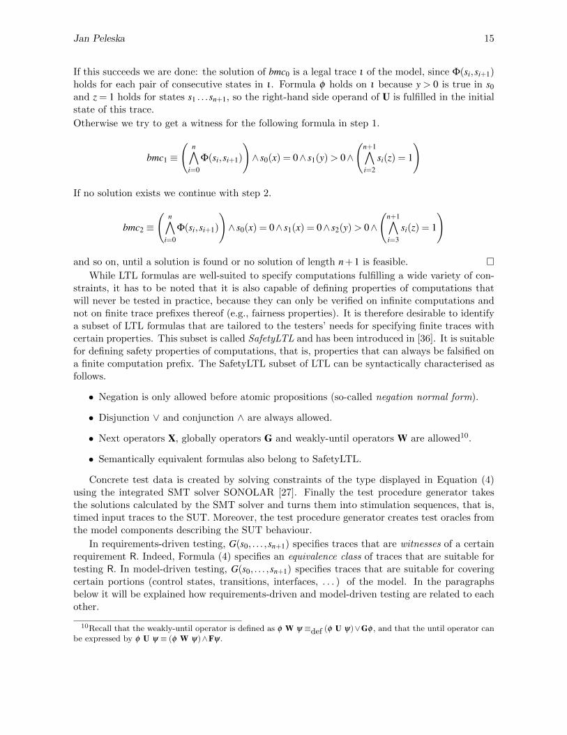
Since tests must terminate after a finite number of steps, they consist of traces ι = s0 . . .skprobing prefixes of relevant model computations π = s0 . . .sk.sk+1 . . .. If π is a witness for somerequirement R characterised by LTL formula φ , a suitable test case ι has to be constructed ina way that at least does not violate φ while transiting through states s0 . . .sk, even though φwill be violated by many possible extensions of ι . This problem is well-understood from thefield of bounded model checking (BMC), and Biere et. al. [3, 4] introduced a step semanticsfor evaluating LTL formulas on finite model traces. To this end, expression 〈ϕ〉k−i
i states thatformula ϕ holds in state si of a trace of length k + 1. For the operators of LTL, their semanticscan then be specified inductively by8
• 〈G ϕ〉k0 =∧k
i=0〈ϕ〉k−ii (Gφ is not violated on ι = s0 . . .sk)
• 〈X ϕ〉k−ii = 〈ϕ〉k−i−1
i+1
• 〈ϕ U ψ〉k−ii = 〈ψ〉k−i
i ∨ (〈ϕ〉k−ii ∧〈ϕ U ψ〉k−i−1
i+1 ), 〈Fψ〉k−ii = 〈true U ψ〉k−i
i
Using this bounded step semantics, each LTL formula can be transformed into formulas ofthe type
tc≡ J(s0)∧n∧
i=0
Φ(si,si+1)∧G(s0, . . . ,sn+1) (4)
which we call symbolic test cases9 and which can be handled by the SMT solver. ConjunctJ(s0) characterises the current model state s0 from where the next test objective representedby some LTL formula φ should be covered. This formula has to be translated into a predicateG(s0, . . . ,sn+1), using the semantic rules listed above. Predicate Φ is the transition relation ofthe model, and conjunct
∧ni=0 Φ(si,si+1) ensures that the solution of G(s0, . . . ,sn+1) results in a
valid trace of the model, starting from s0.
Example 1. Consider LTL formula
φ ≡ (x = 0)U(y > 0∧X(Gz = 1))
and suppose we are looking for a witness trace ι = s0 . . .sn . . . with a length of at least n + 1 orlonger. Then the SMT solver is activated with the following BMC instances to solve.In step 0, try solving
bmc0 ≡(
n∧
i=0
Φ(si,si+1)
)∧ s0(y) > 0∧
(n+1∧
i=1
si(z) = 1
)
8The semantics presented in [4] has been simplified for our purposes. In [4], the authors consider possible cyclesin the transition graph which are reachable within a bounded number of steps from s0. This is used to prove theexistence of witnesses for formulas whose validity can only be proven on infinite paths. For testing purposes, weare only dealing with finite traces anyway; this leads to the slightly simplified bounded step semantics presentedhere.
9In the context of BMC, these formulas are called bounded model checking instances.
Jan Peleska 15
If this succeeds we are done: the solution of bmc0 is a legal trace ι of the model, since Φ(si,si+1)holds for each pair of consecutive states in ι . Formula φ holds on ι because y > 0 is true in s0and z = 1 holds for states s1 . . .sn+1, so the right-hand side operand of U is fulfilled in the initialstate of this trace.
Otherwise we try to get a witness for the following formula in step 1.
bmc1 ≡(
n∧
i=0
Φ(si,si+1)
)∧ s0(x) = 0∧ s1(y) > 0∧
(n+1∧
i=2
si(z) = 1
)
If no solution exists we continue with step 2.
bmc2 ≡(
n∧
i=0
Φ(si,si+1)
)∧ s0(x) = 0∧ s1(x) = 0∧ s2(y) > 0∧
(n+1∧
i=3
si(z) = 1
)
and so on, until a solution is found or no solution of length n + 1 is feasible. �While LTL formulas are well-suited to specify computations fulfilling a wide variety of con-
straints, it has to be noted that it is also capable of defining properties of computations thatwill never be tested in practice, because they can only be verified on infinite computations andnot on finite trace prefixes thereof (e.g., fairness properties). It is therefore desirable to identifya subset of LTL formulas that are tailored to the testers’ needs for specifying finite traces withcertain properties. This subset is called SafetyLTL and has been introduced in [36]. It is suitablefor defining safety properties of computations, that is, properties that can always be falsified ona finite computation prefix. The SafetyLTL subset of LTL can be syntactically characterised asfollows.
• Negation is only allowed before atomic propositions (so-called negation normal form).
• Disjunction ∨ and conjunction ∧ are always allowed.
• Next operators X, globally operators G and weakly-until operators W are allowed10.
• Semantically equivalent formulas also belong to SafetyLTL.
Concrete test data is created by solving constraints of the type displayed in Equation (4)using the integrated SMT solver SONOLAR [27]. Finally the test procedure generator takesthe solutions calculated by the SMT solver and turns them into stimulation sequences, that is,timed input traces to the SUT. Moreover, the test procedure generator creates test oracles fromthe model components describing the SUT behaviour.
In requirements-driven testing, G(s0, . . . ,sn+1) specifies traces that are witnesses of a certainrequirement R. Indeed, Formula (4) specifies an equivalence class of traces that are suitable fortesting R. In model-driven testing, G(s0, . . . ,sn+1) specifies traces that are suitable for coveringcertain portions (control states, transitions, interfaces, . . . ) of the model. In the paragraphsbelow it will be explained how requirements-driven and model-driven testing are related to eachother.
10Recall that the weakly-until operator is defined as φ W ψ ≡def (φ U ψ)∨Gφ , and that the until operator canbe expressed by φ U ψ ≡ (φ W ψ)∧Fψ.
16 Industrial-Strength Model-Based Testing
4.4 Model Coverage Test Cases
Since adequate test models express all SUT requirements to be tested, it is reasonable to specifyand perform test cases achieving model coverage. As we have seen above, a behavioural modelelement (state machine control state, transition, operation, . . . ) is covered by a trace ι = s0 . . .sk,if the element’s behaviour is exercised during some transition si → si+1. For a control state cthis means that si+1(c) = true, and, consequently, the state’s entry action (if any) is executed.For a transition this means that its firing condition becomes true in some si. Operations f arecovered when they are associated with actions of covered states or transitions executing f .
There exists a wide variety of model coverage strategies, many of them are discussed in [42].The standards for safety-critical systems development and V&V have only recently started toconsider the model-driven development and V&V paradigm. It seems that the avionic stan-dard RTCA DO-178C [32] is currently the most advanced with respect to model-based systemsengineering. It requires to achieve operation coverage, transition coverage, decision coverage,and equivalence class and boundary value coverage, when verifying design models [31, TableMB.6-1]. Neither the standard, nor [42], however, elaborate on coverage of timing conditions(e.g., clock zones in Time Automata) or the coverage of execution state vectors of concurrentmodel components.
In RT-Tester, the following model coverage criteria are currently implemented: (1) basiccontrol state coverage, (2) transition coverage, MC/DC coverage, (3) hierarchic transition cov-erage11 with or without MC/DC coverage, (4) equivalence class and boundary value coverage,(5) basic control state pairs coverage, (6) interface coverage and (7) block coverage.
Basic control state pairs coverage exercises all feasible control state combinations of concur-rent state machines in writer-reader relationship. The equivalence class coverage technique incombination with basic control state pairs coverage also produces a (not necessarily complete)coverage of clock zones.
Each of these coverage criteria can be specified by means of LTL formulas or, equivalently,BMC instances.
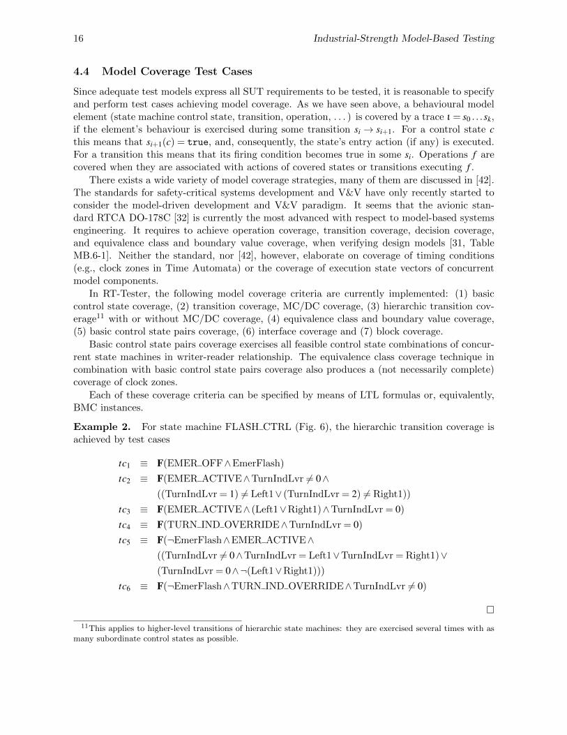
Example 2. For state machine FLASH CTRL (Fig. 6), the hierarchic transition coverage isachieved by test cases
tc1 ≡ F(EMER OFF∧EmerFlash)
tc2 ≡ F(EMER ACTIVE∧TurnIndLvr 6= 0∧((TurnIndLvr = 1) 6= Left1∨ (TurnIndLvr = 2) 6= Right1))
tc3 ≡ F(EMER ACTIVE∧ (Left1∨Right1)∧TurnIndLvr = 0)
tc4 ≡ F(TURN IND OVERRIDE∧TurnIndLvr = 0)
tc5 ≡ F(¬EmerFlash∧EMER ACTIVE∧((TurnIndLvr 6= 0∧TurnIndLvr = Left1∨TurnIndLvr = Right1)∨(TurnIndLvr = 0∧¬(Left1∨Right1)))
tc6 ≡ F(¬EmerFlash∧TURN IND OVERRIDE∧TurnIndLvr 6= 0)
�11This applies to higher-level transitions of hierarchic state machines: they are exercised several times with as
many subordinate control states as possible.

Jan Peleska 17
4.5 Automated Compilation of Traceability Data
Having identified the test cases suitable for model coverage, these can be related to requirementsin an automated way.
• If requirement R is linked to model elements by «satisfy» relationships, then the test casescovering these elements are automatically related to R.
• If requirement R is characterised by a LTL formula φ not directly related to model elements,we proceed as follows.
– Transform φ into disjunctive normal form φ ≡∨mi=0 φi and associate test cases for each
φi separately.
– Each test case tc≡ ψ derived from the model is related to R, if ψ ⇒ φi holds.
– If test case tc ≡ ψ is neither stronger nor weaker than the requirement in the sensethat ψ ∧φi has a solution, add a new test case tc′ ≡ ψ ∧φi and relate tc′ to R.
– If at least one of two test cases tc1 ≡ Fψ1 and tc2 ≡ Fψ2 implies the requirement andtc′ ≡ F(ψ1∧ψ2) has a solution, add tc′ to the test case database and trace it to R.
Example 3. Consider requirement REQ-002 (Flashing with 340ms/320ms on-off periods) ofthe example from Table 1. It is characterised by covering transitions ON→OFF and OFF→ON(see Table 2). By tracing these transitions back to model coverage test cases, the following casescan be identified, and these trace back to REQ-002.
tc7 ≡ F(OFF∧ (t− tOFF)≥ 320)
tc8 ≡ F(OFF∧ (t− tOFF)≥ 320∧TurnIndLvr = 1)
tc9 ≡ F(OFF∧ (t− tOFF)≥ 320∧TurnIndLvr = 2)
tc10 ≡ F(OFF∧ (t− tOFF)≥ 320∧EMER ACTIVE)
tc11 ≡ F(OFF∧ (t− tOFF)≥ 320∧TURN IND OVERRIDE)
�The test cases listed here are only a subset of the complete list that traces back to REQ-
002. Test cases tc8, tc9 result from combining interface coverage on SUT input TurnIndLvrwith coverage of the OFF→ON. Cases tc10, tc11 result from combining basic control state pairscoverage with the transition coverage. Test case tc7 is redundant if any of the others is performed.It is quite obvious that the test case generation technique defined above runs into combinatorialexplosion problems. Even for the small sample system discussed here, the list of test cases fromExample 3 could be extended by
tc12 ≡ F(OFF∧ (t− tOFF)≥ 320∧EMER ACTIVE∧TurnIndLvr = 0)
tc13 ≡ F(OFF∧ (t− tOFF)≥ 320∧EMER ACTIVE∧TurnIndLvr = 1)
tc14 ≡ F(OFF∧ (t− tOFF)≥ 320∧EMER ACTIVE∧TurnIndLvr = 2)
. . .
4.6 Test Case Selection According to Criticality
It is quite obvious that the number of test cases related to a requirement can become quite vast,and that some of the test cases investigate more specific situations than others. This problem
18 Industrial-Strength Model-Based Testing
is closely related to the problem of exhaustive testing which will be discussed below. Since anexhaustive execution of all test case combinations related to a requirement will be impossiblefor fair-sized systems, a justified reduction of the potentially applicable test cases to a smallercollection is required. In the case of safety-critical systems development, such a justificationshould conform to the standards applicable for V&V of these systems.
In the case of avionic systems, the RTCA DO-178C standard [32] requires structural testswith respect to data and control coupling and full requirements coverage through testing, butdoes not specify when a requirement has been verified with a sufficient number of test cases.Instead, the standard gives test end criteria by setting code coverage goals, the coverage to beachieved depending on the SUT’s criticality [31, MB.C-7]: for assurance level 1 systems (highestcriticality), MC/DC coverage has to be achieved, for level 2 decision coverage, and for level 3statement coverage. For levels 4 and 5, only high-level requirements have to be covered withoutsetting any code coverage goals, and for assurance level 5 the requirement to test data andcontrol coupling is dropped.
As a consequence, the model-based test case coverage can be tuned according to the codecoverage achieved, whenever the source code is available and the assurance level is in 1 — 3:start with basic control state coverage cases related to the requirement, increase coverage byadding hierarchic and MC/DC coverage test cases until the required code coverage is achieved.Add interface and basic control state pairs coverage cases until the data and control couplingcoverage has been achieved as well. For levels 4 or 5, no discussion is necessary, since here any“reasonable” test case assignment to each high-level requirement is acceptable, due to the lowcriticality of the SUT.
When MBT is applied on system level, however, it will generally be infeasible to measurecode coverage achieved during system tests. For systems of systems, in particular, system-leveltests will never cover any significant amount of code coverage, and the coverage values achievedwill not be obtainable in most cases, both for technical and for security reasons. Here we suggestto proceed as follows.
• For assurance level 3, exercise
– interface tests – this ensures verification of data and control coupling,
– basic control state coverage test cases,
– refine these test cases tc ≡ ψ only if requirements have stricter characterisations φi;in this case add tc′ ≡ ψ ∧φi.
• For assurance level 2, follow the same pattern, but use transition coverage test cases.
• For assurance level 1, exercise
– interface tests,
– basic control state pairs coverage test cases to refine the data and control couplingtests (recall that these test cases stem from writer-reader analyses),
– MC/DC coverage test cases in combination with hierarchic transition coverage,
– first-level refinements of test cases related to requirements as illustrated in Example 3,
– second level refinements (as in test cases tc12, tc13, tc14 above), if the additional con-juncts have direct impact on the requirement.
Following these rules, and supposing that our sample system were of assurance level 1, the testcases displayed in Example 3 would be necessary. Test cases tc12, tc13, tc14, however, would not

Jan Peleska 19
be required, since the TurnIndLvr has no impact on REQ-002 according to the model: the risk ofa hidden impact of this interface on the requirement has already been taken into account whentesting tc8, tc9.
4.6.1 Test Strategies Proving Conformance
An alternative for justifying test strategies consists in proving that they will finally convergeto an exhaustive test suite establishing some conformance relation between model and SUT.This approach has a long tradition: one of the first contributions in this field was Chow’s W-Method [9] applicable for minimal state machines, which was generalised and extended intomany directions, so that even in the core of the exhaustive test strategy for timed automata [37]some argument from the W-Method is used.
Though execution of exhaustive test suites will generally be infeasible in practice, convergenceto exhaustive test suites ensures that new test cases added to the suite will really increase theassurance level by a positive amount: intuitively designed test strategies often do not possessthis property, because additional test cases may just re-test SUT aspects already covered byexisting ones.
The known exhaustive strategies typically operate on finite data types (discrete events, orvariables with data ranges that can easily be enumerated). It is an interesting research challengewhether similar results can be obtained in presence of large data types, if application of equiv-alence class partitioning is justified. In [13] the authors formalise the concept of equivalenceclass partitioning and prove that exhaustive suites can be constructed for white-box test situa-tions. In [18] this approach is currently generalised within the COMPASS project with respectto black-box testing and semantic models that are more general than the one underlying theresults presented in [13].
4.7 Challenges to Test Case Generation and Test Strategy Design
The size of SoS state spaces implies that exhaustive investigation of the complete concrete statespace will certainly be infeasible. We suggest to tackle this problem by two orthogonal strategies,as is currently investigated in the COMPASS project [17].
• On constituent system level, different behaviours associated with the same local missionthreads12 will be comprised in equivalence classes. This reduces the complexity problemfor SoS system testing to covering combinations of classes of constituent system behavioursinstead of sequences of concrete state vector combinations.
• On SoS system level, “relevant” class combinations are identified by means of differentvariants of impact analysis, such as data flow analyses or investigation of contractualdependencies. Behaviours of constituent systems which do not affect the relevant classcombinations under consideration will be selected according to the principle of orthogo-nal arrays [28], because this promises an effective combinatorial distribution of unrelatedbehaviours exercised concurrently with the critical ones.
Apart from size and complexity, SoS present another challenge, because they typically changetheir configuration dynamically during run-time. The dynamic adaptation of test objectives is
12Mission threads are end-to-end tests; in the context described here, mission threads are executed on constituentsystem level.
20 Industrial-Strength Model-Based Testing
particularly relevant for run-time acceptance testing of changing SoS configurations. In contrastto development models for SoS, however, we only have to consider bounded changes of SoSconfigurations, because every test suite can only consider a bounded number of configurationsanyway. It remains to investigate how to determine configurations possessing sufficient errordetection strength. Results from the field of mutation testing will help to determine this strengthin a systematic and measurable way.
A further problem for systems of SoS complexity is presented by the fact that not everybehaviour can be full captured in the model, which results in under-specification and non-determinism. Test strategy elaboration in presence of this problem be achieved in the followingway.
• The SoS system behaviour is structured into several top-level operational modes. It isexpected that switching between these modes can be performed in a deterministic way fornormal behaviour tests: it is unlikely that SoS performing operational mode changes onlyon a random basis are acceptable and “testworthy”.
• Entry into failure modes is non-deterministic, but can be initiated in a deterministic wayfor test purposes by means of pre-planned failure injections.
• The behaviour in each operational mode is not completely deterministic, but can be cap-tured by sets of constraints governing the acceptable computations in each mode. Testoracles will therefore no longer check for explicit output traces of the SUT but for compli-ance of the traces observed with the constraints applicable in each mode.
• For test stimulation purposes the SMT solver computes sequences of feasible mode switchesand the test data provoking these switches.
• Incremental test model elaboration can be performed by adding constraints identified dur-ing test observations to the modes where they are applicable. To this end, techniques frommachine learning seem to be promising.
Justification of test strategies will be performed by proving that they will “converge” toexhaustive tests proving some compliance relation between SUT and reference model.
5 Conclusion
In this article several aspects of industrial-strength model-based testing and its underlying meth-ods have been presented. A reference tool has been described, so that the presentation may serveas a benchmark for alternative tools capable of handling test campaigns of equal or even highercomplexity. Readers are invited to join the discussion on suitable benchmarks for MBT tools –initial suggestions on benchmarking can be found in [26] – and to contribute case studies andmodels to the MBT benchmark website http://www.mbt-benchmarks.org.
A further topic beyond the scope of this paper is of considerable importance for tool builders:MBT tools automating test campaigns for safety-relevant systems have to be qualified, and stan-dards like RTCA DO-178C [32] for the avionic domain, CENELEC EN650128 [38] for the railwaydomain, and ISO 26262 [19] for the automotive domain have rather precise policies about howtool qualification can be obtained. A detailed comparison between tool qualification require-ments of these standards is presented in [16], and it is described in [5] how tool qualification hasbeen obtained for RT-Tester. We believe that the complexity of the algorithms required in MBT

Jan Peleska 21
tools justifies that effort is spent on their qualification, so that their automated application willnot mask errors of the SUT due to undetected failures in the tool.
Acknowledgements. The author would like to thank the organisers of the MBT 2013 forgiving him the opportunity to present the ideas summarised in this paper. Special thanks goto Jorg Brauer, Elena Gorbachuk, Wen-ling Huang, Florian Lapschies and Uwe Schulze forcontributing to the results presented here.
References
[1] AERONAUTICAL RADIO, INC. (2009): Aircraft Data Network, Part 7, Avionics Full-DuplexSwitched Ethernet Network. AERONAUTICAL RADIO, INC., 2551 Riva Road, Annapolis, Mary-land 21401-7435.
[2] Paul Baker, Oystein Haugen, Zhen Ru Dai, Clay Williams & Jens Grabowski (2008): Model-DrivenTesting – Using the UML Testing Profile. Springer, Berlin Heidelberg.
[3] Armin Biere, Alessandro Cimatti, Edmund M. Clarke & Yunshan Zhu (1999): Symbolic Model Check-ing without BDDs. In: Proceedings of the 5th International Conference on Tools and Algorithms forConstruction and Analysis of Systems, TACAS ’99, Springer-Verlag, London, UK, UK, pp. 193–207,doi:10.1007/3-540-49059-0 14.
[4] Armin Biere, Keijo Heljanko, Tommi Junttila, Timo Latvala & Viktor Schuppan (2006): LinearEncodings of Bounded LTL Model Checking. Logical Methods in Computer Science 2(5), pp. 1–64,doi:10.2168/LMCS-2(5:5)2006.
[5] Jorg Brauer, Jan Peleska & Uwe Schulze (2012): Efficient and Trustworthy Tool Qualification forModel-Based Testing Tools. In Brian Nielsen & Carsten Weise, editors: Testing Software and Systems.Proceedings of the 24th IFIP WG 6.1 International Conference, ICTSS 2012, Aalborg, Denmark,November 2012, Lecture Notes in Computer Science 7641, Springer, Heidelberg Dordrecht LondonNew York, pp. 8–23, doi:10.1007/978-3-642-34691-0 3.
[6] E. Brinksma (1988): A Theory for the Derivation of Tests. In S. Aggarwal & K. Sabnani, editors:Protocol Specification Testing and Verification VIII (PSTV ‘88), pp. 63–74.
[7] R. E. Bryant, P. Chauhan, E. M. Clarke & A. Goel (2000): A Theory of Consistency for ModularSynchronous Systems. In W. A. Hunt & S. D. Johnson, editors: Formal Methods in Computer-AidedDesign (FMCAD), Lecture Notes in Computer Science 1954, Springer, pp. 486–504, doi:10.1007/3-540-40922-X 30.
[8] A. L. C. Calvalcanti & M.-C. Gaudel (2011): Testing for Refinement in Circus. Acta Informatica48(2), pp. 97–147, doi:10.1007/s00236-011-0133-z.
[9] Tsun S. Chow (1978): Testing Software Design Modeled by Finite-State Machines. IEEE Transactionson Software Engineering SE-4(3), pp. 178–186, doi:10.1109/TSE.1978.231496.
[10] Edmund M. Clarke, Orna Grumberg & Doron A. Peled (1999): Model Checking. The MIT Press,Cambridge, Massachusetts.
[11] R. De Nicola & M. Hennessy (1984): Testing Equivalences for Processes. Theoretical ComputerScience 34, pp. 83–133, doi:10.1016/0304-3975(84)90113-0.
[12] Esterel Technologies: SCADE Suite Product Description. http://www.estereltechnologies.com.
[13] Wolfgang Grieskamp, Yuri Gurevich, Wolfram Schulte & Margus Veanes (2002): Generating FiniteState Machines from Abstract State Machines. ACM SIGSOFT Software Engineering Notes 27(4),pp. 112–122, doi:10.1145/566171.566190.
[14] M. Hennessy (1988): Algebraic Theory of Processes. MIT Press, Cambridge, Massachusetts, London.
22 Industrial-Strength Model-Based Testing
[15] C. A. R. Hoare & H. Jifeng (1998): Unifying Theories of Programming. Prentice-Hall.
[16] Wen ling Huang, Jan Peleska & Uwe Schulze (2013): Test Automation Support. Technical ReportD34.1, COMPASS Comprehensive Modelling for Advanced Systems of Systems.
[17] Wen ling Huang, Jan Peleska & Uwe Schulze (to appear 2014): Specialised Test Strategies. TechnicalReport D34.2, COMPASS Comprehensive Modelling for Advanced Systems of Systems.
[18] Wen-ling Huang & Jan Peleska (2012): Specialised Test Strategies. Public Document, COMPASSComprehensive Modelling for Advanced Systems of Systems.
[19] (2009): Road Vehicles - Functional Safety - Part 8: Supporting Processes. Technical Report, Inter-national Organization for Standardization. ICS 43.040.10.
[20] ISO/DIS 26262-4 (2009): Road vehicles – functional safety – Part 4: Product development: systemlevel. Technical Report, International Organization for Standardization.
[21] Helge Loding & Jan Peleska (2010): Timed Moore Automata: Test Data Generation and ModelChecking. Software Testing, Verification, and Validation, 2008 International Conference on 0, pp.449–458, doi:10.1109/ICST.2010.60.
[22] Rocco De Nicola & Frits Vaandrager (1990): Action versus State based Logics for Transition Systems.In Irene Guessarian, editor: Semantics of Systems of Concurrent Processe, LNCS 469, Springer-Verlag, Berlin, Heidelberg, pp. 407–419, doi:10.1007/3-540-53479-2 17.
[23] Object Management Group (2010): OMG Systems Modeling Language (OMG SysMLT M). TechnicalReport, Object Management Group. OMG Document Number: formal/2010-06-02.
[24] OMG (2011): OMG Unified Modeling Language (OMG UML) Superstructure ver. 2.4.1.www.uml.org/spec/UML/2.4.1/Superstructure/PDF/.
[25] J. Peleska & M. Siegel (1997): Test Automation of Safety-Critical Reactive Systems. South AfricanComputer Jounal 19, pp. 53–77.
[26] Jan Peleska, Artur Honisch, Florian Lapschies, Helge Loding, Hermann Schmid, Peer Smuda, ElenaVorobev & Cornelia Zahlten (2011): A Real-World Benchmark Model for Testing Concurrent Real-Time Systems in the Automotive Domain. In Burkhart Wolff & Fatiha Zaidi, editors: TestingSoftware and Systems. Proceedings of the 23rd IFIP WG 6.1 International Conference, ICTSS2011, LNCS 7019, IFIP WG 6.1, Springer, Heidelberg Dordrecht London New York, pp. 146–161,doi:10.1007/978-3-642-24580-0 1.
[27] Jan Peleska, Elena Vorobev & Florian Lapschies (2011): Automated Test Case Generation withSMT-Solving and Abstract Interpretation. In Mihaela Bobaru, Klaus Havelund, Gerard J. Holzmann& Rajeev Joshi, editors: Nasa Formal Methods, Third International Symposium, NFM 2011, LNCS6617, Springer, Pasadena, CA, USA, pp. 298–312, doi:10.1007/978-3-642-20398-5 22.
[28] M. S. Phadke (1989): Quality Engineering Using Robust Design. Prentice Hall, Englewood Cliff, NJ.
[29] F. Rogin, T. Klotz, G. Fey, R. Drechsler & S. Rulke (2009): Advanced Verification by AutomaticProperty Generation. IET Computers & Digital Techniques 3(4), pp. 338–353, doi:10.1049/iet-cdt.2008.0110. Available at http://link.aip.org/link/?CDT/3/338/1.
[30] A. W. Roscoe (2010): Understanding Concurrent Systems. Springer.
[31] RTCA SC-205/EUROCAE WG-71 (2011): Model-Based Development and Verification Supplementto DO-178C and DO-278A. RTCA/DO-331, RTCA, Inc., 1140 Connecticut Avenue, N.W., Suite1020, Washington, D.C. 20036.
[32] RTCA SC-205/EUROCAE WG-71 (2011): Software Considerations in Airborne Systems and Equip-ment Certification. RTCA/DO-178C, RTCA, Inc., 1140 Connecticut Avenue, N.W., Suite 1020,Washington, D.C. 20036.
[33] RTCA,SC-167 (1992): Software Considerations in Airborne Systems and Equipment Certification,RTCA/DO-178B. RTCA.

Jan Peleska 23
[34] S. Schneider (1995): An Operational Semantics for Timed CSP. Information and Computation 116,pp. 193–213, doi:10.1006/inco.1995.1014.
[35] S. Schneider (2000): Concurrent and Real-time Systems – The CSP Approach. Wiley and Sons Ltd.
[36] A. P. Sistla (1994): Liveness and Fairness in Temporal Logic. Formal Aspects of Computing 6(5),pp. 495–512, doi:10.1007/BF01211865.
[37] J.G. Springintveld, F.W. Vaandrager & P.R. D’Argenio (2001): Testing timed automata. TheoreticalComputer Science 254(1-2), pp. 225–257, doi:10.1016/S0304-3975(99)00134-6.
[38] European Committee for Electrotechnical Standardization (2001): EN 50128 – Railway applications– Communications, signalling and processing systems – Software for railway control and protectionsystems. CENELEC, Brussels.
[39] Jan Tretmans (1996): Test generation with inputs, outputs and repetitive quiescence. Software –Concepts and Tools 17(3), pp. 103–120.
[40] Jan Tretmans (1999): Testing Concurrent Systems: A Formal Approach. In J.C.M. Naeten &S. Mauw, editors: CONCUR’99 – 10th Int. Conference on Concurrency Theory, Lecture Notes inComputer Science 1664, Springer, pp. 46–65, doi:10.1007/3-540-48320-9 6.
[41] Frits Vaandrager (2012): Active Learning of Extended Finite State Machines. In Brian Nielsen &Carsten Weise, editors: Testing Software and Systems. Proceedings of the 24th IFIP WG 6.1 Inter-national Conference, ICTSS 2012, Aalborg, Denmark, November 2012, Lecture Notes in ComputerScience 7641, Springer, Heidelberg Dordrecht London New York, pp. 5–7, doi:10.1007/978-3-642-34691-0 2.
[42] Stephan Weißleder (2010): Test Models and Coverage Criteria for Automatic Model-Based TestGeneration with UML State Machines. Doctoral thesis, Humboldt-University Berlin, Germany.
[43] J. Woodcock, A. Cavalcanti, J. Fitzgerald, P. Larsen, A. Miyazawa & S. Perry (2012): Fea-tures of CML: a Formal Modelling Language for Systems of Systems. IEEE Systems Journal 6,doi:10.1109/SYSoSE.2012.6384144.
A Case Study: Turn Indication Control Function
As a case study we consider the turn indication function of a vehicle providing left/right in-dication and emergency flashing by means of exterior lights flashing with a given frequency.Left/right indication is switched on by means of the turn indicator lever with its positions 0(neutral), 1 (left), and 2(right). Emergency flashing is controlled by means of a switch withpositions 0 (off) and 1 (on). Activating the indication lights is subject to the condition that theavailable voltage is sufficiently high. The requirements for the turn indication function are asshown in Table 1.
The SysML test model for this system structured into TE and SUT blocks, as shown inFig. 4. The interfaces shown in this diagram are the observable SUT outputs and writableinputs that may be accessed by the TE. RT-Tester allows for SysML properties and signalevents to be exchanged between SUT and TE model components. The tool provides interfacemodules mapping their valuations onto concrete software or hardware interfaces and vice versa.In a software integration test the turn indication lever values and the status of the emergencyswitch may be passed to the SUT, for example, by means of shared variables. The SUT outputs(left-hand side lamps on/off, right-hand side lamps on/off) can also be represented by Booleanoutput variables of the SUT. In a HW/SW integration test interface modules would map theturn indication lever status and the emergency flash button to discrete inputs to the SUT. In asystem integration test the actual voltage and the current placed by the SUT on the indication

24 Industrial-Strength Model-Based Testing
Table 1: Requirements of the turn indication control system
Requirement Description
REQ-001 Flashing requires sufficientvoltage
Indication lights are only active, if the electrical voltage (input Voltage)is > 80% of the nominal voltage.
REQ-002 Flashing with340ms/320ms on-off periods
If any lights are flashing, this is done synchronously with a 340ms ON –320ms OFF period.
REQ-003 Switch on turn indicationleft
An input change from turn indication lever state TurnIndLvr = 0 or 2to TurnIndLvr = 1 switches indication lights left (output FlashLeft) intoflashing mode and switches indication lights right (output FlashRight)off.
REQ-004 Switch on turn indicationright
An input change from turn indication lever state TurnIndLvr = 0 or 1to TurnIndLvr = 2 switches indication lights right (output FlashRight)into flashing mode and switches indication lights left (output FlashLeft)off.
REQ-005 Emergency flashing onoverrides left/right flashing
An input change from EmerFlash = 0 to EmerFlash = 1 switches indi-cation lights left (output FlashLeft) and right (output FlashRight) intoflashing mode, regardless of any previously activated turn indication.
REQ-006 Left-/right flashing over-rides emergency flashing
Activation of the turn indication left or right overrides emergency flash-ing, if the latter has been activated before.
REQ-007 Resume emergency flash-ing
If turn indication left or right is switched off and emergency flashing isstill active, emergency flashing is continued or resumed, respectively.
REQ-008 Resume turn indicationflashing
If emergency flashing is turned off and turn indication left or right is stillactive, the turn indication is continued or resumed, respectively.
REQ-009 Tip flashing If turn indication left or right is switched off before three flashing periodshave elapsed, the turn indication will continue until three on-off periodshave been performed.

Jan Peleska 25
Figure 4: Interface between TE and SUT.
lamps would be measured. The interface abstraction required for the test level is specified by asignal map that associates abstract SysML model interfaces with concrete interfaces of the testequipment.
The structural view on the SUT has to be decomposed further, until each block is associatedwith a sequential behaviour. For the case study discussed here, the SUT is further decomposedinto two concurrent functions as depicted in Fig. 5. Functional component FLASH CTRL per-forms the decisions about left/right indication or emergency flashing. The decision is communi-cated to component OUTPUT CTRL by means of internal interface Left (flashing on left-handside indication lights if Left = 1) and Right (flashing on right-hand side indication lights if Right= 1). Block OUTPUT CTRL controls the flashing cycles and switches off indication lamps ifthe voltage gets too low. The FLASH CONTROL component operates as follows.
• As long as the emergency flash switch has not been activated, Left/Right are set according
Figure 5: Functional decomposition of the SUT.

26 Industrial-Strength Model-Based Testing
Figure 6: State machine controlling left/right and emergency flashing.
to the turn indication lever status. This is specified in do activity doEmerOff.
• As soon as the emergency flash switch EmerFlash is switched on, Left/Right are set asspecified in sub-state machine EMER ON (Fig 7).
• When entering EMER ON, Left/Right are both set to true and the state machine remainsin control state EMER ACTIVE.
• When the turn indication lever is changed to left or right position, emergency flashing isoverridden, and left/right indication is performed.
• Emergency flashing is resumed if the turn indication lever is switched into neutral position.
Function OUTPUT CTRL sets the SUT output interfaces FlashLeft and FlashRight (Fig. 8and 9). The indication lamps are switched according to the internal interface state Left/Right, ifthe voltage is greater than 80% of the nominal voltage. After the lamps have been on for 340ms,they are switched off and stay so until 320ms have passed. A counter FlashCtr is maintained:if the turn indication lever is switched from left or right back to the neutral position before 3flashing periods have been performed, left/right indication will remain active until the end ofthese 3 periods.
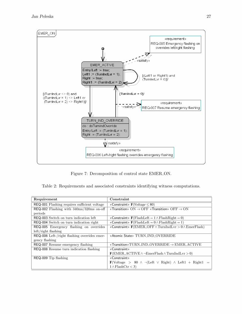
Jan Peleska 27
Figure 7: Decomposition of control state EMER ON.
Table 2: Requirements and associated constraints identifying witness computations.
Requirement Constraint
REQ-001 Flashing requires sufficient voltage «Constraint» F(Voltage≤ 80)
REQ-002 Flashing with 340ms/320ms on-offperiods
«Transition» ON→OFF «Transition» OFF→ON
REQ-003 Switch on turn indication left «Constraint» F(FlashLeft = 1∧FlashRight = 0)
REQ-004 Switch on turn indication right «Constraint» F(FlashLeft = 0∧FlashRight = 1)
REQ-005 Emergency flashing on overridesleft/right flashing
«Constraint» F(EMER OFF∧TurnIndLvr > 0∧EmerFlash)
REQ-006 Left-/right flashing overrides emer-gency flashing
«Atomic State» TURN IND OVERRIDE
REQ-007 Resume emergency flashing «Transition»TURN IND OVERRIDE→ EMER ACTIVE
REQ-008 Resume turn indication flashing «Constraint»F(EMER ACTIVE∧¬EmerFlash∧TurnIndLvr > 0)
REQ-009 Tip flashing «Constraint»F(Voltage > 80 ∧ ¬(Left ∨ Right) ∧ Left1 + Right1 =1∧FlashCtr < 3)

28 Industrial-Strength Model-Based Testing
Figure 8: State machine switching indication lights.
Figure 9: Decomposition of control state FLASHING.
A. Petrenko, H. Schlingloff (Eds.): Eighth Workshop onModel-Based Testing (MBT 2013)EPTCS 111, 2013, pp. 29–29, doi:10.4204/EPTCS.111.2
c© Olga GrinchteinThis work is licensed under theCreative Commons Attribution License.
Model-Based testing for LTE Radio Base Station
Olga GrinchteinEricsson AB, Sweden
The presentation describes experiences of applying model-based testing to LTE Radio Base Station.The presentation shows results from MBT project which was carried out at the organization in Eric-sson, which is responsible for integration and verification of LTE Radio Access Network. The ”LTE,Long Term Evolution, is the next generation mobile network beyond 3G. LTE Radio Access Networkconsists of LTE Radio Base Station, which supports the LTE air interface and performs radio resourcemanagement. The presentation is focused on LTE feature, which requires combinatorial testing. Thepresentation describes what kind of problems we faced during modelling and concretization. Wedescribe benefits and disadvantages of using Spec Explorer tool for modelling and test generation.
A. Petrenko, H. Schlingloff (Eds.): Eighth Workshop onModel-Based Testing (MBT 2013)EPTCS 111, 2013, pp. 30–34, doi:10.4204/EPTCS.111.3
c© Grabowski et al.This work is licensed under theCreative Commons Attribution License.
Towards the Usage of MBT at ETSI
Jens GrabowskiUniversity of Gottingen, Germany
Victor KuliaminISP RAS, Russia
Alain-Georges Vouffo FeudjioThales, Germany
Antal Wu-Hen-ChangEricsson, Hungary
Milan ZoricETSI, France
In 2012 the Specialists Task Force (STF) 442 appointed by the European Telcommunication Stan-dards Institute (ETSI) explored the possibilities of using Model Based Testing (MBT) for test devel-opment in standardization. STF 442 performed two case studies and developed an MBT-methodologyfor ETSI. The case studies were based on the ETSI-standards GeoNetworking protocol (ETSI TS 102636) and the Diameter-based Rx protocol (ETSI TS 129 214). Models have been developed for partsof both standards and four different MBT-tools have been employed for generating test cases fromthe models. The case studies were successful in the sense that all the tools were able to producethe test suites having the same test adequacy as the corresponding manually developed conformancetest suites. The MBT-methodology developed by STF 442 is based on the experiences with the casestudies. It focusses on integrating MBT into the sophisticated standardization process at ETSI. Thispaper summarizes the results of the STF 442 work.
1 Introduction
Driven by technological advances and an ever-growing need for software and systems quality improve-ments, MBT has matured in the last decade from a topic of research into an industrial technology. MBThas been successfully used for the automatic generation of test documentation and test scripts in a widerange of application areas including information and communication technology, embedded systems andmedical software. This trend is reflected by the availability of various commercial tools and increasingefforts in MBT-related standardization. The utilization of MBT in industry show significant gains inproductivity, in particular due to savings in the test maintenance phase.
In 2010, the ETSI Technical Committee (TC) on Methods for Testing and Specification (MTS) pub-lished a first ETSI standard on MBT (ES 202 951) [3] as the result of a joint effort of different stake-holders at ETSI including MBT tool vendors, major users, service providers, and research institutes. Inorder to enable the use of this technology at ETSI, the applicability of MBT in ETSI processes has tobe shown and methodology guidelines for applying MBT in the context of standardized test develop-ment are needed. For this purpose ETSI TC MTS started in 2012 STF 442. STF 442 consists of fiveexperts from industry and academia with 30 working days each. The work was conducted from Febru-ary 2012 to December 2012. STF 442 performed two case studies from the ETSI domains IntelligentTransportation Systems (ITS) and Universal Mobile Telecommunications System (UMTS) and used thegained experience for developing ETSI MBT methodology guidelines.
Grabowski et al. 31
In the following, we present the case studies, describe the methodology and discuss problems en-countered when applying MBT in the case studies.
2 Case Studies
The following four MBT tools have been used for the case studies:
• Conformiq Designer is the MBT tool of Conformiq Inc. [1]. Conformiq models are written in acombination of Java code and UML statecharts, i.e., in the Conformiq Modeling Language (QML).The models describe the expected external behavior of the System Under Test (SUT). Java codeis used to describe the data processing of the SUT, to declare data types and classes, to expressarithmetics and conditional rules as well as others. UML statecharts are used to capture high-levelcontrol flow and life cycle of objects. The core of Conformiq Designer is its semantics driven,symbolic execution based test generation algorithm. The algorithm traverses a part of the (usuallyinfinite) state space of the system model. The test generation heuristics that Conformiq Designeruses realize various well-known test generation strategies, e.g., requirements coverage, transitioncoverage, branch coverage, atomic condition coverage, and boundary value analysis.
• Microsoft Spec Explorer for VisualStudio 2010 is a Microsoft MBT tool [10]. Spec Explorer usesstate-oriented model programs that are coded in C#. Test generation is performed by exploring thestate space of the system model and recording the traces. These traces are transformed into testcases. The main technique for dealing with state space explosion provided by Spec Explorer isscenario-based slicing. A scenario limits the potential executions of the model state graph, whilepreserving the test oracle and other semantic constraints from the system model. Slicing scenariosalong with test data used as input for model operations are defined in the scripting language Cord.
• Sepp.med MBTsuite is the MBT framework from the sepp.med GmbH [11]. For applying MBT-suite, a graphical model of the SUT has to be provided. In our case studies, UML state and activitydiagrams have been used. MBTsuite excutes models and transforms the execution traces into testcases. Apart from full path coverage, other generation strategies are available (e.g. guided gener-ation, random generation). If defined in the model, guard conditions and priorities are taken intoaccount at execution time. Thus, only logically consistent execution traces are obtained and pro-cessed into test cases. It is possible to filter the execution traces prior to test case generation usingseveral built-in heuristics like, e.g., node coverage, edge coverage, requirement coverage, but alsoheuristics based on test management information (costs, duration).
• Fraunhofer MDTester is an academic MBT tool developed by the Fraunhofer FOKUS compe-tence center MOTION [9]. MDTester is part of Fokus!MBT, a flexible and extensible test modelingenvironment based on the UML Testing Profile (UTP), which facilitates the development of model-based testing scenarios for heterogeneous application domains. MDTester is a modeling tool thatguides the development of UTP models. UTP models are test models and not system models, i.e.,they include tester knowledge like, e.g., setting of test verdicts, knowledge about test components,or default behavior. For modeling, MDTester provides the following diagrams types: test require-ments diagram (based on class diagram), test architecture diagram (based on class diagram), testdata diagram (based on class diagram), test architecture diagram, test behavior diagram (based onsequence and activity diagrams).
The case studies were based on ITS and UMTS protocols standardized by ETSI. In addition, STF 442conducted the academic example of a simple automated teller machine to gain experience with the tools.

32 Towards the Usage of MBT at ETSI
For the ITS-based case study, conformance tests for the location service functionality of the GeoNet-working protocol (ETSI TS 102 636) [6] have been generated from previously developed models. TheGeoNetworking protocol belongs to the ITS network layer. The location service functionality is used todiscover units with certain addresses and to maintain data on their geographical location.
The Rx interface (ETSI TS 129 214) [8] of UMTS provides the base for the second case study. TheRx interface supports the transfer of session information and policy/charging data between ApplicationFunction and Policy/Charging Rules Function on top of the Diameter protocol.
In both case studies, the modeled behavior of the System Under Test (SUT) can be described withapproximately 12 control states and a slightly higher number of transitions between them. However, themain complexity of the SUT-model behavior is related to data stored and used during operation. Forthe GeoNetworking case study, this data refers to addresses and geographical locations; whereas sessionsettings and policy rules are most important the behavior of the Rx interface case study.
Two different approaches have been used for modeling. The first approach started from the manu-ally developed test purposes [7, 5] and resulted in SUT-models sufficient to cover all the test purposes,meanwhile adding some more details from standard requirements. The second approach was based onthe requirements in the base standard. The constructed SUT model tried to reflect all of them in theirbehavior. Both approaches were successful in a sense that the models were suitable for test generation.
In spite of the fact the different tools use different formalisms as input for SUT models and providedifferent means to control test generation, all tools managed to generate test suites that cover almost themanually developed test purposes. Thus, from a technical point of view, modern MBT tools are able tosupport test development in standardization.
The case studies are documented in [4]. The report includes detailed descriptions of the SUT behaviorand the models, a discussion of modeling approaches, the generated tests, and overall evaluation.
3 Methodology GuidelinesThe second goal of the STF work was the development of methodology guidelines for an MBT-baseddevelopment of conformance tests at ETSI [2]. ETSI has a very sophisticated test development proce-dure shown on the left side of Figure 1. Test development starts with the identification of requirementsfollowed by the creation of Implementation Conformance Statement (ICS) and Interoperable FunctionStatement (IFS). ICS/IFS define implementation options for a standard. In the testing process, theyare used for test case selection. The ICS/IFS creation is followed by the specification of the test suitestructure, which in most cases arises from the functionality to be tested. Afterwards, high-level test de-scriptions, i.e., test purposes, are stepwise refined leading to the test cases, which are finally validated.The test development steps lead to documents represented by the ellipses in the middle of Figure 1.
The integration of MBT in the ETSI process is shown on the right side of Figure 1. The modelingfor testing is based on standard and requirements. If possible, implementation options (i.e., ICS/IFS)are considered in modeling. The modeling process can be seen as an additional validation step for thestandard, the requirements and the implementation options. Problems in modeling may identify ambi-guities in the standard or untestable requirements. The model serves as input for the test generation.Problems identified during test generation or in the generated tests may identify problematic require-ments or require adaptations in the SUT model. For integrating MBT into the ETSI test developmentprocess, documents describing test suite structure, test purposes, test descriptions and test cases have tobe generated.
Even though this embedding of MBT into the ETSI test development process looks straightforward,several issues need to be solved before MBT can improve the existing process. A main problem is the

Grabowski et al. 33
Figure 1: Using MBT within the ETSI test development process
maintenance and consistency of model and test documents. On the one hand, MBT only requires main-tenance and further development of models while test cases are generated and not manually developed.On the other hand, each test case is an asset and its implementation can be very costly. Reviews anddiscussions are therefore mainly based on individual test descriptions and not on models. Another issueis the selection of a modeling language. Even though all MBT tools used for the case studies allowstate-oriented modeling, the input languages differ considerably. A pragmatic solution to this problemmay include the standardization of an ETSI modeling language.
In addition to issues regarding the test development process, the ETSI MBT methodology guidelinesalso offer guidance for identification and modeling of requirements, establishing traceability from modelsto standard requirements, choosing model scope and abstraction level, selecting test coverage criteria,improving maintainability and parameterization of generated tests, as well as assessing the quality ofmodels and tests.
4 Summary and Conclusions
STF 442 has successfully applied MBT to generate conformance tests for two ETSI protocols. Bothcase studies have been performed with all tools. All tools were able to generate to test suites havingan adequacy level comparable with manually designed tests. Based on the case studies, ETSI MBTmethodology guidelines have been developed. The methodology guidelines focus on integrating MBTinto the standardization process at ETSI. Some challenges have been identified during the STF work:
• An efficient usage of MBT in standardization requires significant expertise in several areas, likee.g., the domain of the SUT, modeling, MBT tool application, and test development. Expertsexperienced in all areas are difficult to find.
• There exists an abstraction gap between automatically generated and manually specified test cases.Manually test cases are usually more maintainable and can be subject of a review. By considering
34 Towards the Usage of MBT at ETSI
parameterization, manually developed test cases allow an easy adaptation to different implemen-tations of a standard. Solving this issue can be seen as a requirement for future MBT tools.
• The conformance test development process at ETSI is tightly intertwined with test suite main-tenance issues and with handling each test case as a separate artifact. Test cases are designedindividually and are subject of discussions and reviews. In contrast to the ETSI process, one ofthe main MBT advantages is the transfer of all maintenance work to the modeling, while tests areconsidered to be generated automatically as often as needed, i.e., maintenance of automaticallygenerated tests is not necessary. For ETSI, taking full advantage of MBT may require new pro-cesses changing from the test case centric development to model standardization and maintenance.
Acknowledgements
The authors thank ETSI TC MTS for supporting the work presented in this paper.
References[1] Conformiq Inc.: Conformiq Inc. products Web page for Conformiq Designer. http://www.conformiq.
com/products/conformiq-designer.[2] ETSI Draft EG 203 130: ”Methods for Testing and Specification (MTS); Model-Based Testing (MBT);
Methodology for standardized test specification development” V.1.1.1 (2013-02).[3] ETSI ES 202 951: ”Methods for Testing and Specification (MTS); Model-Based Testing (MBT); Require-
ments for Modelling Notations” V1.1.1 (2011-07). http://www.etsi.org/deliver/etsi_es/202900_202999/202951/01.01.01_60/es_202951v010101p.pdf.
[4] ETSI TR/MTS 103 133: ”Methods for Testing and Specification (MTS); Model-Based Testing (MBT); Appli-cation of MBT in ETSI case studies” V.1.1.1 (2013-02).
[5] ETSI TS 101 580-2: ”IMS Network Testing (INT); Diameter Conformance testing for Rx interface; Part 2:Test Suite Structure (TSS) and Test Purposes (TP)” V1.1.1 (2012-04). http://www.etsi.org/deliver/
etsi_ts/101500_101599/10158002/01.01.01_60/ts_10158002v010101p.pdf.[6] ETSI TS 102 636-4-1: ”Intelligent Transport Systems (ITS); Vehicular communications; GeoNetworking;
Part 4: Geographical addressing and forwarding for point-to-point and point-to-multipoint communications;Sub-part 1: Media-Independent Functionality ” V1.1.1 (2011-06). http://www.etsi.org/deliver/
etsi_ts/102600_102699/1026360401/01.01.01_60/ts_1026360401v010101p.pdf.[7] ETSI TS 102 871-2: ”Intelligent Transport Systems (ITS); Testing; Conformance test specifications
for GeoNetworking ITS-G5; Part 2: Test Suite Structure and Test Purposes (TSS&TP)” V1.1.1(2011-06). http://www.etsi.org/deliver/etsi_ts/102800_102899/10287102/01.01.01_60/
ts_10287102v010101p.pdf.[8] ETSI TS 129 214: ”Universal Mobile Telecommunications System (UMTS); LTE; Policy and charging control
over Rx reference point” (3GPP TS 29.214) V10.6.0 (2012-03). http://www.etsi.org/deliver/etsi_ts/129200_129299/129214/10.03.00_60/ts_129214v100300p.pdf.
[9] Fraunhofer FOKUS competence center MOTION: MOTION Web page. http://www.fokus.fraunhofer.de/en/motion/index.html.
[10] Microsoft Corporation: Microsoft Developer Network Web pages for Spec Explorer. http://msdn.
microsoft.com/en-us/library/ee620411.[11] sepp.med GmbH: sepp.med products Web page for MBTsuite. http://www.seppmed.de/produkte/
mbtsuite.html.

A. Petrenko, H. Schlingloff (Eds.): Eighth Workshop onModel-Based Testing (MBT 2013)EPTCS 111, 2013, pp. 35–50, doi:10.4204/EPTCS.111.4
c© Isabel Nunes & Filipe LuısThis work is licensed under theCreative Commons Attribution License.
Testing Java implementations of algebraic specifications
Isabel NunesFaculty of Sciences, University of Lisbon
Lisboa, [email protected]
Filipe LuısFaculty of Sciences, University of Lisbon
Lisboa, [email protected]
In this paper we focus on exploiting a specification and the structures that satisfy it, to obtain a meansof comparing implemented and expected behaviours and find the origin of faults in implementations.We present an approach to the creation of tests that are based on those specification-compliant struc-tures, and to the interpretation of those tests’ results leading to the discovery of the method respon-sible for an eventual test failure. Results of comparative experiments with a tool implementing thisapproach are presented.
1 Introduction
The development and verification of software programs against specifications of desired properties isgrowing weight among software engineering methods and tools for promoting software reliability. In par-ticular, finding the software element containing a given fault is highly desirable and several approachesexist that tackle this issue, that can be quite different in the way they approach the problem.
ConGu [14, 15] is both an approach and a tool for the runtime verification of Java implementations ofalgebraic specifications. It verifies that implementations conform to specifications by monitoring methodexecutions in order to find any violation of automatically generated pre and post-conditions.
The ConGu tool [7] picks a module of axiomatic specifications, together with a Java implementationand a refinement that maps specifications to Java types, and responds to an erroneous implementation byoutputing the specification constraint that was violated; this is often insufficient to find the faulty method,because all methods involved in the violated constraint become equally suspect.
A ConGu companion tool – the GenT tool [3, 4] – generates JUnit test cases from ConGu specifi-cations. Generating test cases that are known to be comprehensive, i.e. that cover all constraints of thespecification, as GenT does, is a very important activity, because the confidence we may gain on thecorrection of the software we use greatly depends on it. But, in order for these tests to be of effective use,we should be able to use their results to localize the faulty components. Here again, executing the JUnittests generated by GenT fails to give the programmer clear hints about the faulty method – all methodsused in failed tests are suspect. The ideal result of a test suite execution would be the exact localizationof the fault.
In this paper we enrich ConGu, by giving it the capability of locating the methods that are responsiblefor detected faults. We present a technique that builds upon structures satisfying the specification toobtain a means to observe the implemented behaviour against the intended one, and to locate faultymethods in implementations. Unlike several existing approaches, ours does not inspect the executedcode; instead, it exploits the specification and conforming structures in order to be able to interpret somefailures and discover their origin.
A tool was built – the Flasji tool – that implements the presented technique, and a comparative exper-iment was undertaken to evaluate its results. A summary of these results, which were very encouraging,is presented in this paper.

36 Testing Java implementations of algebraic specifications
user classes.class *
ConGu specs
spec2java mapping
data flowaction flow
Alloy spec testobjects
conform to spec
mock classes.java *
Translate ConGu specs to Alloy spec
fault location
Run Alloy
Analyzer
Create mock
classes
Create test class to compare abstract and
concrete objectsRun test
Interpret the
results
Figure 1: Overview of the Flasji approach.
The unit of fault Flasji is able to detect is the method, leaving to the programmer the task of identi-fying the exact instruction within it that is faulty. If more than one fault exists, the repeated applicationof the process, together with the correction of the identified faulty method, should be adopted. In whatconcerns integration testing strategy, Flasji applies an incremental one in the sense that the Java typesimplementing the specification are not tested all together; instead, each one is tested conditionally, pre-suming all others from which it depends are correctly implemented. This incremental integration ispossible since the overall specification is given as a structured collection of individual specifications(a ConGu module), whose structure is matched by the structure of the Java collection of classes thatimplements it.
The remainder of the paper is organized as follows: section 2 introduces the ConGu specificationlanguage through an example that will be used throughout the paper, and gives an overview of the Flasjiapproach; section 3 details every Flasji step, from picking a specification module and correspondingimplementation, to the identification of the faulty method, explaining the several items Flasji produces;an evaluation experiment of the Flasji tool is presented in section 4 where results are compared with theones obtained using two other tools; in section 5 we focus our discussion on relevant aspects related tothe work presented in this paper; finally, section 6 concludes.
2 Approach Overview
In this section we give a general overview of the Flasji approach. An example is introduced that will beused throughout the paper.
2.1 The approach in a nutshell
As illustrated in figure 1, the Flasji approach integrates a series of steps from an initial input comprisinga module of ConGu specifications and corresponding Java implementations (together with a mappingdefining correspondences between the two), to a final output comprising the method identified as theone containing the fault, whenever possible, and a list of other methods suspect of being faulty. The
Isabel Nunes & Filipe Luıs 37
whole process leading from the initial input to the final output is automated, without any further userintervention.
The main strategy underlying the Flasji process is the comparison between what we call “abstract”and “concrete” objects; the former are objects that are well-behaved in the sense that they conformto the specification, while the latter are objects that behave according to the classes implementing thespecification, which we want to investigate for faults.
We capitalize on the Alloy Analyzer [1] tool which is capable of finding structures that satisfy acollection of constraints – a specification. The specifications this tool works with are written in theAlloy [11] language.
Flasji begins by translating the ConGu specification module into an Alloy specification, in orderto be able to, in a posterior phase, generate structures satisfying it. It then creates Java classes whoseinstances will represent objects satisfying the specification (the “abstract” objects) – these classes arecalled “mock” classes; in order for “abstract” objects to represent structures that satisfy the specification,they are given the ability of storing and retrieving the results of applying each and every operation of thespecification, as will be seen later.
A third step feeds the Alloy Analyzer tool with the specification, asking the tool for a collection ofstructures satisfying the specification. This collection will be used in the next step to define the abstractobjects, which will present the expected, correct, behaviours.
In a fourth step, a test class is created that contains instructions to instantiate both the mock classesand the implementation classes given as input, and to compare the behaviour of the “concrete” objectsagainst the “abstract” ones, in order to identify the faulty method. Flasji then executes this test class andinterprets its results to obtain the faulty method.
Remember that all these steps are automatically processed, thus transparent to the Flasji user. Sec-tion 3 describes them in detail.
2.2 A specification and corresponding implementation
Simple sorts, sub-sorts and parameterized sorts can be specified with the ConGu specification language,and mappings between those sorts and Java types, and between those sorts’ operations and Java methods,can be defined using the ConGu refinement language.
We present a classical yet rich example, of a ConGu specification of the SortedSet parameterizeddata type, representing a set of Orderable elements, together with the specification for its parameter(figure 2).
In a specification, we define constructors, observers and other operations, where constructors com-pose the minimal set of operations that allow to build all instances of the sort, observers can be usedto analyse those instances, and the other operations are usually comparison operations or operations de-rived from the others; depending on whether they have an argument of the sort under specification (selfargument) or not, constructors are classified as transformers or creators (transformers are also referredto as non-creator constructors).
All operations that are not constructors must have a self argument. Any function can be partial (de-noted by→?), in which case a domains section specifies the conditions that restrict their domain. Axiomsdefine every value of the type through the application of observers to constructors – see, e.g., the axiomisEmpty(empty()); that specifies that the result of applying the observer operation isEmpty to a SortedSetinstance obtained with the creator constructor empty is true, and the axiom not isEmpty(insert(S, E));saying that the result of applying isEmpty to any SortedSet instance to which the transformer constructor

38 Testing Java implementations of algebraic specifications
specification SortedSet[TotalOrder] sorts SortedSet[Orderable] constructors empty: --> SortedSet[Orderable]; insert: SortedSet[Orderable] Orderable --> SortedSet[Orderable]; observers isEmpty: SortedSet[Orderable]; isIn: SortedSet[Orderable] Orderable; largest: SortedSet[Orderable] -->? Orderable; ... domains S: SortedSet[Orderable]; largest(S) if not isEmpty(S); axioms E, F: Orderable; S: SortedSet[Orderable]; isEmpty(empty()); not isEmpty(insert(S, E)); not isIn(empty(), E); isIn(insert(S,E), F) iff E = F or isIn(S, F); largest(insert(S, E)) = E if isEmpty(S); largest(insert(S, E)) = E if not isEmpty(S) and geq(E, largest(S)); largest(insert(S, E)) = largest(S) if not isEmpty(S) and not geq(E, largest(S)); ...end specification
specification TotalOrder sorts Orderable observers geq: Orderable Orderable; axioms E, F, G: Orderable; E = F if geq(E, F) and geq(F ,E); geq(E, F) if E = F; ... end specification
Figure 2: Parts of the ConGu specifications for the SortedSet parameterized data type and its parameter.
public interface IOrderable<E> {boolean greaterEq(E e);
}
public class TreeSet<E extends IOrderable<E>> {public TreeSet() {...}public void insert(E e) {...}public boolean isEmpty() {...}public boolean isIn(E e) {...}public E largest() {...}...
}
Figure 3: Excerpt from a Java implementation of the ConGu specification for SortedSet.
insert has been applied is false .Generic Java class TreeSet in figure 3 represents a Java implementation of the SortedSet param-
eterized data type; in the same figure, interface IOrderable represents a Java type restraining theTreeSet parameter. We want to investigate the TreeSet class for faults, independent of any specificimplementation of its parameter type.
The correspondence between ConGu and Java types must be defined in order for implementationsto be checked. This correspondence is described in terms of refinement mappings; figure 4 shows arefinement mapping from the specifications SortedSet and TotalOrder (figure 2) to Java types TreeSetand IOrderable (figure 3).
These mappings associate ConGu sorts and operations to Java types and corresponding methods.The insert operation of sort SortedSet is mapped to the TreeSet class method with the same namewith the signature void insert(E e). Notice that the TotalOrder parameter sort is mapped to a Javatype variable that is used as the parameter of the generic TreeSet implementation; this specific mappingis interpreted as constraining any instantiation of the TreeSet parameter to a Java type Some containinga method with signature boolean greaterEq(Some e).
Detailed information about the ConGu approach can be found in [14, 15].

Isabel Nunes & Filipe Luıs 39
refinement <E> SortedSet[TotalOrder] is TreeSet<E> { empty: --> SortedSet[Orderable] is TreeSet(); insert: SortedSet[Orderable] e:Orderable --> SortedSet[Orderable] is void insert(E e); ... } TotalOrder is E { geq: Orderable e:Orderable is boolean greaterEq(E e); }end refinement
Figure 4: Refinement mapping from ConGu specifications to Java types.
3 Flasji step-by-step
As already said in the previous section, the main goal of the Flasji approach is to verify whether “con-crete” Java objects behave the same as corresponding “abstract” ones; the deviations to the expectedbehaviour are interpreted in order to find the location of the faulty method.
Only one of the implementing classes is under verification – the core type, that is, the one thatimplements the core sort –, which is the one at the root of the class association graph (the TreeSet
class in the example). Thus, both “abstract” and “concrete” objects will be created for this type, in orderto compare behaviours. This does not apply for non-core types since they are not under verification.However, as we shall see, “abstract” parameter objects must be created.
Let us now detail the several steps of the Flasji approach.
3.1 Translating the ConGu specification module
Flasji creates an Alloy specification equivalent to the ConGu specification module, in order to be able,ahead in the process, to obtain a collection of objects that conform to the specification, thus definingexpected, correct behaviour.
This step capitalizes on already existing work, referred to in the introduction of this paper, namelythe GenT tool [3, 4], of which Flasji uses the ConGuToAlloy module.
3.2 Creating mock classes
Flasji creates mock classes for the Java types implementing the specification core and parameter sorts;these classes’ instances will represent the “abstract” objects. In the running example, two mock classesmust be created, one corresponding to the TreeSet class – TreeSetMock –, and other correspondingto the IOrderable interface – OrderableMock.
This mock class will be used to generate parameter objects that will be inserted not only in “ab-stract” sorted sets (TreeSetMock instances as explained below), but also in “concrete” ones (TreeSetinstances); the idea, as said before, is to test the implementation of the core signature for any parameterinstantiation that correctly implements the Orderable sort.
Each instance of a mock class defines an object conforming to the specification, including its “be-haviour”, that is, the results of applying to it all the operations of the type (respecting the correspondingdomain conditions). Since we only compare “abstract” and “concrete” objects of the core type, funda-mental differences exist between the mock class for this core type and the others. Let us see first themock class for the Orderable parameter of the running example, which is a non-core type.

40 Testing Java implementations of algebraic specifications
1 public class OrderableMock implements IOrderable〈OrderableMock〉{2 private HashMap〈OrderableMock, Boolean〉 greaterEqResult = new HashMap〈OrderableMock,
Boolean〉();3 public boolean greaterEq(OrderableMock e) {4 return greaterEqResult.get(e);}5 public void add_greaterEq(OrderableMock e, Boolean result) {6 greaterEqResult.put(e, result);7 }8 }
Listing 1: Mock class corresponding to the Orderable parameter sort.
For each method X corresponding to a specification operation X, an attribute is defined to keep theinformation about the results of X, for every combination of the method’s parameters (see line 2 for themethod greaterEq in interface Iorderable, corresponding to operation geq in sort Orderable); theadd_X method “fills” that attribute (lines 5 and 6), and the X method retrieves the result for given valuesof the method’s parameters (lines 3 and 4).
The class that represents “abstract” objects of the core type (class TreeSetMock in the example)is also generated. The idea here is not to use these “abstract” objects on both abstract and concretecontexts, as we do with parameter ones, but to use them to inform us, for every operation, of the resultswe should expect when applying corresponding methods to corresponding “concrete” objects in order toverify whether the latter behave as they should.
The fundamental difference lies in the information that core type “abstract” objects keep for opera-tions whose result is of the core type ( insert in the example). Since we want to be able to know whetherthe “concrete” TreeSet object that results from applying the insert method of the TreeSet class toa “concrete” object concObj is the correct one, we give the corresponding “abstract” object absObjinformation that allows us to verify it – we “feed” absObj with the “concrete” object that should beexpected when applying that operation. Ahead in this paper we show how this is achieved; for now, wejust present the TreeSetMock mock class in listing 2, where attribute and methods in lines 19 to 24allow “abstract” objects to keep and inform about “concrete”, expected results of applying insert fordifferent values of the method’s parameter:
1 public class TreeSetMock 〈T〉{2
3 // operations whose result is of a non-core type4 private HashMap〈T,Boolean〉 isInResult = new HashMap〈T,Boolean〉();5 private boolean isEmptyResult;6 private T largestResult;7
8 public boolean isIn (T e){return isInResult.get(e);}9 public void add_isIn (T e, Boolean result){
10 isinResult.put(e, result);}11 public boolean isEmpty(){return isEmptyResult;}12 public void add_isEmpty(boolean result){13 isEmptyResult = result;}14 public T largest(){return largestResult;}15 public void add_largest(T result){16 largestResult = result;}17
18 // operation whose result is of the core type19 private HashMap〈T,TreeSet〈T〉 〉 insertResult = new HashMap〈T,TreeSet〈T〉 〉 ();20
21 public TreeSet〈T〉 insert (T e){22 return insertResult.get(e); }23 public void add_insert (T e, TreeSet〈T〉 concVal){24 insertResult.put(e, concVal); }

Isabel Nunes & Filipe Luıs 41
25 }
Listing 2: Mock class corresponding to the SortedSet sort.
Line 19 declares and initializes the attribute that will store the information about the results of methodinsert – for each value of the parameter T e, it will store a “concrete” object. Methods insert andadd_insert, in lines 21 to 24, allow to retrieve and define, respectively, the result of insert for everyvalue of the operation’s parameter.
Figure 5: A structure satisfying the SortedSet specification module, found by the Alloy Analyzer.
3.3 Obtaining a collection of instances satisfying the specification
In order to obtain a collection of instances of the specification sorts that conform to our specification,Flasji capitalizes on the Alloy Analyzer tool [11] which, if such a finite collection exists, is capable ofgenerating it (such a finite collection does not exist e.g. in the case of a specification of an unboundedstack).
The results presented in this paper assume Flasji asks the Alloy Analyzer to generate a structurewith a fixed number of objects of the core type; work is under way to optimize the determination of thenumber of objects that should be considered of each type.
Figure 5 shows an example for the SortedSet specification. This collection consists of 2 Orderableinstances and 4 SortedSet ones. The result of every applicable operation is defined for each of theseinstances (e.g. SortedSet2 contains the two Orderables, and it is obtained by inserting Orderable0 intoSortedSet0 or else from inserting Orderable1 into SortedSet1).
These instances define correct, expected behaviour; in the next steps, Flasji will use the non-coresort ones (Orderable instances in the example) to create mock “abstract” objects that will represent well-

42 Testing Java implementations of algebraic specifications
behaved objects, and uses the core sort ones (SortedSet instances in the example) to create mock “ab-stract” objects (TreeSetMock and “concrete” corresponding ones (TreeSet instances in the example)instances in the example) that will be compared. Let us see how.
3.4 Creating the test class
Flasji generates a test class containing instructions to:1. create “abstract” objects corresponding to the objects composing the Alloy structure that conforms
to the specification;
2. create “concrete” objects of the core type that correspond to the “abstract” ones (by using thecorresponding concrete constructors); and
3. compare the behaviour of these “abstract” and “concrete” objects, by observing them in equalcircumstances, that is, by applying corresponding methods and comparing the results.
By compiling and executing this test class, Flasji will be able to get information that it will interpretin order to find the faulty method, as explained ahead. First let us see how Flasji acomplishes this testclass creation task.
3.4.1 Creating abstract objects
Listing 3 shows part of the generated test class, namely the creation of the “abstract” objects accordingto the Alloy structure defined in figure 5: two OrderableMock instances (lines 4 and 5) and fourTreeSetMock ones (lines 11 to 14).
Lines 6 to 9 show OrderableMock objects being initialized – because the only method of thistype is greaterEq, only the method add_greaterEq is invoked over each “abstract” object, for everypossible value of its parameter, in order to give these objects the information about the expected, correct,results.
We postpone the initialization of the TreeSetMock objects because it implies previous creation ofthe corresponding concrete objects.
1 @Test2 public void abstractVSconcreteTest () {3 //IOrderable Mocks4 OrderableMock orderable0 = new OrderableMock();5 OrderableMock orderable1 = new OrderableMock();6 orderable0.add_greaterEq(orderable0, true);7 orderable0.add_greaterEq(orderable1, true);8 orderable1.add_greaterEq(orderable0, false);9 orderable1.add_greaterEq(orderable1, true);
10 //Abstract objects TreeSet11 TreeSetMock 〈OrderableMock〉 sortedSet3 = new TreeSetMock 〈OrderableMock〉();12 TreeSetMock 〈OrderableMock〉 sortedSet0 = new ...;13 TreeSetMock 〈OrderableMock〉 sortedSet1 = new ...;14 TreeSetMock 〈OrderableMock〉 sortedSet2 = new ...;
Listing 3: (Part of) the test class – building the “abstract” objects (incomplete).
3.4.2 Creating concrete objects
Flasji also builds “concrete” objects for the core sort. For each “abstract” object of the core sort there willexist a corresponding “concrete” one, which will be built using the corresponding constructor methods(see listing 4).
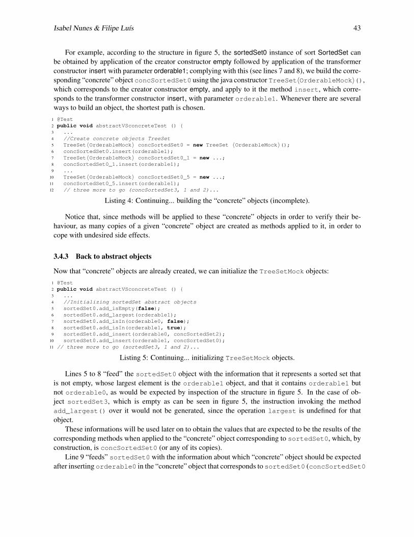
Isabel Nunes & Filipe Luıs 43
For example, according to the structure in figure 5, the sortedSet0 instance of sort SortedSet canbe obtained by application of the creator constructor empty followed by application of the transformerconstructor insert with parameter orderable1; complying with this (see lines 7 and 8), we build the corre-sponding “concrete” object concSortedSet0 using the java constructor TreeSet〈OrderableMock〉(),which corresponds to the creator constructor empty, and apply to it the method insert, which corre-sponds to the transformer constructor insert , with parameter orderable1. Whenever there are severalways to build an object, the shortest path is chosen.
1 @Test2 public void abstractVSconcreteTest () {3 ...4 //Create concrete objects TreeSet5 TreeSet〈OrderableMock〉 concSortedSet0 = new TreeSet 〈OrderableMock〉();6 concSortedSet0.insert(orderable1);7 TreeSet〈OrderableMock〉 concSortedSet0_1 = new ...;8 concSortedSet0_1.insert(orderable1);9 ...
10 TreeSet〈OrderableMock〉 concSortedSet0_5 = new ...;11 concSortedSet0_5.insert(orderable1);12 // three more to go (concSortedSet3, 1 and 2)...
Listing 4: Continuing... building the “concrete” objects (incomplete).
Notice that, since methods will be applied to these “concrete” objects in order to verify their be-haviour, as many copies of a given “concrete” object are created as methods applied to it, in order tocope with undesired side effects.
3.4.3 Back to abstract objects
Now that “concrete” objects are already created, we can initialize the TreeSetMock objects:1 @Test2 public void abstractVSconcreteTest () {3 ...4 //Initializing sortedSet abstract objects5 sortedSet0.add_isEmpty(false);6 sortedSet0.add_largest(orderable1);7 sortedSet0.add_isIn(orderable0, false);8 sortedSet0.add_isIn(orderable1, true);9 sortedSet0.add_insert(orderable0, concSortedSet2);
10 sortedSet0.add_insert(orderable1, concSortedSet0);11 // three more to go (sortedSet3, 1 and 2)...
Listing 5: Continuing... initializing TreeSetMock objects.
Lines 5 to 8 “feed” the sortedSet0 object with the information that it represents a sorted set thatis not empty, whose largest element is the orderable1 object, and that it contains orderable1 butnot orderable0, as would be expected by inspection of the structure in figure 5. In the case of ob-ject sortedSet3, which is empty as can be seen in figure 5, the instruction invoking the methodadd_largest() over it would not be generated, since the operation largest is undefined for thatobject.
These informations will be used later on to obtain the values that are expected to be the results of thecorresponding methods when applied to the “concrete” object corresponding to sortedSet0, which, byconstruction, is concSortedSet0 (or any of its copies).
Line 9 “feeds” sortedSet0 with the information about which “concrete” object should be expectedafter inserting orderable0 in the “concrete” object that corresponds to sortedSet0 (concSortedSet0
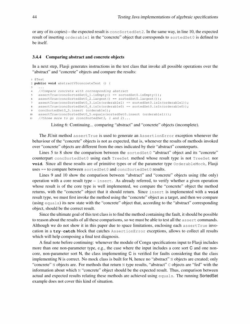
44 Testing Java implementations of algebraic specifications
or any of its copies) – the expected result is concSortedSet2. In the same way, in line 10, the expectedresult of inserting orderable1 in the “concrete” object that corresponds to sortedSet0 is defined tobe itself.
3.4.4 Comparing abstract and concrete objects
In a next step, Flasji generates instructions in the test class that invoke all possible operations over the“abstract” and “concrete” objects and compare the results:
1 @Test2 public void abstractVSconcreteTest () {3 ...4 //Compare concrete with corresponding abstract5 assertTrue(concSortedSet0_1.isEmpty() == sortedSet0.isEmpty());6 assertTrue(concSortedSet0_2.largest() == sortedSet0.largest());7 assertTrue(concSortedSet0_3.isIn(orderable1) == sortedSet0.isIn(orderable1));8 assertTrue(concSortedSet0_4.isIn(orderable0) == sortedSet0.isIn(orderable0));9 concSortedSet0_5.insert (orderable1);
10 assertTrue(concSortedSet0_5.equals(sortedSet0.insert (orderable1)));11 //three more to go (concSortedSet3, 1 and 2)...
Listing 6: Continuing... comparing “abstract” and “concrete” objects (incomplete).
The JUnit method assertTrue is used to generate an AssertionError exception whenever thebehaviour of the “concrete” objects is not as expected, that is, whenever the results of methods invokedover “concrete” objects are different from the ones indicated by their “abstract” counterparts.
Lines 5 to 8 show the comparison between the sortedSet0 “abstract” object and its “concrete”counterpart concSortedSet0 using each TreeSet method whose result type is not TreeSet norvoid. Since all these results are of primitive types or of the parameter type OrderableMock, Flasjiuses == to compare between sortedSet0 and concSortedSet0 results.
Lines 9 and 10 show the comparison between “abstract” and “concrete” objects using (the only)operation with a core result type – insert. As already referred, to verify whether a given operationwhose result is of the core type is well implemented, we compare the “concrete” object the methodreturns, with the “concrete” object that it should return. Since insert is implemented with a voidresult type, we must first invoke the method using the “concrete” object as a target, and then we compare(using equals) its new state with the “concrete” object that, according to the “abstract” correspondingobject, should be the correct result.
Since the ultimate goal of this test class is to find the method containing the fault, it should be possibleto reason about the results of all these comparisons, so we must be able to test all the assert commands.Although we do not show it in this paper due to space limitations, enclosing each assertTrue invo-cation in a try-catch block that catches AssertionError exceptions, allows to collect all resultswhich will help composing a final test diagnosis.
A final note before continuing: whenever the module of Congu specifications input to Flasji includesmore than one non-parameter type, e.g., the case where the input includes a core sort C and one non-core, non-parameter sort N, the class implementing C is verified for faults considering that the classimplementing N is correct. No mock class is built for N, hence no “abstract” N objects are created; only“concrete” N objects are. For methods that return N type results, “abstract” C objects are “fed” with theinformation about which N “concrete” object should be the expected result. Thus, comparison betweenactual and expected results relating these methods are achieved using equals. The running SortedSetexample does not cover this kind of situation.

Isabel Nunes & Filipe Luıs 45
3.5 Running the test and interpreting the results
As soon as the test class is generated, Flasji compiles it and executes it. Then, it interprets the results ofthe tests. The interpretation is based upon the following observations:
1. whether several and varied observers (non-constructor operations) fail or only one fails – this isimportant to decide whether to blame a constructor or a given, specific, observer;
2. whether varied observers fail when applied to “concrete” objects created only by the constructor-creator, or when applied to objects that were also the target of non-creator constructors – this isimportant to decide which constructor is the faulty one.
The result interpretation algorithm inspects three data structures containing data collected during theexecution of the test (whenever an assertTrue command fails):
• L1 - Set of pairs < obs;ob j > that register that differences occurred between expected and actualbehaviour, for given observer obs and object ob j;
• L2 - Set of pairs < ncc;ob j > that register that differences occurred between expected and actualbehaviour, for given non-creator (transformer) constructor ncc and object ob j;
• L3 - Set of pairs < cc;n > that register for every creator constructor cc the number of failedobservations over objects uniquely built with cc;
If, when applied to concrete objects, more than one observer methods present results that are differentfrom the ones expected ((L1 ∪ L2) contains pairs for more than one observer), we may infer that themethod(s) used to build those concrete objects are ill-implemented, and that the problem does not comefrom some particular way of inspecting the objects. If the implementation of a given observer is wrong,one would not expect problems when inspecting the objects using the other observers, but only in theobservations involving that particular one.
If a constructor-creator cc (in the running example, TreeSet() is the cc that implements the emptycreator operation) is faulty, it is reasonable to think that the application of the other constructors over anobject created with cc will most probably result in non-conformant objects, because the initial object isalready ill-built. The information in L3 allows us to focus on creator-constructors.
When no problems arise when observing a freshly created object, but they do arise when observ-ing those objects after being affected by a given non-creator constructor ncc (insert in the runningexample), then one may point the finger to ncc.
if (L1∪L2) contains pairs for more than 1 observer, thenif there exists < cc, i > in L3 with i > 0, then
if that pair < cc, i > with i > 0 is unique, thencc is guilty;
elseinconclusive;
endIfelse
for each non-creator constructor ncc j doLncc j← sub-set of L2 containing only pairs from L2 whose first element is ncc j;Delete from Lncc j the pairs whose ob j was not built using only ncc j and a creator constructor;if Lncc j is not empty, then

46 Testing Java implementations of algebraic specifications
add ncc j to the final set of suspects (FSS);endIf
endForendIfif #FSS = 1 then
the guilty is the sole element of FSS;else
inconclusive;endIf
elseif (L1∪L2) is empty, then
inconclusive;else
the guilty is the sole observer in (L1∪L2);endIf
endIfIf the algorithm elects a guilty method in the end, then the user is given the identified method as the
most probable guilty. In either case, the set FSS of (other) suspects is presented.
4 Evaluation
To evaluate the effectiveness of our approach, we applied it to two case studies – this paper’s SortedSetrunning example, and a MapChain specification module and corresponding implementations. The Javaclasses implementing the designated sorts of both case studies where seeded with faults covering all thespecification operations.
We put Flasji to run for every defective class, and registered the outputs.We also tested those defective classes in the context of two existing fault-location tools – GZoltar [2,
17] and EzUnit4 [5, 18] –, that give as output a list of methods suspect of containing the fault, rankedby probability of being faulty. The tests suites we used were generated by the GenT [3, 4] tool (alreadyreferred to in this paper), from the ConGu specifications and refinement mappings; under given restric-tions (e.g., the specification has finite models) GenT generates comprehensive test suites, that cover allspecification axioms. GenT generated 20 test cases for the SortedSet case, and 17 for the MapChain one.
Finally we compared the three tools’ results for every defective variation of each case study.For each of the defective versions of the designated sorts implementations (for example, two different
faults were seeded in SortedSet isEmpty method, three in MapChain get method, etc) table 1 shows:• the number of tests (among the 20 JUnit tests that were generated by GenT for the SortedSet case,
and 17 for the MapChain one) that failed when both GZoltar and EzUnit4 run them;
• whether the faulty method was ranked, by each tool, as most probable guilty (1st), second mostprobable guilty (2nd) or third or less probable (nth). A fourth type of result – “No” – means theguilty method has not been ranked as suspect at all.
Flasji provided very accurate results in general (see also a summary in figure 6). The bad results inthe three faults for method get of the MapChain case study (there were no suspects found whatsoever)are due to the fact that equals uses the get method, therefore becoming unreliable whenever methodget is faulty. This case exemplifies the oracle problem (see section 5).
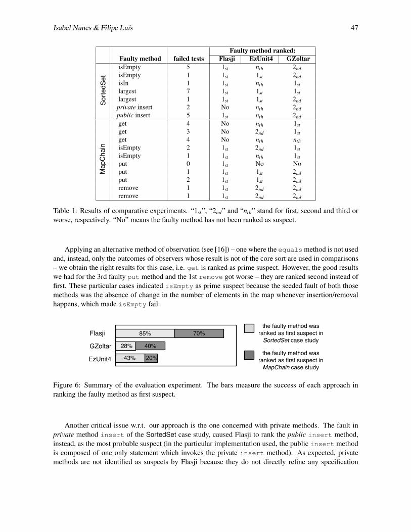
Isabel Nunes & Filipe Luıs 47
Faulty method ranked:Faulty method failed tests Flasji EzUnit4 GZoltar
Sor
tedS
et
isEmpty 5 1st nth 2ndisEmpty 1 1st 1st 2ndisIn 1 1st nth 1stlargest 7 1st 1st 1stlargest 1 1st 1st 2ndprivate insert 2 No nth 2ndpublic insert 5 1st nth 2nd
Map
Cha
in
get 4 No nth 1stget 3 No 2nd 1stget 4 No nth nthisEmpty 2 1st 2nd 1stisEmpty 1 1st nth 1stput 0 1st No Noput 1 1st 1st 2ndput 2 1st 1st 2ndremove 1 1st 2nd 2ndremove 1 1st 2nd 2nd
Table 1: Results of comparative experiments. “1st”, “2nd” and “nth” stand for first, second and third orworse, respectively. “No” means the faulty method has not been ranked as suspect.
Applying an alternative method of observation (see [16]) – one where the equals method is not usedand, instead, only the outcomes of observers whose result is not of the core sort are used in comparisons– we obtain the right results for this case, i.e. get is ranked as prime suspect. However, the good resultswe had for the 3rd faulty put method and the 1st remove got worse – they are ranked second instead offirst. These particular cases indicated isEmpty as prime suspect because the seeded fault of both thosemethods was the absence of change in the number of elements in the map whenever insertion/removalhappens, which made isEmpty fail.
85% 70%
28% 40%
43% 20%
Flasji
GZoltar
EzUnit4
the faulty method wasranked as first suspect inSortedSet case study
the faulty method wasranked as first suspect inMapChain case study
Figure 6: Summary of the evaluation experiment. The bars measure the success of each approach inranking the faulty method as first suspect.
Another critical issue w.r.t. our approach is the one concerned with private methods. The fault inprivate method insert of the SortedSet case study, caused Flasji to rank the public insert method,instead, as the most probable suspect (in the particular implementation used, the public insert methodis composed of one only statement which invokes the private insert method). As expected, privatemethods are not identified as suspects by Flasji because they do not directly refine any specification
48 Testing Java implementations of algebraic specifications
operation (as defined in the refinement mapping from specifications to implementations); instead, thepublic, specified, methods that invoke them are identified.
A case worth mentioning is the one corresponding to the first seeded fault in the put method ofthe MapChain case study, where none of the seventeen GenT tests fail (the particular case that causesthe error was not covered). As a consequence, neither EzUnit4 and GZoltar detected the fault; on thecontrary, Flasji succeeded in detecting the guilty method.
5 Related work
The approach presented in this paper relies on the existence of structures satisfying the specificationto supply the behaviour of objects to be used in tests. The structured nature of specifications, wherefunctions and axioms are defined sort by sort, and where the latter are independently implemented bygiven Java types, is essential to the incremental integration style of Flasji.
Several approaches to testing implementations of algebraic specifications exist, that cover test gen-eration ([6, 8, 9, 10, 12] to name a few), and many compare the two sides of equations where variableshave been substituted by ground terms – differences exist in the way ground terms are generated, and inthe way comparisons are made. The gap between algebraic specifications and implementations makesthe comparison between concrete objects difficult, giving rise to what is known as the oracle problem,more specifically, the search for reliable decision procedures to compare results computed by the imple-mentation. Whenever one cannot rely on the equals method, there should be another way to investi-gate equality between concrete objects. Several works have been proposed that deal with this problem,e.g. [9, 13, 19]. In [16] we tackle this issue by presenting an alternative way of comparing concreteobjects, one that relies only in observers whose result is of a non-core sort. In some way this complieswith the notion of observable contexts in [9] – all observers but the ones whose result is of the designatedsort constitute observable contexts.
The unreliability of equals can also affect the effectiveness of the GenT tests [3] since this methodis used whenever concrete objects of the same type are compared. One of the improvements we intendto make is to give Flasji the ability to test the equals method in order to make its use more reliable.
6 Conclusions
We presented Flasji, a technique whose goal is to test Java implementations of algebraic specificationsand find the method that is responsible for some deviation of the expected behaviour.
Flasji capitalyzes on ConGu, namely using ConGu specification and refinement languages, and en-riches it with the capability of finding faulty methods. It accomplishes the task through the generationof tests that are based on structures satisfying the specification. The behaviour of instances of the imple-mentation is compared with the one expected, as given by those specification-compliant structures. Theresults of the comparisons are interpreted in order to find the method responsible for the fault.
An evaluation experiment was presented where Flasji results over two case studies, for which faultshave been seeded in the implementing Java classes, are compared with two other tools’ results whenexecuted over comprehensive suites of tests. The encouraging results obtained in comparative studiesled us to continue working on it, with the purpose of improving some negative aspects and weaknesses,some of which already identified and reported in this paper.
The following improvements, among others, are planned: (i) testing the implementation of theequals method, even if the specification module does not specify it, in order to be able to better rely on
Isabel Nunes & Filipe Luıs 49
its results, (ii) optimizing the determination of the number of objects of each type that an Alloy structureconforming to the specification should contain (the results here presented assumed Flasji asks the AlloyAnalyzer to generate a structure with a fixed number of objects of the core type), and (iii) whenever thereare several non-parameter types, apply the process several times, each considering one of them as thecore type, and integrate the results (special cases as e.g. inter-dependent types, deserve attention).
References
[1] Alloy Analyzer. http://alloy.mit.edu/alloy/.
[2] R. Abreu, P. Zoeteweij & A.J.C. van Gemund (2009): Spectrum-based Multiple Fault Localization. In: Proc.24th IEEE/ACM ASE, IEEE Computer Society, pp. 88–99, doi:10.1109/ASE.2009.25.
[3] F.R. Andrade, J.P. Faria, A. Lopes & A.C.R. Paiva (2012): Specification-Driven Unit Test Generation forJava Generic Classes. In: IFM 2012, LNCS 7321, Springer-Verlag, pp. 296–311, doi:10.1007/978-3-642-30729-4.
[4] F.R. Andrade, J.P. Faria & A. Paiva (2011): Test Generation from Bounded Algebraic Specifications usingAlloy. In: Proc. ICSOFT 2011, 2, SciTePress, pp. 192–200.
[5] P. Bouillon, J. Krinke, N. Meyer & F. Steimann (2007): EzUnit: A Framework for associating failed unittests with potential programming errors. In: 8th XP, LNCS 4536, Springer, pp. 101–104, doi:10.1007/978-3-540-73101-6 14.
[6] K. Claessen & J. Hughes (2000): QuickCheck: A Lightweight Tool for Random Testing of Haskell Programs.In: Proc. of ICFP, ACM SIGPLAN Notices, pp. 268–279, doi:10.1145/351240.351266.
[7] P. Crispim, A. Lopes & V. Vasconcelos (2011): Runtime verification for generic classes with ConGu2. In:Proc. SBMF 2010, LNCS 6527, Springer-Verlag, pp. 33–48, doi:10.1007/978-3-642-19829-8 3.
[8] R.K. Doong & P.G. Frankl (1994): The ASTOOT Approach to Testing Object-Oriented Programs. ACMTOSEM 3(2), pp. 101–130, doi:10.1145/192218.192221.
[9] M.C. Gaudel & P.L. Gall (2008): Testing data types implementations from algebraic specifications. FormalMethods and Testing, doi:10.1007/978-3-540-78917-8 7.
[10] M. Hughes & D. Stotts (1996): Daistish: systematic algebraic testing for OO programs in the presence ofside-effects. In: Proc. ISSTA96, ACM Press, pp. 53–61, doi:10.1145/229000.226301.
[11] D. Jackson (2012): Software Abstractions - Logic, Language, and Analysis, Revised Edition. MIT Press.
[12] L. Kong, H. Zhu & B. Zhou (2007): Automated Testing EJB Components Based on Algebraic Specifications.In: COMPSAC 2007, pp. 717–722, doi:10.1109/COMPSAC.2007.82.
[13] P.D.L. Machado & D. Sanella (2002): Unit testing for CASL architectural specifications. In: Proc. 27thMFCS, LNCS 2420, Springer, pp. 506–518, doi:10.1007/3-540-45687-2 42.
[14] I. Nunes, A. Lopes & V. Vasconcelos (2009): Bridging the Gap between Algebraic Specification andObject-Oriented Generic Programming. In: Runtime Verification, LNCS 5779, Springer, pp. 115–131,doi:10.1007/978-3-642-04694-0 9.
[15] I. Nunes, A. Lopes, V. Vasconcelos, J. Abreu & L. Reis (2006): Checking the conformance of Javaclasses against algebraic specifications. In: Proc. 8th ICFEM, LNCS 4260, Springer, pp. 494–513,doi:10.1007/11901433 27.
[16] I. Nunes & F. Luıs (2012): A fault-location technique for Java implementations of algebraic specifications.Technical Report 02, Faculty of Sciences of the University of Lisbon.
[17] A. Riboira & R. Abreu (2010): The GZoltar Project: A Graphical Debugger Interface. In L. Bottaci &G. Fraser, editors: TAIC PART, LNCS 6303, Springer, pp. 215–218. Available at http://dx.doi.org/10.1007/978-3-642-15585-7_25.

50 Testing Java implementations of algebraic specifications
[18] F. Steimann & M. Bertschler (2009): A simple coverage-based locator for multiple faults. In: IEEE ICST,LNCS 4536, Springer, pp. 366–375, doi:10.1109/ICST.2009.24.
[19] H. Zhu (2003): A note on test oracles and semantics of algebraic specifications. In: QSIC 2003, IEEEComputer Society, pp. 91–98, doi:10.1109/QSIC.2003.1319090.
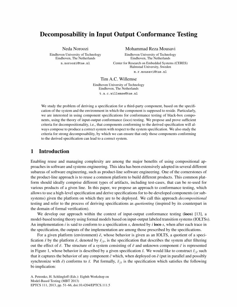
A. Petrenko, H. Schlingloff (Eds.): Eighth Workshop onModel-Based Testing (MBT 2013)EPTCS 111, 2013, pp. 51–66, doi:10.4204/EPTCS.111.5
Decomposability in Input Output Conformance Testing
Neda NorooziEindhoven University of Technology
Eindhoven, The [email protected]
Mohammad Reza MousaviEindhoven University of Technology
Eindhoven, The NetherlandsCenter for Research on Embedded Systems (CERES)
Halmstad University, [email protected]
Tim A.C. WillemseEindhoven University of Technology
Eindhoven, The [email protected]
We study the problem of deriving a specification for a third-party component, based on the specifi-cation of the system and the environment in which the component is supposed to reside. Particularly,we are interested in using component specifications for conformance testing of black-box compo-nents, using the theory of input-output conformance (ioco) testing. We propose and prove sufficientcriteria for decompositionality, i.e., that components conforming to the derived specification will al-ways compose to produce a correct system with respect to the system specification. We also study thecriteria for strong decomposability, by which we can ensure that only those components conformingto the derived specification can lead to a correct system.
1 Introduction
Enabling reuse and managing complexity are among the major benefits of using compositional ap-proaches in software and systems engineering. This idea has been extensively adopted in several differentsubareas of software engineering, such as product-line software engineering. One of the cornerstones ofthe product-line approach is to reuse a common platform to build different products. This common plat-form should ideally comprise different types of artifacts, including test-cases, that can be re-used forvarious products of a given line. In this paper, we propose an approach to conformance testing, whichallows to use a high-level specification and derive specifications for to-be-developed components (or sub-systems) given the platform on which they are to be deployed. We call this approach decompositionaltesting and refer to the process of deriving specifications as quotienting (inspired by its counterpart inthe domain of formal verification).
We develop our approach within the context of input-output conformance testing (ioco) [13], amodel-based testing theory using formal models based on input-output labeled transition systems (IOLTSs).An implementation i is said to conform to a specification s, denoted by i ioco s, when after each trace inthe specification, the outputs of the implementation are among those prescribed by the specifications.
For a given platform (environment) e, whose behavior is given as an IOLTS, a quotient of a speci-fication s by the platform e, denoted by s/e, is the specification that describes the system after filteringout the effect of e. The structure of a system consisting of e and unknown component c is representedin Figure 1, whose behavior is described by a given specification s. We would like to construct s/e suchthat it captures the behavior of any component c which, when deployed on e (put in parallel and possiblysynchronize with e) conforms to s. Put formally, s/e is the specification which satisfies the followingbi-implication:

52 Decomposability in IOCO
∀c, e. c ioco s/e ⇔ c||e ioco s
The criteria for the implication from left to right, which is essential for our approach, are called de-composability. The criteria for the implication from right to left guarantee that quotienting producesthe precise specification for the component and is called strong decomposability. We study both criteriain the remainder of this paper. Moreover, we show that strong decomposability can be combined withon-the-fly testing, thereby avoiding constructing the witness to the decomposability explicitly upfront.
platform e component cU ′e
I′eUv
Iv
U ′c
I′c
Figure 1: Strucure of a system composed of platform e and component c whose behavior is defined bya given specification s. The language of platform e comprises (I′e∪Uv)∪ (U ′e∪ Iv). Similarly, (I′c∪ Iv)∪(U ′c∪Uv) is the language of component c. The platform e and component c interface via Iv and Uv whichare hidden from the viewpoint of an external observer.
Related Work. The study of compositional and modular verification for various temporal and modallogics has attracted considerable attention and several compositional verification techniques have beenproposed for such logics; see, e.g., [2, 7, 10, 6]. Decompositional reasoning aims at automatically decom-posing the global property to be model checked into local properties of (possibly unknown) components,a technique that is often called quotienting. The notion of quotient introduced in the present paper isinspired by its corresponding notion in the area of (de)compositional model-checking, and is substan-tially adapted to the setting for input-output conformance testing, e.g., by catering for the distinctionbetween input and output actions and taking care of (relative) quiescence of components. In the area ofmodel-based testing, we are aware of a few studies dedicated to the issue of (de)composition [3, 5, 14],of which we give an overview below.
In [3] the compositionality of the ioco-based testing theory is investigated. Assuming that implemen-tations of components conform to their specifications, the authors investigate whether the composition ofthese implementations still conforms to the composition of the specifications. They show that this is notnecessarily the case and they establish conditions under which ioco is a compositional testing relation.
In [5], Frantzen and Tretmans study when successful integration of components by composing themin certain ways can be achieved. Successful integration is determined by two conditions: the integratedsystem correctly provides services, and interaction with other components is proper. For the former,a specification of the provided services of the component is assumed. Based on the ioco-relation, theauthors introduce a new implementation relation called eco, which allows for checking whether a com-ponent conforms to its specification as well as whether it uses other components correctly. In addition,they also propose a bottom-up strategy for building an integrated systems.
Another problem closely related to the problem we consider in this paper is testing in context, alsoknown as embedded testing [14]. In this setting, the system under test comprises a component c which isembedded in a context u. Component c is isolated from the environment and all its interactions proceedthrough u (which is assumed to be correctly implemented). The implementation i and specification s ofthe system composed of u and c, are assumed to be available. The problem of testing in context thenentails generating a test suite that allows for detecting incorrect implementations i of component c.
Noroozi, Mousavi & Willemse 53
Although testing in context and decomposability share many characteristics, there are key differencesbetween the two. We do not restrict ourselves to embedded components, nor do we assume the platformsto be fault-free. Contrary to the testing in context approach, decomposing a monolithic specification isthe primary challenge in our work; testing in context already assumes the specification is the result ofa composition of two specifications. Moreover, in testing in context, the component c is tested throughcontext u whereas our approach allows for testing the component directly through its deduced specifi-cation. As a result, we do not require that the context is always available while testing the component,which is particularly important in case the platform is a costly resource.
For similar reasons, asynchronous testing [11, 8, 15], which can be considered as some form ofembedded testing, is different from the work we present in this paper.
Structure. We give a cursory overview of ioco-based formal testing in Section 2. The notions of de-composability and strong decomposability are formalized in Section 3. We present sufficient conditionsfor determining whether a given specification is decomposable in Section 4 and whether it is stronglydecomposable in Section 5. We conclude in Section 6. Additional examples and results, together withall proofs for the lemmata and theorems can be found in [9].
2 Preliminaries
Conformance testing is about checking that the observable behavior of the system under test is includedin the prescribed behavior of the specification. In order to formally reason about conformance testing, weneed a model for reasoning about the behaviors described by a specification, and assume that we havea formal model representing the behaviors of our implementations, so that we can reason about theirconformance mathematically.
In this paper, we use variants of the well-known Labeled Transition Systems as a behavioral modelfor both the specification and the system under test. The Labeled Transition System model assumes thatsystems can be represented using a set of states and transitions, labeled with events or actions, betweensuch states. A tester can observe the events leading to new states, but she cannot observe the states. Weassume the presence of a special action τ , which we assume is unobservable to the tester.
Definition 1 (IOLTS) An input-output labeled transition system (IOLTS) is a tuple 〈S, I,U,→, s〉, whereS is a set of states, I and U are disjoint sets of observable inputs and outputs, respectively,→⊆ S× (I∪U ∪{τ})×S is the transition relation (we assume τ /∈ I∪U), and s ∈ S is the initial state. The class ofIOLTSs ranging over inputs I and outputs U is denoted IOLTS(I,U).
Throughout this section, we assume an arbitrary, fixed IOLTS 〈S, I,U,→, s〉, and we refer to thisIOLTS by referring to its initial state s. We write L for the set I∪U . Let s,s′ ∈ S and x ∈ L∪{τ}. In linewith common practice, we write s x−→ s′ rather than (s,x,s′) ∈→. Furthermore, we write s x−→ whenevers x−→ s′ for some s′ ∈ S, and s 6 x−→ when not s x−→. A word is a sequence over the input and output symbols.The set of all words over L is denoted L∗, and ε is the empty word. For words σ ,ρ ∈ L∗, we denote theconcatenation of σ and ρ by σρ . The transition relation is generalized to a relation over words by thefollowing deduction rules:
s ε=⇒ s
s σ=⇒ s′′ s′′ x−→ s′ x 6= τ
s σx==⇒ s′
s σ=⇒ s′′ s′′ τ−→ s′
s σ=⇒ s′

54 Decomposability in IOCO
We adopt the notational conventions we introduced for → for =⇒. A state in the IOLTS s is said todiverge if it is the source of an infinite sequence of τ-labeled transitions. The IOLTS s is divergent if oneof its reachable states diverges. Throughout this paper, we confine ourselves to non-divergent IOLTSs.
Definition 2 Let s′ ∈ S and S′ ⊆ S. The set of traces, enabled actions and weakly enabled actions for sand S′ are defined as follows:
• traces(s) = {σ ∈ L∗ | s σ=⇒}, and traces(S′) =
⋃s′∈S′
traces(s′).
• init(s) = {x ∈ L∪{τ} | s x−→}, and init(S′) =⋃
s′∈S′init(s′).
• Sinit(s) = {x ∈ L | s x=⇒}, and Sinit(S′) =
⋃s′∈S′
Sinit(s′).
Quiescence and Suspension Traces. Testers often not only have the power to observe events producedby an implementation, they can also observe the absence of events, or quiescence [13]. A state s ∈ S issaid to be quiescent if it does not produce outputs and it is stable. That is, it cannot, through internalcomputations, evolve to a state that is capable of producing outputs. Formally, state s is quiescent,denoted δ (s), whenever init(s)⊆ I. In order to formally reason about the observations of inputs, outputsand quiescence, we introduce the set of suspension traces. To this end, we first generalize the transitionrelation over words to a transition relation over suspension words. Let Lδ denote the set L∪{δ}.
s σ=⇒ s′
s σ=⇒δ s′
δ (s)
s δ=⇒δ s
s σ=⇒δ s′′ s′′
ρ=⇒δ s′
sσρ==⇒δ s′
The following definition formalizes the set of suspension traces.
Definition 3 Let s ∈ S and S′ ⊆ S. The set of suspension traces for s, denoted Straces(s) is defined asthe set {σ ∈ L∗δ | s
σ=⇒δ}; we set Straces(S′) =
⋃s′∈S′
Straces(s′).
Input-Output Conformance Testing with Quiescence. Tretmans’ ioco testing theory [13] formalizesblack box conformance of implementations. It assumes that the behavior of implementations can alwaysbe described adequately using a class of IOLTSs, called input output transition systems; this assumptionis the so-called testing hypothesis. Input output transition systems are essentially plain IOLTSs with theadditional assumption that inputs can always be accepted.
Definition 4 (IOTS) Let 〈S, I,U,→, s〉 be an IOLTS. A state s ∈ S is input-enabled iff I ⊆ Sinit(s); theIOLTS s is an input output transition system (IOTS) iff every state s ∈ S is input-enabled. The class ofinput output transition systems ranging over inputs I and outputs U is denoted IOTS(I,U).
While the ioco testing theory assumes input-enabled implementations, it does not impose this require-ment on specifications. This facilitates testing using partial specifications, i.e., specifications that areunder-specified. We first introduce the main concepts that are used to define the family of conformancerelations of the ioco testing theory.
Definition 5 Let 〈S, I,U,→, s〉 be an IOLTS. Let s ∈ S, S′ ⊆ S and let σ ∈ L∗δ .
Noroozi, Mousavi & Willemse 55
• s after σ = {s′ ∈ S | s σ=⇒δ s′}, and S′ after σ =
⋃s′∈S′
s′ after σ .
• out(s) = {x ∈ Lδ \ I | s x=⇒δ}, and out(S′) =
⋃s′∈S′
out(s′).
The family of conformance relations for ioco are then defined as follows, see also [13].
Definition 6 (ioco) Let 〈R, I,U,→, r〉 be an IOTS representing a realization of a system, and let IOLTS〈S, I,U,→, s〉 be a specification. Let F ⊆ L∗δ . We say that r is input output conform with specification s,denoted r iocoF s, iff
∀σ ∈ F : out(r after σ)⊆ out(s after σ)
The iocoF conformance relation can be specialized by choosing an appropriate set F . For instance, ina setting with F = Straces(s), we obtain the ioco relation originally defined by Tretmans in [12]. Thelatter conformance relation is known to admit a sound and complete test case generation algorithm,see, e.g., [12, 13]. Soundness means, intuitively, that the algorithm will never generate a test case that,when executed on an implementation, leads to a fail verdict if the test runs are in accordance with thespecification. Completeness is more esoteric: if the implementation has a behavior that is not in line withthe specification, then there is a test case that, in theory, has the capacity to detect that non-conformance.
Suspension automata. The original test case generation algorithm by Tretmans for the ioco relationrelied on an automaton derived from an IOLTS specification. This automaton, called a suspension au-tomaton, shares many of the characteristics of an IOLTS, except that the observations of quiescence areencoded explicitly as outputs: δ is treated as an ordinary action label which can appear on a transition.In addition, Tretmans assumes these suspension automata to be deterministic: any word that could beproduced by an automaton leads to exactly one state in the automaton.
Definition 7 (Suspension automaton) A suspension automaton(SA) is a deterministic IOLT S 〈S, I,U ∪{δ},→, s〉; that is, for all s ∈ S and all σ ∈ L∗, we have |s after σ | ≤ 1.
Note that determinism implies the absence of τ transitions. In [12], a transformation from ordinaryIOLTSs to suspension automata is presented; the transformation ensures that trace-based testing usingthe resulting suspension automaton is exactly as powerful as ioco-based testing using the original IOLTS.
The transformation is essentially based on the subset construction for determinizing automata. Givenan IOLTS, the transformation ∆ defined below converts any IOLTS into an SA.
Definition 8 Let 〈S, I,U,→, s〉 ∈ IOLTS(I,U). The SA ∆(s) = 〈Q, I,U ∪{δ},→, q〉 is defined as:• Q = P(S)\{ /0}.• q = s after ε .
• →⊆ Q×Lδ ×Q is the least relation satisfying:x ∈ L q ∈ Q
q x−→ {s′ ∈ S | ∃s ∈ q• s x=⇒ s′}
q ∈ Q
q δ−→ {s ∈ q | δ (s)}
Example 1 Consider the IOLTS s depicted in Figure 2 on page 57. The IOLTS s is a specification of amalfunctioning vending machine which sells tea for one euro coin (c). After receiving money, it eitherdelivers tea (t), refunds the money (r) or does nothing. Its suspension automaton ∆(s), with initial stateq, is depicted next to it. Note that the suspension traces of s and the traces of suspension automaton ∆(s)are identical.

56 Decomposability in IOCO
In general, a suspension automaton may not represent an actual IOLTS; for instance, in an arbitrarysuspension automaton, it is allowed to observe quiescence, followed by a proper output. This cannothappen in an IOLTS. In [16], the set of suspension automata is characterized for which a transformationto an IOLTS is possible. Such suspension automata are called valid. Proposition 1 of [16] states that forany IOLTS s, the suspension automaton ∆(s) is valid. Conversely, Theorem 2 of [16] states that any validsuspension automaton has the same testing power (with respect to ioco) as some IOLTS. This essentiallymeans that the class of valid suspension automata can be used safely for testing purposes.
Parallel Composition. A software or hardware system is usually composed of subunits and modulesthat work in an orchestrated fashion to achieve the desired overall behavior of the software or hardwaresystem. In our setting, we can formalize such compositions using a special operator || on IOLTSs: twoIOLTSs can interact by connecting the outputs sent by one IOLTS to the inputs of the other IOLTS. Weassume that such inputs and outputs are taken from a shared alphabet of actions. For the non-commonactions the behavior of both IOLTSs is interleaved.
Definition 9 (parallel composition) Let 〈S1, I1,U1,→1, s1〉 and 〈S2, I2,U2,→2, s2〉 be two IOLTSs withdisjoint sets of input labels I1 and I2, and disjoint sets of output labels U1 and U2. The parallel composi-tion of s1 and s2, denoted s1||s2 is the IOLTS 〈Q, I,U,→, s1||s2〉, where:
• Q = {s1||s2 | s1 ∈ S1,s2 ∈ S2}.• I = (I1∪ I2)\ (U1∪U2) and U =U1∪U2.
• →⊆ Q× (L∪{τ})×Q is the least relation satisfying:
s1x−→1 s′1 x 6∈ L2
s1||s2x−→ s′1||s2
s2x−→2 s′2 x 6∈ L1
s1||s2x−→ s1||s′2
s1x−→1 s′1 s2
x−→2 s′2 x 6= τ
s1||s2x−→ s′1||s′2
The interaction between components is typically intended to be unobservable by a tester. This is notenforced by the parallel composition, but can be specified by combining parallel composition with ahiding operator, which is formalized below.
Definition 10 (hiding) Let 〈S, I,U,→, s〉 be an IOLTS, and let V ⊆U. The IOLTS resulting from hidingevents from the set V , denoted by hide[V ] ins is the IOLTS 〈S, I,U \V,→′, s〉, where→′ is defined as theleast relation satisfying:
s x−→ s′ x 6∈V
hide[V ] ins x−→′ hide[V ] ins′s x−→ s′ x ∈V
hide[V ] ins τ−→′ hide[V ] ins′
Note that the hiding operator may turn non-divergent IOLTSs into divergent IOLTSs. As divergence isexcluded from the ioco testing theory, we must assume such divergences are not induced by composingtwo implementations in parallel and hiding all successful communications. Since implementations areassumed to be input enabled, this can only be ensured whenever components that are put in parallel neverproduce infinite, uninterrupted runs of outputs over their alphabet of shared output actions. Implemen-tations adhering to these constraints are referred to as shared output bounded implementations. Fromhereon, we assume that all the implementions considered are shared output bounded.

Noroozi, Mousavi & Willemse 57
3 Decomposibility
Software can be constructed by decomposing a specification of the software in specifications of smallercomplexity. Reuse of readily available and well-understood platforms or environments can steer such adecomposition. Given the prevalence of such platforms, the software engineering and associated testingproblem thus shifts to finding a proper specification of the system from which the platform behavior hasbeen factored out. Whether this is possible, however, depends on the specification; if so, we say that aspecification is decomposable.
The decomposability problem requires known action alphabets for both the specification and theplatform. Hence, we first fix these alphabets and illustrate how these are related. Hereafter, Ls denotesthe action alphabet of the specification s and Le denotes the action alphabet of the platform e. The actionsof Le not exposed to s are contained in action alphabet Lv, i.e., we have Lv = Le \Ls. The action alphabetof the quotient will be denoted by L, i.e. L = (Ls \Le)∪Lv. The relation between the above alphabets isillustrated in Figure 1 in the introduction.
Definition 11 (Decomposability) Let s ∈ IOLTS(Is,Us) be a specification, and let e ∈ IOTS(Ie,Ue) bean implementation. Let Lv = Iv ∪Uv be a set of actions of e not part of s. Specification s is said to bedecomposable for IOTS e iff there is some specification s′ ∈ IOLTS((Is \ Ie)∪ Iv,(Us \Ue)∪Uv) for whichboth:
• ∃c ∈ IOTS((Is \ Ie)∪ Iv,(Us \Ue)∪Uv) • c ioco s′, and
• ∀c ∈ IOTS((Ie \ Ie)∪ Iv,(Ue \Ue)∪Uv) • c ioco s′ =⇒ hide[Lv] in c||e ioco s
Decomposability of a specification s essentially ensures that a specification s′ for a subcomponent ex-ists that guarantees that every ioco-correct implementation of it is also guaranteed to work correctly incombination with the platform.
s
s1
c
r
τ
t
τ
(a) IOLTS s
q cδ
r
δt
δδ
(b) SA ∆(s)
eerror c order
τ
τ
(c) IOTS e
rerror c order
τ
τ
error
r
τ
(d) IOTS r
morder
errort
(e) IOLTS m
porder
errort
error
τ
(f) IOLTS p
corder
errortorder
order
error
order
(g) IOTS c
Figure 2: A specification of a vending machine (s), two behavioral models of an implemented moneycomponent (e and r) and two specifications for a drink component (m and p) with the behavioral modelof an implementation of the drink component (c).
Example 2 Consider IOLTSs depicted in Figure 2. The IOTS e 2(c) presents the behavioral model of anenvironment which after receiving a coin (c) either orders drink (order) or does nothing. Upon receivingan error signal (error), never refunds the money (r). Component e interacts with another component

58 Decomposability in IOCO
through actions ‘order’ and ‘error’; together, the components implement a vending machine for whichIOLTS s 2(a) is the specification. The IOLTS m 2(e) is a specification of a drink component whichdelivers tea after receiving a drink order. If it encounters a problem in delivering the drink, it signalsan error. Specification m guarantees that the combination of component e with any drink componentimplementation conforming to m, also conforms to s.
It may, however, be the case that an implementation, in combination with a given platform, perfectlyadheres to the overall specification s, and, yet fails to pass the conformance test for s′. As a consequence,non-conformance of an implementation to s′ may not by itself be a reason to reject the implementation.
Example 3 Consider IOLTSs in Figure 2. The IOLTS m 2(e) is a witness for decomposability of IOLTSs2(a) for platform e2(c). Thus, any compound system built of IOTS e and a component conforming to mis guaranteed to be in conformance with IOLTS s. Now, consider IOTS c 2(g) which incorrectly imple-ments the functionality specified in IOLTS m 2(e), as it sends ‘error’ twice. Observe that, nevertheless,hide[{error,order}] in c||e still conforms to s.
It is often desirable to consider specifications s′ for which one only has to check whether an imple-mentation c adheres to s′, i.e., specifications for which it is guaranteed that a failure of an implementationc to comply to s′ also guarantees that the combination c||e will violate the original specification s. Wecan obtain this by considering a stronger notion of decomposability.
Definition 12 (Strong Decomposability) Let s∈ IOLTS(I,U) be a specification, and let e∈ IOTS(Ie,Ue)be an implementation. Let Lv = Iv∪Uv be a set of actions of e not part of s. Specification s is said to bestrongly decomposable for IOTS e iff there is some specification s′ ∈ IOLTS((Is \ Ie)∪ Iv,(Us \Ue)∪Uv)for which both:
• ∃c ∈ IOTS((Is \ Ie)∪ Iv,(Us \Ue)∪Uv) • c ioco s′, and
• ∀c ∈ IOTS((Is \ Ie)∪ Iv,(Us \Ue)∪Uv) • c ioco s′⇐⇒ hide[Lv] in c||e ioco s
Example 4 Consider the IOLTSs p and e in Figure 2; specification p is such that the combination ofcomponent e with any shared output bounded component that does not conform to p, fails to comply to s.
4 Sufficient Conditions for Decomposibility
Checking whether a given specification is decomposable is a difficult problem. However, knowing that aspecification is decomposable in itself hardly helps a design engineer. Apart from the question whethera specification is decomposable, one is typically interested in a witness for the decomposed specifica-tion, or quotient. Our approach to the decomposability problem is therefore constructive: we define aquotient and we identify several conditions that ensure that the quotient we define is a witness for thedecomposability of a given specification.
One of the problems that may prevent a specification from being decomposable for a given platforme is that the latter may exhibit some behavior which unavoidably violates the specification s. We shalltherefore only consider platforms for which such violations are not present. We formalize this by check-ing whether the behavior of e is included in the behavior of s; that is, we give conditions that ensurethat e in itself cannot violate the given specification s. Moreover, we assume that the input-enabledspecification of e is available.

Noroozi, Mousavi & Willemse 59
Assuming that the behavior of e is included in the behavior of the given specification s, we then pro-pose a quotient s′ of s for e and prove sufficient conditions that guarantee that s is indeed decomposableand s′ is a witness to that.
4.1 Inclusion relation
We say that the behavior of a given platform e is included in a specification s if the outputs allowed bys subsume all outputs that can be produced by e. For this, we need to take possible communicationsbetween e and the to-be-derived quotient over the action alphabet Lv into account. Another issue is thatwe are dealing with two components, each of which may be quiescent. If component e is quiescent, itsquiescence may be masked by outputs from the component with which it is supposed to interact. Wemust therefore consider a refined notion of quiescence. We say state s in specification s is relativelyquiescent with respect to alphabet Le, denoted by δe(s), if s produces no output of Le, i.e. out(s)∩Le = /0.
Analogous to δ , the suspension traces of s can be enriched by adding the rule s δe=⇒δ s for δe(s) to beable to formally reason about the possibility of being relatively quiescent with respect to Le. We writeStracese(s) to denote this enriched set of suspension traces of s.
Since the suspension traces of s and e differ as a result of different alphabets, we introduce a projec-tion operator which allows us to map the suspension traces of s to suspension traces of e. The operator↓Le
is defined as (xσ)↓Le= xσ↓Le
if x ∈ Le; (xσ)↓Le= δ (σ↓Le
), if x ∈ {δ ,δe}; otherwise, (xσ)↓Le= σ↓Le
.
Definition 13 Let IOTS 〈Se, Ie,Ue,→, e〉 be an implementation. Let IOLTS 〈Ss, Is,Us,→, s〉 be a specifi-cation. We say the behavior of e is included in s, denoted by e incl s iff
∀σ ∈ Stracese(s) : out(hide[Lv] in e after σ↓Le)⊆ out(s after σ)
Example 5 Consider the IOLTSs in Figure 2. We have e incl s. Consider the IOLTS r which has thesame functionality with IOLTS e except that upon receiving an error signal (error), it may or may notrefund the money (r). The behavior of r is not included in s, because of observing the output r in r afterexecuting (ct)↓Le
while s after execution of ct reaches to a quiescent state.
4.2 Quotienting
We next focus on deriving a quotient of the specification s, factoring out the behavior of the platform e.A major source of complexity in defining such a quotient is the possible non-determinism that may bepresent in s and e. We largely avert this complexity by utilizing the suspension automata underlying sand e.
Another source of complexity is the fact that we must reason about the states of two systems runningin parallel; such a system synchronizes on shared actions and interleaves on non-shared actions. Wetame this conceptual complexity by formalizing an executes operator which, when executing a sharedor non-shared action, keeps track of the set of reachable states for the (suspension automata) of s and e.Formally, the executes operator is defined as follows.
Definition 14 Let 〈Qs, Is,Us ∪{δ},→s, qs〉 be a suspension automaton underlying specification IOLTSs, and let 〈Qe, Ie,U ∪{δ},→e, qe〉 be a suspension automaton underlying platform IOLTS e. Let q ∈P(Qs×Qe) be a non-empty collection of sets and let x ∈ Ls \ (Le \Lv).
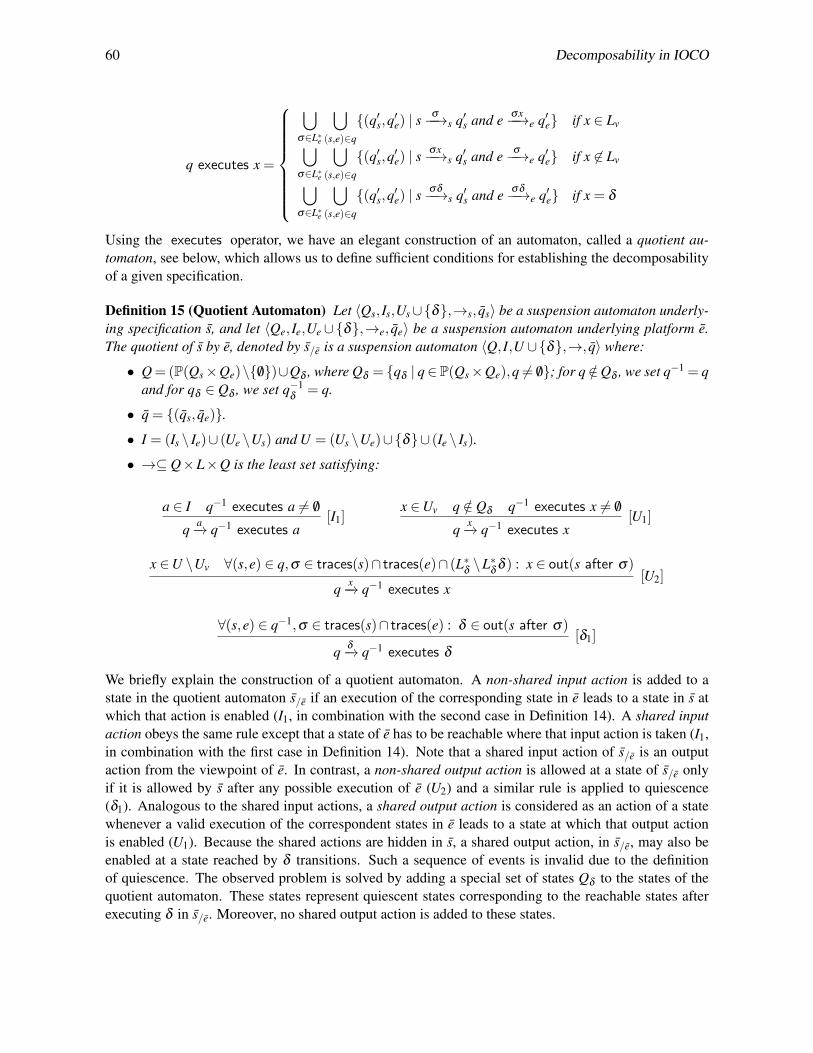
60 Decomposability in IOCO
q executes x =
⋃
σ∈L∗e
⋃
(s,e)∈q
{(q′s,q′e) | sσ−−→s q′s and e σx−−→e q′e} if x ∈ Lv
⋃
σ∈L∗e
⋃
(s,e)∈q
{(q′s,q′e) | sσx−−→s q′s and e σ−−→e q′e} if x 6∈ Lv
⋃
σ∈L∗e
⋃
(s,e)∈q
{(q′s,q′e) | sσδ−−→s q′s and e σδ−−→e q′e} if x = δ
Using the executes operator, we have an elegant construction of an automaton, called a quotient au-tomaton, see below, which allows us to define sufficient conditions for establishing the decomposabilityof a given specification.
Definition 15 (Quotient Automaton) Let 〈Qs, Is,Us∪{δ},→s, qs〉 be a suspension automaton underly-ing specification s, and let 〈Qe, Ie,Ue ∪{δ},→e, qe〉 be a suspension automaton underlying platform e.The quotient of s by e, denoted by s/e is a suspension automaton 〈Q, I,U ∪{δ},→, q〉 where:
• Q= (P(Qs×Qe)\{ /0})∪Qδ , where Qδ = {qδ | q∈P(Qs×Qe),q 6= /0}; for q /∈Qδ , we set q−1 = qand for qδ ∈ Qδ , we set q−1
δ = q.
• q = {(qs, qe)}.• I = (Is \ Ie)∪ (Ue \Us) and U = (Us \Ue)∪{δ}∪ (Ie \ Is).
• →⊆ Q×L×Q is the least set satisfying:
a ∈ I q−1 executes a 6= /0
q a−→ q−1 executes a[I1]
x ∈Uv q /∈ Qδ q−1 executes x 6= /0
q x−→ q−1 executes x[U1]
x ∈U \Uv ∀(s,e) ∈ q,σ ∈ traces(s)∩ traces(e)∩ (L∗δ \L∗δ δ ) : x ∈ out(s after σ)
q x−→ q−1 executes x[U2]
∀(s,e) ∈ q−1,σ ∈ traces(s)∩ traces(e) : δ ∈ out(s after σ)
q δ−→ q−1 executes δ[δ1]
We briefly explain the construction of a quotient automaton. A non-shared input action is added to astate in the quotient automaton s/e if an execution of the corresponding state in e leads to a state in s atwhich that action is enabled (I1, in combination with the second case in Definition 14). A shared inputaction obeys the same rule except that a state of e has to be reachable where that input action is taken (I1,in combination with the first case in Definition 14). Note that a shared input action of s/e is an outputaction from the viewpoint of e. In contrast, a non-shared output action is allowed at a state of s/e onlyif it is allowed by s after any possible execution of e (U2) and a similar rule is applied to quiescence(δ1). Analogous to the shared input actions, a shared output action is considered as an action of a statewhenever a valid execution of the correspondent states in e leads to a state at which that output actionis enabled (U1). Because the shared actions are hidden in s, a shared output action, in s/e, may also beenabled at a state reached by δ transitions. Such a sequence of events is invalid due to the definitionof quiescence. The observed problem is solved by adding a special set of states Qδ to the states of thequotient automaton. These states represent quiescent states corresponding to the reachable states afterexecuting δ in s/e. Moreover, no shared output action is added to these states.

Noroozi, Mousavi & Willemse 61
r
1
1
order
error
δt
error
orderδδerror
δδorder
error
error
δ
δ order
error
(a) SA r
iordererror
t
errorδerror
δerror
error
δ
error order error
δ
δ
(b) SA i
Figure 3: Two quotient automata derived using Definition 15
The quotient automaton derived from specification s and platform e is a suspension automaton: itis deterministic and it has explicit δ labels. Yet, the quotient automata we derive are not necessarilyvalid suspension automata. (As we recalled in Section 2, only valid suspension automata have the sametesting power as ordinary IOLTSs.) We furthermore observe that there some quotient automata that arevalid suspension automata but nevertheless only admit non-shared output bounded implementations asimplementations that conform to the quotient. As observed earlier, such implementations unavoidablygive rise to divergent systems when composed in parallel with the platform.
Example 6 Consider SAs depicted in Figure 3, IOLTSs s and e in Figure 2 and IOLTS l derived byremoving the internal transition from state s1 to the initial state in s. SA r is the quotient of s by e.Likewise, SA i is the quotient of l by e. Suspension automata r and i are valid SA regarding the definitionof validity of suspension automata presented in [16] . Assume an arbitrary shared output bounded IOTSc whose length of the longest sequence on the shared output is n, i.e. out(c after σ)⊆ {tea,δ} for σ ={error}n. Clearly, c���ioco i, because out(i after σ) = {error}. However, for any n≥ 0, there is always ashared output bounded IOTS that conforms to r.
In view of the above, we say that a quotient automaton is valid if it is a valid suspension automaton andstrongly non-blocking.
Definition 16 Let s/e be a quotient automaton derived from a specification s and an environment e. Wesay that s/e is valid iff both:
• s/e is a valid suspension automaton, and
• s/e is strongly non-blocking, i.e. ∀q ∈ s/e •out(q)∩((U \Uv)∪{δ}) 6= /0.
Strongly non-blocking ensures that the quotient automaton always admits a shared output bounded im-plementation that conforms to it. Furthermore, valid quotient automata are, by definition, also validsuspension automata. Since every valid suspension automaton underlies at least one IOLTS, we there-fore have established a sufficient condition for the decomposability of a specification.
Theorem 1 Let s ∈ IOLTS(Is,Us) be a specification and let e ∈ IOTS(Ie,Ue) be an environment. Then sis decomposable for e if s/e is a valid quotient automaton and e incl s.
Note that the IOLTS underlying the quotient automaton is a witness to the decomposability of the spec-ification; we thus not only have a sufficient condition for the decomposability of a specification but alsoa witness for the decomposition.

62 Decomposability in IOCO
POS
ATM
E-Payment
Core Banking
Inter-bank Netw.
EFT
Switch
(IUT)
(a) Schematic view
s
1 3 4
5 7
p rq
rev rq
rev rq
p rs
τ
rev rqp rq
rev rqδ
δ
(b) SA s
e 1
2
3
p rqp rs
p rs
tp rs, δ
p rs, δ
(c) SA e
0
1
2
3
4
5
6 7
t
rev rq
rev rq
t
rev rq
δ
rev rq
t
rev rq
δ
δrev rq
δ
(d) s/e
Figure 4: A schematic view of the EFT Switch, a suspension automata of simplified behavioral modelsof the EFT switch s and an implementation of the financial component e, and the quotient of s w.r.t. e
4.3 Example
To illustrate the notions introduced so far, we treat a simplified model of an Electronic Funds Transfer(EFT) switch, which we have studied and tested using ioco-based techniques [1]. A schematic view ofthis example is depicted in Figure 4(a). An EFT switch provides a communication mechanism amongdifferent components of a card-based financial system. On one side of the EFT switch, there are compo-nents, with which the end-user deals, such as Automated Teller Machines (ATMs), Point-of-Sale (POS)devices and e-Payment applications. On the other side, there are banking systems and the inter-banknetwork connecting the switches of different financial institutions.
The various involving parties in every transaction performed by an EFT switch in conjunction withthe variety of financial transactions complicate the behavioral model of the EFT switch. Similar to anyother complex software system, the EFT switch comprises many different components, some of whichcan be run individually.
A part of the simplified communication model of the EFT switch with a banking system in thepurchase scenario is depicted in Figure 4(b). The scenario starts by receiving a purchase request from aPOS; this initial part of the scenario is removed from the model, for the sake of brevity. Subsequently, theEFT switch sends a purchase request (p rq) to the banking system. The EFT switch will reverse (rev rq)the sent purchase request if the corresponding response (p rs) is not received within a certain amount oftime (e.g, an internal time-out occurs, denoted by τ). Due to possible delays in the network layer of theEFT switch, an external observer (tester) may observe the reverse request of a purchase even before thepurchase request which is pictured in Fig 4(b).
The EFT switch is further implemented in terms of two components, namely, the financial componentand the reversal component. A simplified behavioral model of the financial component is given in Figure4(c). Comparing the two languages of s and e, t action (representing time-out) is considered as an internal

Noroozi, Mousavi & Willemse 63
interface between e and a to-be-developed implementation of the reversal component. Observe thatfor every sequence σ in {p rq(δe|rev rq)∗, p rq(δe|rev rq)∗rev rq(δ |δe)
∗, p rq p rs(δe|rev rq)∗(δ |δe)∗,
(δe|rev rq)∗,(δe|rev rq)∗rev rq(rev rq|p rq)∗(δ |δe)∗}, it holds that out(hide[t] in e after σ↓Le
) ⊆out(s after σ); thus, the behavior of e is included in s. We next instigate investigate decomposability ofs with e, by constructing the quotient s/e. Note that t is the only shared action which is an input actionfrom the view point of s/e. The resulting quotient automaton, obtained by applying Definition 15 to sand e is depicted in Figure 4(d). We illustrate some steps in its derivation. The initial state of the quotientautomaton is defined as the {(s, e)}. Below, we illustrate which of the rules of Definition 15 are possiblefrom this initial state; doing so repeatedly for all reached states will ultimately produce the reachablestates of the quotient automaton.
1. We check the possibility of adding input transitions to the initial state, i.e. q0 = {(s, e)}. Followingq0 executes t = {(s1,e2)} and deduction rule I1 in Definition 15, the transition q0
t−→ q1 is addedto the transition relation of s/e where q1 = {(s1,e2)} (state 1 in Figure 4(d)).
2. We check the possibility of adding output transitions to q0 = {(s, e)}. We observe that rev rq ∈out(s after σ) for every σ ∈ {ε, p rq, p rq p rs}. Regarding deduction rule U2, the transitionq0
rev rq−−−→ q2 is added to the transition relation of s/e where q2 = {(s5, e),(s2,e1),(s2,e3)} (state 2in Figure 4(d)).
3. Following deduction rule δ1 and δ 6∈ out(s after ε), δ -labeled transition is not added to q0.
The constructed quotient automaton s/e is valid: it is both a valid suspension automaton and stronglynon-blocking. As a result, s is decomposable with respect to e and s/e is a witness to that.
5 Strong Decomposibility
It is a natural question whether the quotient automaton that we defined in the previous section, along withthe sufficient conditions for decomposability of a specification provide sufficient conditions for strongdecomposability. The proof of Theorem 1 gives some clues to the contrary. A main problem is in thenotion of quiescence, and, in particular in the notion of relative quiescence, which is unobservable in thestandard ioco theory. More specifically, the platform e may mask the (unwanted) lack of outputs of thequotient automaton.
A natural solution to this is to consider a subclass of implementations called internal choice IOTSs,studied in [8, 15]: such implementations only accept inputs when reaching a quiescent state. The propo-sition below states that strong decomposability can be achieved under these conditions.
Theorem 2 Let s ∈ IOLTS(Is,Us) be a specification and let e ∈ IOTS(Ie,Ue) be an environment. If s isdecomposable and e is an internal choice IOTS then s is strongly decomposable and s/e is a witness tothis.
As a result of the above theorem, testing whether the composition of a component c and a platform econforms to specification s reduces to testing for the conformance of c to s/e. This can be done using thestandard ioco testing theory [13].
A problem may arise when trying this approach in practice. Namely, the amount of time and mem-ory needed for derivation of the ioco test suit increases exponentially in the number of transitions in thespecification due to the nondeterministic nature of the test-case generation algorithm. We avoid thesecomplexities by presenting an on-the-fly testing algorithm inspired by [4]. Algorithm 1 describes the
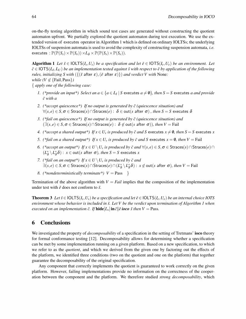
64 Decomposability in IOCO
on-the-fly testing algorithm in which sound test cases are generated without constructing the quotientautomaton upfront. We partially explored the quotient automaton during test execution. We use the ex-tended version of executes operator in Algorithm 1 which is defined on ordinary IOLTSs; the underlyingIOLTSs of suspension automata is used to avoid the complexity of constructing suspension automata, i.e.executes : P(P(Ss)×P(Se))×Lδ ×P(P(Ss)×P(Se)).
Algorithm 1 Let s ∈ IOLTS(Is,Us) be a specification and let e ∈ IOTS(Ie,Ue) be an environment. Letc ∈ IOTS(LI,LU) be an implementation tested against s with respect to e by application of the followingrules, initializing S with ({(s after ε),(e after ε)}) and verdict V with None:while (V 6∈ {Fail,Pass}){ apply one of the following case:
1. (*provide an input*) Select an a∈ {a∈ LI | S executes a 6= /0}, then S = S executes a and providec with a
2. (*accept quiescence*) If no output is generated by c (quiescence situation) and∀(s,e) ∈ S,σ ∈ Straces(s)∩Straces(e) : δ ∈ out(s after σ) , then S = S executes δ
3. (*fail on quiescence*) If no output is generated by c (quiescence situation) and(∃(s,e) ∈ S,σ ∈ Straces(s)∩Straces(e) : δ 6∈ out(s after σ)), then V = Fail
4. (*accept a shared output*) If x ∈Uv is produced by c and S executes x 6= /0, then S = S executes x
5. (*fail on a shared output*) If x ∈Uv is produced by c and S executes x = /0, then V = Fail
6. (*accept an output*) If x ∈U \Uv is produced by c and ∀(s,e) ∈ S,σ ∈ Straces(s)∩Straces(e)∩(L∗δ \L∗δ δ ) : x ∈ out(s after σ), then S = S executes x
7. (*fail on an output*) If x ∈U \Uv is produced by c and∃(s,e) ∈ S,σ ∈ Straces(s)∩Straces(e)∩ (L∗δ \L∗δ δ ) : x 6∈ out(s after σ), then V = Fail
8. (*nondeterministically terminate*) V = Pass }
Termination of the above algorithm with V = Fail implies that the composition of the implementationunder test with e does not conform to s.
Theorem 3 Let s∈ IOLTS(Is,Us) be a specification and let e∈ IOLTS(Ie,Ue) be an internal choice IOTSenvironment whose behavior is included in s. Let V be the verdict upon termination of Algorithm 1 whenexecuted on an implementation c. If hide[Lv] in c||e ioco s then V = Pass.
6 Conclusions
We investigated the property of decomposability of a specification in the setting of Tretmans’ ioco theoryfor formal conformance testing [12]. Decomposability allows for determining whether a specificationcan be met by some implementation running on a given platform. Based on a new specification, to whichwe refer to as the quotient, and which we derived from the given one by factoring out the effects ofthe platform, we identified three conditions (two on the quotient and one on the platform) that togetherguarantee the decomposability of the original specification.
Any component that correctly implements the quotient is guaranteed to work correctly on the givenplatform. However, failing implementations provide no information on the correctness of the cooper-ation between the component and the platform. We therefore studied strong decomposability, which
Noroozi, Mousavi & Willemse 65
further strengthens the decomposability problem to ensure that only those components that correctlyimplement the quotient are guaranteed to work correctly on the given platform, meeting the overall spec-ification. This ensures that testing a component against the quotient provides all information needed tojudge whether it will work correctly on the platform and meet the overall specification’s requirements.However, the complexity of computing the quotient is an exponential problem. We propose an on-the-flytest case derivation algorithm which does not compute the quotient explicitly. Components that fail sucha test case provably fail to work on the platform, meeting the overall specification, too.
Checking the inclusion relation of a platform may be expensive in practice. As for future work, wewould like to merge the two steps of checking the correctness of the platform and driving the quotient andinvestigate whether the constraints on the platform can be relaxed by ensuring that the derived quotientmasks some of the unwanted behavior of the platform.
References
[1] H. R. Asaadi, R. Khosravi, M. R. Mousavi & N. Noroozi (2011): Towards Model-Based Testing of ElectronicFunds Transfer Systems. In: FSEN, LNCS 7141, pp. 253–267. Available at http://dx.doi.org/10.1007/978-3-642-29320-7_17.
[2] S. Berezin, S. Campos & E.M. Clarke (1998): Compositional Reasoning in Model Checking. In: Compo-sitionality: The Significant Difference, LNCS 1536, Springer, pp. 81–102. Available at http://dx.doi.org/10.1007/3-540-49213-5_4.
[3] M. van der Bijl, A. Rensink & J. Tretmans (2003): Compositional Testing with ioco. In: FATES, LNCS 2931,Springer, pp. 86–100. Available at http://dx.doi.org/10.1007/978-3-540-24617-6_7.
[4] R.G. de Vries & J. Tretmans (2000): On-the-fly Conformance Testing using SPIN. STTT 2(4), pp. 382–393.Available at http://dx.doi.org/10.1007/s100090050044.
[5] L. Frantzen & J. Tretmans (2006): Model-Based Testing of Environmental Conformance of Compo-nents. In: FMCO, LNCS 4709, Springer, pp. 1–25. Available at http://dx.doi.org/10.1007/
978-3-540-74792-5_1.
[6] D. Giannakopoulou, C. S. Pasareanu & H. Barringer (2005): Component Verification with AutomaticallyGenerated Assumptions. Autom. Softw. Eng. 12(3), pp. 297–320. Available at http://dx.doi.org/10.1007/s10515-005-2641-y.
[7] O. Kupferman & M. Vardi (1998): Modular model checking. In: Compositionality: The Significant Differ-ence, LNCS 1536, Springer, pp. 81–102. Available at http://dx.doi.org/10.1007/3-540-49213-5_4.
[8] N. Noroozi, R. Khosravi, M.R. Mousavi & T. A. C. Willemse (2011): Synchronizing Asynchronous Con-formance Testing. In: SEFM, LNCS 7041, Springer, pp. 334–349. Available at http://dx.doi.org/10.1007/978-3-642-24690-6_23.
[9] N. Noroozi, M.R. Mousavi & T.A.C. Willemse (2013): Decomposability in Formal Conformance Testing.Technical Report CSR-13-02, TU/Eindhoven.
[10] C. S. Pasareanu, M. B. Dwyer & M. Huth (1999): Assume-Guarantee Model Checking of Software: AComparative Case Study. In: Theoretical and Practical Aspects of SPIN Model Checking, LNCS 1680,Springer, pp. 168–183. Available at http://dx.doi.org/10.1007/3-540-48234-2_14.
[11] A. Simao & A. Petrenko (2011): Generating asynchronous test cases from test purposes. Information &Software Technology 53(11), pp. 1252–1262. Available at http://dx.doi.org/10.1016/j.infsof.2011.06.006.
[12] J. Tretmans (1996): Test Generation with Inputs, Outputs and Repetitive Quiescence. Software - Conceptsand Tools 17(3), pp. 103–120.

66 Decomposability in IOCO
[13] J. Tretmans (2008): Model Based Testing with Labelled Transition Systems. In: Formal Methods and Testing,LNCS 4949, Springer, pp. 1–38. Available at http://dx.doi.org/10.1007/978-3-540-78917-8_1.
[14] T. Villa, N. Yevtushenko, R.K. Brayton, A. Mishchenko, A. Petrenko & A. Sangiovanni-Vincentelli (2012):The Unknown Component Problem, Theory and Applications. Springer, doi:10.1007/978-0-387-68759-9.
[15] M. Weiglhofer & F. Wotawa (2009): Asynchronous Input-Output Conformance Testing. In: COMPSAC,IEEE Computer Society, pp. 154–159. Available at http://dx.doi.org/10.1109/COMPSAC.2009.194.
[16] T. A. C. Willemse (2006): Heuristics for ioco -Based Test-Based Modelling. In: FMICS/PDMC, LNCS 4346,Springer, pp. 132–147. Available at http://dx.doi.org/10.1007/978-3-540-70952-7_9.

A. Petrenko, H. Schlingloff (Eds.): Eighth Workshop onModel-Based Testing (MBT 2013)EPTCS 111, 2013, pp. 67–81, doi:10.4204/EPTCS.111.6
c©M. Chupilko & A. KamkinThis work is licensed under theCreative Commons Attribution License.
Runtime Verification Based on Executable Models:On-the-Fly Matching of Timed Traces
Mikhail Chupilko Alexander KamkinInstitute for System Programming of the Russian Academy of Sciences (ISPRAS)
109004, Russia, Moscow, Alexander Solzhenitsyn st., 25.{chupilko,kamkin}@ispras.ru
Runtime verification is checking whether a system execution satisfies or violates a given correctnessproperty. A procedure that automatically, and typically on the fly, verifies conformance of the sys-tem’s behavior to the specified property is called a monitor. Nowadays, a variety of formalisms areused to express properties on observed behavior of computer systems, and a lot of methods havebeen proposed to construct monitors. However, it is a frequent situation when advanced formalismsand methods are not needed, because an executable model of the system is available. The originalpurpose and structure of the model are out of importance; rather what is required is that the systemand its model have similar sets of interfaces. In this case, monitoring is carried out as follows. Two“black boxes”, the system and its reference model, are executed in parallel and stimulated with thesame input sequences; the monitor dynamically captures their output traces and tries to match them.The main problem is that a model is usually more abstract than the real system, both in terms of func-tionality and timing. Therefore, trace-to-trace matching is not straightforward and allows the systemto produce events in different order or even miss some of them. The paper studies on-the-fly confor-mance relations for timed systems (i.e., systems whose inputs and outputs are distributed along thetime axis). It also suggests a practice-oriented methodology for creating and configuring monitorsfor timed systems based on executable models. The methodology has been successfully applied to anumber of industrial projects of simulation-based hardware verification.
1 Introduction
Verification has long been recognized as one of the integral parts of software and hardware design pro-cesses [15, 22]. Generally, it is an activity intended to check whether a system or its part meets aspecification (set of functional and timing requirements). Verification techniques can be divided intotwo main groups, namely formal verification and testing (also known as simulation-based verificationin the hardware engineering domain) [14]. Formal methods are aimed at rigorous proving or disprovingthe correctness of a formal model of a system with respect to a formal specification. Such approachesexhaustively examine all possible executions of a given system – either explicitly (by enumerating allreachable states) or implicitly (by using symbolic techniques). In contrast, testing deals with a finitenumber of executions and estimates the system’s behavior in a finite number of situations (so-calledtest situations). Runtime verification is a common point of both. Like testing, it works with concreteexecutions of a system, but does it in a formal way.
In runtime verification, a correctness property is typically expressed in a formal language, whichmakes it possible to automatically translate the property into a monitor. Such a monitor is then used tocheck a system execution with respect to that property [5]. The idea is similar to specification-basedtesting, where a formal specification serves as a basis for generating a test oracle, which, like monitor,determines whether an observed behavior is consistent with the specification [11, 12]. But, as opposedto testing, it is not a scope of runtime verification to construct test sequences and apply them to the

68 Runtime Verification Based on Executable Models: On-the-Fly Matching of Timed Traces
system under test. The task is to passively observe inputs and outputs of the system and to check theirconformance – that is why it is also called passive testing [3]. Formally, when L(ϕ) denotes the setof valid system executions given by property ϕ , runtime verification is aimed at checking whether aconcrete execution w is an element of L(ϕ). In this sense, runtime verification deals with the wordproblem, i.e., identifying whether a given word is included in some language [5].
Correctness properties in runtime verification may be expressed using a variety of different for-malisms, including extended regular expressions [21], contract specifications [12] and rule-based ap-proaches [4]. Temporal logic, which is well-known from model checking [10], is also very popular inruntime verification, especially variants of linear temporal logic, such as LTL and TLTL (a natural coun-terpart of LTL in the timed setting) [5]. There are also a lot of methods for generating effective monitors(or test oracles) from formal specifications. However, sophisticated formalisms and methods are notalways suitable for industrial practice. For example, many hardware design companies use executablesoftware models for design space exploration and architecture modeling; it is quite natural to reuse thosemodels for verification and monitoring. High reusability within a project is important to complete ver-ification within the timeline [19]. Moreover, reusable models ensure conceptual integrity of the projectand accelerate the knowledge interchange.
Runtime verification based on executable models is carried out in the following way. A referencemodel is co-executed with the target system and applied with the same inputs as the system under verifi-cation. The outputs of two “black boxes” are given to the monitor that matches them and decides whetherthey are consistent. Aside from minor technical difficulties on organizing co-execution and transforminginterfaces, there is a conceptual problem relating to model abstractness. As a rule, a model (tending to beas simple as possible) does not specify the system’s behavior accurately, which makes the output match-ing awkward. If the model produces some outputs in some order, it does not necessarily mean that thesystem should do it in the same manner – the order may differ and some of the ouputs may be omitted.Before using a model for monitoring one has to specify a priori information on its abstractness and giveit to the monitor. One of the contributions of this paper is an approach that allows easy adaptation ofmonitors for models represented in different abstraction levels.
We consider timed systems, which react on inputs distributed in time and emit outputs at dedicatedtime points. Formally, it means that each event is paired together with a time stamp, identifying whenexactly the event happened. For the discrete-time model, timed sequences of events can be easily trans-formed into ordinary ones by removing time stamps and inserting a special tick event in proper positionsof the original sequence (as many times as necessary) [2]. Nevertheless, even in that case, it is con-venient to suppose that each event is tagged with a time stamp. Executions of a system and its modelare described by timed sequences over the same alphabet. Assumptions on the model abstractness allowdynamical generalization of linear sequences into the partially ordered multisets consisting of eventsand time intervals associated with them. In general terms, the monitor checks on the fly that an im-plementation trace is a linearization of the generalized specification trace (subset of the trace) and allimplementation events satisfy the corresponding time interval constraints.
The rest of the paper is organized as follows. Section 2 introduces the basic mathematical notionsused in the work such as a timed word, trace and pomset. Section 3 is the main part of the paper, in whichthe suggested method for timed trace matching is described. The section formalizes implementation andspecification behavior and defines a conformance relation between implementations and specifications.It also describes a monitoring approach in detail and states its correctness. Section 4 outlines our expe-rience in using the proposed approach for simulation-based verification of industrial hardware designs.Section 5 is a brief survey of the related work. Section 6 concludes the paper and discusses some of ourfuture research directions.
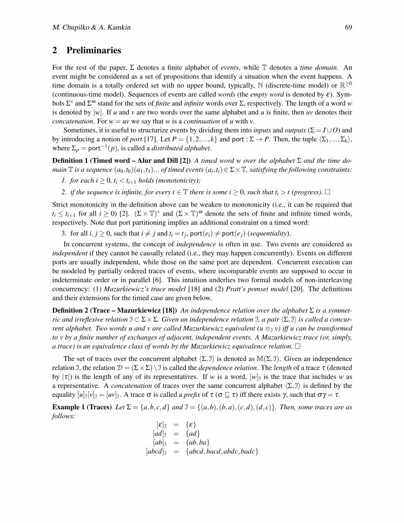
M. Chupilko & A. Kamkin 69
2 Preliminaries
For the rest of the paper, Σ denotes a finite alphabet of events, while T denotes a time domain. Anevent might be considered as a set of propositions that identify a situation when the event happens. Atime domain is a totally ordered set with no upper bound, typically, N (discrete-time model) or R≥0
(continuous-time model). Sequences of events are called words (the empty word is denoted by ε). Sym-bols Σ∗ and Σω stand for the sets of finite and infinite words over Σ, respectively. The length of a word wis denoted by |w|. If u and v are two words over the same alphabet and u is finite, then uv denotes theirconcatenation. For w = uv we say that w is a continuation of u with v.
Sometimes, it is useful to structurize events by dividing them into inputs and outputs (Σ = I∪O) andby introducing a notion of port [17]. Let P = {1,2, ...,k} and port : Σ→ P. Then, the tuple 〈Σ1, ...,Σk〉,where Σp = port−1(p), is called a distributed alphabet.
Definition 1 (Timed word – Alur and Dill [2]) A timed word w over the alphabet Σ and the time do-main T is a sequence (a0, t0)(a1, t1)... of timed events (ai, ti)∈ Σ×T, satisfying the following constraints:
1. for each i≥ 0, ti < ti+1 holds (monotonicity);
2. if the sequence is infinite, for every t ∈ T there is some i≥ 0, such that ti > t (progress). �Strict monotonicity in the definition above can be weaken to monotonicity (i.e., it can be required thatti ≤ ti+1 for all i ≥ 0) [2]. (Σ×T)∗ and (Σ×T)ω denote the sets of finite and infinite timed words,respectively. Note that port partitioning implies an additional constraint on a timed word:
3. for all i, j ≥ 0, such that i 6= j and ti = t j, port(ei) 6= port(e j) (sequentiality).In concurrent systems, the concept of independence is often in use. Two events are considered as
independent if they cannot be causally related (i.e., they may happen concurrently). Events on differentports are usually independent, while those on the same port are dependent. Concurrent execution canbe modeled by partially ordered traces of events, where incomparable events are supposed to occur inindeterminate order or in parallel [6]. This intuition underlies two formal models of non-interleavingconcurrency: (1) Mazurkiewicz’s trace model [18] and (2) Pratt’s pomset model [20]. The definitionsand their extensions for the timed case are given below.
Definition 2 (Trace – Mazurkiewicz [18]) An independence relation over the alphabet Σ is a symmet-ric and irreflexive relation I⊂ Σ×Σ. Given an independence relation I, a pair 〈Σ,I〉 is called a concur-rent alphabet. Two words u and v are called Mazurkiewicz equivalent (u ≡I v) iff u can be transformedto v by a finite number of exchanges of adjacent, independent events. A Mazurkiewicz trace (or, simply,a trace) is an equivalence class of words by the Mazurkiewicz equivalence relation. �
The set of traces over the concurrent alphabet 〈Σ,I〉 is denoted as M(Σ,I). Given an independencerelation I, the relation D= (Σ×Σ)\I is called the dependence relation. The length of a trace τ (denotedby |τ|) is the length of any of its representatives. If w is a word, [w]I is the trace that includes w asa representative. A concatenation of traces over the same concurrent alphabet 〈Σ,I〉 is defined by theequality [u]I[v]I = [uv]I. A trace σ is called a prefix of τ (σ v τ) iff there exists γ , such that σγ = τ .
Example 1 (Traces) Let Σ = {a,b,c,d} and I = {(a,b),(b,a),(c,d),(d,c)}. Then, some traces are asfollows:
[ε]I = {ε}[ad]I = {ad}[ab]I = {ab,ba}
[abcd]I = {abcd,bacd,abdc,badc}
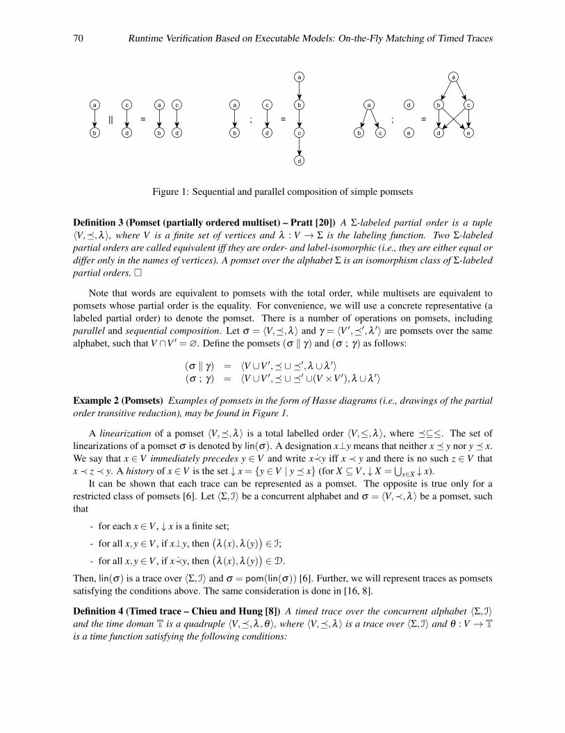
70 Runtime Verification Based on Executable Models: On-the-Fly Matching of Timed Traces
Figure 1: Sequential and parallel composition of simple pomsets
Definition 3 (Pomset (partially ordered multiset) – Pratt [20]) A Σ-labeled partial order is a tuple〈V,�,λ 〉, where V is a finite set of vertices and λ : V → Σ is the labeling function. Two Σ-labeledpartial orders are called equivalent iff they are order- and label-isomorphic (i.e., they are either equal ordiffer only in the names of vertices). A pomset over the alphabet Σ is an isomorphism class of Σ-labeledpartial orders. �
Note that words are equivalent to pomsets with the total order, while multisets are equivalent topomsets whose partial order is the equality. For convenience, we will use a concrete representative (alabeled partial order) to denote the pomset. There is a number of operations on pomsets, includingparallel and sequential composition. Let σ = 〈V,�,λ 〉 and γ = 〈V ′,�′,λ ′〉 are pomsets over the samealphabet, such that V ∩V ′ =∅. Define the pomsets (σ ‖ γ) and (σ ; γ) as follows:
(σ ‖ γ) = 〈V ∪V ′,� ∪�′,λ ∪λ ′〉(σ ; γ) = 〈V ∪V ′,� ∪�′ ∪(V ×V ′),λ ∪λ ′〉
Example 2 (Pomsets) Examples of pomsets in the form of Hasse diagrams (i.e., drawings of the partialorder transitive reduction), may be found in Figure 1.
A linearization of a pomset 〈V,�,λ 〉 is a total labelled order 〈V,≤,λ 〉, where �⊆≤. The set oflinearizations of a pomset σ is denoted by lin(σ). A designation x⊥y means that neither x� y nor y� x.We say that x ∈ V immediately precedes y ∈ V and write x≺y iff x ≺ y and there is no such z ∈ V thatx≺ z≺ y. A history of x ∈V is the set ↓ x = {y ∈V | y� x} (for X ⊆V , ↓ X =
⋃x∈X ↓ x).
It can be shown that each trace can be represented as a pomset. The opposite is true only for arestricted class of pomsets [6]. Let 〈Σ,I〉 be a concurrent alphabet and σ = 〈V,≺,λ 〉 be a pomset, suchthat
- for each x ∈V , ↓ x is a finite set;
- for all x,y ∈V , if x⊥y, then(λ (x),λ (y)
)∈ I;
- for all x,y ∈V , if x≺y, then(λ (x),λ (y)
)∈D.
Then, lin(σ) is a trace over 〈Σ,I〉 and σ = pom(lin(σ)) [6]. Further, we will represent traces as pomsetssatisfying the conditions above. The same consideration is done in [16, 8].
Definition 4 (Timed trace – Chieu and Hung [8]) A timed trace over the concurrent alphabet 〈Σ,I〉and the time doman T is a quadruple 〈V,�,λ ,θ〉, where 〈V,�,λ 〉 is a trace over 〈Σ,I〉 and θ : V → Tis a time function satisfying the following conditions:
M. Chupilko & A. Kamkin 71
Figure 2: Scheme for checking conformance between implementation and specification
1. for all x,y ∈V , if x≺ y, then θ(x)< θ(y) (causality);
2. if the trace is infinite, then for every t ∈ T there is a cut C ⊆ V , such that minx∈C{θ(x)} ≥ t(progress). �
The set of timed traces over the concurrent alphabet 〈Σ,I〉 and the time domain T is denoted asMθ (Σ,I,T). Note that timed words are a particular case of timed traces. Given a non-empty timed traceσ = 〈V,�,λ ,θ〉, begin(σ) =minx∈V{θ(x)} and end(σ) =maxx∈V{θ(x)} (if σ is infinite, end(σ) = ∞);σ[t,t+∆t] is a sub-trace of σ consisting of x ∈ V , such that θ(x) ∈ [t, t +∆t]. Let TI(T) be the set of timeintervals over the time domain T (i.e., TI(T) = {[t, t +∆t] | t, t +∆t ∈ T}).Definition 5 (Time interval trace) A time interval trace over the concurrent alphabet 〈Σ,I〉 and thetime doman T is a quadruple σ = 〈V,�,λ ,δ 〉, where 〈V,�,λ 〉 is a trace over 〈Σ,I〉 and δ : V → TI(T)is a function that associates a time interval to a vertex. The language of the time interval trace σ is theset L(σ) = {〈V,�,λ ,θ〉 ∈Mθ (Σ,I,T) | ∀x ∈V . θ(x) ∈ δ (x)}. �
The set of time interval traces over the concurrent alphabet 〈Σ,I〉 and the time domain T is denotedas Mδ (Σ,I,T). Futher we will deal with pairs consisting of a timed trace σ and a time interval trace σδ ,such that σ ∈ L(σδ ). Such a pair can be expressed as a quintuple 〈V,�,λ ,θ ,δ 〉 and is referred to as anextended time interval trace. The set of such traces is denoted as Mθδ (Σ,I,T).
3 Runtime Verification with Executable Models
A timed word (more precisely, a timed trace with an empty partial order) describes a concrete executionof the implementation under verification, while an extended time interval trace being more general canbe considered as a specification behavior. Our goal is to check whether an implementation timed wordwI ∈ (Σ×T)∗(ω) is conforming to a specification trace σS ∈Mθδ (Σ,I,T). Note that we are interested inon-the-fly checking, which means that a monitor “lives” in time and matches two traces in an event-drivenfashion. Trace acceptance (verdict) at a given time point has a three-valued semantics [5]: (1) f alse (aninconsistency has been detected), (2) true (the implementation execution has been completed and itstrace is conforming to the specification trace) and (3) inconclusive (the monitoring is in progress and noinconsistency has been found).
To make it clear where a specification trace comes from, an additional explanation should be pro-vided. As it was said in the introduction, a system specification is represented in the executable form.
72 Runtime Verification Based on Executable Models: On-the-Fly Matching of Timed Traces
Hence, it can be executed and its executions (as ones of the implementation) are represented as timedwords. The straightforward testing of the equality of two timed words is often inadequate and makessense only for time-accurate specifications. Specifications are usually more abstract than implementa-tions, especially in terms of event ordering and timing. Assumptions on the specification abstractnessgeneralize a concrete timed word to the extended time interval trace softening the conformance checking.Formally, abstraction is a map A : (Σ×T)∗(ω)→Mθδ (Σ,I,T), such that w is conforming to A(w) forevery w ∈ (Σ×T)∗(ω). A specification timed word wS is mapped into the extended time interval traceA(wS) = σS. Then, it is checked whether an implementation word wI is conforming to the constructedspecification trace σS. This scheme is illustrated in Figure 2. Technical details can be found in Section 4.
3.1 Conformance Relation
The next definition formalizes system executions in terms of timed traces. It also singles out input andoutput sequences as particular cases of traces corresponding to stimuli to a system and its reactions,respectively. System behavior is then abstractly defined as a map of inputs to outputs.
Definition 6 (Execution trace) An execution trace over the concurrent alphabet 〈Σ,I〉 and the time do-main T is a timed trace with the empty partial order (i.e., a trace of the kind 〈V,∅,λ ,θ〉). If Σ = I∪O,then execution traces over the alphabet I are called input sequences, while execution traces over thealphabet O are referred to as output sequences. �
Note that the empty partial order in execution traces reflects a fact that an implementation is a “blackbox”, and, therefore, the cause-effect relation between its events is unknown. The sets of input and outputsequences are designated by Iθ (Σ,T) and Oθ (Σ,T), respectively. Hereinafter, we will use the shortenednotations: I= Iθ (Σ,T) and O=Oθ (Σ,T).
Definition 7 (Behavior) Deterministic timed behavior (or, simply, behavior) over the alphabet Σ andthe time domain T is a (partial) map B : I×T→O satisfying the following constraints:
- for every w ∈ I and t ∈ T, end(B(w, t)
)≤ t holds (future uncertainty);
- for every w ∈ I and t ∈ T, B(w, t) =B(w[0,t], t) holds (time directivity);
- for every w ∈ I and every t ∈ T, there exists wv ∈ I, a continuation of w, and ∆t ≥ 0, such thatend(B(wv, t +∆t)
)≥ t (liveness). �
The idea behind the concept is clear. Behavior describes how an input sequence is transformed intothe output sequence taking into account an observation time point. Usually, when an input sequence isapplied, then after a finite number of time units (counting from the last input time) the output sequenceis fully observed and is ready to be checked. Such post-mortem analysis is not however what we areinterested in. There are two reasons for that: (1) to ease the analysis, an execution should be terminatedas soon as a failure is detected; (2) storing long sequences in memory is costly. Providing that a referencemodel is available, consider how it can be used for checking implementation behavior in runtime. Letus extend the definition above by allowing a specification to return extended time interval traces over theoutputs (not concrete sequences as it is required). Denote the set of such traces as Oθδ .
Given an output trace 〈V,�,λ ,θ ,δ 〉 ∈ Oθδ , define two functions, ∆t±, such that for every x ∈ V ,δ (x) = [θ(x)−∆t−(x),θ(x)+∆t+(x)]. Assume that functions ∆t± are bounded (i.e., there exist constants∆T± > 0, such that |∆t±(x)| ≤ ∆T± for all x ∈ V ). Assume also that values ∆t±(x) depend only onthe event not on the vertex itself (i.e., ∆t±(x) = ∆t±(λ (x))). Let I and S be an implementation andspecification behavior, respectively. Given an input sequence w ∈ I, a time point t ∈ T, let us consider

M. Chupilko & A. Kamkin 73
Figure 3: Conformance between implementation and specification
implementation and specification outputs: I(w, t) = 〈VI,∅,λI,θI〉 and S(w, t) = 〈VS,�S,λS,θS,δS〉. Letus introduce the following notations:
past∆tI (w, t) = {y ∈ I(w, t) | θI(y)≤
(t−∆t−(y)
)};
pastI(w, t) = {y ∈ I(w, t) | θI(y)≤ t};past∆t
S (w, t) = {x ∈ S(w, t) | θS(x)≤(t−∆t+(x)
)};
pastS(w, t) = {x ∈ S(w, t) | θS(x)≤ t};match(x,y) =
(λI(y) = λS(x)
)∧(θI(y) ∈ δS(x)
).
Definition 8 (Conformance relation) The implementation behavior I is said to be conforming to thespecification behavior S iff domI= domS and for all w ∈ domS and t ∈ T, there is a relation M(w, t)⊆{(x,y) ∈ pastS(w, t)×pastI(w, t) |match(x,y)} (called a matching relation), such that:
1. M(w, t) is a one-to-one relation;
2. for each x ∈ past∆tS (w, t), there is y ∈ pastI(w, t), such that (x,y) ∈M(w, t);
3. for each y ∈ past∆tI (w, t), there is x ∈ pastS(w, t), such that (x,y) ∈M(w, t);
4. for all (x,y),(x′,y′) ∈M(w, t), if x≺ x′, then θI(y)≤ θI(y′).
If for some w∈ I and t ∈T the abovementioned properties are violated, then I is said to be not conformingto S, and w[0,t] is referred to as a counterexample. �
Figure 3 illustrates the conformance relation definition for a particular input sequence (being unim-portant it is not shown in the picture) and observation time (t = 4). The upper part of the figure is adrawing of the implementation outputs (black circles with white labels: b, a and c). The lower partdepicts the specification outputs (white circles with black labels: a, b, c and d). Let us denote the trace
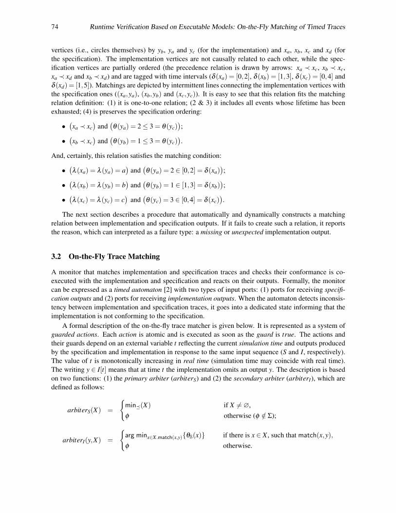
74 Runtime Verification Based on Executable Models: On-the-Fly Matching of Timed Traces
vertices (i.e., circles themselves) by yb, ya and yc (for the implementation) and xa, xb, xc and xd (forthe specification). The implementation vertices are not causally related to each other, while the spec-ification vertices are partially ordered (the precedence relation is drawn by arrows: xa ≺ xc, xb ≺ xc,xa ≺ xd and xb ≺ xd) and are tagged with time intervals (δ (xa) = [0,2], δ (xb) = [1,3], δ (xc) = [0,4] andδ (xd) = [1,5]). Matchings are depicted by intermittent lines connecting the implementation vertices withthe specification ones ((xa,ya), (xb,yb) and (xc,yc)). It is easy to see that this relation fits the matchingrelation definition: (1) it is one-to-one relation; (2 & 3) it includes all events whose lifetime has beenexhausted; (4) is preserves the specification ordering:
•(xa ≺ xc
)and
(θ(ya) = 2≤ 3 = θ(yc)
);
•(xb ≺ xc
)and
(θ(yb) = 1≤ 3 = θ(yc)
).
And, certainly, this relation satisfies the matching condition:
•(λ (xa) = λ (ya) = a
)and
(θ(ya) = 2 ∈ [0,2] = δ (xa)
);
•(λ (xb) = λ (yb) = b
)and
(θ(yb) = 1 ∈ [1,3] = δ (xb)
);
•(λ (xc) = λ (yc) = c
)and
(θ(yc) = 3 ∈ [0,4] = δ (xc)
).
The next section describes a procedure that automatically and dynamically constructs a matchingrelation between implementation and specification outputs. If it fails to create such a relation, it reportsthe reason, which can interpreted as a failure type: a missing or unexpected implementation output.
3.2 On-the-Fly Trace Matching
A monitor that matches implementation and specification traces and checks their conformance is co-executed with the implementation and specification and reacts on their outputs. Formally, the monitorcan be expressed as a timed automaton [2] with two types of input ports: (1) ports for receiving specifi-cation outputs and (2) ports for receiving implementation outputs. When the automaton detects inconsis-tency between implementation and specification traces, it goes into a dedicated state informing that theimplementation is not conforming to the specification.
A formal description of the on-the-fly trace matcher is given below. It is represented as a system ofguarded actions. Each action is atomic and is executed as soon as the guard is true. The actions andtheir guards depend on an external variable t reflecting the current simulation time and outputs producedby the specification and implementation in response to the same input sequence (S and I, respectively).The value of t is monotonically increasing in real time (simulation time may coincide with real time).The writing y ∈ I[t] means that at time t the implementation omits an output y. The description is basedon two functions: (1) the primary arbiter (arbiterS) and (2) the secondary arbiter (arbiterI), which aredefined as follows:
arbiterS(X) =
{min�(X) if X 6=∅,φ otherwise (φ /∈ Σ);
arbiterI(y,X) =
{arg minx∈X .match(x,y){θS(x)} if there is x ∈ X , such that match(x,y),φ otherwise.
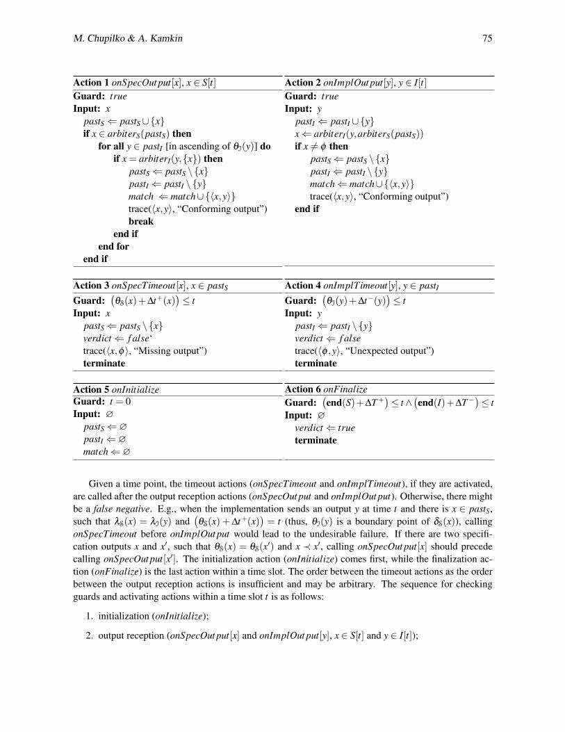
M. Chupilko & A. Kamkin 75
Action 1 onSpecOut put[x], x ∈ S[t]Guard: trueInput: x
pastS⇐ pastS∪{x}if x ∈ arbiterS(pastS) then
for all y ∈ pastI [in ascending of θI(y)] doif x = arbiterI(y,{x}) then
pastS⇐ pastS \{x}pastI ⇐ pastI \{y}match ⇐ match∪{〈x,y〉}trace(〈x,y〉, “Conforming output”)break
end ifend for
end if
Action 2 onImplOut put[y], y ∈ I[t]Guard: trueInput: y
pastI ⇐ pastI ∪{y}x⇐ arbiterI(y,arbiterS(pastS))if x 6= φ then
pastS⇐ pastS \{x}pastI ⇐ pastI \{y}match⇐ match∪{〈x,y〉}trace(〈x,y〉, “Conforming output”)
end if
Action 3 onSpecTimeout[x], x ∈ pastSGuard:
(θS(x)+∆t+(x)
)≤ t
Input: xpastS⇐ pastS \{x}verdict⇐ f alse‘trace(〈x,φ〉, “Missing output”)terminate
Action 4 onImplTimeout[y], y ∈ pastIGuard:
(θI(y)+∆t−(y)
)≤ t
Input: ypastI ⇐ pastI \{y}verdict⇐ f alsetrace(〈φ ,y〉, “Unexpected output”)terminate
Action 5 onInitializeGuard: t = 0Input: ∅
pastS⇐∅pastI ⇐∅match⇐∅
Action 6 onFinalizeGuard:
(end(S)+∆T+
)≤ t∧
(end(I)+∆T−
)≤ t
Input: ∅verdict⇐ trueterminate
Given a time point, the timeout actions (onSpecTimeout and onImplTimeout), if they are activated,are called after the output reception actions (onSpecOut put and onImplOut put). Otherwise, there mightbe a false negative. E.g., when the implementation sends an output y at time t and there is x ∈ pastS,such that λS(x) = λI(y) and
(θS(x) +∆t+(x)
)= t (thus, θI(y) is a boundary point of δS(x)), calling
onSpecTimeout before onImplOut put would lead to the undesirable failure. If there are two specifi-cation outputs x and x′, such that θS(x) = θS(x′) and x ≺ x′, calling onSpecOut put[x] should precedecalling onSpecOut put[x′]. The initialization action (onInitialize) comes first, while the finalization ac-tion (onFinalize) is the last action within a time slot. The order between the timeout actions as the orderbetween the output reception actions is insufficient and may be arbitrary. The sequence for checkingguards and activating actions within a time slot t is as follows:
1. initialization (onInitialize);
2. output reception (onSpecOut put[x] and onImplOut put[y], x ∈ S[t] and y ∈ I[t]);

76 Runtime Verification Based on Executable Models: On-the-Fly Matching of Timed Traces
3. timeouts (onSpecTimeout[x] and onImplTimeout[y], x ∈ pastS and y ∈ pastI);
4. finalization (onFinalize).Note that when we say that some property ϕ holds at time t, we mean that ϕ holds after all of the actionsactivated at time t have completed. For a multi-port system, the monitor can be decomposed into anumber of loosely connected sub-monitors serving individual ports. If the specification abstracts awayfrom the inter-port dependencies, the sub-monitors are fully independent and can work in parallel.
Statement 1 (Monitor correctness) An input sequence w is a counterexample for I being conformingto S iff the monitor terminates with verdict = f alse. �
Rigorously speaking, the termination condition(end(I)+∆T−
)≤ t cannot be checked for “black-
box” implementations (a monitor is not able to identify whether the implementation is quiescent or ac-tive). However, for some types of systems (in particular, systems with covergent behavior) the conditioncan be approximated with a checkable one.
Definition 9 (Convergent behavior) The behavior B : I×T→O is called convergent iff the followingconditions are met:
- for every finite w ∈ I, there exists T (w) ∈ T, called the stabilization time, such that for any t ≥T (w), B(w, t) =B
(w,T (w)
)(B(w) denotes B
(w,T (w)
));
- for every t ∈ T, B(ε, t) = ε holds (the initial state is quiescent);
- for every finite w,v ∈ I, such that v 6= ε and t0 = begin(v)> T (w), t ≥ t0 and ∆t ∈ T,{B(w(v+∆t), t +∆t
)[t0+∆t,t+∆t] =B(wv, t)[t0,t]+∆t,
t0 ≤ begin(B(wv)[T (w),∞)), if B(·)[·) 6= ε;
where w+∆t denotes the sequence constructed from w by adding ∆t to each time stamp of w(quiescent states are stable). �
Assuming that the implementation under verification is convergent, the termination condition maybe expressed as follows: (
T (w)≤ t)∧((
end(I[0,T (w)])+∆T−)≤ t).
3.3 Specifications with Optional Outputs
There are systems where operations in some situations terminate other operations, conflicting with themand of a lower priority. For example, a write operation can be cancelled by another write operationtargeted at the same location and started right after the previous one. Due to abstractness, a specificationis not able to express precisely under what conditions operations are cancelled and their output is notsent outside. Taking into account such problems, the definition of the specification behavior should beextended. Assume there is an unary relation ♦ ⊆ VS marking cancellable outputs (the complement of ♦is denoted by �): if ♦x, then the output is optional (it might be cancelled, but the cancellation conditionis unknown or inexpressible in specification terms); if �x, then the output is obligatory (it cannot becancelled). Note that if some action is cancelled, then all dependent actions are cancelled either.
Definition 10 (Conformance relation for specifications with optional outputs) The implementation be-havior I is said to be conforming to the specification behavior with optional outputs S iff domI =domS and for all w ∈ domS and t ∈ T, there is a relation M(w, t)⊆ {(x,y) ∈ pastS(w, t)×pastI(w, t) |match(x,y)}, such that:

M. Chupilko & A. Kamkin 77
1. M(w, t) is a one-to-one relation;
2. for each x ∈ past∆tS (w, t),
- if �x, then there is y ∈ pastI(w, t), such that (x,y) ∈M(w, t);- if ♦x, then either there is y∈ pastI(w, t), such that (x,y)∈M(w, t), or for each x′ ∈ pastS(w, t),
if x� x′, then there is no y ∈ pastI(w, t), such that (x′,y) ∈M(w, t).
3. for each y ∈ past∆tI (w, t), there is x ∈ pastS(w, t), such that (x,y) ∈M(w, t);
4. for all (x,y),(x′,y′) ∈M(w, t), if x≺ x′, then θI(y)≤ θI(y′). �Checking conformance to specifications with optional outputs can be done with a few modifications
of the monitor described above. In onSpecTimeout, it should be checked whether an event x is optional(the action fails only if x is obligatory). The most difficult part is to track that all events dependenton the cancelled one are also cancelled. Assume that there is ∆Tdep ∈ T, such that for all x,x′ ∈ VS, if|θS(x)−θS(x′)|>∆Tdep, then x⊥x′. To describe the monitor, let us introduce a predicate cancelledS(x) =(∃x′ ∈ termS . x′ � x
)and a modified version of the primary arbiter: arbiterS(X) =min�(X \ termS).
Action 7 onSpecOut put[x], x ∈ S[t]Guard: trueInput: x
pastS⇐ pastS∪{x}if cancelled(x) then
termS⇐ termS∪{x}else
...end if
Action 8 onSpecTimeout[x], x ∈ (pastS \ termS)
Guard: (θS(x)+∆t+(x))≤ tInput: x
if �x then...
elsetermS⇐ termS∪{x}
end if
Action 9 onTermTimeout[x], x ∈ termS
Guard:(θS(x)+∆Tdep
)≤ t
Input: xpastS⇐ pastS \{x}termS⇐ termS \{x}
Action 10 onInitializeGuard: t = 0Input: ∅
termS⇐∅...
4 Tool Support and Experience
The proposed approach to runtime verification has been implemented in a C++ library named C++TESKTesting ToolKit [1]. The library provides users with classes and macros for automated development oftest system components, including reference models, monitors (test oracles), stimuli generators, coveragetrackers, etc. C++TESK supports testing and monitoring of both hardware and software systems but hasbeen mainly used for hardware designs (namely, for simulation-based verification of microprocessorunits). Note that hardware is usually developed in hardware description languages (HDLs), like Verilogand VHDL, and can be executed (simulated) in a special environment, called HDL simulator. TheC++TESK facilities for developing reference models of hardware designs (and, consequently, runtimemonitors) include means for sending and receiving data packages, forking and joining concurrent threads,modeling time delays and specifying order between data packages. Some of the primitives (the mostimportant within the scope of the paper) are as follows (the syntax here differs from the original one,used in the toolkit):
78 Runtime Verification Based on Executable Models: On-the-Fly Matching of Timed Traces
• delay(n) — models a time delay (as an observable outcome, it increments the current time valueby n time units);
• recv(in):pkg — waits until an input package is received at a given input port (in); then, returnsthat package (pkg);
• send(out, pkg, opt) — sends an output package (pkg) via a given output port (out) specify-ing whether the package is obligatory or optional (opt);(Note that every time a package is sent outside, it is tagged with time interval [t−∆t−, t +∆t+],where t is the sending start time and ∆t± are user-defined parameters of the transmission port.)
• depends(pkg1, pkg2) — states that an output package (pkg1) depends on or causally related tosome other package (pkg2), input or output.(This probably answers the question raised in the beginning of Section 3 of where a specificationtrace, namely partial ordering of its events, is taken from.)
Differences in hardware complexity, verification purposes and amounts of resources lead to the vari-ety of model types and model abstraction levels. Abstraction is a well-known way for fighting complexityand facilitating model development. Though the verification quality is likely to be lower in case of sim-pler reference models, if there is a strict deadline (and it is often so), there is no other way out. Eventordering and timing are the main subjects for abstraction in hardware designs and other concurrent time-dependent systems. We use the following classification of the reference models according to the timemodeling accuracy: (1) untimed models (represent only general information on the cause-effect relationof their inputs and outputs, while the timing is not modelled at all: ∆t± = ∞), (2) time-approximate mod-els (contain the detailed specification of the event ordering, including some internal arbitration schemes,but the timing is approximate: ∆t± ≤ T , where T has a value of several tens of time units) and (3) time-accurate models (implement the exact, or almost exact, event ordering and timing: ∆t± ≤ 1).
The proposed methodology has been used for verification of a number of units of different industrialmicroprocessors. Our experience was originally presented in [9], and since then we have verified a tablelookup unit, an l2-cache bank controller and an instruction buffer. Also, testbenches and monitors forseveral previously tested components (a north bridge data switch and a memory access unit) requiredimprovement according to the modifications of the units. The newest information of the approach ap-plication is shown in Table 1. As it can be seen from the table, the methodology supports runtimeverification by means of abstract models (being available at early design stages) and, at the same time,by means of up to time-accurate models (being available typically at finishing design stages). Moreover,the approach allows reusing reference models across the hardware development cycle, which is reallyimportant in the industrial settings.
The first version of C++TESK supported only accurate reference models (it was required that amodel knows the exact ordering of events on each of the output ports). Having received feedback fromC++TESK users (everyone is welcome to join the community), the toolkit has been modified. Mostly,it concerns a problem of lack of unit-level specifications even for almost finished hardware designs.It is impossible to create an accurate model without detailed knowledge of the unit functionality andtiming. Regular interviewing of engineers takes a lot of time and is inconvenient. Two major solutionsof the problem have been proposed besides forcing the developers to write the specifications. The firstsolution is to reuse parts of a more complicated system-level model (emulating behavior of the wholemicroprocessor). Though such parts are rather abstract (as a rule, system-level models are developed inan untimed manner), they are really useful for early-stage verification. The second solution is to developapproximate reference models by means of C++TESK and to refine them if necessary.
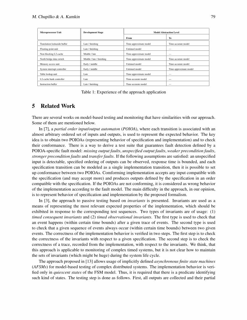
M. Chupilko & A. Kamkin 79
Microprocessor Unit Development Stage Model Abstraction Level
From To
Translation lookaside buffer Late / finishing Time-approximate model Time-accurate model
Floating point unit Late / finishing Untimed model —
Non-blocking L2-cache Middle / late Time-approximate model —
North bridge data switch Middle / late / finishing Time-approximate model Time-accurate model
Memory access unit Early / middle Untimed model Time-accurate model
System interrupt controller Early / middle Untimed model Time-approximate model
Table lookup unit Late Time-approximate model —
L2-cache bank controller Late Time-accurate model —
Instruction buffer Late / finishing Time-accurate model —
Table 1: Experience of the approach application
5 Related Work
There are several works on model-based testing and monitoring that have similarities with our approach.Some of them are mentioned below.
In [7], a partial order input/output automaton (POIOA), where each transition is associated with analmost arbitrary ordered set of inputs and outputs, is used to represent the expected behavior. The keyidea is to obtain two POIOAs (representing behavior of specification and implementation) and to checktheir conformance. There is a way to derive a test suite that guarantees fault detection defined by aPOIOA-specific fault model: missing output faults, unspecified output faults, weaker precondition faults,stronger precondition faults and transfer faults. If the following assumptions are satisfied: an unspecifiedinput is detectable, specified ordering of outputs can be observed, response time is bounded, and eachspecification transition can be modeled as a single implementation transition, then it is possible to setup conformance between two POIOAs. Comforming implementation accepts any input compatible withthe specification (and may accept more) and produces outputs defined by the specification in an ordercompatible with the specification. If the POIOAs are not conforming, it is considered as wrong behaviorof the implementation according to the fault model. The main difficulty in the approach, in our opinion,is to represent behavior of specification and implementation by the proposed formalism.
In [3], the approach to passive testing based on invariants is presented. Invariants are used as ameans of representing the most relevant expected properties of the implementation, which should beexhibited in response to the corresponding test sequences. Two types of invariants are of usage: (1)timed consequent invariants and (2) timed observational invariants. The first type is used to check thatan event happens (within certain time bounds) after a given trace of events. The second type is usedto check that a given sequence of events always occur (within certain time bounds) between two givenevents. The correctness of the implementation behavior is verified in two steps. The first step is to checkthe correctness of the invariants with respect to a given specification. The second step is to check thecorrectness of a trace, recorded from the implementation, with respect to the invariants. We think, thatthis approach is applicable to monitoring of complex timed systems, but it is not clear how to maintainthe sets of invariants (which might be huge) during the system life cycle.
The approach proposed in [13] allows usage of implicitly defined asynchronous finite state machines(AFSMs) for model-based testing of complex distributed systems. The implementation behavior is veri-fied only in quiescent states of the FSM model. Thus, it is required that there is a predicate identifyingsuch kind of states. The testing step is done as follows. First, all outputs are collected and their partial
80 Runtime Verification Based on Executable Models: On-the-Fly Matching of Timed Traces
order is determined. Then, all possible linearizations of the events are enumerated and checked. If allof them fail (with respect to the specification), then the implementation is not conforming to the specifi-cation. As checking is performed in quiescent states only, the approach is hardly applicable to runtimemonitoring (where there may be arbitrary input sequences, and such states are rarely visited).
6 Conclusion
On-the-fly analysis of system behavior is an integral part of dynamic verification of software and hard-ware systems. A lot of formalisms have been proposed to express correctness properties for systems ofdifferent types, and a great number of methods have been suggested to check whether system executionsare conforming to the specified properties. None of them is perfect, we think, but all together they covera vast spectrum of verification and monitoring tasks. Among the variety of specification approaches, ex-ecutable models, written in high-level programming languages, have a significant niche. First of all, suchmodels are rather universal and allow expressing a broad range of behavioral and structural properties.Besides, programming languages (especially general-purpose languages, like C and C++) are widelyspread in the engineering community.
Our work focuses on using executable models for runtime verification of reactive systems, including,in particular, time-dependent systems. The problem is not as simple as it looks at first sight. The naivechecking that a system and its model produce the same outputs at the same time is inadequate in themajority of cases. The model may abstract away from many features implemented in the system underverification such as event ordering and accurate timing (at least it should be abstracted from the imple-mentation bugs). We suppose that conformance relations used for runtime verification can be configuredin several ways: (1) by introducing an independency relation over the model events, (2) by extendingtime points of the model outputs to time intervals and, finally, (3) by marking some of the model outputsas being optional.
Basing on this idea, we have developed a method for system monitoring and proved its correctness.The formalization is based on the theory of traces and partially ordered multisets. The method has beenimplemented in C++TESK, an open-source toolkit for hardware modeling, analysis and verification,and has been successfully used in about 10 projects on simulation-based verification of microprocessorunits. Our future research is aiming at failure diagnostics, which is a deeper analysis of specification andimplementation traces being carried out offline. The goal is to explain what in particular went wrongduring the monitoring and give a hint to developers where the bugs are localized.
7 Bibliography
References
[1] C++TESK Homepage. Available at http://forge.ispras.ru/projects/cpptesk-toolkit/.
[2] R. Alur & D.L. Dill (1994): A Theory of Timed Automata. Theoretical Computer Science 126(2), pp. 183–235, doi:10.1016/0304-3975(94)90010-8.
[3] C. Andres, M.G. Merayo & M. Nunez (2012): Formal Passive Testing of Timed Systems: Theory and Tools.Software Testing, Verification & Reliability 22(6), pp. 365–405, doi:10.1002/stvr.1464.
[4] H. Barringer, D. Rydeheard & K. Havelund (2007): Rule Systems for Run-Time Monitoring: From Eagle toRuleR. In: Proceedings of 7th International Workshop on Runtime Verification. Revised Selected Papers, pp.111–125, doi:10.1007/978-3-540-77395-5 10.

M. Chupilko & A. Kamkin 81
[5] A. Bauer, M. Leucker & C. Schallhart (2011): Runtime Verification for LTL and TLTL. ACM Transactionson Software Engineering and Methodology 20(4), pp. 14:1–14:64, doi:10.1145/2000799.2000800.
[6] B. Bloom & M. Kwiatkowska (1991): Trade-offs in True Concurrency: Pomsets and Mazurkiewicz Traces.Technical Report TR 91-1223, Cornell University.
[7] G. von Bochmann, S.Haar, C.Jard & G.-V. Jourdan (2008): Testing Systems Specified as Partial Order In-put/Output Automata. In: Proceedings of the 20th IFIP TC 6/WG 6.1 International Conference on Testingof Software and Communicating Systems: 8th International Workshop, TestCom ’08 / FATES ’08, Springer-Verlag, Berlin, Heidelberg, pp. 169–183, doi:10.1007/978-3-540-68524-1-13.
[8] D.V. Chieu & D.V. Hung (2012): Timed Traces and Their Applications in Specification and Verification ofDistributed Real-time Systems. In: Proceedings of the Third Symposium on Information and CommunicationTechnology, pp. 31–40, doi:10.1145/2350716.2350723.
[9] M. Chupilko & A. Kamkin (2011): A TLM-Based Approach to Functional Verification of Hardware Compo-nents at Different Abstraction Levels. In: Proceedings of the 12th Latin-American Test Workshop, pp. 1–6,doi:10.1109/LATW.2011.5985902.
[10] E.M. Clarke, O. Grumberg & D.A. Peled (1999): Model Checking. The MIT Press.[11] R.M. Hierons, K. Bogdanov, J.P.Bowen, R. Cleaveland, J. Derrick, J. Dick, M. Gheorghe, M. Har-
man, K. Kapoor, P. Krause, G. Luttgen, A.J.H. Simons, S. Vilkomir, M.R. Woodward & H. Zedan(2009): Using Formal Specifications to Support Testing. ACM Computing Surveys 41(2), pp. 9:1–9:76,doi:10.1145/1459352.1459354.
[12] V.P. Ivannikov, A.S. Kamkin, A.S. Kossatchev, V.V. Kuliamin & A.K. Petrenko (2007): The Use of ContractSpecifications for Representing Requirements and for Functional Testing of Hardware Models. Programmingand Computer Software 33(5), pp. 272–282, doi:10.1134/S0361768807050039.
[13] V. Kuliamin, A. Petrenko, N. Pakoulin, A. Kossatchev & I. Bourdonov (2003): Integration of Functionaland Timed Testing of Real-Time and Concurrent Systems. In M. Broy & A. Zamulin, editors: Perspectivesof System Informatics, Lecture Notes in Computer Science 2890, Springer Berlin Heidelberg, pp. 450–461,doi:10.1007/978-3-540-39866-0-45.
[14] W.K. Lam (2005): Hardware Design Verification: Simulation and Formal Method-Based Approaches. Pren-tice Hall.
[15] J. Laski & W. Stanley (2009): Software Verification and Analysis: An Integrated, Hands-On Approach.Springer.
[16] M. Leucker (2000): On Model Checking Synchronised Hardware Circuits. In: Proceedings of the 6th
Asian Computing Science Conference, Lecture Notes in Computer Science 1961, Springer, pp. 182–198,doi:10.1007/3-540-44464-5 14.
[17] G. Luo, R. Dssouli, G. von Bochmann, P. Venkataram & A. Ghedamsi (1993): Generating SynchronizableTest Sequences Based On Finite State Machine with Distributed Ports. In: Proceedings of the IFIP SixthInternational Workshop on Protocol Test Systems, pp. 53–68.
[18] A. Mazurkiewicz (1987): Trace Theory. In: Advances in Petri Nets 1986, Part II on Petri Nets: Applicationsand Relationships to Other Models of Concurrency, Springer-Verlag New York, Inc., New York, NY, USA,pp. 279–324, doi:10.1007/3-540-17906-2 30.
[19] B. Patel (2010): A Monitor-Based Approach to Verification. EE Times.[20] V.R. Pratt (1984): The Pomset Model of Parallel Processes: Unifying the Temporal and the Spatial. In:
Seminar on Concurrency, pp. 180–196, doi:10.1007/3-540-15670-4 9.[21] K. Sen & G. Rosu (2003): Generating Optimal Monitors for Extended Regular Expressions. Electronic Notes
in Theoretical Computer Science 89(2), pp. 162–181, doi:10.1016/S1571-0661(04)81051-X.[22] B. Wile, J. Goss & W. Roesner (2005): Comprehensive Functional Verification: The Complete Industry
Cycle. Morgan Kaufmann.
A. Petrenko, H. Schlingloff (Eds.): Eighth Workshop onModel-Based Testing (MBT 2013)EPTCS 111, 2013, pp. 82–94, doi:10.4204/EPTCS.111.7
c© S. Weißleder and H. LacknerThis work is licensed under theCreative Commons Attribution License.
Top-Down and Bottom-Up Approach forModel-Based Testing of Product Lines
Stephan WeißlederBerlin, Germany
Fraunhofer-Institute FOKUS
Hartmut LacknerBerlin, Germany
Fraunhofer-Institute FOKUS
Systems tend to become more and more complex. This has a direct impact on system engineeringprocesses. Two of the most important phases in these processes are requirements engineering andquality assurance. Two significant complexity drivers located in these phases are the growing numberof product variants that have to be integrated into the requirements engineering and the ever growingeffort for manual test design. There are modeling techniques to deal with both complexity driverslike, e.g., feature modeling and model-based test design. Their combination, however, has been sel-dom the focus of investigation. In this paper, we present two approaches to combine feature modelingand model-based testing as an efficient quality assurance technique for product lines. We present thecorresponding difficulties and approaches to overcome them. All explanations are supported by anexample of an online shop product line.
1 Introduction
Today, users of most kinds of products are not satisfied by unique standard solutions, but desire the tai-loring of products to their specific needs. As a consequence, the products have to support different kindsof optional features and, thus, tend to become more and more complex. At the same time, a high level ofquality is expected by the users and has to be guaranteed for all of these product variants. One exampleis the German car industry where each car configuration is produced only once on average. Summingup, system engineering processes often face challenges that are focused at requirements engineering forproduct lines and quality assurance, e.g., by testing, at the same time. This paper deals with the com-bination of these challenges. Today, engineering processes are supported by model-driven techniques.Models are often used to present only essential information, to allow for easy understanding, and to en-able formal description and automatic processing. Models can also be used to describe the features ofproduct lines and the test object as a basis for automatic test design. Such an approach is also used inthis paper.
Product lines (multi-variant systems) are sets of products with similar features, but differences inappearance or price [19]. There are two important aspects of product lines: First, users recognize thesingle product variants as members of the same product line because of their resemblance. For instance,we recognize cars from a certain manufacturer or certain smart phones although we don’t know internaldetails like, e.g., the power of the engine or the used processors. Second, the vendors of product linescannot afford to build every product variant from scratch, but have to strive for reusing components forseveral product variants. The product line managers have to try to bring together these two aspects. Forthis, they have to know about and manage the variation points of the product line and the relation ofvariation points and reusable system components. Feature models can be used to express these variationpoints and their relations. They help in making the corresponding engineering process manageable.

S. Weißleder and H. Lackner 83
Quality assurance is the part of system engineering responsible for ensuring high-quality products,a positive end user experience, and the prevention of damage in safety-critical systems. Testing is animportant aspect of quality assurance. Since testing is focused on several levels like, e.g., componentsand their integration, it can be more complex and costly than development. Because of the afore describedgrowing complexity of systems, it is necessary to reduce the effort for testing without reducing the testquality. Model-based test design automation is a powerful approach to reach this goal. It can be usedto automatically derive test cases from models. There are several experience reports to substantiate thesuccess of this technique [6, 9].
In this paper, we present two approaches to apply automatic model-based test design for the qualityassurance of product lines. All descriptions are supported by an online shop example, i.e., a product lineof online shops. This paper is structured as follows. In the next section, we describe the example anduse it to introduce feature modeling and automatic model-based test design. In Section 3, we present thetwo approaches for model-based testing of product lines together with an evaluation of their advantagesand challenges. In this paper, we focus on theoretical considerations instead of applying complete toolchains. Some parts of the projected tool chain, however, can already be used and were applied for ourexample. Section 4 contains the related work. In Section 5, we summarize, discuss threats to validity,and present our intended future work.
2 Fundamentals
In this section, we define an online shop product line as our running example. For this example, weassume that we are a provider of online shops. We offer to install and maintain online shops withdifferent capabilities. The price depends on the supported set of capabilities. All of our shops include acatalog that lists all the available products and at least one payment method. In our example, we allowpayment via bank transfer, with ecoins, and by credit card. The shops can have either a high or a lowsecurity level that determine the security of communication. For instance, using a credit card requiresa high security level. Furthermore, we offer comfort search functions in the shop to support productselection. Our customers can select a subset of these features for integration into their specific product.
In the following, we use this example to introduce feature models for describing the features, i.e.,the variation points of a product line and their relations. Furthermore, we also use it to introduce statemachine models and how to use them for automatic model-based test design. Finally, we show how tolink elements of feature models to elements of other kinds of models.
Payment
Online Shop
Catalog Search
Bank Account ECoins Credit
Card
Security
Low High
{1..3}
Credit Card implies High
Figure 1: Feature model for online shops.

84 Model-Based Testing of Product Lines
2.1 Feature Models
Models are used as directed abstractions of all kinds of artifacts. The selection of the contained informa-tion is only driven by the model’s intended use. Thus, models are often used to reduce complexity andsupport the user in understanding the described content. In the following, we present feature models thathelp in describing all the aforementioned features of our online shop product line.
A feature model is a tree structure of features depicted as rectangles and relations between themdepicted as arcs that connect the rectangles. Figure 1 depicts a feature model that contains informationabout our online shops. The topmost feature contains the name of the product line. Four features areconnected to it: The features Catalog, Payment, and Security are connected to the top-most feature byarcs with filled circles at their end, which describe that these three features are mandatory, i.e., exist inevery product variant. The Search feature is optional, which is depicted by using an arc that ends withan empty circle. This hierarchy of features is continued. For instance, the feature Payment contains thethree subfeatures Bank Account, ECoins, and Credit Card, from which at least one has to be selectedfor each product variant. The subfeatures High and Low of the feature Security are alternative, whichmeans that exactly one of them has to be chosen for each product variant. Furthermore, there is a textualcondition that states that credit cards can only be selected if the provided security level is high.
Summing up, feature models are a simple way to describe the variation points of a product line andtheir relations at an abstract level that is easy to understand. Their semantics, however, only consist ofrectangles and arcs with no links to system engineering-relevant aspects such as requirements or archi-tecture models. The importance of feature models for the system engineering process only becomes realif they are integrated into the existing tool chain. This integration is done by linking the features of thefeature model to other artifacts like, e.g., requirements in DOORS [8]. There also exists correspond-ing tool support [7, 18]. In our approach, we link features to elements of state machines of the UnifiedModeling Language (UML) [13] to steer automatic model-based test design for product lines.
Figure 2: Online shop state machine diagram for one product variant.
S. Weißleder and H. Lackner 85
2.2 Automatic Model-Based Test Design
Models can also be used for testing. The corresponding technique is called model-based testing (MBT)and there are many different approaches to it [21]. Several kinds of models are applicable for MBTlike, e.g. system models or environment models [24]. Furthermore, different modeling paradigms areapplicable like, e.g., state charts, petri nets, or classification trees.
For our online shop system, we focus on the automatic derivation of test cases based on structuralcoverage criteria that are applied to state machines. Figure 2 shows such a state machine. The behaviordepicted in this state machine corresponds to one product variant of our online shop product line thatonly allows to pay per credit card and does not include the search function: A user of the online shopcan open the product catalog (OpenProductCatalog). In this state, the user can select products and havea look at their details (ProductDetailsFor). In the detail view, the user can decide to add the product tohis shopping cart (AddProductToCart). After the user selected products, he can decide to remove someselected elements again (ToCart, RemoveProduct) or to finish the transaction (ProceedToCheckOut).For paying, the user first has to select a payment method (SelectPaymentMethod). For the depicted shopvariant, the user is only allowed to select the credit card payment method (SelectCreditCard). Afterwards,the system validates the entered user data and if they are valid (Valid), then the order is processed and aconfirmation message is shown to the user. Finally, the user is forwarded to the initial page of the shop.Like depicted in the state machine, the user has the option to cancel the process and return to the startpage during the checkout process.
This model can be used for automatic test design. As stated above, there are several ways to doso. A widely used approach is to apply coverage criteria like, e.g., All-Transitions [20] to the statemachine. A test generator then tries to create paths on the state machine that cover all transitions ofthe state machine. These paths can be executed by using the sequence of triggers that correspond tothe path transition sequence. Afterwards, the created paths are translated into test cases of the desiredtarget language that can be used, e.g., for documentation or test execution. There are several automaticmodel-based test generators available like, e.g., the Conformiq Designer [5] or ParTeG [22].
Automatic model-based test design for single product variants is well-known. In this paper, we dofocus on how to use this technique for product lines.
2.3 Linking Feature Models and Models for Test Generation
In order to apply model-based test generation to product lines, the model for test generation has to belinked to the feature model. One straight forward approach is to also describe all variation points inthe state machine, i.e., the possible behavior of the system under test, and to link the features of thefeature model to these variation points. Figure 3 depicts a model that contains the behavior of all productvariants. Because more than one variant is described, such models are called 150% models. As onecan see, the depicted state machine contains elements that correspond to the aforementioned variationpoints of the online shop product line. However, it is not a complete model of our system as it lacksthe information from the feature model like, e.g., the relations of the features and the correspondinginformation about the validity of feature selections. To resolve this, we connect the features of thefeature model to the 150% state machine with logical expressions.
Mapping features to other model elements can require complex logical expressions and, thus, canbecome complex. For reasons of simplicity, we link the models by a mapping model that links features ofthe feature model to one or more model elements of the 150% model. The application of a configurationto the state machine results in a 100% model by deleting all model elements that are not associated to

86 Model-Based Testing of Product Lines
that particular configuration. Figure 4 depicts the mapping of the feature model to the 150% model.Using this mapping, it is possible to select valid variants or sets of them, to derive corresponding 100%state machines, and to automatically derive test cases from them. As described in the related workin Section 4, there are already some approaches that head into the same direction. For instance, theproduct-by-product approach creates all valid product variants, derives the corresponding 100% models,and applies model-based test generation to each model. However, this approach corresponds to a bruteforce approach, which is infeasible for larger systems. There are several approaches of how to designtest cases for such linked models. In the following, we present and compare two more mature test designapproaches for product lines.
Figure 3: Online shop 150% state machine.

S. Weißleder and H. Lackner 87
Figure 4: Mapping the feature model to the 150% state machine.
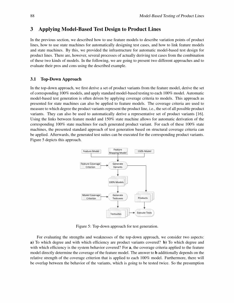
88 Model-Based Testing of Product Lines
3 Applying Model-Based Test Design to Product Lines
In the previous section, we described how to use feature models to describe variation points of productlines, how to use state machines for automatically designing test cases, and how to link feature modelsand state machines. By this, we provided the infrastructure for automatic model-based test design forproduct lines. There are, however, several processes of actually deriving test cases from the combinationof these two kinds of models. In the following, we are going to present two different approaches and toevaluate their pros and cons using the described example.
3.1 Top-Down Approach
In the top-down approach, we first derive a set of product variants from the feature model, derive the setof corresponding 100% models, and apply standard model-based testing to each 100% model. Automaticmodel-based test generation is often driven by applying coverage criteria to models. This approach aspresented for state machines can also be applied to feature models. The coverage criteria are used tomeasure to which degree the product variants represent the product line, i.e., the set of all possible productvariants. They can also be used to automatically derive a representative set of product variants [16].Using the links between feature model and 150% state machine allows for automatic derivation of thecorresponding 100% state machines for each generated product variant. For each of these 100% statemachines, the presented standard approach of test generation based on structural coverage criteria canbe applied. Afterwards, the generated test suites can be executed for the corresponding product variants.Figure 5 depicts this approach.
Feature Model 150% ModelFeature Mapping Model
Generate Variants
Feature Coverage Criterion
100% Models
Generate Testcases
Testsuites
Model Coverage Criterion
Execute Tests
Products
Figure 5: Top-down approach for test generation.
For evaluating the strengths and weaknesses of the top-down approach, we consider two aspects:a) To which degree and with which efficiency are product variants covered? b) To which degree andwith which efficiency is the system behavior covered? For a, the coverage criteria applied to the featuremodel directly determine the coverage of the feature model. The answer to b additionally depends on therelative strength of the coverage criterion that is applied to each 100% model. Furthermore, there willbe overlap between the behavior of the variants, which is going to be tested twice. So the presumption
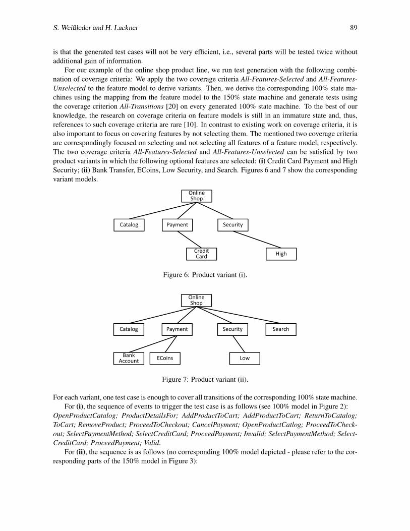
S. Weißleder and H. Lackner 89
is that the generated test cases will not be very efficient, i.e., several parts will be tested twice withoutadditional gain of information.
For our example of the online shop product line, we run test generation with the following combi-nation of coverage criteria: We apply the two coverage criteria All-Features-Selected and All-Features-Unselected to the feature model to derive variants. Then, we derive the corresponding 100% state ma-chines using the mapping from the feature model to the 150% state machine and generate tests usingthe coverage criterion All-Transitions [20] on every generated 100% state machine. To the best of ourknowledge, the research on coverage criteria on feature models is still in an immature state and, thus,references to such coverage criteria are rare [10]. In contrast to existing work on coverage criteria, it isalso important to focus on covering features by not selecting them. The mentioned two coverage criteriaare correspondingly focused on selecting and not selecting all features of a feature model, respectively.The two coverage criteria All-Features-Selected and All-Features-Unselected can be satisfied by twoproduct variants in which the following optional features are selected: (i) Credit Card Payment and HighSecurity; (ii) Bank Transfer, ECoins, Low Security, and Search. Figures 6 and 7 show the correspondingvariant models.
Payment
Online Shop
Catalog
CreditCard
Security
High
Figure 6: Product variant (i).
Payment
Online Shop
Catalog Search
Bank Account ECoins
Security
Low
Figure 7: Product variant (ii).
For each variant, one test case is enough to cover all transitions of the corresponding 100% state machine.For (i), the sequence of events to trigger the test case is as follows (see 100% model in Figure 2):
OpenProductCatalog; ProductDetailsFor; AddProductToCart; AddProductToCart; ReturnToCatalog;ToCart; RemoveProduct; ProceedToCheckout; CancelPayment; OpenProductCatlog; ProceedToCheck-out; SelectPaymentMethod; SelectCreditCard; ProceedPayment; Invalid; SelectPaymentMethod; Select-CreditCard; ProceedPayment; Valid.
For (ii), the sequence is as follows (no corresponding 100% model depicted - please refer to the cor-responding parts of the 150% model in Figure 3):

90 Model-Based Testing of Product Lines
OpenProductCatalog; SearchFor; ProductDetailsFor; AddProductToCart; AddProductToCart; Return-ToSearch; ReturnToCatalog; ToCart; RemoveProduct; ProceedToCheckout; CancelPayment; OpenPro-ductCatalog; ProductDetailsFor; AddProductToCart; ReturnToCatalog; ProceedToCheckout; Select-PaymentMethod; SelectBankAccount; ProceedPayment; Invalid, SelectPaymentMethod; SelectECoins;ProceedPayment; Valid.
All features have been selected as well as deselected. Both test cases together cover all 22 explicitlytriggered transitions of the 150% model. They have a total length of (i:19 + ii:24) 43 event calls, whichis almost twice the size of the lower boundary. Since we created two product variants for testing insteadof the 20 possible ones, however, this approach is still far more efficient than the brute force approach.
Our tool chain that supports the described test generation approach is currently under construc-tion. However, we already manually created the two 100% state machines and used the ConformiqDesigner [5] to automatically design tests. The used coverage criterion is All-Transitions. For varianti, the test generator created seven test cases that comprise altogether 28 event calls. In case of variantii, eleven test cases with 42 event calls were generated. Since the Conformiq Designer is not tailored tofind as many test steps per test case as possible, this deviation from our theoretical considerations are nosurprise. After all, all transitions were covered for both cases.
3.2 Bottom-Up Approach
The idea of the bottom-up approach is contrary to the top-down approach. Here, we create test casesbased on the 150% state machine and match the resulting sequences to single product variants, after-wards. The idea is simple, but the generated paths of the state machine cover elements that are linkedto different features and the state machine does not provide means to check if all these features can becombined in one valid product variant. As a result, one has to include the conditions that are expressed inthe feature model into the 150% state machine. This is done by expressing the selection and deselectionof a feature to a variable with the value 1 and 0, respectively. Figure 8 depicts such an enrichment on
Figure 8: Enriched part of the 150% state machine for automatic test generation of only valid productvariants.
an excerpt of the 150% state machine. The shown composite state was enriched with information fromthe feature model by adding a guard to all transitions leading to the state Search, which corresponds tothe search feature. Now, the tests cover the search function only if the corresponding guard is set totrue. Setting the guard variable to a value is possible only once at the beginning of the state machine.As a consequence, the variable and the feature selection will be consistent for the whole test case. Rela-tions between features can also be expressed in the guard, e.g., by stating that the value of the variablecorresponding to an alternative feature has a different value.
This enables the generator to choose from any valid configuration for finding a new test case. Sincewe did not generate the product variants from the feature model, we had to retrieve the necessary product
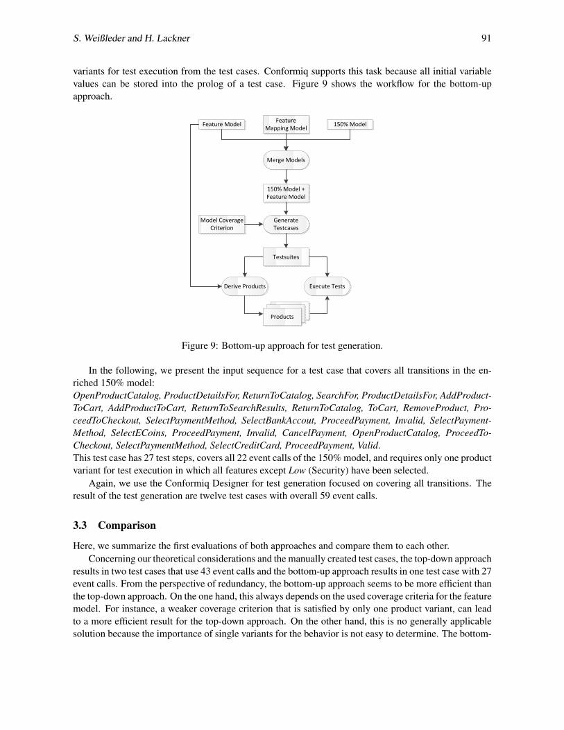
S. Weißleder and H. Lackner 91
variants for test execution from the test cases. Conformiq supports this task because all initial variablevalues can be stored into the prolog of a test case. Figure 9 shows the workflow for the bottom-upapproach.
Feature Model 150% ModelFeature Mapping Model
Generate Testcases
Model Coverage Criterion
Merge Models
150% Model + Feature Model
Derive Products Execute Tests
Testsuites
Products
Figure 9: Bottom-up approach for test generation.
In the following, we present the input sequence for a test case that covers all transitions in the en-riched 150% model:OpenProductCatalog, ProductDetailsFor, ReturnToCatalog, SearchFor, ProductDetailsFor, AddProduct-ToCart, AddProductToCart, ReturnToSearchResults, ReturnToCatalog, ToCart, RemoveProduct, Pro-ceedToCheckout, SelectPaymentMethod, SelectBankAccout, ProceedPayment, Invalid, SelectPayment-Method, SelectECoins, ProceedPayment, Invalid, CancelPayment, OpenProductCatalog, ProceedTo-Checkout, SelectPaymentMethod, SelectCreditCard, ProceedPayment, Valid.This test case has 27 test steps, covers all 22 event calls of the 150% model, and requires only one productvariant for test execution in which all features except Low (Security) have been selected.
Again, we use the Conformiq Designer for test generation focused on covering all transitions. Theresult of the test generation are twelve test cases with overall 59 event calls.
3.3 Comparison
Here, we summarize the first evaluations of both approaches and compare them to each other.Concerning our theoretical considerations and the manually created test cases, the top-down approach
results in two test cases that use 43 event calls and the bottom-up approach results in one test case with 27event calls. From the perspective of redundancy, the bottom-up approach seems to be more efficient thanthe top-down approach. On the one hand, this always depends on the used coverage criteria for the featuremodel. For instance, a weaker coverage criterion that is satisfied by only one product variant, can leadto a more efficient result for the top-down approach. On the other hand, this is no generally applicablesolution because the importance of single variants for the behavior is not easy to determine. The bottom-

92 Model-Based Testing of Product Lines
up approach abstracts from this issue because one does not have to define the coverage criterion on thefeature model in the first place, but it does not necessarily cover all features of the feature model. As aresult, it seems that the personal notion and the importance of the covered aspects is important: If featurecoverage is important, the top-down approach is more suitable. If efficiency and covered behavior ismore important, the bottom-up approach is more suitable.
The application of the Conformiq Designer shows partly similar though different results. For thetwo 100% models, 18 test cases with 70 event calls were generated. For the 150% model, twelve testcases with 59 event calls were generated. The main reason for the deviation to the manually created testcases is the breadth-first search approach of Conformiq and our approach of finding the minimal numberof test cases. Furthermore, the Conformiq Designer created test cases for two product variants for thebottom-up approach. Interestingly, both variants include high security and differ only in the selectionof the feature Credit Card. This distinction is unnecessary and would have been avoided by a humandesigner. This issue leaves room for future improvements.
4 Related Work
In this section, we present the related work. We present standard approaches to model-based testing, citework about feature modeling, and name approaches to combining both.
Testing is one of the most important quality assurance techniques in industry. Since testing oftenconsumes a high percentage of project budget, there are approaches to automate repeating activitieslike, e.g., regression tests. Some of these approaches are data-driven testing, keyword-driven testing, andmodel-based testing. There are many books that provide surveys of conventional standard testing [1,2,12]and model-based testing [3,20,25]. In this paper, we use model-based testing techniques and apply themto product lines. Modeling languages like the Unified Modeling Language (UML) [13] have been oftenused to create test models for testing. For instance, Abdurazik and Offutt [14] automatically generatetest cases from state machines. We also apply state machines of the UML.
Feature models are commonly used to describe the variation points in product lines. There are severalapproaches to apply feature models in quality assurance. For instance, Olimpiew and Gomaa [15] dealwith test generation from product lines and sequence diagrams. In contrast to that, we focus on UMLstate machines and describe different approaches for combining both. In contrast to sequence diagrams,state machines are commonly used to describe a higher number of possible behaviors, which make thecombination with feature models more complex than combining feature models and sequence diagrams.As another example, McGregor [11] shows the importance of a well-defined testing software product lineprocess. Just like McGregor, the focus of our paper is only investigating the process of actually creatingtests rather than defining the structural possible relations of feature models and state machines. Pohl andMetzger [17] emphasize the preservation of variability in test artifacts of software product line testing. Aswe derive test case design from models automatically, this variability is preserved. Lochau et al. [10] alsofocus on test design with feature models. In contrast to our work, they focus on defining and evaluatingcoverage criteria that can be applied to feature models. In the presented top-down approach, we strivefor using such coverage criteria on feature models for the automation of test design. Cichos et al. [4] alsoworked on an approach similar to the presented bottom-up approach. Their approach, however, requiresthat the used test generator has to be provided a set of product variants to derive 100% models from the150% model for automatic test generation. As a consequence, the test generator requires an additionalinput parameter and (as the authors state) no standard test generator can be applied for their approach.In contrast, both of our approaches allow for integrating commercial off-the-shelf test generators like in

S. Weißleder and H. Lackner 93
our case, Conformiq [5]. One of the most important aspects in our work is the ability to integrate ourapproach into existing tool chains. In [23], we already addressed model-based test generation for productlines. However, back then we focused on reusing state machines in multi-variant environments insteadof describing the different automatic test design approaches for product lines.
5 Summary, Discussion, and Future Work
In this paper, we presented different approaches to the automatic test design for product lines. Wedescribed the state of the art, presented the general idea of linking feature models to other system artifacts,and presented two approaches to use this linking for automatic test design. Our main contributions arethe definition and comparison of the presented approaches using a small example.
The presented outcomes are theoretical considerations and first test generation results using the Con-formiq Designer. Some steps of the proposed tool chains are still under construction and the correspond-ing intermediate results were, thus, partly created manually. If the missing parts of the tool chains willbe developed, we will be able to run larger case studies for the comparison of both approaches automat-ically. Furthermore, there are more approaches than the presented ones of automatically designing testsfor product lines that were not evaluated here. To name just one example, single steps in our automatictool chain could also be replaced by manual experience-based steps. Another point to discuss is thedegree of reusability in the source code. As mentioned in the beginning of this paper, reusing systemcomponents is an important aspect in managing product variants engineering for product lines. If thecomponents, however, were not reused adequately and copy&paste was applied, instead, then coveringthe behavior at the source code level for one product variant does not necessarily imply covering the verysame behavior at the source code level for another product variant. A solution to this issue would be toalso integrate the relations from features in the feature model to variation points in the source code.
In the near future, we plan to finish the development of both proposed tool chains. The tool chains areintended to provide the glue between existing tools for feature modeling like, e.g., pure::variants [18] orthe FeatureMapper [7], and automatic test generators like, e.g., the Conformiq Designer [5] or ParTeG [22].Besides the comparison of the two approaches, the single approaches contain enough room for furtherinvestigations. For instance, one interesting question for the top-down approach is if it is advisable toapply strong coverage criteria on the feature model and weak ones on the 100% models or vice versa.For the bottom-up approach, an interesting task is to retrieve a minimal number of product variants fromtest cases generated from the 150% model. As stated above, we also plan to run further experiments toevaluate the pros and cons of the presented approaches.
References
[1] Paul Ammann & Jeff Offutt (2008): Introduction to Software Testing. Cambridge University Press, NewYork, NY, USA, doi:10.1017/CBO9780511809163.
[2] Robert V. Binder (1999): Testing Object-Oriented Systems: Models, Patterns, and Tools. Addison-WesleyLongman Publishing Co., Inc., Boston, MA, USA.
[3] Manfred Broy, Bengt Jonsson & Joost P. Katoen (2005): Model-Based Testing of Reactive Systems: AdvancedLectures (Lecture Notes in Computer Science). Springer, doi:10.1007/b137241.
[4] H. Cichos, S. Oster, M. Lochau & A. Schurr (2011): Model-based Coverage-Driven Test Suite Generation forSoftware Product Lines. In: Proceedings of the ACM/IEEE 14th International Conference on Model Driven

94 Model-Based Testing of Product Lines
Engineering Languages and Systems, Lecture Notes in Computer Science (LNCS) 6981, Springer Verlag,Heidelberg, pp. 425–439, doi:10.1007/978-3-642-24485-8 31.
[5] Conformiq: Designer 4.4. http://www.conformiq.com/.[6] Inc. Forrester Research (2012): The Total Economic Impact of Conformiq Tool Suite.
http://www.conformiq.com/tei-conformiq.pdf.[7] Florian Heidenreich (2012): FeatureMapper. http://featuremapper.org/.[8] IBM: Rational DOORS. www.ibm.com/software/products/us/en/ratidoor.[9] Hartmut Lackner, Jaroslav Svacina, Stephan Weißleder, Mirko Aigner & Marina Kresse (2010): Introducing
Model-Based Testing in Industrial Context - An Experience Report. In: MoTiP’10: Workshop on Model-Based Testing in Practice.
[10] Malte Lochau, Sebastian Oster, Ursula Goltz & Andy Schurr (2012): Model-based pairwise testing for fea-ture interaction coverage in software product line engineering. Software Quality Journal 20(3-4), pp. 567–604, doi:10.1007/s11219-011-9165-4.
[11] John D. McGregor (2001): Testing a Software Product Line. Technical Report CMU/SEI-2001-TR-022.[12] Glenford J. Myers (1979): Art of Software Testing. John Wiley & Sons, Inc., New York, NY, USA.[13] Object Management Group (2011): Unified Modeling Language (UML), version 2.4. http://www.uml.
org.[14] Jeff Offutt & Aynur Abdurazik (1999): Generating Tests from UML Specifications. In Robert France &
Bernhard Rumpe, editors: UML’99 - The Unified Modeling Language. Beyond the Standard. Second Interna-tional Conference, Fort Collins, CO, USA, October 28-30. 1999, Proceedings, 1723, Springer, pp. 416–429,doi:10.1007/3-540-46852-8 30.
[15] Erika Mir Olimpiew & Hassan Gomaa (2005): Model-Based Testing for Applications Derived from SoftwareProduct Lines. ACM SIGSOFT Software Engineering Notes 30(4), pp. 1–7, doi:10.1145/1082983.1083279.
[16] Sebastian Oster, Ivan Zorcic, Florian Markert & Malte Lochau (2011): MoSo-PoLiTe: tool support forpairwise and model-based software product line testing. In: VaMoS, pp. 79–82. Available at http://doi.acm.org/10.1145/1944892.1944901.
[17] Klaus Pohl & Andreas Metzger (2006): Software Product Line Testing. Communications of the ACM 49(12),pp. 78–81, doi:10.1145/1183236.1183271.
[18] pure systems (2012): pure::variants. http://www.pure-systems.com.[19] Carnegie Mellon University (2012): Software Product Lines. http://www.sei.cmu.edu/
productlines/.[20] Mark Utting & Bruno Legeard (2006): Practical Model-Based Testing: A Tools Approach. Morgan Kauf-
mann Publishers Inc., San Francisco, CA, USA.[21] Mark Utting, Alexander Pretschner & Bruno Legeard (2012): A Taxonomy of Model-Based Testing Ap-
proaches. Softw. Test. Verif. Reliab. 22(5), pp. 297–312, doi:10.1002/stvr.456.[22] Stephan Weißleder: ParTeG (Partition Test Generator). http://parteg.sourceforge.net.[23] Stephan Weißleder, Dehla Sokenou & Holger Schlingloff (2008): Reusing State Machines for Automatic Test
Generation in Product Lines. In Axel Rennoch Thomas Bauer, Hajo Eichler, editor: Model-Based Testing inPractice (MoTiP), Fraunhofer IRB Verlag.
[24] Stephan Weileder & Hartmut Lackner (2010): System Models vs. Test Models -Distinguishing the Undis-tinguishable? In Klaus-Peter Fhnrich & Bogdan Franczyk, editors: GI Jahrestagung (2), LNI 176, GI, pp.321–326. Available at http://dblp.uni-trier.de/db/conf/gi/gi2010-2.html#WeisslederL10.
[25] Editors Justyna Zander, Ina Schieferdecker & Pieter J. Mosterman (2011): Model-Based Testing for Embed-ded Systems. CRC Press.


