202
Proceedin~s .of the 16-1~ January 1986 DARPA Gateway Algorithms and Data Structures Task Force ~

Proceedin~s .of the16-1~ January 1986
DARPAGateway Algorithms and Data Structures
Task Force ~

TABLE OF CONTENTS
Minutes of the Fourth DARPA GADS Task Force Meeting
APPENDIX A Hardcopy of GADS Presentation Slides
Page1
13
APPENDIX B Papers Distributed at GADS Meeting 125

Minutes of the Fourth DARPA GADS Task Force Meeting
Minutes of theFourth
DARPA Gateway Algorithms and Data StructuresTask Force Meeting
16-17 January 1986
Prepared by
Phillip GrossMitre Corporation
Gateway Algorithms Task Force
Table of Contents
1. Introduction
2. Attendees ....................................................................................................................................
2.1 Members in Attendance (16) .....................................................................................................
2.2 Additional Attendees (5) ...........................................................................................................
3. Meeting Notes
3.1 16 January 1986 ....................................................................................................................3.2 17 January 1986
4. Addenda
4.1 Distributed Agenda ...................................................................................................................
4.2 Reference Documents for this Meeting ......................................................................................
4.3 Proposed Charter of the Internet Architecture Task Force (INARC) ........................................4.4 Proposed Charter of the Internet Engineering Task Force (IETF) .............................................
-i-
1. Introduction
The fourth meeting of the DARPA Gateway Algorithms and Data Structures Task Force was held 16-17January 1986 at M/A Com Government Systems in San Diego, California. The meeting was hosted byDavid Mills.
Acknowledgments: Thanks to Noel Chiappa, Zaw-Sing Su, and Carl Rokitanski, who responded torequests for information with very helpful comments. Profuse thanks to Pat Keryeski, who performed theonerous task of editing these minutes and compiling the Proceedings.
Gateway Algorithms Task Force
2. Attendees
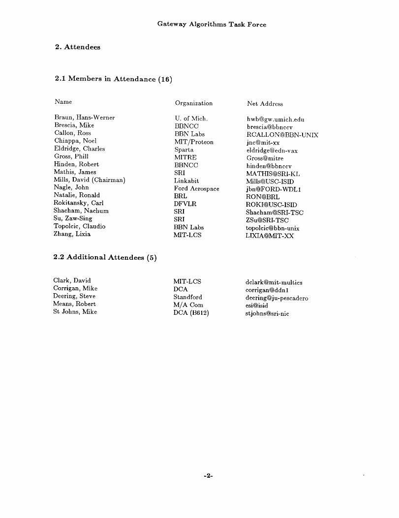
2.1 Members in Attendance (16)
Name
Braun, Hans-WernerBrescia, MikeCallon, RossChiappa, NoelEldridge, CharlesGross, PhillHinden, RobertMathis, JamesMills, David (Chairman)Nagle, JohnNatalie, RonaldRokitansky, CarlShacham, NachumSu, Zaw-SingTopolcic, ClaudioZhang, Lixia
Organization
U. of Mich.BBNCCBBN LabsMIT/ProteonSpartaMITREBBNCCSRILinkabitFord AerospaceBRLDFVLRSRISRIBBN LabsMIT-LCS
Net Address
[email protected]@bbnccvRCALLON@BBN-UNIXjnc@mit-xxeldridge@edn-vaxGross@mitrehinden@bbnccvMATHIS@SRI-KLMills@USC-ISIDjbn@FORD-WDL1RON@BRLROKI@USC-ISIDShacham@SRI-TSCZSu@SRI-TSCtopolcic@bbn-unixLIXIA@MIT-XX
2.2 Additional Attendees (5)
Clark, DavidCorrigan, MikeDeering, SteveMeans, RobertSt Johns, Mike
MIT-LCSDCAStand fordM/A ComDCA (B612)
dclark@mit-multicscorrigan@ddnldeering@ju-pescaderoesi@isidstjohns@sri-nic
-2-
Gateway Algorithms Task Force
3. Meeting Notes
3.1 16 January 1986
The Chair opened the meeting by announcing that the agenda had been substantially changed by recentevents. The most important being the eminent demise of the Gateway Algorithm and Data StructuresTask Force (GADS) and the formation of two new task forces in its place: the Internet Engineering TaskForce (INARC) and the Internet Architecture Task Force (IETF). The INARC will focus on long research issues and will continue to be chaired by Dave Mills. The IETF will concentrate on short termoperational problems and will be chaired by Mike Corrigan. Proposed charters for these new groups areincluded with these minutes.
Further, the proposed joint meeting that will meet in the afternoon with the National Science Foundation(NSF) subcommittee (on interconnectivity for supercomputer networks), needed to be restricted due space limitations. Therefore, it was proposed that Mike Corrigan chair the first session of the IE~TF thatafternoon.
The remainder of the morning was spent listening to brief status reports and discussing various issues.The following paragraphs contain the highlights.
1) Hinden announced that some Butterflys would be installed by 1 March. Since a Butterfly should beable to handle up to 1000 networks, work being done on the LSI gateways (to allow the Butterflys tohandle up to 300 networks) should be complete within six months. Hinden also distributed the latestInternet-on-a-chip graphic.
2) Nagle had been evaluating commercially available gateways and gave interesting comments on several.He also commented on the Multinet gateway, calling it a "gateway to provide isolation". His work oncongestion control in gateways and a gateway database protocol will be reported in detail later in themeeting.
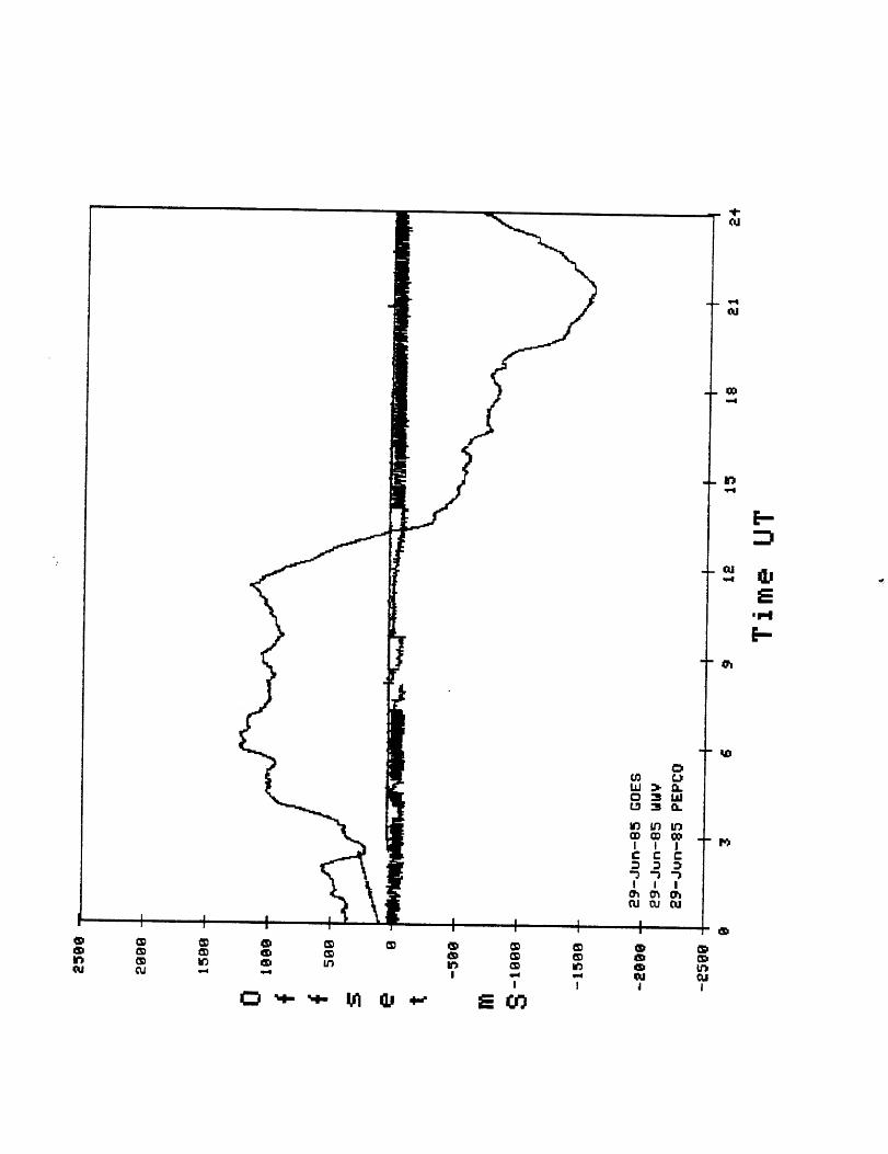
3) Mills discussed several papers on a new service enhanced model for the Internet: AutonomousConfederations and the Network Time Protocol.
4) Clark was very concerned with recent ISO developments. He gave his "seven year wave and troughcycle" analysis, in which three year waves of research were followed by four or more years of integrationof that research into operational products. He suggested that ISO lived in the calmer seas of the trough.He distributed copies of the proposed Host-Gateway Protocol (or, in ISO parlance, End System toIntermediate System Routing Protocol) and planned to discuss it in detail on the following day. Headvocated the switching of ISO Internet Protocol (IP) datagrams in the Internet gateways. This led Millsto suggest that a proposal for mapping Internet addressing onto the ISO scheme was needed. Callonvolunteered to present a possible arrangement on the following day.
In the afternoon (while the Chair and several members attended the NSF Gateway Subcommittee)Corrigan chaired, what amounted to as, the initial IETF meeting.
Although there were numerous topics of immediate operational concern (Subnets, routing in the host IPlayer, EGP, and switching ISO datagrams were all mentioned in an opening discussion), Corrigan focused
-3-

Gateway Algorithms Task Force
the discussion on the following areas:
IETF Areas of Concern -
o Protocol Development and Stabilization,
o Protocol Conformance,
o An Implementors Support Organization,
o Internet Performance Measurements,
o ISO Conversion.
The remainder of the afternoon consisted primarily of an organizational brainstorming session (of IETFAreas of Concern) by members who produced the following three groups of topics:
Protocol Development and Stabilization -
1) Immediate Concerns (three months- one year):o EGP Improvements,o EGP Table Control,o Specification of Host IP Requirements including:
- Multi-Homed Hosts- Subnets
o IP Implementation Guidelines for Congestion Avoidance,o TCP Specification Update,o Host Interface Specification.
2) Intermediate Concerns (one year - three years):o Improved Internet Performance (one order of magnitude),o EGP Replacement,o Gateway Load Sharing,o Internet Access Control and Authentication (liaise with Privacy TF),o Protocol Requirements for Transportable Hosts,o Name/Address Service,o Name/Address Convergence with ISO.
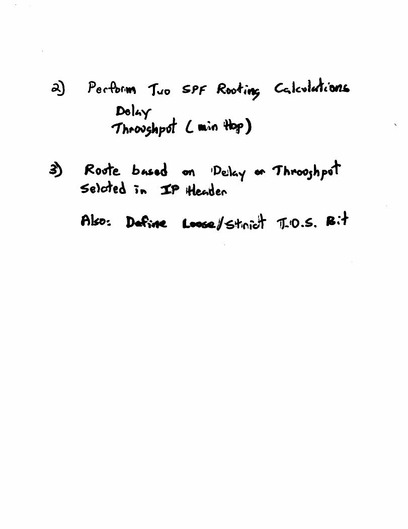
3) Longer Term Concerns (three years- seven years):o Improved Internet Performance (two to three orders of magnitude),o Large Scale Internet Routing including:
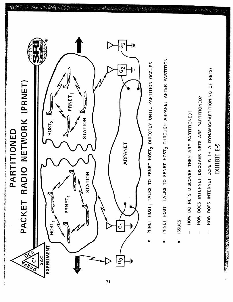
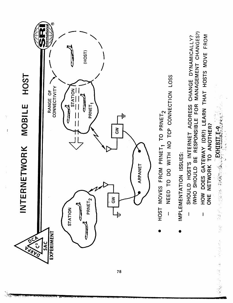
- Partitioned Network Support- Multi-Path Routing- Type-Of-Service Routing- Mobile Hosts
o Real Congestion Control,o Logical Internet Addressing,o IP Multi-Cast Addressing.
The most pressing topics of immediate concern listed above fall into two broad categories: EGPmodifications and IP implementation guidance. It is proposed that these topics become the focus of thenext IETF meeting, which has been scheduled for 8-9 April 1986 at the Ballistic Research Laboratory(BRL) in Aberdeen, Maryland.
A more detailed version of these notes has been distributed with the agenda of the 8-9 April meeting tomembers of both new task forces.
-4-

Gateway Algorithms Task Force
3.2 17 January 1986
The second day of the meeting was composed primarily of technical presentations.
Eldridge gave a status report of Sparta’s ongoing work for DCA. The five principle tasks are:
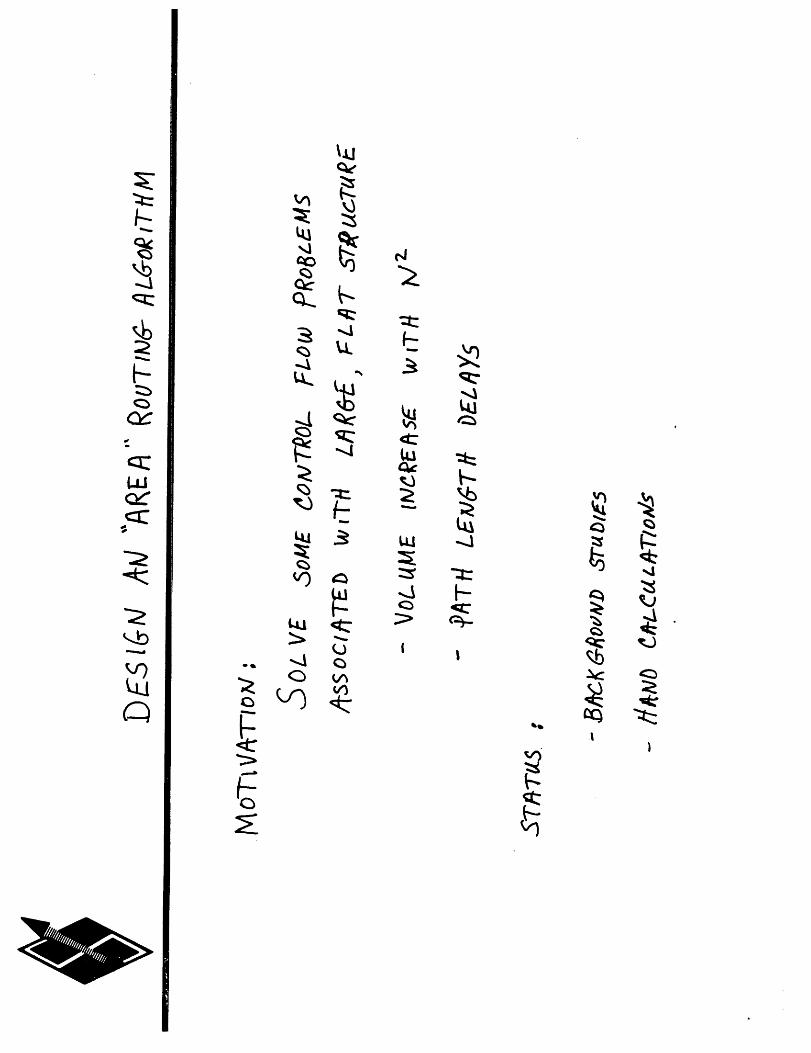
- Design an area routing algorithm,
- Develop gateway functional requirements,
- Describe architecture of the next generation packet switch,
- Identify improved network feedback to hosts, and
- Protocol certification support.
He then presented an Application of Multi-Objective Optimization to Networking by C. Eldridge. Shachamwas able to provide additional references for the work.
Nagle presented his "Gateway Database Protocol", which he developed for the Multinet SurvivableInternet Routing Program. In this work, he distinguishes between the routing and distributed databaseproblems, which together make up Internet routing. He presented several interesting innovations, one ofwhich was that his protocol runs above a reliable transport service. He distributed a paper whichdocumented the protocol.
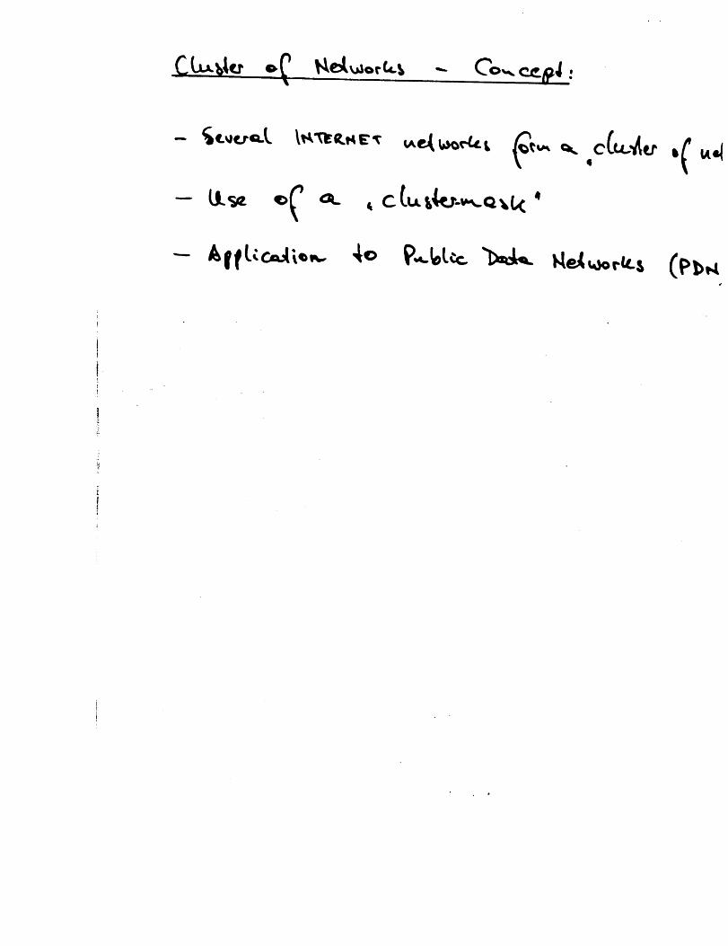
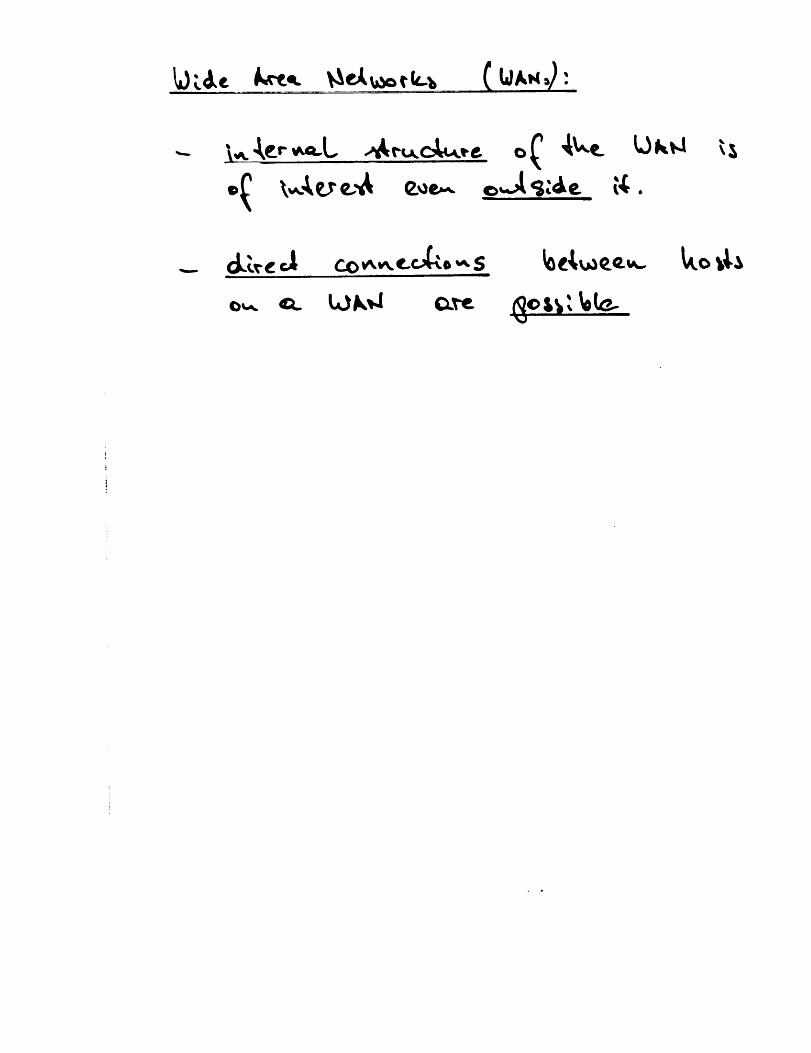
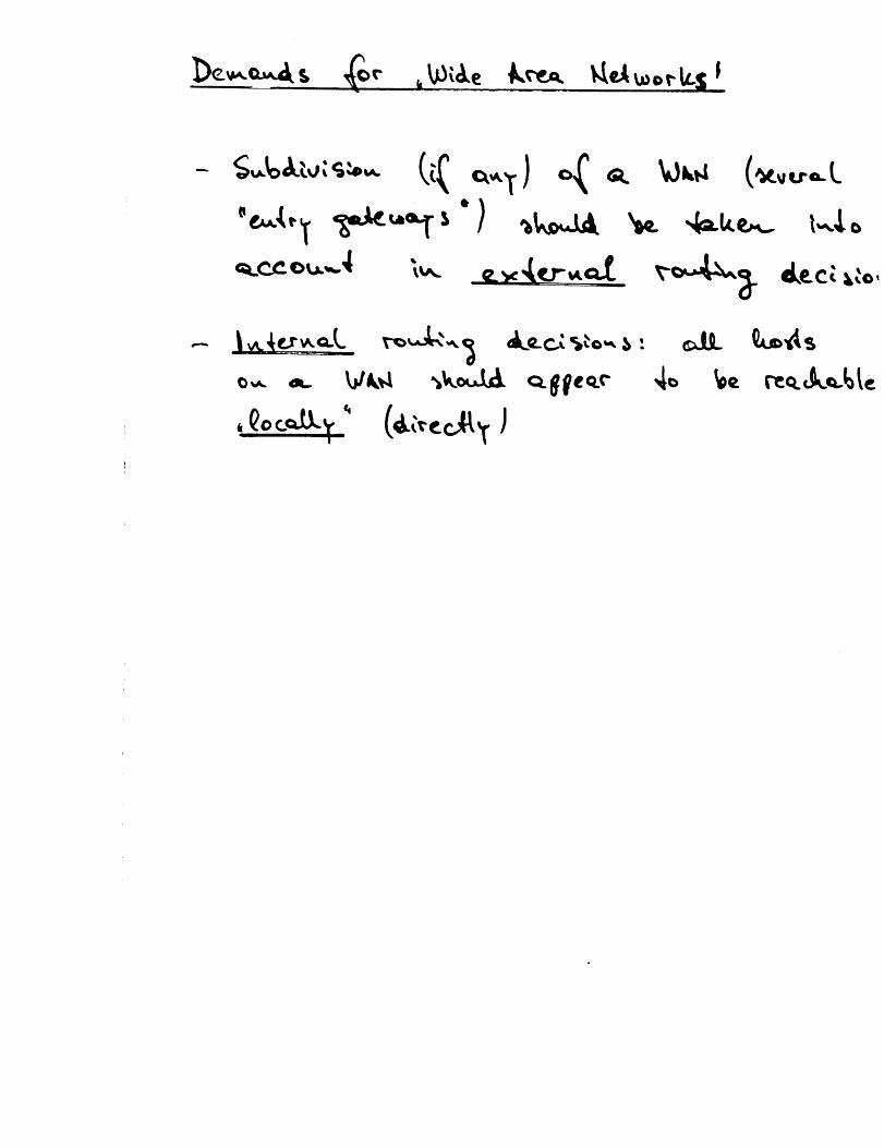
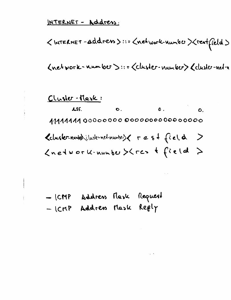
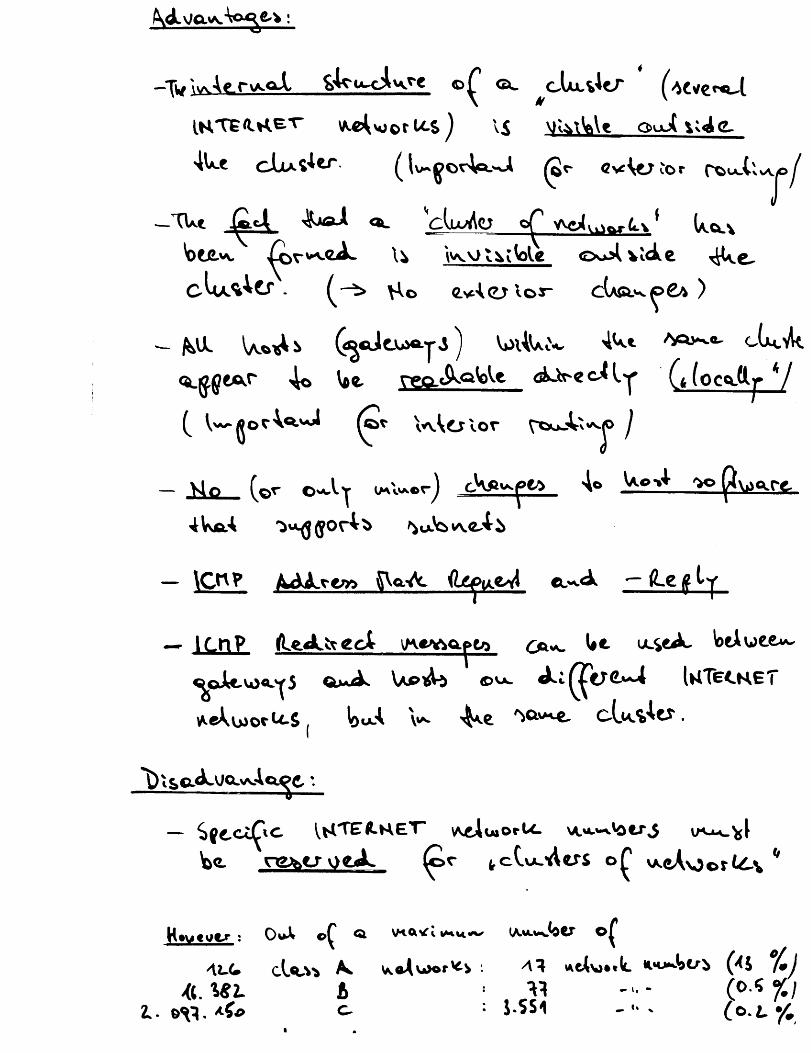
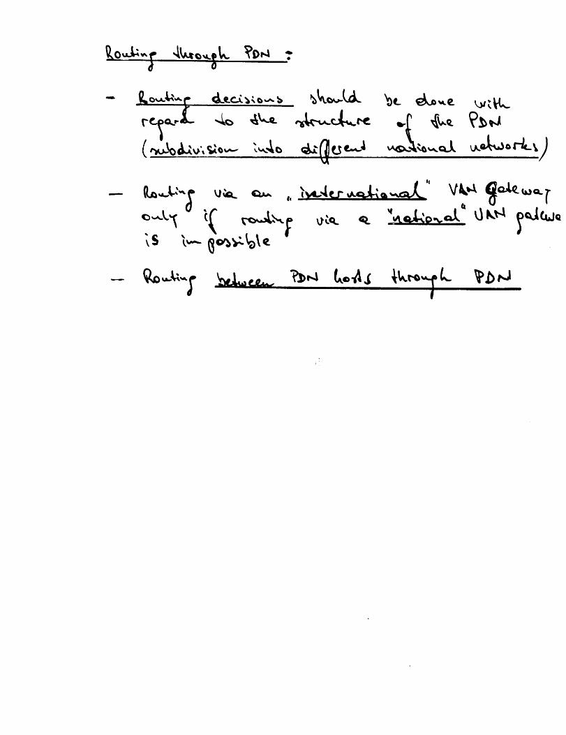
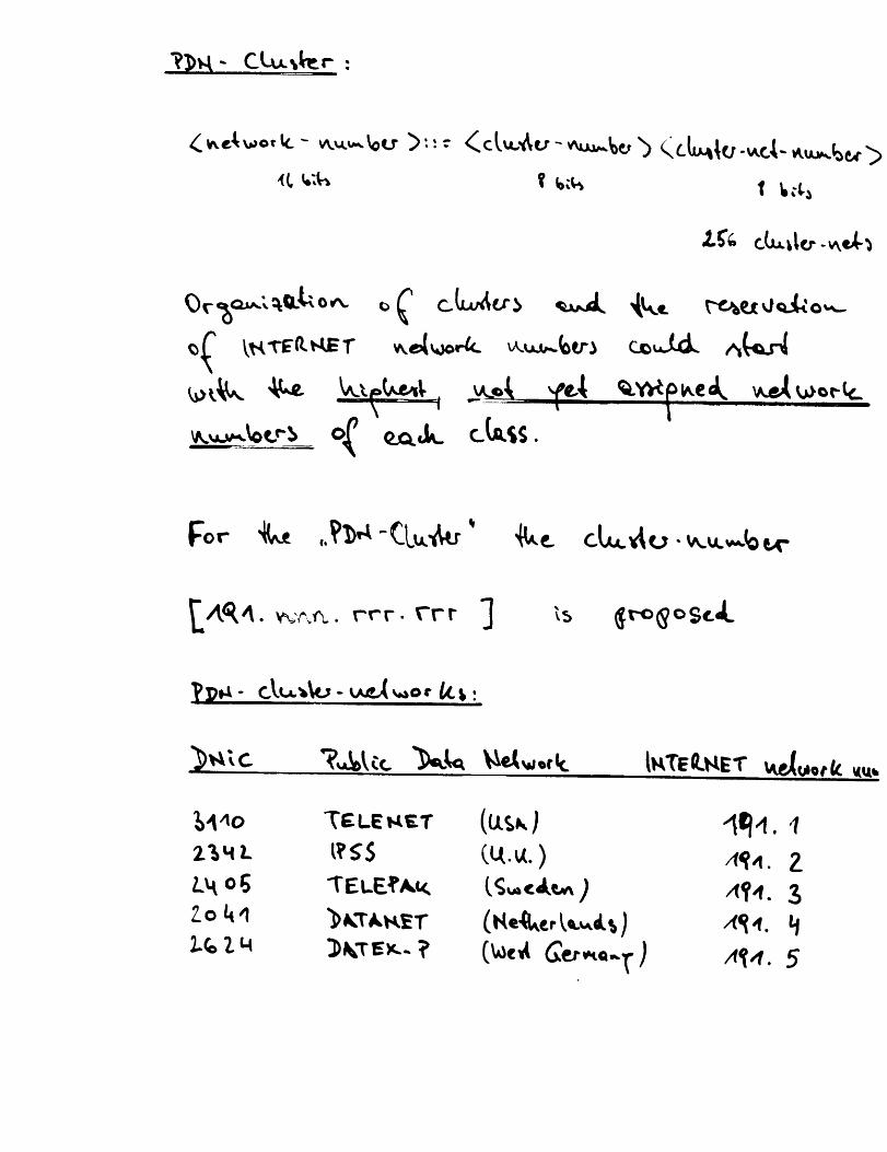
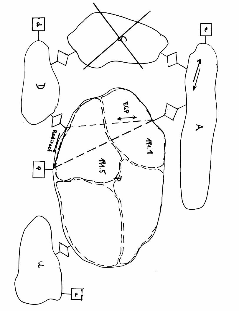
Roki presented the main points of his paper, Clusters of Networks - Application to Public Data Networks(PDN). His proposal would allow Internet hosts with PDN connectivity to route to other PDN hostsdirectly (even to those on different Internet networks) without using an Internet gateway. Traffic betweensuch Internet/PDN hosts would be preferentially routed through the PDN. Roki’s scheme involvesassociating a set of Internet networks to a "cluster of networks" and then using a "cluster-mask",analogous to the subnet address mask scheme, for routing decisions.
Mills elaborated on two papers that he distributed since the last meeting. They were his "wiretap"routing algorithm, developed during work on the amateur packet radio network, and A New Enhanced-Service Model for the Internet. Mills was particularly interested in drawing parallels between his work,Roki’s clustering scheme, and Su’s work on gateway "affiliations".
Nagle presented his "fair queuing" scheme, in which gateways maintain separate queues for each sendinghost. In this way, hosts with pathological implementations can not usurp more than their fair share of thegateway’s resources. This invoked spirited and interested discussion. Zhang pointed out that this was asubtle change in architecture away from a pure datagram network. Callon reminded everyone that hehad written a paper advocating a connection oriented Internet Protocol several years ago.
Deering presented his work, Host Groups: A Multicast Extension for Datagram Internetworks. Hepersuasively argued in favor of multicasting and gave arguments against broadcasting schemes. He hopedthat the Task Force could:
provide some critical comments on the proposal,
- consider multicast in design of next generation protocols (e.g., routing),
- discourage proliferation of broadcast based protocols, like ARP.
-5-
Gateway Algorithms Task Force
Clark discussed ~he proposed ISO Hos~-Ga~eway Protocol. He was concerned wi~h several aspects of ~heprotocol, such as i~s restriction ~o specific network ~opologies. This re-opened a wider discussion on ISOissues, in which Mills again suggested ~ha~ In~erne~ gateways should switch ISO da~agrams. Callonpresented his suggestion for "Al~PA-In~erne~ Use of OSI NSAP Addressing". Mills suggested ~ha~ ~hisproposal be documented as a l~eques~ for Commen~s (I~FC).
Hardcopys of slides and/or position papers are available for each of ~he above presentations. They arecompiled wi~h these minu~es for distribution.
-6-

Gateway Algorithms Task Force
4. Addenda
4.1 Distributed Agenda
As distributed by the Chair prior to the meeting:
Thursday, 16 January
0900-09300930-10301030-1200
1200-13001300-1700
Friday, 17 January
0900-1200
1200-13001300-1700
Welcome and admonishmentOld business and action itemsStatus reportsCook: Multinet GatewayHinden and Seamonson: Butterfly GatewayNatalie and Chiappa: other gatewaysMathis and Su: reconstitution demonstrationsMills: time-synchronization protocols and experimentsNew players: CNUCE Italy (Erina Ferro), U. Michigan
(Hans-Werner Braun), NBS (Steve Ritzman)Guest players: DDN PM (Mike St. Johns), Linkabit (ESI crew)LunchJoint meeting with NSF Supercomputer Gateway CommitteeClark: tutorial on DoD Internet architectureMills: tutorial on Internet gateway systems and issues
Documented presentationsEldridge: gateway studies and issues (see sparta.doc)Nagle: an open architecture for routing (document to be
supplied)Mills: new internet models (see newmod.doc)Clark: the ISO view on IC1V[P (document to be supplied)Rokitanski: cluster of networks (see roki.msg)LunchDiscussionMills and Su: autonomous systems and confederations (see
updated confed.doc)Nagle and Zhang: congestion-control issues and gateway
design (see RFC960)Callon, Hinden and Brescia: issues on the conversion of the
Internet gateway system to switch ISOgrams, especiallyaddress mappings
Ritzman and Gross: issues on gateway architecture and routingstandards
Clark, Shacham, Cohen, and Mills: action items for futureresearch
-7-

Gateway Algorithms Task Force
4.2 Reference Documents for this Meeting
Important files on dcn9 in/usr/ftp/pub/gads:
gadsl.msggads2.msggads3.msg
Mailbags of messages since inception of GADS.
gadsm.msg Minutes of previous GADS meetings.
jbnl.msg Note on congestion-control mechanisms for gateways, by JohnNagle.
roki.msg An opus on addressing issues in public data nets, by C-H(Roki) Rokitanski.
sparta.doc An opus on gateway issues by our Spartan friends.
egpl.msg Exchange of messages on standards issues and EGP.
egp2.msg Exchange of messages on other EGP issues.
rfc904.txt Current revision of the EGP specification document. Unchangedsince last posting before the last meeting.
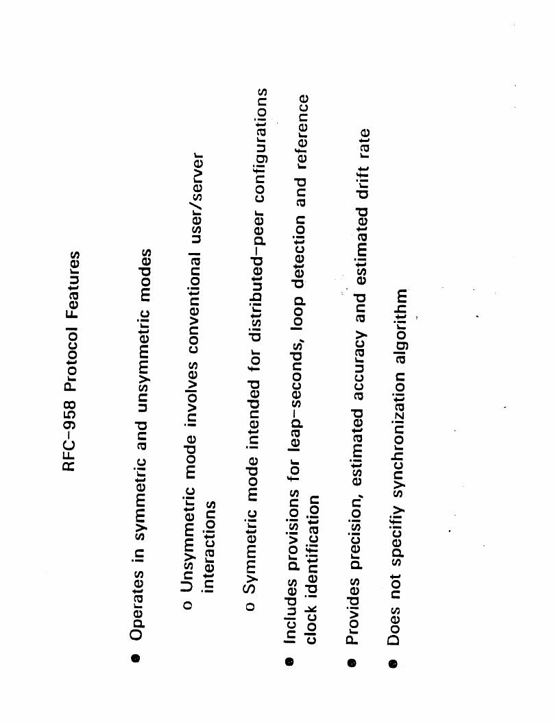
r~958.doc Current revision of Mill’s NTP specification document. Revisedand expanded since last posting, before the last meeting as thefile TIMPRO.TXT on usc-isid.arpa. Note that the other files ontime-synchronization algorithms and experiments have sinceappeared as RFC956 and RFC957.
wirtap.doc Current revision of Mill’s document on "wiretap" algorithms,originally written for another readership, but containing aninteresting multiple-path routing algorithm.
newmod.doc Current revision of Mill’s document proposinga new engineering model for the Internet, in RFC format.
confed.doc Extensively updated revision of Mill’s document on AutonomousConfederations, in RFC format.
See also:
hardcopy Zakon, S., An architecture for routing in the ISOconnectionless Internet, ACM Computer Communications Review,October/November 1985, pages 10-39.
RFC956, RFC957, and RFC958 on time synchronization, RFC970on gateway congestion, RFC966 on multicasting/host groups,RFC963/RFC964 on problems with the IP/TCP specs.
-8-
Gateway Algorithms Task Force
4.3 Proposed Charter of the Internet Architecture Task Force (INARC)
The mission of this task force is to explore and extend the architectures and engineering models forinternet systems, in general, and the DoD Internet, in particular. The goal of the effort is to provide asound infrastructure for new services and applications being developed by other task forces, in particularthe End-to-End and Applications task forces. Primary emphasis is placed on research issues leading tonear-term prototype testing and evaluation in the context of these new services and applications; however,strong emphasis is also placed on general internet research issues and in collaborating with other taskforces on these issues.
The products of this task force are expected to be in the form of technical memoranda and otherdocuments useful in the advanced planning and evaluation cycle (as well as briefings as appropriate). Thetask force will also serve as a source of advice and coordination on network experiments and performanceevaluation, as well as to serve as an advisor on advanced planning for the operational agencies and usergroups.
4.4 Proposed Charter of the Internet Engineering Task Force (IETF)
The mission of this task force is to identify and resolve engineering issues in the near-term planning andoperation of the DoD Internet. The goal of the effort is to improve and expand the service for operationalusers, including the gateway system and various networks operated (on behalf of all users such as Arpanetand Milnet). Primary emphasis is placed on growth forecast, problem identification, and solutionspecification. Since solutions are expected to be effected by contractors, emphasis is also placed on adviceto contractors and review of performance. Strong emphasis is also placed on near-term planning forgrowth in system size and improvement in performance.
The products of this task force are expected to be in the form of technical memoranda and otherdocuments useful to the operational agencies and their contractors. It is expected that much of theagenda of this task force will be created by these agencies and the users. However, this task force is notintended as a forum for discussion of policy issues on administration or procurement.
-9-

APPENDIX A
Hardcopy of GADS Presentation Slides
Author Title
C. Eldridge
J. Nagle
C. H. Rokitansky
D. Mills
D. Mills
J. Nagle
D. Cheriton~ S. Deering
R. Callon
B. Hinden
Application of Multi-Objective Optimization to Networking
A New Internet Routing Protocol
Cluster of Networks
The Wiretap Algorithm
Network Time Protocol (NTP)
Congestion in the Internet Doing Something About It
Host Groups: A Multicast Extension for Datagram Internetworks
Arpa-Internet Use of OSI NSAP Addressing
Type of Service Routing (not presented at meeting)

Application
Networkingof Mul ti-Objective Optimization to
Motivations
A new theory emerging from classical Operations Research
approaches
Hope to illuminate problems, find solutions in
(inter)networking
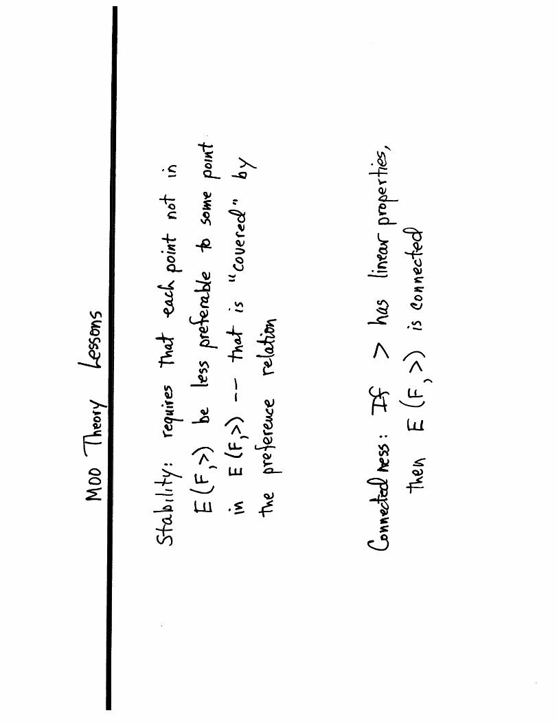
Conclusions
New theory has developed a framework, but
We’ll still explore via implementations and simulations.

Reference: Y. Sawarai, H. Nakayama and T.
Tanino, Theory of Multiobjective Optimization
(Academic Press). Mathematics in Science andEngineering, Vol. 176.

o£


Impact Model
Structural Model does/need not produce
deterministic results; instead weobtain parameters of distributions.
Particularly true in internetworkin¢,
where structural model is queueing
system.
Decision-maker must choose among risky
alternatives: HOW? Via a suitableutility thoery.
Example: Lottery A = [3000:1.00],
Lottery B=[4000,0:0.80, 0.20]; Most
prefer Lottery A. Yet, if Lottery C
= [3000,0:0.25, 0.75] while LotteryD- [4000,0:0.20,0.80], most perfer
D.

Impact Model
von Neumann-Morgenstern utility theory
is classical starting point; is based
on expected value.
other factors enter in, especially risk
aversion;
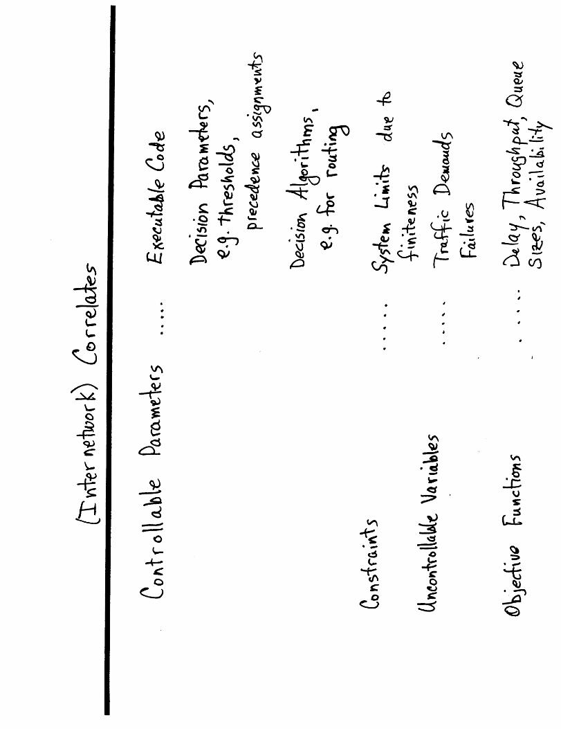
Internetworking correlates include
probability distributions of delays,
throughput, frequency of packet loss;
Internetworking’s Impact Model isApplica tion-Dependent
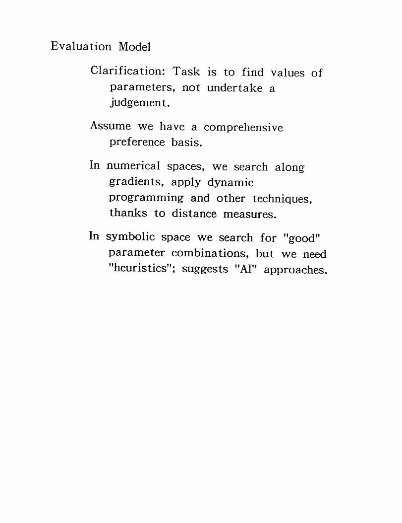
Evaluation Model
Clarification: Task is to find values ofparameters, not undertake a
judgement.
Assume we have a comprehensive
preference basis.
In numerical spaces, we search along
gradients, apply dynamic
programminff and other techniques,
thanks to distance measures.
In symbolic space we search for "~ood"
parameter combinations, but we need"heuristics"-, su~gests "AI" approaches.

SO WHAT?
Internetworking’s "structure model" isvery complex; interdependencies in
time and space abound; comparable
to macroeconomic models;
Models (of the Internet and othersystems) usually oversimplify
anyway; gain from trying to apply
MOO theory is uncertain;
In particular, optimization techniques
depend heavily upon parameterization
into Euclidean space, rendering
controls into "knobs" and "dials."
Internetworking likely to continue asempirical science: design, build,
simulate, experiment, analyze,
uncover principles.


1/14/86JBN
FOIL 1
A New Internet Routing Protocol
John Nagle
Ford Aerospaceand Communications Corporation

1/14/86JBN
FOIL 2
EGP has got to go¯ Nobody likes EGP, it’s just been available.
¯ It was never intended as a real routing protocol.

1/14/86JBN
FOIL 3
GGP has reached its limits¯ We’re nearing table size limits now.
¯ GGP generates N**2 traffic, at non-trivial levels.
¯ Any "core" gateway can kill the GGP system,and not all "core" gateways are in securedfacilities. And they can’t be, or the ARPANETwon’t work.

1/14/86JBN
FOIL 4
Survivable internet Routing Program¯ "If there’s a way to get there, find it and use it."
¯ May route into and through other nets andinternets.
¯ Must be robust in face of disruption, accidentalor deliberate.

1114/86JBN
FOIL 5
Gateway Database Protocol¯ Designed for S IRP program, but of more general
utility.
¯ Still in preliminary form, offered here forcomments.
¯ A candidate as an EGP and GGP replacement.
1/14/86JBN
FOIL 6
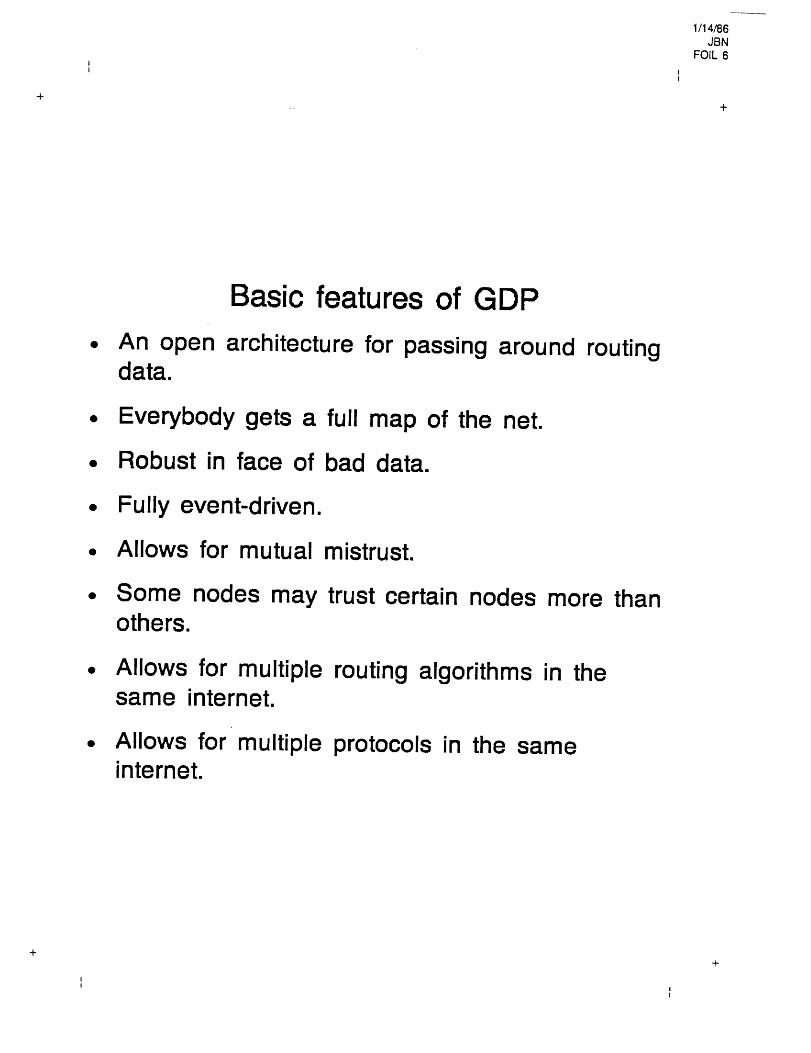
Basic features of GDP¯ An open architecture for passing
data.around routing
¯ Everybody gets a full map of the net.
¯ Robust in face of bad data.
¯ Fully event-driven.
¯ Allows for mutual mistrust.
¯ Some nodes may trust certain nodes more thanothers.
Allows for multiple routing algorithms in thesame internet.
¯ Allows for multiple protocols in theinternet.
same

1/14/86JBN
FOIL 7II
Architecture¯ Every node has a few neighbors that it talks to
on a continuing basis, just like EGP, GGP, etc.
¯ Nodes establish transport connections to peersto exchange routing data.
¯ GDP thus requires a transport protocolunderneath. This gets checksums, sequencing,3-way handshakes, timers, acknowledges, etc.out of the routing protocol. Simplifies the wholething enormously.
¯ Any transport protocol will do, but TCP isrecommended in IP nets and TP4 in ISO nets.
The protocol basically defines a way ofsynchronizing a replicated distributed database,independent of the contents of the database.

1/14/86JBN
FOIL 8
The database¯ The database consists of items of the form
(owning node, attribute, value). Every databaseitem is owned by a specific node and only thatnode can change its value.
¯ When an item changes, the new value isdistributed throughout the network, by a newvariant on flooding.
¯ Database items have been defined for routingdata. Others can be added later.
1/14/86JBN
FOIL 9
Database synchronization¯ This is a brief summary;
for the exact rules.see the protocol spec
¯ The basic idea is that updates are propagatedby flooding. But the mechanism has beendesigned to survive bad updates, phony updates,and too many updates.
1/14/86JBN
FOIL 10
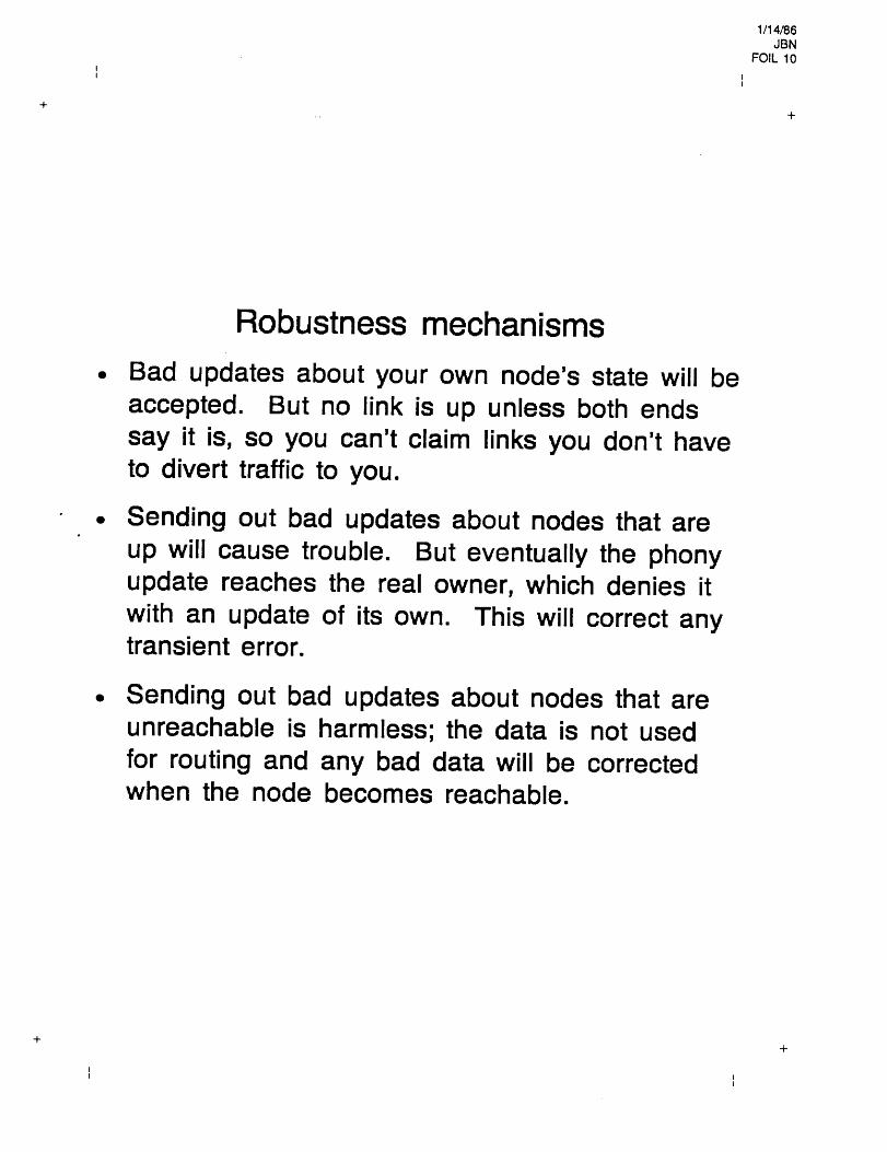
Robustness mechanisms¯ Bad updates about your own node’s state will be
accepted. But no link is up unless both endssay it is, so you can’t claim links you don’t haveto divert traffic to you.
¯ Sending out bad updates about nodes that areup will cause trouble. But eventually the phonyupdate reaches the real owner, which denies itwith an update of its own. This will correct anytransient error.
¯ Sending out bad updates about nodes that areunreachable is harmless; the data is not usedfor routing and any bad data will be correctedwhen the node becomes reachable.

1/14/86JBN
FOIL 11
Extra robustness for critical nets¯ A firewall mechanism is provided, using a
concept called "adminstrative distance", to allowsections of the network to avoid even temporarycorruption of their internal routing data. Thisreplaces the old "core network" concept with amore powerful mechanism, one which allowsproper MILNET/ARPANET isolation.
¯ Sending out bad updates repeatedly at aconsiderable rate will cause trouble only if thesource of the bad update is nearby in theadministrative distance sense. If it is nearby inthis sense, (which normally means under thesame administration), there is serious trouble.But alarms will go off; the real owner node willnotice that something very bad is happening andwill try to tell network control. Network controlcan then cut the offending node out of the net.The network will then restabilize and purge itselfof the bad routing data.

1114/86JBN
FOIL 12
Economy of routing trafficThe protocol is fully event-driven, except for akeep-alive probe. The robustness mechanismsmake this safe. (We use the keep-alive probeto validate the databases, just on generalprinciples of not trusting anything).
We don’t forget about unreachable nodes unlesswe need the table space or they areunreachable for a long time. Thus, we onlyhave to flood the net with the brief note that alink is up when a whole network becomesreachable after a short outage.
¯ This mechanism is powerful enough that wehave calculated that a 1000-node network over9600 baud lines,per five minutes,net bandwidth for
with one line outage per linkwill only use about 20% of therouting information.
1114/86JBN
FOIL 13II
Conclusion¯ We have a new approach. So far it looks good.
Please take the protocol spec home, read it, andfind its weaknesses.
¯ How about an implementation on top of 4.3BSDfor starters?

_

44444444 0oOooOoo ~oooooooOooooooo
1


t~))


i

~ ~mm m ~
~/A ~ o ~ 0k ~ir~. ~ r

--

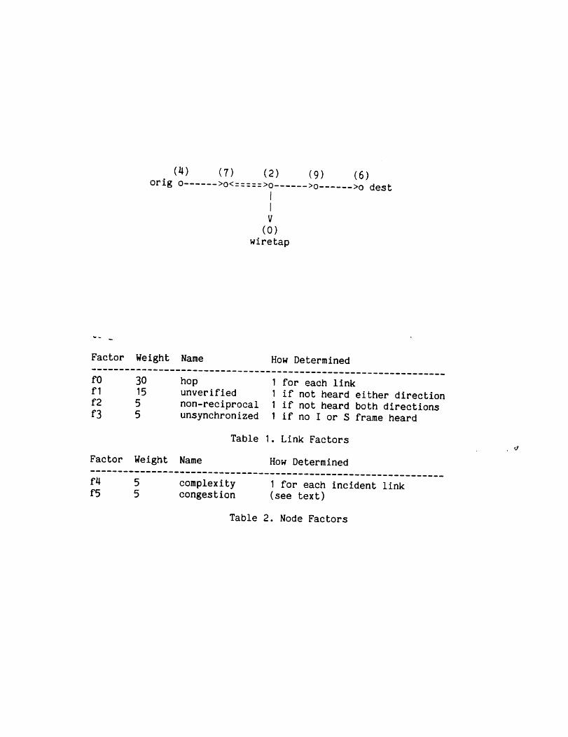
(4) (7) orig o ...... >o<:::::>o ......
V(o)
wiretap
(9) (6)>o ...... >o dest
Factor Weight Name How Determined
fo 30fl 15f2 5f3 5
hop I for each linkunverified I if not heard either directionnon-reciprocal I if not heard both directionsunsynchronized I if no I or S frame heard
Table I. Link Factors
Factor Weight Name How Determined
f4 5f5 5
complexitycongestion
I for each incident link(see text)
Table 2. Node Factors


Wiretap AlgorithmsD.L. Mills
Page
NID Callsign
0 W3HCFI WB4JFI-52 W4HCP3 WDSDBC4 DPTRID5 K4KMC6 WD4BAV7 K4ARO-I8 WB2RVX9 W3IW!10 WB4APR-611 KBSZU12 WB6RQN13 BEACON14 KA4USE-I15 MAIL16 WA4TSC17 co18 KS3Q19 WB2MNF20 KC2TN21 AK3P22 AK3P-523 KC3BN24 WA3KXG-625 KA4USE26 TEST27 K4NGC28 KA3KIW29 KA3DBK3o K3SLV31 W3HCE32 W3VH33 KE4TZ34 WA4QNO35 K4UMI-536 WB4FJI-537 WA4SZK38 K4LKQ-I39 W4ULH-I40 WB4FQR-441 N4SN42 KX3C
IP Address Flags Links Last Rec Wgt Route
[128.4.1.1] 000 14.[128.4.1.2] 006 15[128.4.1.3] 000 0[128.4.1.4] 000 0[o.o.o.o] ooo I[0.0.0.0] 007 0[o.o.o.o] ooo I[0.0.0.0] 006 I[0.0.o.o] oo7 3[O.0.o.o] 007 6[O.0.0.0] 007 9[o.o.o.o] ooo I[O.0.0.0] 003 0[o.o.o.o] ooo 3[o.o.o.o] oo7 8[o.o.o.o] ooo I[0.0.0.0] 003 0[0.0.0.0] 000 1[0.0.0.0] 007 2[0.0.0.0] 006 2[o.o.o.o] 007 3[o.o.o.o] oo7 i[0.0.0.0] 006 4[0.0.0.0] 007 2[0.0.0.0] 007 2[0.0.0.0] 003 0[0.0.0.0] 000 1[0.0.0.0] 007 0[o.o.o.o] oo7 i[0.0.0.0] 007 2[0.0.0.0] 007 I[o.o.o.o] ooo 3[o.o.o.o] oo7 o[0.0.0.0] 003 I[0.0.0.0] 000 1[0.0.0.0] 002 I[O.0.0.O] 002 I[o.o.o.o] ooo I[O.0.0.0] 002 1[0.0.0.0] 002 I[0.0.0.0] 006 ~[o.o.o.o] oo7 o[0.0.0.0] 002 2
OO:00:00 0 I16:37:56 40 -00:00:00 25500:00:00 25500:00:00 155 "~--~114:46:39 4000:00:00 115 5 714:46:39 75 516:25:42 85 1816:37:44 4016:25:45 4000:00:00 170 I16:33:17 4000:00:00 80 1615:57:59 4000:00:00 125 1015:21:45 4000:00:00 80 516:25:47 4015:05:05 120 1015:05:05 85 1814:00:07 130 24 2214:00:07 80 2405:42:41 80 2405:42:41 4015:57:57 115 1400:00:00 110 915:14:51 4011:39:26 85 2916:21:08 4013:17:19 4000:00:00 80 3012:49:21 4013:11:27 90 2900:00:00 165 5 7 3514:43:26 120 5 714:45:41 80 2700:00:00 210 5 7 38 3914:46:39 120 5 714:46:39 165 5 7 3815:05:25 75 2715:47:25 145 I16:21:08 40
Figure I. Candidate Node Table
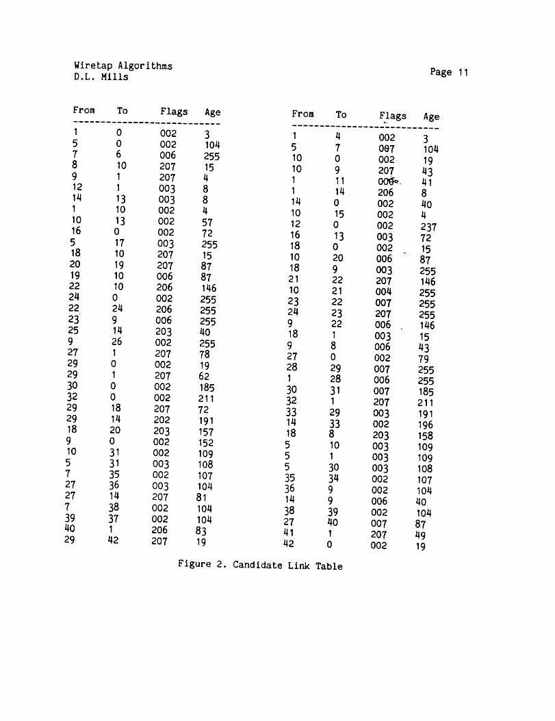
Wiretap AlgorithmsD.L. Mills Page 11
From To
1 05 0? 68 109 112 1
16 0
18 1020 1919 1022 1024 022 2423 925 149 2627 I29 029 I3O 032 029 1829 1418 209 0~o 315 317 3527 3627 147 3839 374O I29 42
Flags Age From To
002 3 I 4002 104 5 7O06 255 I0 0207 15 10 92O7 4 I 11O03 8 I 14003 8 14 0002 4 10 15002 57 12 0002 72 16 13003 255 18 0207 15 10 20207 87 18 9006 87 21 22206 146 10 21002 255 23 22206 255 24 23006 255 9 22203 40 18 IOO2 255 9 8207 78 27 0002 19 28 29207 62 1 28O02 185 30 31002 211 32 1207 72 33 29202 191 14 33203 157 18 8002 152 5 10002 109 5 1003 108 5 30o02 107 35 340o3 104 36 9207 81 14 90o2 104 38 39002 104 27 40206 83 41 1207 19 42 0
Flags..
002Oe7002-20700~.206OO2OO2OO2003O020060032070040072070050030060O20070060072070030022030030030030O20020060O2007207002
Figure 2. Candidate Link Table
Age
31041943418404237721587255146255255255146154379255255185211191196158109109108107104
40104
874919
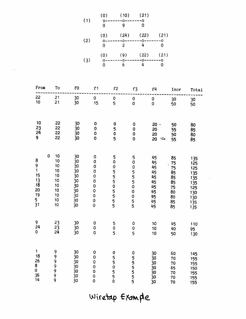
(1)
(2)
(3)
(0) (10) (21)0 0 0
0 9 0
(0) (24) (22) (21)0 0 0 00 2 4 0
(0) (9) (22) (21)0 0 0 0
0 6 4 0
From To fO f I
22 21 30 010 21 30 15
f2 f3 f4 Incr
~o50
Total
3o5o
10 22 30 0 0 0 20 -23 22 30 0 5 0 2024 22 30 0 0 0 209 22 30 0 5 0 20
50555055
80858085
0 10 30 0 5 5 45 85 1358 10 30 0 0 0 45 ~.75 1259 10 30 0 0 0 45 75 125I 10 30 0 5 5 45 85 13515 10 30 0 5 5 45 85 13513 10 30 0 5 5 45 85 13518 10 30 0 0 0 45 75 12520 10 30 0 5 0 45 80 13019 10 30 0 5 0 45 80 1305 10 30 0 5 5 45 85 13531 10 30 0 5 5 45 85 135
9 23 30 0 5 0 10 45 11024 23 30 0 0 0 10 40 950 24 30 0 5 5 10 50 130
I 9 30 0 0 0 30 60 14518 9 30 0 5 5 30 70 15526 9 30 0 5 5 30 70 1558 9 30 0 0 5 30 65 1500 9 30 0 5 5 30 70 15536 9 30 0 5 5 30 70 15514 9 30 0 0 5 30 70 155


0
0
0
0
0
0
0
r-0
I
0
0
r-
0
00
0
I
0
0 0
E.
0

E
I-- I÷
4-
o~-
! I I I+ + +i i i i
÷ + +I I i I
I I I I
I I I I
I I I
I I I
I I I
I I I
I I II) I
I I ~ I ~ I
I I t~ I .1~ I
I 0 I I (l) I
+l-. (:::) I I I ~ I
-I- + + + I~ +~ I I I I I~ I
+ + + +CO I I I I I
+ -- + + +h I I I I I
+ + + +~ ! I/~ I I I I
L/h I .1-) I I I I¯ ,i- ¢1 ÷ ÷ +...m~- I ~ I I I I
c~ I I I I I-I- + + + +
(~1 I I I I I"I--- + + + +
"" ! ! I I I-I- ~-~ + , + +
0 C) I ~-~ I I I
I I+I I
+I I
+I I
+ +I I
+I I
+ +I I
+ +I I
+I Ioi- ~ -I-I r/) I
+ .i-) +| o,-I !
+ .I:) +I I
I ~ I
I I
I I~ I
I ~ I+ I/) +I ~ I
+ I~ -I-I .r-I I
I I
I ~ I+ ~ +I I~ I
+ .~ +I ~ I"t" ,,-II &., I
+ 0 +I I
+I I
+ +I I
+ +I I
+ +I I
4- +I I
+ +I I
+ +I I
+ +I I
4-
÷
+I
+I
+I
+I
+I
+I
+I
+I
+I
+I
+I
+I
+I
+I
+I
+I
+I
-I-I
+I
+I-I-I
I+I
+I
+I
+I
+I
+I
+I
+I-I-I
+
+I
+I
+I
+I
+I
+I
+I
+I-I-I
I+I
+I
+I
+I
+I
+I
+I.
+I
+I-I-I
+I
+I
I+I
+I
+I
+I
+I
+I
+I
+I
+I
+

0
0
0
0
0
0
"{3
0
0
0 0

I ] ! I I
I I
,!

0
00
E
0
X
0e"
0
~ Xmm
0
~-- 00 0
~ X
e- (Do 3

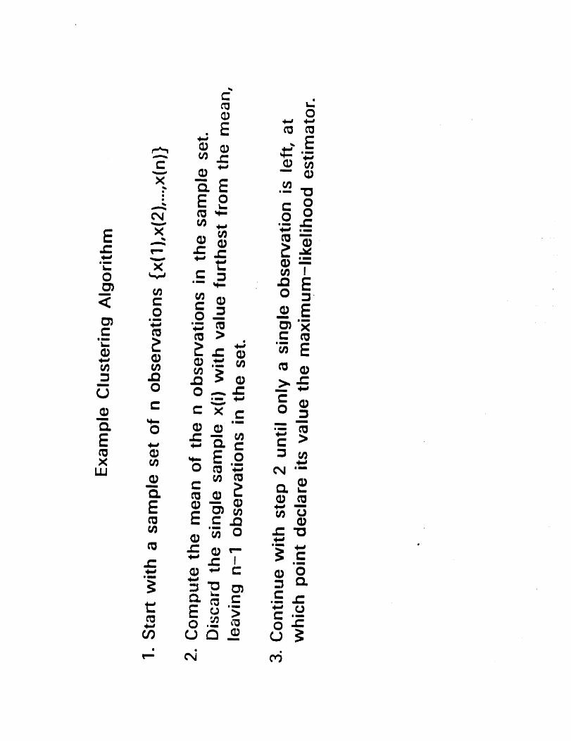
Clustering Algorithm using
Size Mean Var
ICIVIP Timestamp
Discard
Data
5O4500450400
350300250200
150100
80605040302O15108642
-3.0E+6 3.2E+14 8.6E+7-3.3E+6 2.9E+14 8.6E+7-1.6E+6 3.0E+13 -2.5E+729450 2.2E+11 3.6E+6-3291 4.1E+9 -1859343611 1.6E+9 -954452967 6.8E+8 667434047 2.3E+8 392881717 8.6E+7 21346803 1.9E+7 105181123 8.4E+6 -48631119 3.1E+6 4677502 1.5E+6 -2222432 728856 2152
84 204651 -98730 12810 33828 2446 1227 -- 454 49
-2 196 24-9 23 0-10 5 -13-8 0 -8

Comparison of .~,!go~ithms
Mean Dev Max Min
Raw data
C(5,3)
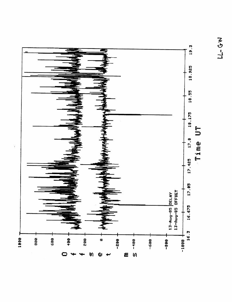
LL-GW (a)
566 1.8E+7 32750 -143
-23 81 14 -69
Majority-Subset Algorithm
Size Mean Vat Discard
1000 566 1.8E+7 32750990 242 8.5E+6 32726983 10 1.0E+6 32722982 -23 231 -143980 -23 205 -109970 -22 162 29960 -23 128 13940 -23 105 -51900 -24 89 I800 ~--25 49 -9700 -26 31 -36600 -26 21 -34500 -27 14 -20400 -29 7 -23300 -30 3 -33200 -29 I -27100 -29 0 -28I -29 0 -29
LL-GW (a) Clustering Algorithm

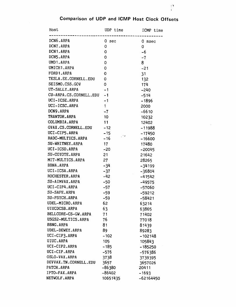
Comparison of UDP and ICMP Host Clock Offsets
Host UDP time ICMP time
DCN6.ARPA 0 secDCN7.ARPA 0DCNI.ARPA 0DCNS.ARPA 0UMDI.ARPA 0UMICHI.ARPA 0FORDI.ARPA 0TESLA.EE.CORNELL.EDU 0SEISMO.CSS.GOV 0UT-SALLY.ARPA -ICU-ARPA.CS.CORNELL.EDU-IUCI-ICSE.ARPA -IUCI-ICSC.ARPA IDCN9.ARPA -7TRANTOR.ARPA 10COLUMBIA.ARPA 11GVAX.CS.CORNELL.EDU -12UCI-CIPS.ARPA -15RADC-MULTICS.ARPA -16SU-WHITNEY.ARPA 17UCI-ICSD.ARPA -20SU-COYOTE.ARPA 21MIT-MULTICS.ARPA 27BBNA.ARPA -34UCI-ICSA.ARPA -37ROCHESTER.ARPA -42SU-AIMVAX.ARPA -50UCI-CIP4.ARPA -57SU-SAFE.ARPA -59SU-PSYCH.ARPA -59UDEL-MICRO.ARPA 62UIUCDCSB.ARPA 63BELLCORE-CS-GW.ARPA 71USGS2-MULTICS.ARPA 76BBNG.ARPA 81UDEL-DEWEY.ARPA 89UCI-CIP3.ARPA -102UIUC.ARPA 105UCI-CIP2.ARPA -185UCI-CIP.ARPA -576OSLO-VAX.ARPA 3738DEVVAX.TN.CORNELL.EDU3657PATCH.ARPA -86380IPTO-FAX.ARPA -86402NETWOLF.ARPA 10651435
0 msec0-6-78-21
31132174-240
-514-18962000-6610
1023212402
-11988-17450-1660017480-200452164228265
-34199-36804-41542
-49575-5706O-59212-58421632146386571402770188143989283-102148105843-185250
-5763863739395365702620411-1693-62164450

1114/86JBN
FOIL 1
,,
Congestion in the InternetDoing Something About It
John Nagle
Ford Aerospaceand Communications Corporation


1114/86JBN
FOIL 2
Good guys and bad guys¯ We’ve been through this before, but it’s still the
big problem.
¯ A few bad guys can ruin it for everybody.
¯ There are still a lot of bad guys.
¯ I think that proportionally the bad-guy ratio isdecreasing but but in absolute numbers thereare more bad guys than ever before.
¯ We don’t seem to be winning on this.
1/14/86JBN
FOIL 3
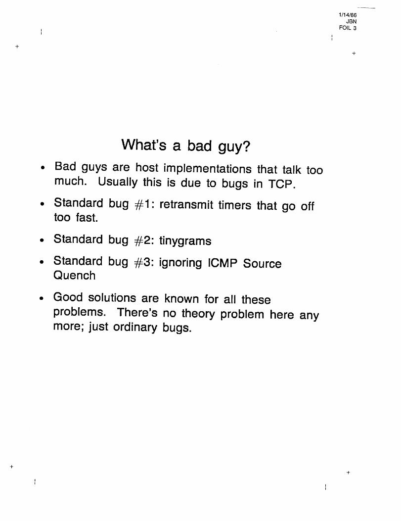
What’s a bad guy?¯ Bad guys are host
much. Usually thisimplementations that talkis due to bugs in TCP.
¯ Standard bug #1: retransmit timerstoo fast.
that go
too
off
¯ Standard bug #2: tinygrams
¯ Standard bug #3: ignoring ICMP SourceQuench
¯ Good solutions are known for all theseproblems. There’s no theory problem here anymore; just ordinary bugs.

1/14/86JBN
FOIL 4
Just how bad is it?¯ Bad implementations can easily generate an
order of magnitude more traffic than necessary.
¯ If you are out in a 9600 baud datagram net, onebad guy can kill much of the net.

1/14/86JBN
FOIL 5
Beating on the bad guys¯ Any gateway operator with good logging knows
who the troublemakers are. Today this is mostlyDave Mills and myself.
¯ There’s no effective.formal mechanism for doinganything about the bad guys.
¯ Nagging doesn’t work with the commercialvendors.
¯ Bad guys can pass DCA’s TCP "validation".
¯ The TCP spec is not tight enough to fix this."Maximum freedom for the implementor",remember? The 1984 TCP spec revision was abust; SDC ran out of money before finishing it.
¯ Fixing the bugs in other people’simplementations is the most effective approach,but expensive, and only feasible when you havesource.

1/14/86JBN
FOIL 6
Networking despite the bad guys¯ Can we make it work despite them? I think so.
¯ Look upon a bad guy as you would a programin a loop on an operating system. It’s aresource hog, but if the resource allocationalgorithms are decent, it doesn’t hurt too much.
¯ We need smarter resource allocation in ournetworks.

1114/86JBN
FOIL 7
Fair queuing¯ Basic concept: equalize resource allocation
amongst source hosts.
Individual queues for each output link for eachsource IP address. Service queues round-robinfashion. (Implementation is not too hard. SeeRFC970).
¯ Send Source Quench whenever a queue lengthexceeds 1 or 2.
¯ If you run out of buffers, take one from the endof the longest queue.
Host should thus adapt to have just the numberof packets in transit that maximizes throughputwithout building up a queue in any node.

1/14/86JBN
FOIL 8
Optional additions¯ Implement time-to-live countdown on the
Discard packets that time out.queues.
¯ Discard IP datagrams instead of sending themwhen TTL < hops remaining to destination.When this is done, the queue misses its turn inthe round-robin. This has the effect that theworst a host behaves, the less line time it gets,and the worst hosts get NO line time at allunder overload.

1/14/86JBN
FOIL 9II
Impact of fair queuing¯ Nobody has implemented it yet. But
implementation doesn’t look too hard. SeeRFC970 for a way to do the queuing efficiently.
¯ It may go intime off.
Multinet Gateway,but that is some
¯ We need to try it and see what happens,preferably in a gateway with substantial memoryresources.
¯ Incidentally, more memory in the gateways willnot by itself control congestion, and may make itworse, although it provides some relief fromshock loads. We have some amusingexperimental data obtained with a 10,000 buffergateway.
1/14/86JBN
FOIL 10
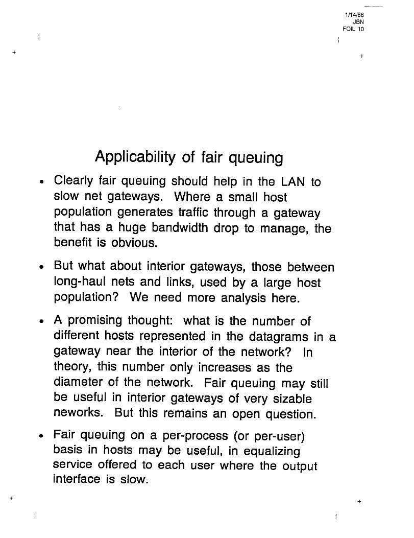
Applicability of fair queuingClearly fair queuing should help in the LAN toslow net gateways. Where a small hostpopulation generates traffic through a gatewaythat has a huge bandwidth drop to manage, thebenefit is obvious.
But what about interior gateways, those betweenlong-haul nets and links, used by a large hostpopulation? We need more analysis here.
A promising thought: what is the number ofdifferent hosts represented in the datagrams in agateway near the interior of the network? Intheory, this number only increases as thediameter of the network. Fair queuing may stillbe useful in interior gateways of very sizableneworks. But this remains an open question.
Fair queuing on a per-process (or per-user)basis in hosts may be useful, in equalizingservice offered to each user where the outputinterface is slow.
1/14/86JBN
FOIL 11
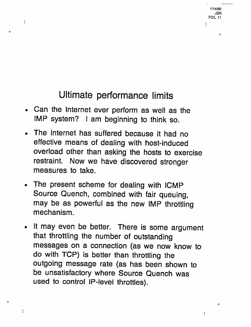
Ultimate performance limits¯ Can the Internet ever perform as well as the
IMP system? l am beginning to think so.
The Internet has suffered because it had noeffective means of dealing with host-inducedoverload other than asking the hosts to exerciserestraint. Now we have discovered strongermeasures to take.
¯ The present scheme for dealing with ICMPSource Quench, combined with fair queuing,may be as powerful as the new IMP throttlingmechanism.
It may even be better. There is some argumentthat throttling the number of outstandingmessages on a connection (as we now know todo with TCP) is better than throttling theoutgoing message rate (as has been shown tobe unsatisfactory where Source Quench wasused to control IP-level throttles).
1/14/86JBN
FOIL 12II
What about non-TCP data?¯ Most UDP-based protocols are inquiry-response.
Only ones with very short retransmit timersshould cause real trouble.
¯ Fair queuing will keep them under control. Butbad guys may lose.
¯ Someday someone will do a Sun NFS remotefile system mount across the lnternet. This willbe interesting.

1/14/86JBN
FOIL 13II
What about the ISO protocols¯ In TP4, the rules require long retransmission
timers; RTT > TTL. Good for congestion, badfor noisy nets. But CCITT’s priority is to protectthe network.
¯ In general, TP4 seems to have constantsspecified where TCP is adaptive.
¯ The tinygram fix won’t work in TP4, because itis a block protocol. We will have to fall back toPAD timers in whatever replaces TELNET.
¯ Is there a Source Quench for ISO NP/TP4?
¯ It may be necessary to go with an NP-levelthrottle; with the long retransmission timers, thiswon’t usually cause retransmits.
¯ Virtual terminal operations may beunder TP4 than under TCP.
more sluggish
1/14/86JBN
FOIL 14
,,
Why not just use virtual circuits?¯ It may come to that.
now offering a virtualEven the IMP system iscircuit interface.
¯ We may want to use the techniques here ingateways that connect LANs to virtual circuitnets. We thenvirtual circuits,process.
need only gateway to gatewaynot host to host or process to
¯ The commercial packet nets have very restrictedideas about per-circuit bandwidth and packetsize; they’re still thinking terminal-to-host.

1114/80JBN
FOIL 15II
Conclusions¯ We know enough to attack Internet congestion.
¯ It can be fixed piecemeal, gateway by gatewayand host by host.
¯ The implementation isn’t that tough.
¯ We don’t have to go to virtual circuits, althoughwe may want to.
¯ Let’s get a test going.

Host Groups:A Multicast Extension forDatagram lnternetworks
David CheritonSteve Deering
Stanfo rd U nive rs ity


Why multicast?
¯ efficient multi-destination delivery
¯ updating a replicated database
¯ conferencing
¯ parallel computing
¯ unknown-destination delivery
¯ querying a distributed database
¯ finding a network boot server
¯ disseminating routing tables

Why not broadcast?
¯ incurs overhead on uninterested hosts
¯ more overhead with each new application
¯ unwanted listeners
¯ too expensive for large internetworks
¯ directed broadcast constrained by topology

The Host Group Model
A host group is a set of zero or more hosts.
¯ an address identifies a group, not a host
¯ ,static or dynamic membership
¯ permanent or transient groups
¯ special case: permanent, static group of 1
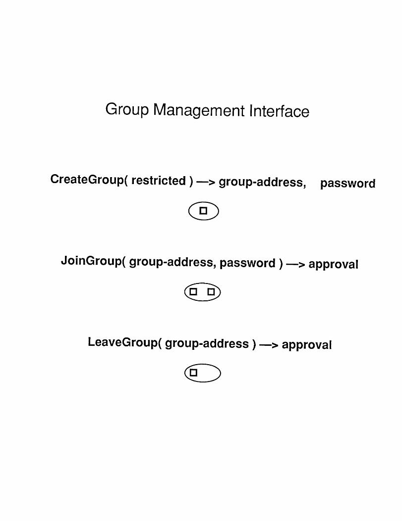
Group Management Interface
CreateGroup( restricted )--> group-address, password
JoinGroup( group-address, password )--> approval
LeaveGroup( group-address )---> approval
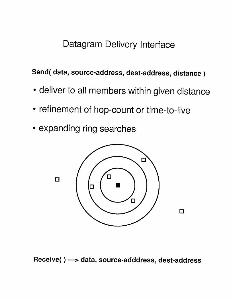
Datagram Delivery Interface
Send( data, source-address, dest-address, distance
¯ deliver to all members within given distance
¯ refinement of hop-count or time-to-live
¯ expanding ring searches
E!
Receive( )~> data, source-adddress, dest-address
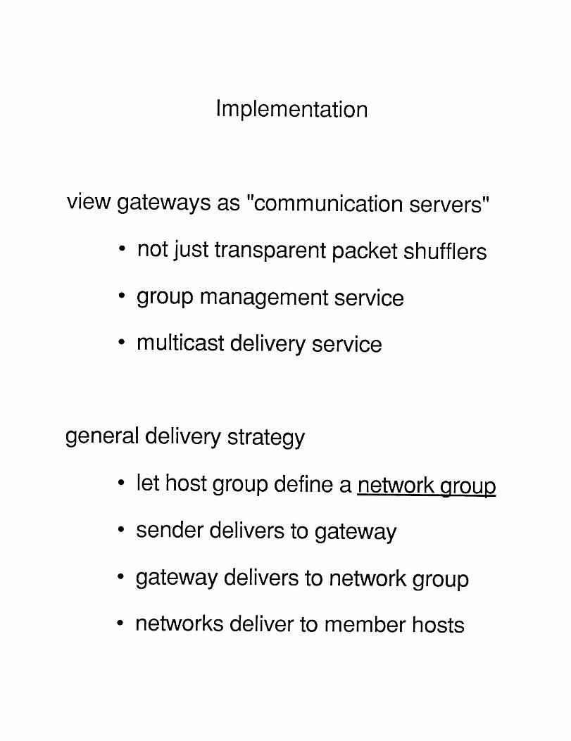
Implementation
view gateways as "communication servers"
¯ not just transparent packet shufflers
¯ group management service
¯ multicast delivery service
general delivery strategy
¯ let host group define a ,,network group
¯ sender delivers to gateway
¯ gateway delivers to network group
¯ networks deliver to member hosts

gateway data structures
¯ routing table
¯ network membership table
¯ local host membership table
A , ~lal
Igrp 1: A
grp 1: a1
C
B I
Igrp2: C,D
grp 2" C1,c2
C1 C2
D I
grp 2: C,D
grp 2: d1
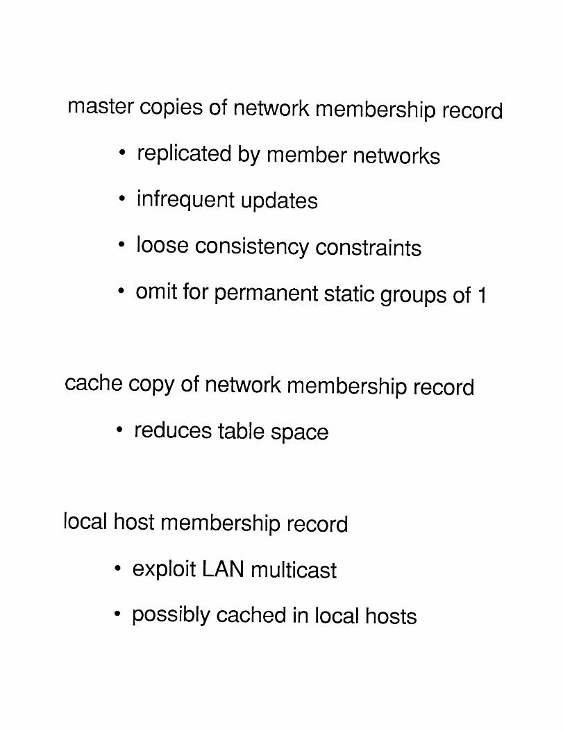
master copies of network membership record
¯ replicated by member networks
¯ infrequent updates
¯ loose consistency constraints
¯ omit for permanent static groups of 1
cache copy of network membership record
¯ reduces table space
local host membership record
¯ exploit LAN multicast
¯ possibly cached in local hosts

handling a cache miss
¯ separate or piggybacked query
¯ muiticast to gateway group
¯ expanding ring search
¯ "pruned multicast"
handling stale cache data
¯ detect on use
¯ checksum network membership record
¯ time out unused records
intergateway routing
¯ shortest-distance spanning tree
¯ extended reverse path forwarding(Dalai and Metcaife)

Extensions / Refinements of I P
¯ host group addresses
-"class D" addresses used for groups
- some reserved for permanent groups
- mapped to local multicast addresses
- restricted to destination field?
¯ IGMP for creating/joining/leaving groups
¯ distance control refinement of time-to-live
¯ minor change to ICMP Echo specification

Experiment Multicast Agents
¯ "black boxes", outside of gateways for now
- add extra hops to delivery path
no access to routing informationmust use wired-in knowledge
¯ useful for investigating:
-internetwork multicast routing
-internetwork group management
- applications of internet multicasting

Some gritty details
¯ source route insertion/deletion for relaying
¯ extended ARP for Ethernet mapping
¯ different Ethernet packet type to avoid"destination unreachable" advisories
¯ delayed replies to ICMP Echo requests

What do we seek from this task force?
critical comment on our multicast pand plans for experimentation
roposal
¯ consideration of multicast requirements indesign of next-generation routing protocols
¯ consideration of multicast as a solution tosome internet problems, e.g...
locating gatewayslocating name serversexchanging routing info rmation
¯ discourage proliferation of broadcast-basedprotocols, such as ARP or. BOOTP

C. (X ~< R E t~
5 //W’PC tF y"

G


I,C "O0oo ~h’ ’

rE]"
,Y
/VET E/VT(Tt~ TI T/_.E.f~

Y
N
1’4
Y
YN
Y


APPENDIX B
Papers Distributed at GADS Meeting
Distributed By: Paper
J. Nagle Gateway Database Protocol
Mathis Automated Reconstitution Using Airborne Packet Radios
A. W. Brown Merit: Michigan’s Universities’ Computer Network
Misc. - Milnet Name Domain Transition Plan
- Proposed DDN Bulletin Regarding EGP Table Space
- Internet MAP
*Note: See Reading List In Minutes For Other Papers Important To This Meeting
126


0
D
U.I
LU0

66
Z
Z
I
Z

0 Z
Z
I.kl

II
Z
Z
0
I.U
U.,I
I.UZ
0
Z
0I-0
71

0
0
I,.U
O
Z
Z0
Z>-
>-~D0
0
o’P,
Zn,"n*"
o
~.~ .;- .:oOoO
73

__.0
I I
75

I
Z0
Z>-
LU
>0
Z
0
I-.-
0
ZI
Z
ZI
0
0
Z
76
II
78
Z
~’~ZI- z
Z
0 I-
0I-- z
Z I--
~ 00 r~u_ 0
~: z
0 I -." I


82
Z
U.,II--:D0

Z
z
,~o
83
Merit:
Michigan’s
Universities’
Computer
Network
by
Eric M. Aupperle
January 1986


Preface
The Merit Computer Network Project began late in 1969 with
the objective of linking several of Michigan’s public university
computing centers together in a resource sharing data communi-
cations network. Merit first provided operational service in 1972
and continued development of new services and capabilities over the
ensuing years. Merit operated exclusively as an interuniversity
network throughout the 1970’s. In the 1980’s Merit’s networking
technology was selected first by The University of Michigan and
subsequently by Wayne State and Western Michigan Universities to
serve as elements of these universities’s internal data networks.
Within the University of Michigan this network is known as
UMnet. UMnet serves all three of Michigan’s campuses, Ann Arbor,
Dearborn and Flint. Much of Merit’s recent expansion results from
the UMnet component. This was made possible by merging the U-M’s
Computing Center Data Communications staff with Merit’s staff. This
marriage produced the rapid developments in both network related
hardware and software during the last four year period.
Wayne State and Western Michigan Universities respectively
adopted the names WSUnet and WMUnet for intrauniversity implement-
ations which include Merit’s technology. Both buy their Merit
network hardware from the University of Michigan’s Computing Center
where the resources exist to fabricate and assemble this equipment.
WSU is implementing a WSUnet access ring around the city of Detroit
to serve its suburban students and faculty. WMU provides service to
its extension students with its Grand Rapids node.
Within this report the name Merit is commonly used to
reference network components even though sometimes UMnet, WMUnet or
WSUnet could alternatively be mentioned. This is done to simplify
the narrative. It is important to recognize that while Merit/
UMnet/WMUnet/WSUnet is an integated network; its inter and intra
university manifestations are separately funded and administered.
The following pages show an outline map of Michigan detailing
the intercity network links connecting Merit’s major switching
nodes, links to other networks and remote to Michigan sites, and
Michigan access sites. Merit’s member universities are:
Michigan State University Oakland UniversityUniversity of Michigan Western Michigan University
Wayne State University
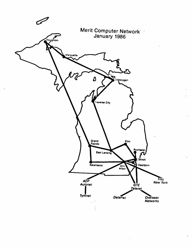
ghton
Merit Computer NetworkJanuary 1986
Marquette
boygin
City
Flint
Arbor
ADPAutonet
ITymnet
,yNew York
GTETelenet
DataPacNetworks

CitiesMerit
with Access Numbers toand Affiliated Networks
~ghton
Marquette
Network Access
Autone, ~ [~ Merit
Tymne, ~] E~’re,enet
Peto~key
Manistee
City

Table of Contents
Introduction ............................... 1
Merit’s Hardware ......................... ii
PCP System Description .................. II
SCP System Description .................. 15
Internodal Communication Lines .......... 16
Merit’ s Software .......................... 18
Virtual Connections .................... 18
User Hosts ............................. 19
Server Hosts ............. - .............. 21
Other Hosts ............................ 22
System Software ........................ 23
Appendix .................................. 26
Host Tables ............................ 26
PCP/SCP Connection Diagrams ............ 30
List of Figures
Fig. 1 Simplified Merit Configuration Diagram ......... 3
Fig. 2 PCP/SCP Hierarchchy ............................ 5
Fig. 3 SCP Interconnection Services ................... 7
Fig. 4 The ARPAnet Gateway’s Interconnection .......... 8
Fig. 5 The Planned USAN Network ........................ 9
Fig. 6 The SDSC Consortium ............................ I0
Fig. 7 PCP Block Diagram .............................. Ii
Fig. 8 MMI6 Block Diagram ............................. 13
Fig. 9 SCP Block Diagram .............................. 15
Fig. I0 Virtual Connection Illustration ............... 18
Fig. II MCP and Related Support ....................... 20
Fig. 12 Some Host/Node System Software Components ..... 23
Fig. 13 CCOS Software Block Diagram ................... 25

Introduction
This report describes Merit’s implementation and the current
configuration of the network. Hopefully the reader will have a
better understanding of such things as PCPs, SCPs, hosts, Hermes,
X.25 and many other network related terms and concepts after
reading this tutorial. It begins with an overview of the current
system diagram and uses this to introduce several concepts. From
these beginnings, various details and other topics emerge.
In part, the network exists to interconnect terminals or
workstations to hosts and to interconnect hosts and workstations
with each other. Hosts are computing systems which provide such
services as alternative programming languages, text processors,
various editors, a file system and data base systems. Usually a
host is specified by its hardware and operating system; for
example, a DEC VAX 780 running UNIX or an Amdahl 5860 running MTS.
In the configuration diagram, hosts appear as boxes. The first
line of each box identifies a host’s general location, the second
its hardware and the third its operating system as shown in the
following example.
DEC: UI%X 780U~IIX
Many of the hosts attach to the network’s Primary
Communication Processors, commonly identified as PCPs. PCPs are
Merit:s switching nodes and are described in greater detail in the
next section. The configuration diagram identifies them with the
following symbol. The two letters in the second line represent
the PCP’s network name, e.g., EL is the PCP at Michigan State
University located in East Lansing.
Hosts are attached to network nodes in four ways. Two of
these are by a high speed, parallel channel interface, i.e.,
similar to the way disks or magnetic tape drives connect to
computers or by a serial X.25 communications link, e.g., over a
Xntroduct£on 1 ~anuary 7, 1986

dedicated telephone line. The former requires a PCP to be located
near its host, usually within a few meters. The latter has no
distance limits, is less costly but slower. All of the large hosts
operated by the Merit university computing centers use a channel
interface. Most minicomputer hosts use an X.25 link. The other
two ways to attach hosts will be explained soon.
Since the network exists to interconnect workstations and
hosts, the PCPs must be interconnected. Telephone circuits rented
from AT&T, Michigan Bell or our own twisted pair wires provide this
service. Within the U-M’s Ann Arbor campus some of the links
operate on coaxial cables to transmit the network’s data more
rapidly. Later fiber optic tubes and microwave links between Ann
Arbor, Flint and Dearborn may be used for the same purpose too.
Figure I is a simplified diagram of the current Merit config-
uration. It’s simplified in the sense that it omits showing how
most terminals and workstations are connected and in some other
details too. Even so, this figure reveals a great deal about the
network’s backbone and some of its hosts. It shows the network
linking sixteen hosts through eighteen PCPs and serving Ann Arbor,
Cheboygan, Dearborn, Detroit, East Lansing, Flint, Grand Rapids,
Houghton, Kalamazoo, Marquette, and Traverse City. Later we will
learn other cities and hosts also are served by the network. All
the identified hosts may be accessed from these Michigan cities
directly through Merit.
Observe that this configuration diagram uses line widths and
shadings to show the connection between a host and its associated
PCP, and for the inter-PCP links. The wide solid lines signify
channel-attached hosts. The X.25 attached hosts use wide patterned
lines while the inter-PCP links appear as narrow solid lines.
Another feature of this diagram is the presence of the GTE
Telenet and ADP Autonet networks. Our network interconnects with
both these nationwide commercial systems. Merit dually links with
GTE Telenet through Ann Arbor and Detroit based PCPs and connects
with ADP’s Autonet on a different Ann Arbor PCP. These commerical
networks afford access to Merit and its hosts from all around ourcountry or beyond, and workstations on Merit may access hosts on
either of these systems or yet other hosts on networks linked with
them in an expanding worldwide computer communications system.
Introduction 2 January 7, 1986

Fig. I Merit’s PCP Backbone Configuration
Introduction 3 Janua~ 7, 1986

In addition to hosts, other networks and Merit’s own PCPs,
Figure 1 shows two Apollo rings. Apollos are powerful workstations
with excellent graphics facilities. These workstations function
most effectivel~ when several are interconnected in a ring, in a
baseband local area network. The U-M’s College of Engineering
provides its students and faculty with two such rings, one on the
North Campus and the other on the Central Campus. Each of these
rings uses an X.25 connection to link with Merit. MSU’s Computer
Laboratory installed a Contel coaxial cable network to serve its
users; this also connects to Merit with an X.25 link. Soon other
local area networks, LANs, will interconnect with Merit too.
One final point to make about this diagram is the PCP naming
convention. Names like FL for Flint, KZ for Kalamazoo; and MQ for
Marquette seem obvious. So is AN for Ann Arbor. They are either
the first or only PCPs in these cities. Ann Arbor has several
newer ones; they require names too for the network’s data routing
to work properly. The AB, AD and AE names stem from the U-M’s Data
Concentrators which these PCPs.replaced. An AA PCP exists too; it
currently acts as a network software testing system. The one
remaining Data Concentrator will become AC after its conversion to
a PCP. It follows that Wayne State University’s newer PCP’s be
named DA and DB. CN’s name derives from the CIPRNET DEC VAX cluster
it serves. This leaves only U-M Dearborn’s OH PCP name for the
reader to speculate about.
Now that hosts, PCPs and other networks are clearly in mind
what about the terminals and workstations? Some connect to PCPs
but most attach to Secondary Communication Processors, the SCPs.
SCPs are smaller versions of PCPs and are primarily used to connect
clusters of terminals or workstations, e.g., personal computers, to
Merit. SCPs may also be used to support serial printers, provide
local X.25 ports, attach hosts through asynchronous ports, and link
LANs. These concepts will be clearer after Figure 2 is explained.
Figure 2 complements Figure I by showing the hierarchical
relationship of the network’s one hundred plus SCPs with the PCP
backbone. Actually each SCP has an individual link to its PCP but
liberties were taken here to minimize these details. Figure 2
shows the network’s other hosts ~nd equipment, e.g., printers,
serviced by the SCPs too. Note some hosts and the Apollo rings are
connected both to PCPs and SCPs. By mentallysuperimposing
Xntroduct£on 4 January 7, 1986

181-H~
Fig. 2 The PCP/SCP Hierarchy
Introduction 5 Janua~ 7, 1986

Figures 1 and 2 one may form a picture of the entire network.
Secondary Communication Processors are physically smaller thanPCPs, use less powerful computers and cost less. Each SCP connects
to a PCP through a Serial communication link of the same type used
between PCPs. As the PCPs, the SCPs need names in order for the
network to correctly route data traffic. SCPs are given four
character names like UNYI and ENG4. Usually these names reflect
either the SCP’s location or its owner.
Each SCP may support up to eighty-eight terminals or work-
stations at data rates as high as 19.2 kbps. Few SCPs are fully
configured; more typically each has between twenty and thirty
terminals attached. Today the network has over 120 operational
SCPs. The majority of the SCPs reside in Ann Arbor and form the
dominant part of UMnet as do the SCPs in Flint and Dearborn. The
other concentration of SCPs occurs in Detroit. Wayne State
University owns most of these units as part of its emerging WSUnet.
Recently units of the State’s government have purchased SCPs too.
While SCPs primarily support directly attached terminals or
workstations, an SCP port can also attach to a serial printer and
have output routed to it from elsewhere in the network. Several
printers already are attached to SCPs as indicated in Figure 2.
Figure 2 also shows many hosts attached to various SCPs. This
represents the third way of connecting a host with the network; a
method known as asynchronous host support. This method connects
several of an SCP’s terminal ports to the similar input ports of a
host. The several SCP ports assigned to an asynchronously attached
host are treated as a group by the network and appear as one host
name, e.g., DSC or UMLIB. Whenever a user tries to open a
connection to such a host, the local SCP selects any free port in
this group for it. This method of host attachment is very easy for
hosts and hence is quite popular even though it is inefficient and
slow relative to the other two methods. The network already
supports 38 hosts through such interfaces as detailed in Figure 2.
Figure 3 illustrates the full range of SCP services, including the
fourth way to attach hosts by an Ethernet LAN.
Some of Merit’s external network connections were describedearlier but there are others of growing importance. WSU’s Computer
Services Center provides access to BITNET thrbugh its IBM 3081
Introduction 6 J’anuary 7, 1986

Link to8CP
-- Terminal or~
-- Workstation
ii
Fig. 3 SCP Intercon~ection Service
host, see Figure I. The U-M’s Electrical Engineering and Computer
Science department operates a CSNET link from their DEC VAX cluster
as Figure 2 indicates. Both these networks are of national import-
ance within the university community.
A venerable, important, and famous network is the ARPAnet
operated by .the U.S. government. Merit links with it through a
gateway processor jointly finance~ by the U-M’s College ofEngineering and the U-M Computing Center. The gateway consists of
a DEC PDP 11/73 system running DCnet software:from Linkabit. This
gateway is accessible both as an asynchronous host on Merit and
Introduction 7 January 7, 1986

through its Ethernet interface as shown in Figure 4. Currently a
9.6 kbps link connects the gateway to a similar system at
Linkabit’s office in Vienna, Virginia and from there a direct ARPA
IMP (an IMP is like a Merit PCP) connection over a 56 kbps circuit
completes this path.
The further significance of the Ethernet shown in Figure 4 is
that it will soon serve as an important element in Merit’s NSFnet
connections. Satellite links to the USAN experiment and San Diego
Supercomputer Center are expected early in 1986. Figures 5 and 6
give additional details.
n
Fig. 4 The ARPAnet Gateway’s Interconnection
This concludes the overview. The next section discusses the
network’s hardware in more detail and following that is a
description of the network’s soft’ware from both a user’s and a
system’s viewpoint. This report ends with an Appendix diagramming
each PCP’s links and contains a listing of all the network’s hosts.
Introduction 8 January 7, 1986

NCAR, Boulder, ColoradoOregon State University, Corvallis, Oregon
University of Illinois, Urbana, IllinoisUniversity of Maryland, College Park, Ma~land
University of Miami, Miami, FloridaUniversit~ of Michigan, Ann Arbor, MichiganUniversity of Wisconsin, Madison, Wisconsin
Fig. 5 The Planned USANNetwork
Introduction 9 Janua~ 7, 1986

Agouron Institute, La Jolla, CaliforniaCalifornia Institute of Technology, Pasadena, California
National Optical Astronomy Observatories, Tucson, ArizonaResearch Institute of Scripps Clinic, La Jolla, California
Salk Institute for Biological Studies, San Diego, CaliforniaSan Diego State University, San Diego, California
Scripps Institute of Oceanography, La Jolla, CaliforniaSouthwest Fisheries Center, La Jolla, California
Stanford University, Stanford, CaliforniaUniversity of California-- Berkeley, Berkeley, California
University of California -- Los Angeles, Los Angeles, CaliforniaUniversity of California -- San Diego, La Jolla, California
University of California -- San Francisco, San Francisco, CaliforniaUniversity of Hawaii, Honolulu, Hawaii
University of Maryland, College Park, MarylandUniversity of Michigan, Ann Arbor, Michigan
University of Utah, Salt Lake City, UtahUniversity of Washington, Seattle, WashingtonUniversity of Wisconsin, Madison, Wisconsin
Fig. 6 The SDSC Consortium
Introduction 10 January 7, 1986
Merit’s Hardware
The network’s hardware primarily consists of PCPs, SCPs and
the communication channels which interlink these nodes. This
section describes the PCP and SCP architecture and identifies the
names of their key components. An overview of the interconnecting
communication channels in current use appears too.
Both PCPs and SCPs incorporate Digital Equipment Corporation,
DEC for short, central processing units. The PCPs use DEC
minicomputers, i.e., the PDP 11/34 or PDP 11/60 processors. The
SCPs are based on DEC microcomputers, now usually PDP II/23s and
PDP ii/73s. Most PCPs and SCPs contain 128k 16-bit words of memory.
Both PCPs and SCPs make use of DEC’s memory management hardware.
Neither PCPs nor SCPs rely on disks or any other form of local
permanent memory except for a small ROM used for loading, dumping
and diagnostic analysis.
PCP System Description
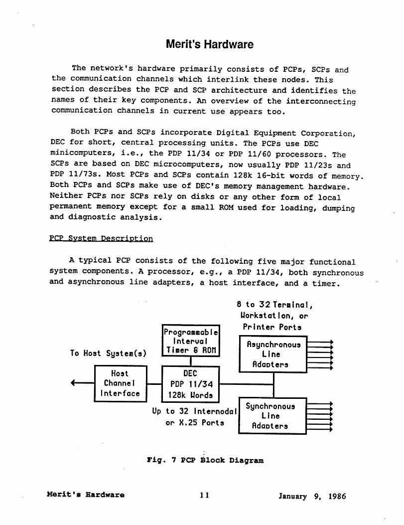
A typical PCP consists of the following five major functional
system components. A processor, e.g., a PDP 11/34, both synchronous
and asynchronous line adapters, a host interface, and a timer.
To Host System(s)
Host
ChannelInterface
ProgrammableIInterval ~ Asynchronous
Timer ~ ROM~ LineRdaoters
PDP II/34
I 128k Words
ISynchronou,Up to 32 Internodal Line
or X.25 Ports Rda~ters
8 to 32 Terminal,Workst at I on, orPrinter Ports
Fig. 7 PCP Block Diagram
Merit ’ s Hardware 1 1 January 9, 1986
The four devices interfaced with the processor each have
special functions. The Asynchronous Line Adapters provide the
communication ports to serve individual terminals or workstations.
Typically these ports may operate at several different data rates
to accommodate the needs of the terminal equipment. The maximum
rate is either 9.6 kbps or 19.2 kbps depending on the specific
hardware used, i.e., commercial DZ or DL equipment, or our own LA32
hardware. These latter 32 port asynchronous Line Adapters are
considered obsolete and are being phased out of operation. The long
term plan is to have most, if not all, of the asynchronous support
provided by the SCPs.
Most of the PCPs’ asynchronous line adapter ports are
connected to modems for dial-up access to the network so most of
these ports actually operate at either 300, 1200, or 2400 bps. The
300 bps ports also support 110 and 150 bps rates using an automatic
baud rate selection mechanism. The Asynchronous Line Adapter
equipment is.the hardware used to provide Merit’s Hermes terminal
support. Most of Hermes’s functionality is derived from software;
this is explained in the next section.
The timer unit is really three independent devices, a
Programmable Interval Timer, a Diagnostic Control Panel and a ROM
unit. This combination device, designed and built by the network’s
staff, serves the following functions. As a timer it provides
crystal controlled time intervals for the PCPs software needs.
These needs include time-of-day calculations and the many timer
functions needed to support the network’s various communication
protocols. The control panel allows the network’s engineers and
programmers to examine or alter memory and input/output interface
register locations, to monitor the processor’s system bus and to
initiate processor interrupts for test purposes. The ROM unit
stores several short programs for loading or dumping the PCP from
either its host or over the network, and for diagnostic work when
the PCP has crashed or is otherwise being tested.
The host channel interface allows communication of commands,status information and data between a host, e.g.i an Amdahl 5860,
and a PCP. The data exchange at very high rates through parallel,
direct memory access transfers. E@ch type of host requires its ownspecial channel interface. The interfaces used on IBM or Amdahl
hosts were designed and are built by the network’s staff. MSU’s
Merit’s Hardware 12 January 9, 1986
channel interface to its CDC 750 is a remnant of Merit’s original
network hardware contract let in 1970. The WMU DEC 1099 interface
and the CIPRNET VAX interfaces are commercial units, a DTE-20 and
DA-IIBJ respectively. Each of these devices requires its own
special support software in the PCP. This software is known as the
Rare code because it is not common to all PCPs.
While most PCPs feature one host interface, more than one may
be supported by both the network’s hardware and software. WSU’s DT
PCP demonstrates this case; it has two, one to the WU host and the
second to the WS host. Alternatively, a PCP may not have a host
interface, e.g., the FL PCP at UM-Flint. The presence of host
channel interfaces exemplifies one of Merit’s unique features
relative to other packet-switched networks.
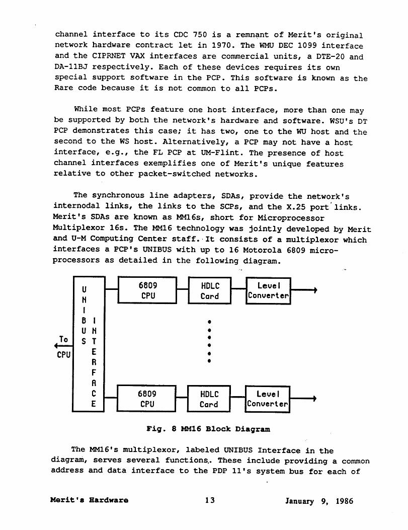
The synchronous line adapters, SDAs, provide the network’s
internodal links, the links to the SCPs, and the X.25 port’links.
Merit’s SDAs are known as MMI6s, short for Microprocessor
Multiplexor 16s. The MMI6 technology was jointly developed by Merit
and U-M Computing Center staff.. It consists of a multiplexor which
interfaces a PCP’s UNIBUS with up to 16 Motorola 6809 micro-
processors as detailed in the following diagram.
UHIB IU HS T
ERFRCE
To
CPU
6809
H HDLCCPU Card
LevelConverter
CPU Card erIConvert
Fig. 8 MMI6 Block Diagram
The MMI6’s multiplexor, labeled UNIBUS Interface in the
diagram, serves several functions.. These include providing a common
address and data interface to the PDP ll’s system bus for each of
Merlt’s Hardware ]. 3 Janua~ 9, 1986

the up to sixteen microprocessors, prioritizing both interrupt and"
direct memory access requests from the micros, and permitting the
PDP ll’s software to collectively or individually enable them.
Each microprocessor system, labeled as a 6809 CPU, is
fabricated on its own printed circuit card. This card contains a
Motorola 6809 microprocessor, a Motorola DMA controller, both RAM
and ROM memory, and essential interfacing circuitry. Three of the
DMA’s four channels are used. One each to transfer data to and from
the HDLC card and the third to transfer data and commands to and
from the PDP ll’s memory. The 6809’s main functions are to support
the HDLC chip, manage data transfers between it and the PDP II, and
provide receive data buffers in its local memory. While these may
not seem very important, they relieve the PDP Ii from the drudgery
of individual synchronous line control. This, in turn, allows the
PDP ll’s software to concentrate on higher level activities.
The acronym HDLC stands for High-level Data Link Control. This
international standard link level communication protocol replaces
the older Binary Synchronous protocol made famous by IBM in many
newer data communication systems. In Merit elements of HDLC provide
the basis for reliable communication between two node pairs. In
Figure 8 the block named the HDLC card contains an integrated
circuit chip which provides the primary functions required to
support the HDLCprotocol. This chip has independent transmitter
and receiver functions and routinely operates in full-duplex mode.
The last component of the MMI6 is a Level Converter card. This
card converts the standard TTL integrated circuit level digital
signals into those voltages or currents required bY various
external equipments. There are two versions of this card. The most
commonly used one is an RS-232 converter which permits
interconnections with the typical modems used in the network. An
RS-449 converter also was developed and used in selected cases.
The MMI6’s modular system design allows for various
applications. Its interchangeable level converter serves only as a
simple example of-this concept. Since providing synchronous ports
for the network represents the sole operational use of the MMI6s,
this section omits further comments about its modularity. Lastly,the MMI6 system design permits i~dividual port data rates in excess
of one megabit per second with appropriate level converters.
Merit ’ s Hardware 1 4 January 9, 1986
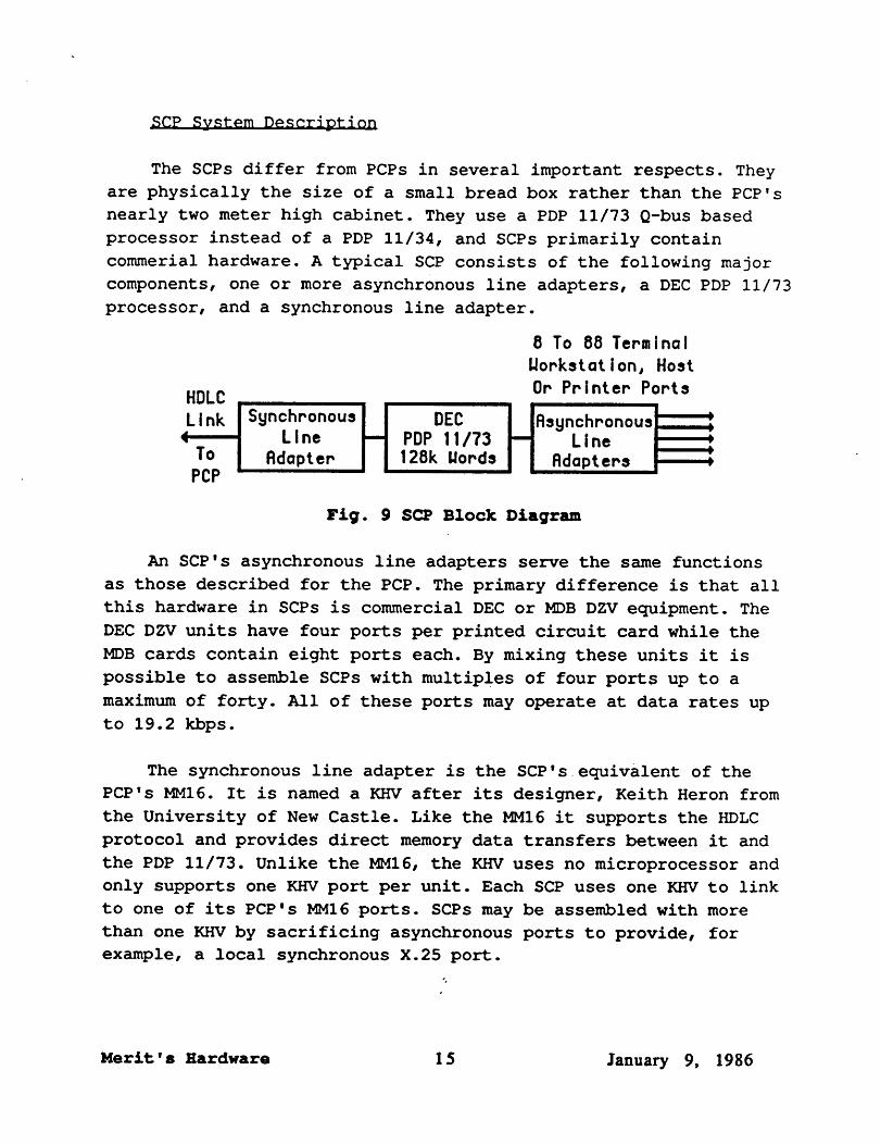
SCP System Description-- --
The SCPs differ from PCPs in several important respects. They
are physically the size of a small bread box rather than the PCP’s
nearly two meter high cabinet. They use a PDP 11/73 Q-bus based
processor instead of a PDP 11/34, and SCPs primarily contain
commerial hardware. A typical SCP consists of the following major
components, one or more asynchronous line adapters, a DEC PDP 11/73
processor, and a synchronous line adapter.
HDLCLink
ToPCP
SynchronousLlne
Adapter
8 To 88 TermlnalWorkstatlon, HostOr Prlnter Ports
H DEC HAsynchronousPDP 11/73 Line128k Mords Rdapters
An SCP’s asynchronous line adapters serve the same functions
as those described for the PCP. The primary difference is that all
this hardware in SCPs is commercial DEC or MDB DZV equipment. The
DEC DZVunits have four ports per printed circuit card while the
MDB cards contain eight ports each. By mixing these units it is
possible to assemble SCPs with multiples of four ports up to a
maximum of forty. All of these ports may operate at data rates up
to 19.2 kbps.
The synchronous line adapter is the SCP’s~equivalent of the
PCP’s MMI6. It is named a KHV after its designer, Keith Heron from
the University of New Castle. Like the MMI6 it supports the HDLC
protocol and provides direct memory data transfers between it and
the PDP 11/73. Unlike the MMI6, the KHV uses no microprocessor and
only supports one KHV port per unit. Each SCP uses one KHV to link
to one of its PCP’s MMI6 .ports. SCPs may be assembled with more
than one KHVby sacrificing asynchronous ports to provide, for
example, a local synchronous X.25 port.
Merit’s Hardware 15 Januaw 9, 1986

The only non-commercial hardware in SCPs is the KHV card and asecond one which supports the status lights on the SCP’s front ¯
panel, a ROM for loading, and an operator’s console. These cards,
the PDP 11/73, its memory, and the DZV cards are mounted in a small
cabinet which contains the necessary power supplies and a line
clock. This cabinet constrains the number of asynchronous ports
available in an SCP. Its line clock serves the SCP as the
Programmable Interval Timer does the PCP.
Internodal Communication Lines
The final portion of this section describes the network’s
internodal communication links. Between cities Merit and UMnet
lease telephone lines from AT&T and Michigan Bell. These companies
offer analog and digital circuits at several data rates. The analog
lines represent the older technology, have somewhat higher data
error rates, but are less costly between some locations. Between
major cities, e.g. Detroit, Flint and Lansing, the digital lines
are cost effective. All of the network’s analog lines operate at
9.6 kbps and use purchased modems. The digital lines terminate in
Digital Service Units, DSUs, instead of modems. Some of the
network’s DSUs are leased but most are purchased. All of the
digital lines run at 9.6 kbps except for the Ann Arbor to Detriot
link which operates at 56 kbps.
The network’s links with both Telenet and Autonet are 4.8 kbps
analog circuits. Merit leases these lines and their modems directly
from the two companies rather than from the telephone companies.
The Autonet line features a’dial back-up service which takes over
automatically when the permanent circuit fails. The main reason for
having two Telenet lines is redundancy. If either of these lines
are inoperative, Telenet automatically routes new inbound
connections over the functioning link.
Today local internodal links also carry their data over
twisted-pair wire circuits. The universities own some of these and
other cable pairs are leased from Michigan Bell. The leased ones,
known as LADS, Local Area Data Service, channels, are unloaded wire
pairs similar to the owned circuits. All these lines employ a
different kind of analog, short distance modem and operate at 19.2
kbps, namely Gandalf 309’s. Similar lines and modems link the X.25hosts, e.g., the Prime 750 in IS~. With adjacent or nearby nodes,
Merit’s Hardware 16 January 9, 1986

as are the several PCPs in the U-M’s Computing Center, twisted-pair
wires couple them directly, i.e., without modems. The Non-Return-
to-Zero-IBM, NRZI, capability of the MMI6 hardware allows this to
work without the usual modem clocking signals. Within the
University of Michigan’s Ann Arbor campus, some internodal 56 kbps
traffic uses a coaxial cable system.
Merit’s Hardware I 7 Janua~ 9, 1986

Merit’s Software
While grasping the elements of the network’s hardware affords
a tangible appreciation for its implementation, the elegance and
power of the network comes from its software. It is the software
which provides the network’s features and services seen by its
users, e°.g., the Hermes terminal support. Software also controls
all the network’s hardware devices, reliably routes data through
its nodes, monitors its performance, manages memory in the nodes
and provides other functions too numerous to detail here. This
section offers a general glimpse of Merit’s software. A description
of the user’s view precedes the network’s system software overview.
~irtual Connections
While it may at first seem strange, nearly every use of the
network involves a connection between a pair of hosts. This is the
case whether someone uses Hermes from a terminal to access a host,
accesses hosts on Merit through Telenet, copies data between two
hosts or sends a job to print at another site. A simplistic view of
this appears below.
HostR
Fig. i0 Virtual Connection Illustration
Here the irregular central object represents the network or
possibly even several networks. The technical name for the line
connecting these two hosts is a virtual connection or a virtual
circuit; it’s the path over which data are exchanged between hosts
through the network. In Merit, as in other packet-switched
networks, a dedicated physical circuit assignment to an individual
user never occurs. Rather the user’s data pass through the network
over physical paths shared with many other users. It is even
possible for these paths to change dynamically without the user
being aware.of any routing switches. Hence the connection is
virtuai in contrast to the real G~rcuit connections used intelephone systems.
Merlt’s Software | 8 January 9, |986
The term packet refers to a quantity of data. For example, a
packet may be all of the characters (bytes) a user enters in one
line from a terminal. Another example is all of the ~ text on one
line of printer output. Within Merit the maximum packet length is
240 bytes. Merit’s connections with ADP Autonet, GTE Telenet and
our X.25 supported hosts use 128 byte packets to conform to the
X.25 standard. On the average about 1000 packets, a kilopacket, are
transferred by a typical terminal user in an hour.
User Hosts
A typical user has more interest in a virtual connection’s
ends than how it threads its way through the network. The most
common type connects a terminal user to a serving host. Merit’s
terminal support software, the user’s end of a connection~ is named
Hermes; it is a user host. Hermes receives the successive
characters entered from a terminal through the network’s
asynchronous hardware and forms them into packets. Usually, Hermes
also echos these input characters, i.e., returns each incoming
character to the terminal’s display or printer. As one line’s input
characters accumulate, Hermes allows backspacing to effect
intraline editing. Once an input line is complete, typically
signaled by the user pressing the return key, Hermes forwards this
packet to the serving host. In response, the host often returns a
packet which Hermes disassembles and then outputs one character at
a time to the terminal. This entire process of Packet Assembly and
Disassembly is a common characteristic of all packet-switching
networks; it’s generically called PAD support. Hermes, like all
PADs, is a host at one end of a virtual connection.
Hermes also performs many other tasks; a complete description
of its device commands appears in Merit’s User Memo No. 15. Among
these are: tab control; half and full duplex options; flow control
using the standard X-ON and X-OFF mechanism when terminals with
disks or tapes wish to transfer data into the network; display
formatting, e.g., controlling lines-per-page and line width; and
right margin processing. Programmable Keyboard Editing, explained
in detail in Merit’s User Memo No. 21, represents yet another
important set of Hermes services. PKE allows a user to assign an
arbitrarY terminal key or keys to. a specific function, for example,to have the Control-C key produce, an attention interrupt or the
carriage control key to signal an end-of-file~ There are default
settings of PKE on each of Merit’s nodes. ThePCPs at MSU and WMU
Merit’s Software 19 ~anua~ 9, 1986

differ from all the other nodes and each reflects the respective
keyboard editing conventions used by these two universities, major
host systems. PKE’s other principal value is to those intelligent
terminals and personal computers which have unusual requirements
when interacting with the network.
Another important and unusual Hermes service is the
Michigan Communications Protocol, MCP. MCP does two things; it
checks and corrects for errors in data transmitted between an
intelligent terminal or workstation and the network, and it
regulates data flow. This protocol was originally defined and used
by the U-M’s Computing Center for down-loading cross-assembled
object programs on MTS to minicomputers in the early 1970s. MCP
support in Hermes appeared in 1980. In a very real sense MCP
represents a rudimentary form of packet-like transmission for
asynchronous data traffic. Individual characters are still sent one
at a time but treated as groups. Each group is checked for correct
reception and the transmitting end must resend the entire group if
the receiver returns a negative acknowledgement.
Today MCP is primarily used by U-Mand WSU to provide IBM
3270-Iike services on Ontel 1503 terminals and to support several
types of personal computers as intelligent terminals. Services like
line replacement, windowing, i.e., vertical scrolling on the PCs
and both vertical and horizontal on the Ontels, and visual editing
on MTS are built on top of the reliable MCP data exchange
mechanism. Another important PC service is the ability to exchange
files with theMTS hosts over MCP. This is diagrammed here.
FileTransfer,Window,
etc.
MCP
]’he Net work
MCP I I nt ernoda II Protocol
FileTransfer
~letworksupport
software
Fig. 11 MCP and Related Support
Figurell shows that an MCP implementation exists in both the
PC and in the network. The PC ter;ninal support functions, file
transfer, windowing and others u~e MCP to guarantee accurate data
exchanges with the network. Once the data are-in Hermes they are
Merit’s Software 20 January 9, |986

formed into regular network packets and routed like all other
packets; there is no longer any MCP identity to them. The host’s
network support software receives these packets and makes them
available to the full range of MTS services. Among these services
is the MTS end of the file copying software. The dashed line
suggests the logical link between the PC’s and MTS’s respective
parts of the file transfer service invoked with the Telecopy
command in the PC. Figure Ii also explains why the MCP based
services cannot work over Autonet or Telenet since neither of these
commercial networks support the MCP protocol in their PADs.
As with Merit’s unique channel hardware interfacing to some
hosts, the Hermes software has more functionality and capabilites
than any other network’s PAD support. Hermes’ ten year evolution
was shaped and refined in an operational network environmnet
characterized by many demanding and differing user viewpoints. The
X.3 PAD functions included in the X.25 standard specifications are
a relatively small-subset of those found in Hermes.
A second form of a virtual connection used extensively comes
from one or the other of the two commercial network’s PADs into a
host on Merit, or the reverse, from Hermes to a host on either ADP
Autonet or GTE Telenet. These user host initiated connections are
very similar to the first kind except for the X.3 limitations
alluded to previously. Merit’s User Memo 15 carefully explains
which device commands do and don’t work through the commercial
networks. Considerable effort has been expended by Merit’s
technical staff to make this indirect form of access as Hermes-like
as possible on incoming connections. This has been made even more
diffficult than necessary by the failure of some foreign network
administations, those with whom Telenet interconnects, to even
provide the limited, standard X.3 PAD support.
Server Hosts
The far end of a Hermes virtual connection usually terminates
in a serving host, i.e., a host which offers the array of services
typically associated with a time-sharing computer. Among these are
an editor, a file system, various programs and data bases, and
perhaps an electronic mail system. Each host appears to network
users in its own unique way. For .example, the MTS end of an
incoming ~connectlon appears as *MSOURCE* and *MSINK* while on
MSU’s CDC 750 looks like the INPUT and OUTPUT files. As closely as
Merit’s Software 2| January 9, |986

possible the network resembles a directly attached terminal to each
host.
From several of th~ serving hosts, a user may open a
connection to another host. This is possible from either of the MTS
hosts or from WMU’s TOPS-10 system. These are clearly host-to-host
connections in the lay sense. Once opened, these connections allow
the user to access remote resources through the local host. One
common use of this connection type is to copy files between the
hosts. The Merit .COPY protocol provides the basis for this and its
MTS user interface documentation appears in Merit’s User Memo No.
9. The WMU .COPY interface is similar. MSU does not offer this
service directly but does support the .COPY protocol as a remote
host.
Lastly, among the MSU, the MTS systems and WSU’s MVS computer,
interhost network batch and print services are possible. These too
are host-to-host services and rely on the network’s underlying
reliable data transport services. Batch jobs may be originated at
any of these hosts and routed to any of the others for execution.
Any batch output or any independent print output may be returned or
sent between these hosts too. It is also possible to transfer plot
files between some hosts to produce remote Calcomp drawings.
Other Hosts
Other, relatively new forms of interactive access are Merit’s
X.25 PT, Pass Through, and X.25 OB, Out Bound, services. The former
allows any X.25 attached host on Merit or any X.25 attached network
to directly interconnect and transfer data. All combinations are
possible, i.e., host to host, host to or from network, and network
to network. In all these cases Merit acts as a transparent carrier
of data. The U-M’s Physics Department employs this service to
communicate directly with hosts on Telenet through their Merit X.25
link. The X.25 OB service allows non X.25 attached Merit hosts,
e.g., the MTS systems, to call out through Merit into X.25 attached
hosts or networks. The MNET:NET program in MTS uses X.25 OB. Both
these services are examples of network gateways.
At best this is but an overview of Merit’s user services. Muchmore information appears in the ~eries of Merit User Memos and in
online help files on the major hosts. The remainder of this section
provides an introduction to the network’s system software.
Merit ’ s Software 22 ~anuary 9, 1986

System Software
System software manages a computer’s resources, e.g., its
memory and peripheral equipment, and provides basic services like a
file system for the user. System software details are rarely
understood or thought about by most computer users, nor should they
be. This same situation prevails for network system software.
In Merit’s case, as in most networks, the system software is
distributed among the hosts and nodes. Differences in this
distribution differentiate among networks and in this regard Merit
exhibits a few unique characteristics. Figure 12 depicts the
generic interface between a Merit PCP and a channel-attached host.
Servlng Host System PCP
Uirtual Ter~ ina I
Fi le Transfer
Electronic I"lai I
Uisual Edi ring
Rare
CodePSN
Fig. 12 Some Host/Node System Software Components
As will be explained soon, PCPs contain many system software
components. One of them, the Packet-Switching Network software
which routes packets through the network exists in all PCPs. In
contrast with this commom component is the special software needed
to interface with a specific host. Each unique host system has its
own network Rare Code, i.e., there are rare codes for MTS, TOPS-10,
SCOPE and UNIX. An implication of this specialization is that PCPs
are not all loaded~with completely identical software.
The host’s complement of the rare code is the Network Support
Software. The NSS software and the Rare code cooperatively control
the hardware interface between the PCP and its host, exchange user
data for multiple users, translate the host’s character codes into
the network’s standard, and perform many other services too. Within
the host’s operating system, superimposed on the the NSS, are
various higher-level network software support functions. Examples
of these include virtual terminal, file transfer, electronic mail
exchange, and visual editing support.
Merit’s Software 23 Janua~ 9, 1986

Virtual terminal support refers to the ability of any host
terminal to open a network connection to a remote host and use the
remote host through the network as though the local terminal was
directly attached to the remote host. File transfer means the
ability to copy data files between hosts and electronic mail
exchange represents the ability to send messages between systems.
These two services require cooperating processes on the two hosts
involved with the transfers, while virtual terminal support only
needs an implementation in the user’s local host and is an outward
directed service. In contrast, visual editing is an inward directed
service. It provides full-screen editing services to remote
terminal users. These four examples do not constitute a full set of
services but they are the common ones. Even so, not all hosts
support this set.
The MTS names for the host components may help some readers
understand this section better. The network Device Support Routine,
more commonly simply the DSR, serves as MTS’s NSS. The MTS NET
command invokes the virtual terminal service and a file transfer
begins with the .COPY command within NET. Interhost mail exchanges
are possible using the SMESSAGES SEND TO Smith@MIT extension.
Finally, MTS supports visual editing from Ontel intelligent
terminals and from many other MCP supported personal computers too.
Now consider the system software in the PCP in somewhat more
detail. First there is an underlying operating system known as CCOS
for Communications Computer Operating System. It manages the PCP’s
memory by allocating buffers on demand and recovering them when
they are no longer needed. It schedules tasks, manages the
interrupt stack, and provides the mechanism for swapping tasks when
they are waiting for other events. In addition, CCOS provides a
powerful parser and other fundamental services.
Within this framework exist the system software components
shown in Figure 13. This figure portrays the next level of detail
of the CCOS software system. Even so, this figure still represents
only a gross overview of the intricacies of the network’s system
software. At the left is the Packet Switching Network portion of
CCOS first identified in Figure 12. This portion reveals that these
software components include Merit’s Internodal Protocol, i.e., thesoftware which supports the PCP-~o-PCP and the PCP-to-SCP links.
The inter PCP and the intra PCP and SCP support differs in that
Merit’s Software 24 Janua~ 9, 1986
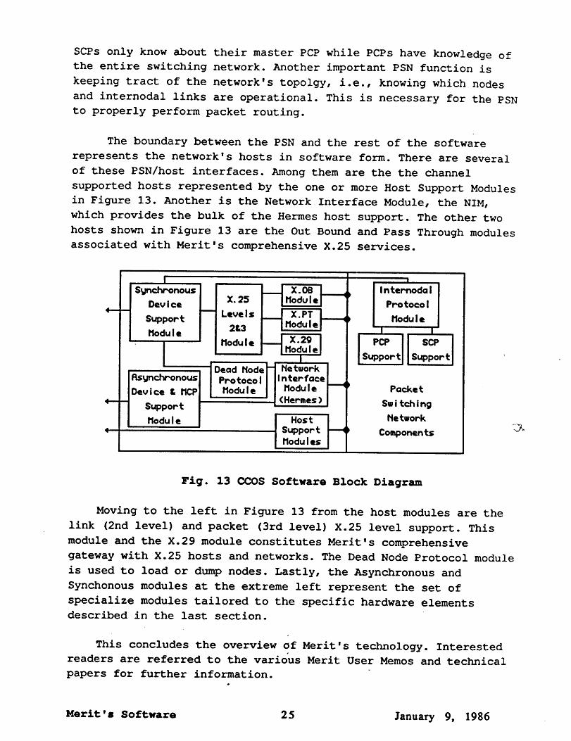
SCPs only know about their master PCP while PCPs have knowledge of
the entire switching network. Another important PSN function is
keeping tract of the network’s topolgy, i.e., knowing which nodes
and internodal links are operational. This is necessary for the PSN
to properly perform packet routing.
The boundary between the PSN and the rest of the software
represents the network’s hosts in software form. There are several
of these PSN/host interfaces. Among them are the the channel
supported hosts represented by the one or more Host Support Modules
in Figure 13. Another is the Network Interface Module, the NIM,
which provides the bulk of the Hermes host support. The other two
hosts shown in Figure 13 are the Out Bound and Pass Through modules
associated with Merit’s comprehensive X.25 services.
I
Dev I c:eSupportNodu I ¯
FIs~nch~onousDevice & NCP
Support
Nodule
~ X. 25-- Leve I s
2&3Nodu I ¯
IDead Node- NetworkPro toco I I n ter faceNodu I ¯ Nodu I ¯
(Hermes)
I X.OB ~IModuleI X.PTINodule~"-~
I X.29 IINodule
HostSupportNodules
i l nter~oda I
: ProtocolNodule ,
~ IPCP SCP
Suppor~ Support
PacketSwitchingNetwork
Co~ponents
Fig. 13 COOS Software Block Diagram
Moving to the left in Figure 13 from the host modules are the
link (2nd level) and packet (3rd level) X.25 level support.
module and the X.29 module constitutes Merit’ s comprehensive
gateway with X.25 hosts and networks. The Dead Node Protocol module
is used to load or dump nodes. Lastly, the Asynchronous and
Synchonous modules at the extreme left represent the set of
specialize modules tailored to the specific hardware elements
described in the last section.
This concludes the overview of Merit’s technology. Interested
readers are referred to the various Merit User Memos and technical
papers for further information.¯
Merit’s Software 25 January 9, |986

Appendix
This appendix contains supplemental information about the
network’s configuration. The following table lists each host and
identifies how it is attached. The column labelled Allowed Access
refers to whether a host can only open connections to the network,
Out Only, only receive them, In Only, or both, Bidirectional.
The series of diagrams after the table shows how the network’s
nodes are interconnected through the MMI6s. In these diagrams, one
or two for each of the network’s PCPs, the various shapes and
shadings signify classes of objects, e.g., SCPs appear as elongated,
unshaded ovals and the variously attached hosts as darkly shaded
rectangles. Each PCP’s network name appears in the big rectangle
left of center as do its MMI6 port numbers. Note, the inter-PCP
links are the partially shaded, rectangles. In these inter-PCp boxes
the number represents the MMI6 port number in the other, named PCP.
Host CPU Operating Network AllowedNetwork
~ ~ System ~ ~~
Channel Attached Hosts
MSU CL CYBER 750 SCOPE MSU-M CC Amdahl 5860 MTS UM
U-M CC Amdahl 470/V8 MTS
WMU ACC DEC i099 TOPS-10 WMWSU CSC Amdahl 470/V8 VM/MTS WU
WSU CSC IBM 3081 VM/MVS WS
Bidirectional
Bidirectional
Bidirectional
Bidirectional
Bidirectional
Bidirectional
Batch Only
EL
AB,AD
AE,AF
AN
AB,AF
AN
KZ
DA, DB
DT
DT
Appendix 2 6 January 9, 19 8 6
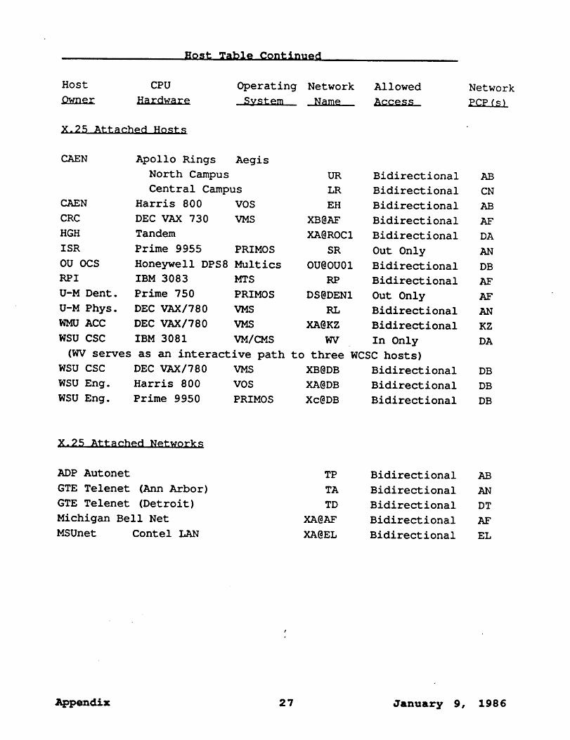
Host Table Contin~~d
Host CPU Operating Network
System _~
Allowed Network
X.25 Attached Hosts
CAEN Apollo Rings Aegis
North Campus URCentral Campus LR
CAEN Harris 800 VOS EHCRC DEC VAX 730 VMS XB@AFHGH Tandem XA@ROCIISR Prime 9955 PRIMOS SROU OCS Honeywell DPS8 Multics OU@OU01RPI IBM 3083 MTS RPU-M Dent. Prime 750 PRIMOS DS@DEN1U-M Phys. DEC VAX/780 VMS RLWMUACC DEC VAX/780 VMS XA@KZWSU CSC IBM 3081 VM/CMS WV
Bidirectional
Bidirectional
Bidirectional
Bidirectional
Bidirectional
Out Only
Bidirectional
Bidirectional
Out Only
Bidirectional
Bidirectional
In Only(WVserves as an interactive path to three WCSC hosts)
WSU CSC DEC VAX/780 VMS XB@DB BidirectionalWSU Eng. Harris 800 VOS XA@DB BidirectionalWSU Eng. Prime 9950 PRIMOS Xc@DB Bidirectional
AB
CN
AB
AF
DA
AN
DB
AF
AF
AN
KZ
DA
DB
DB
DB
X. 25 Attached Networks
ADP Autonet
GTE Telenet (Ann Arbor)
GTE Telenet (Detroit)
Michigan Bell Net
MSUnet Contel LAN
TP
TA
TD
XA@AF
XA@EL
Bidirectional AB
Bidirectional AN
Bidirectional DT
Bidirectional AF
Bidirectional EL
¯ ppendix 27 January 9, 1986
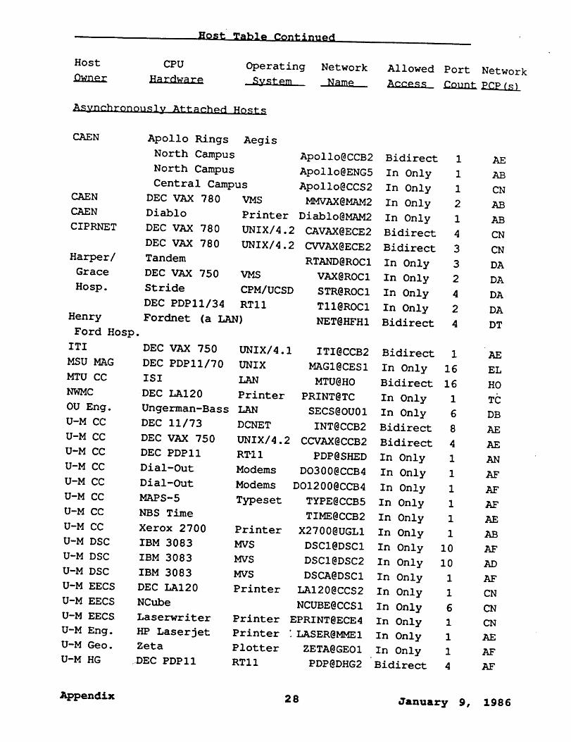
Host Table Continued
Host CPU Operating Network
System ~
Asynchronously Attached Hosts
Allowed Port Network
CAEN
CAEN
CAEN
CIPRNET
Harper/
Grace
Hosp.
Henry
Ford Hosp.
ITI
MSUMAG
MTU CC
NWMC
OU Eng.
U-M CC DEC 11/73U-M CC DEC VAX 750U-M CC DEC PDPII
U-M CC Dial-OutU-M CC Dial-OutU-M CC MAPS-5U-M CC NBS Time
U-M CC Xerox 2700U-M DSC IBM 3083U-M DSC IBM 3083U-M DSC IBM 3083U-M EECS DEC LAI20U-M EECS NCubeU-M EECS LaserwriterU-M Eng. HP Laserjet
U-M Geo. ZetaU-M HG :~DEC PDPII
Apollo Rings Aegis
North Campus
North Campus
Central Campus
DEC VAX 780
Diablo
DEC VAX 780
DEC VAX 780
Tandem
DEC VAX 750 VMS
Stride CPM/UCSDDEC PDPII/34 RTIIFordnet (a LAN)
ApolIo@CCB2 Bidirect 1ApolIo@ENG5 In Only 1ApolIo@CCS2 In Only 1
VMS MMVAX@MAM2 In Only 2Printer Diablo@MAM2 In Only 1UNIX/4.2 CAVAX@ECE2 Bidirect 4UNIX/4.2 CVVAX@ECE2 Bidirect 3
RTAND@ROCI In Only 3VAX@ROCI In Only 2STR@ROCl In Only 4TII@ROCI In Only 2NET@HFHI Bidirect 4
DEC VAX 750 UNIX/4.1 ITI@CCB2 Bidirect 1DEC PDPII/70 UNIX MAGI@CESI In Only 16ISI LAN MTU@HO Bidirect 16DEC LAI20 Printer PRINT@TC In Only 1Ungerman-Bass LAN SECS@OU01 In Only 6
DCNET INT@CCB2 Bidirect 8UNIX/4.2 CCVAX@CCB2 Bidirect 4RTII PDP@SHED In Only 1Modems DO300@CCB4 In Only 1Modems DOI200@CCB4 In Only 1Typeset TYPE@CCB5 In Only 1
TIME@CCB2 In Only 1Printer X2700@UGLI In OnlyMVS
MVS
1DSCI@DSCI In Only I0
DSCI@DSC2 In Only I0MVS DSCA@DSCl In OnlyPrinter LAI20@CCS2 In Only
NCUBE@CCSI In OnlyPrinter EPRINT@ECE4 In OnlyPrinter "LASER@MMEI In OnlyPlotter ZETA@GEOI In OnlyRTII
1
1
1
1
1PDP@DHG2 Bidirect 4
AE
AB
CN
AB
AB
CN
CN
DA
DA
DA
DA
DT
AE
EL
HO
DB
CN
Appendix 2 8 January 9, 19 8 6

Host Table Continued
Host CPU Operating Network Allowed Port Network
System --~ ~ ~ EE2_~
Asynchronously Attached Hosts Continued
U-M Lib. GEAC 1200 bps
U-M Lib. GEAC 300 bps
U-M Math R. Apollo
U-M SRL DEC VAX
U-M SRL HP Laserjet
WSU CSC Calcomp
WSU Chem. DG Eclipse S-130(1)
UMLIB@LIBI In Only
LIB300@LIBI In OnlyAegis AHAP@AH01 In Only
UNIX UNIX@STAT In Only
Printer LASER@STAT In Only
Plotter PLTR@WSI4 In Only
LCNI@WS05 In Only
8 AF
2 AF
1 AB
7 AN
1 AN
1 DT
1 DA
Appendix 2 9 January 9, 198 6

ADP
_ AUTON~
Amdahl 5860
Harris 800
Amdahl 470/V8
Apollo RirAegis
PCP Name: AB
PCP Location: U-M Computing Center
PCP Hardware: PDP 11/34, 2 MMI6s, 2 IBM Block Multiplexor Host I/Fs
Hermes Ports: None
Number of SCPs: 22
Number of X.25 Ports: 3
Number of Internodal Links: 3
Appendix 3 0 January 9, 19 8 6

CCB3
MAM2 DEC VAX 780
Diablo
Printer
NUB1
Math ReviewsApolloAegis
Xerox 2700
Printer
PCP Name: AB
PCP Location: U-M Computing Center
PCP Hardware: PDP 11/34, 2 MMI6s, 2 IBM Block Multiplexor Host I/Fs
Hermes Ports: NoneNumber of SCPs: 22 ~
Number of X.25 Ports: 3
Number of Internodal Links: 3
Appendix 31 January 9, 19 8 6

Amdahl 5860
PCP Name: AD
PCP Location: U-M Computing Center
PCP Hardware: .PDP 11/34, 2 MMI6, 1 IBM Byte Multiplexor Host I/F
Hermes Ports: None
Number of SCPs: 14 "
Number of X.25 Ports: None
Number of Internodal Links: 5
Appendi~ 3 2 Jan u a ry 9, 19 8 6

U-M/DSCIBM 3083
PCP Name: AD
PCP Location: U-M Computing Center
PCP Hardware: PDP 11/34, 2 MMI6,. 1 IBM Byte Multiplexor Host I/F
Hermes ports: None
Number of SCPs: 14
Number of X.25 Ports: None
Number of Internodal Links: 5
Appendix 3 3 January 9, 19 8 6
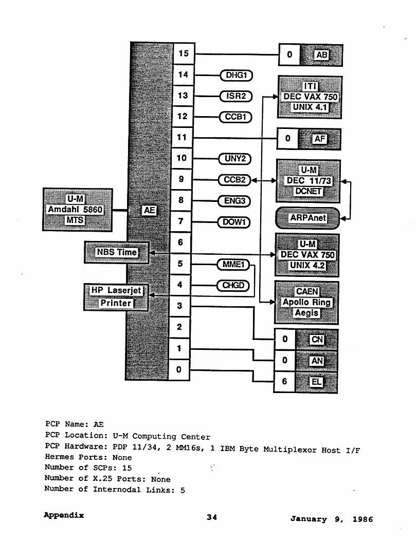
DEC VAX 750UNIX 4.1
Amdahl 5860
DEC 11/73~DCNET
~ ARPAnet_
NBS Time DEC VAX 750UNIX
HP Laserjet
Printer Apollo RinAegis
PCP Name: AE
PCP Location: U-M Computing Center
PCP Hardware: PDP 11/34, 2 MMI6s, 1 IBM Byte Multiplexor Host I/F
Hermes Ports: None
Number of SCPs: 15 :"
Number of X.25 Ports: None
Number of Internodal Links: 5
Appendil¢ 3 4 January 9, 19 8 6

BA06
BA04
PCP Name: AE
PCP Location: U-M Computing Center
PCP Hardware: PDP 11/34, 2 MMI6s, 1 IBM BYte Multiplexor Host I/F
Hermes Ports: None
Number of SCPs: 15
Number of X.25 Ports: None
Number of" Internodal Links: 5
Appendix 3 5 January 9, 19 8 6
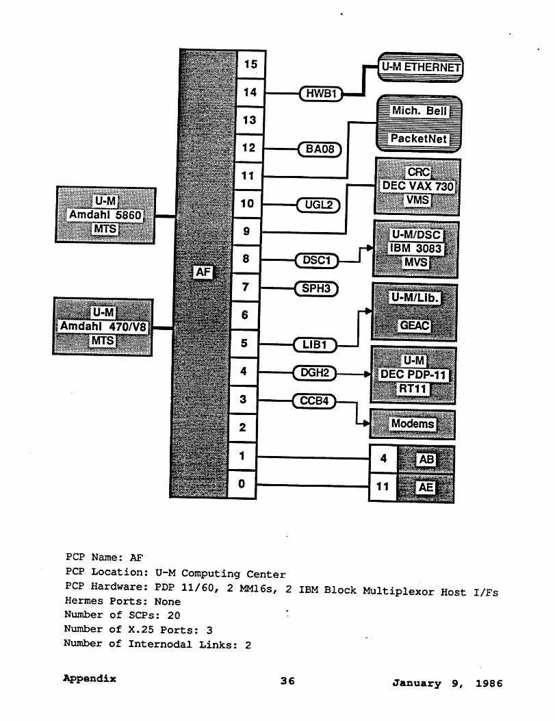
’Amdahl 5860
Amdahl 470/V8
U-M ETHERNET
_ Mich. Bell
_ PacketNet
DEC VAX 730
U-M/DSCIBM 3083
U-M/Lib.
DEC PDP-11
Modems
PCP Name: AF
PCP Location: U-M Computing Center
PCP Hardware: PDP 11/60, 2 MMI6s, 2 IBM Block Multiplexor Host I/Fs
Hermes Ports: None
Number of SCPs: 20 "
Number of X.25 Ports: 3
Number of Internodal Links: 2
Appendix 36 January 9, 1986

MAPS-5 PhotoTypesetter
U-M/Dent.Prime ~750
PRIMOS
IBM 3083
Plotter
PCP Name: AF
PCP Location: U-H Computing Center
PCP Hardware: PDP 11/60, 2 MM16s, 2 IBM Block Multiplexor Host I/Fs
Hermes Ports: None
Number of SCPs: 20
Number of X.25 Ports: 3
Number of Internodal Links: 2
Appendix 37 January 9, 1986

Amdahl 5860
Amdahl 470/V8
~ TELENET--
U-M/ISRPrime 750
U-M/P rDEC VAX 78(~
PCP Name: AN
PCP Location: U-M Computing Center
PCP Hardware: PDP 11/60, 2 MMI6s, 2 IBM Block Multiplexor Host I/Fs
Hermes Ports.-" None
Number of SCPs: 18 ;.
Number of X.25 Ports: 3
Number of Internodal Links: 3
Appendix 38 January 9, 1986

HP LaserjetPrinter
U-M/StatLabDEC
U-M/MeritDEC PDP-11
PCP Name: AN
PCP Location: U-M Computing Center
PCP Hardware: PDP 11/60, 2 MMI6s, 2 IBM Block Multiplexor Host I/Fs
Hermes Ports : None
Number of SCPs: 18 "
Number of X.25 Ports: 3
Number of Internodal Links: 3
Appendix 3 9 January 9, 19 8 6

PCP Name: CB
PCP Location: Cheboygan, Michigan
PCP Hardware: PDP 11/73, 2 KHVs
Hermes Ports: 8 Hardwired, 8 Dial-QpNumber of SCPs: None
Number of X.25 Ports: None
Number of Internodal Links: 2
Appendix40 January 9, 1986

CIPRNETDEC VAX 780s
UNIX 4.2
Apollo RingAegis
LaserwriterPrinter
Printer
Apollo RingAegis
NCube
PCP Name: CN
PCP Location: U-M’s East Engineering Building
PCP Hardware: PDP 11/60, 1 MMI6
Hermes Ports: None
Number of SCPs: 7 ~
Number of X.25 Ports: 1
Number of Internodal Links: 2
Appendix 41 January 9, 19 8 6
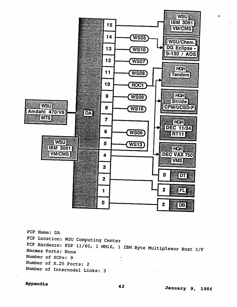
Amdahl 470/V8
30~VM/CM=
1
1
,
q
11
8
7
6
5
IBM 3081IS
WSU/Che=DG Ecli
30 / AO:
Tandem
PCP Name: DA
PCP Location: WSU Computing Center
PCP Hardware: PDP 11/60, 1 MMI6, i IBM Byte Multiplexor Host I/F
Hermes Ports .~ None
Number of SCPs: 9 ,Number of X.25 Ports: 2
Number of Internodal Links: 3-
Appendix42 January 9, 1986

WSU/Eng.Harris 800
WS02
Amdahl 470/V8 WSU/Eng.Prime 9950
PRIMOS
WSU/CSDEC VAX 780
PCP Name: DB
PCP Location: WSU Computing Center
PCP Hardware: PDP 11/60, 1 MMI6, 1 IBM Byte Multiplexor Host I/F
Hermes Ports: None ,Number of SCPs: 4
Number of X.25 Ports: 3
Number of Internodal Links: 3
Appendix 4 3 January 9, 198 6

Amdahl 470/V8
IBM 3081VM/CMS/MVS
Honeywell -DPS8/Multics
~ U-G LAN ~
GTE
~ TELEN
CalComPlotter
PCP Name: DT
PCP Location: WSU Computing Center
PCP Hardware: PDP 11/60, 1 MMI6, 2 IBM Byte Multiplexor Host I/Fs
Hermes Ports: None
Number of SCPs: 5 ""Number of X.25 Ports: 1
Number of Internodal Links: 3
Appendix 44 January 9, 1986
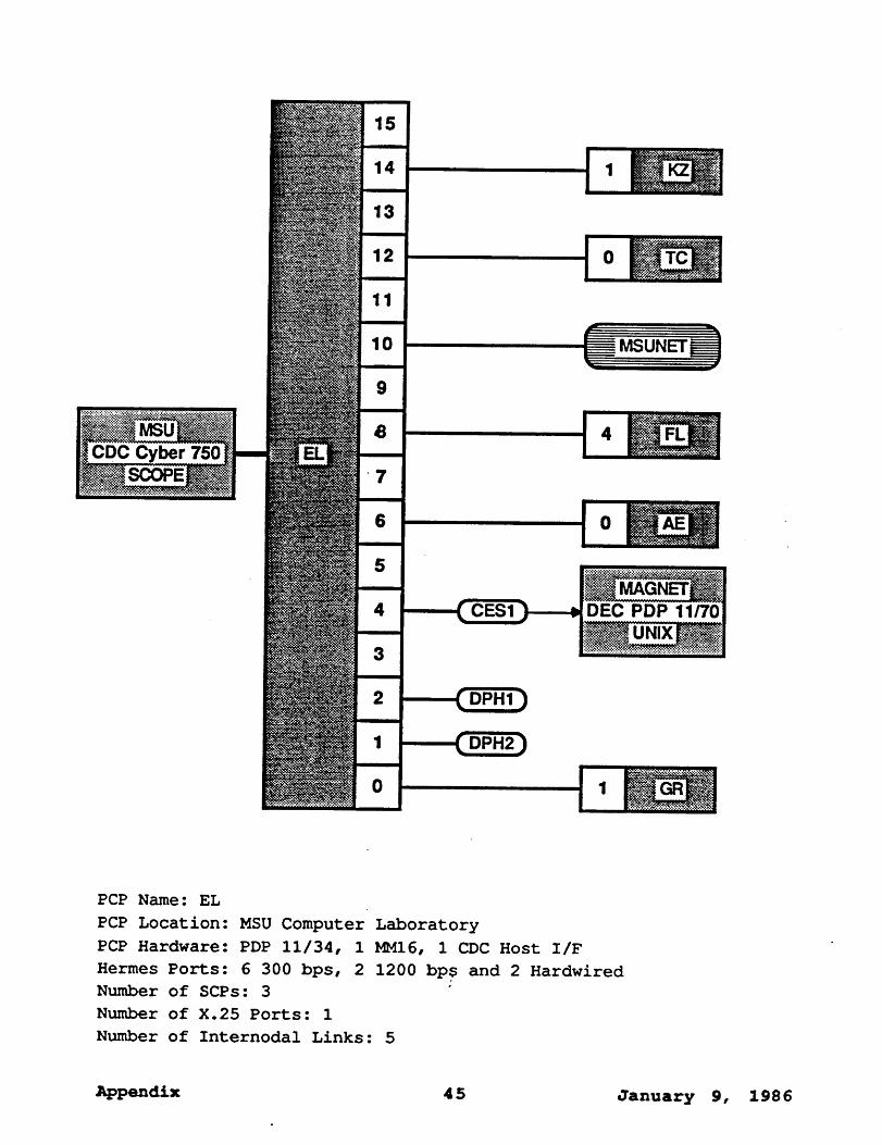
CDC Cyber 750
MAGNETDEC PDP 11/70
PCP Name: EL
PCP Location: MSU Computer Laboratory
PCP Hardware: PDP 11/34, 1 MMI6, 1 CDC Host I/FHermes Ports: 6 300 bps, 2 1200 bp$ and 2 Hardwired
Number of SCPs: 3
Number of X.25 Ports: 1
Number of Internodal Links: 5
Appendix 4 5 January 9, 19 8 6

PCP Name: FL
PCP Location: U-M/Flint
PCP Hardware: PDP ii/60, i MMI6
Hermes Ports: 13 Hardwired, 6 1200 bps
Number of SCPs: 2 ~,
Number of X.25 Ports: None
Number of Internodal Links: 2
Appendix46 January 9, 1986

PCP Name: GR
PCP Location: WMU Extension Center in Grand Rapids
PCP Hardware: PDP II/73, 3 KHVs
Hermes Ports: 16 Hardwired, 8 Dial-UP
Number of SCPs: None .
Number of X.25 Ports: None
Number of Internodal Links: 3
Appendix 4 7 January 9, 1986
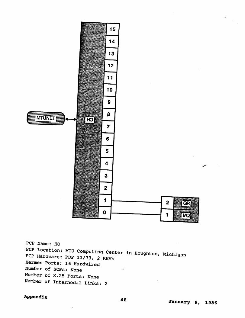
PCP Name: H0
PCP Location: MTU Computing Center in Houghton, Michigan
PCP Hardware: PDP 11/73, 2 KHVs
Hermes Ports: 16 Hardwired
Number of SCPs: None :,
Number of X.25 Ports: None
Number of Internodal Links: 2
Appendix48 January 9, 1986

WMUDEC 1099
PCP Name: KZ
PCP Location: WMU Computing Center
PCP Hardware: PDP 11/40, 1 MMI6, DEC DTE Host I/F
Hermes Ports: 8 Hardwired, 8 1200 .bps
Number of SCPs: None
Number of X.25 Ports: 1
Number of Internodal Links: 3
Appendix " 4 9 January g, 19 8 6
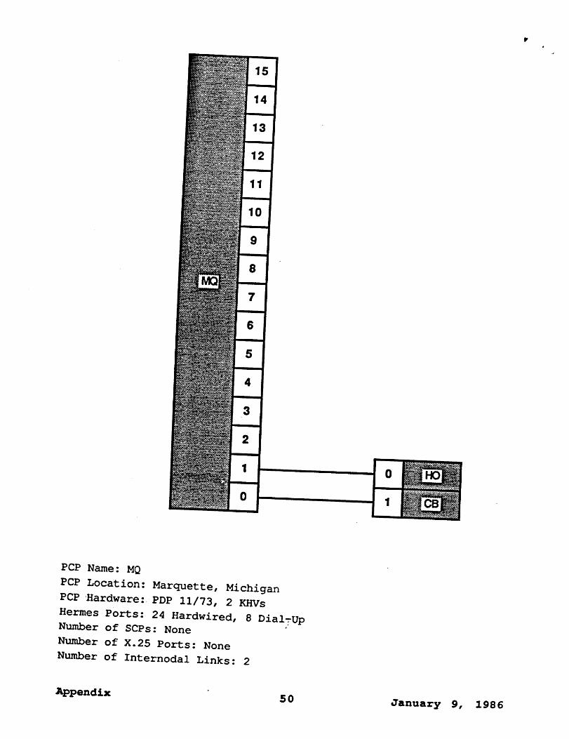
PCP Name: MQ
PCP Location: Marquette, Michigan
PCP Hardware: PDP 11/73, 2 KHVs
Hermes Ports: 24 Hardwired, 8 DialTUNumber of SCPs: None
Number of X.25 Ports: None
Number of Internodal Links: 2
Appendix50 January 9, 1986

PCP Name: OH
PCP Location: U-M/Dearborn Computing Center
PCP Hardware: PDP 11/60, 1 MMI6
Hermes Ports: 16 Hardwired
Number of SCPs: 2 :"
Number of X.25 Ports: None
Number of Internodal Links: 2
Appendix 51 January 9, 1986
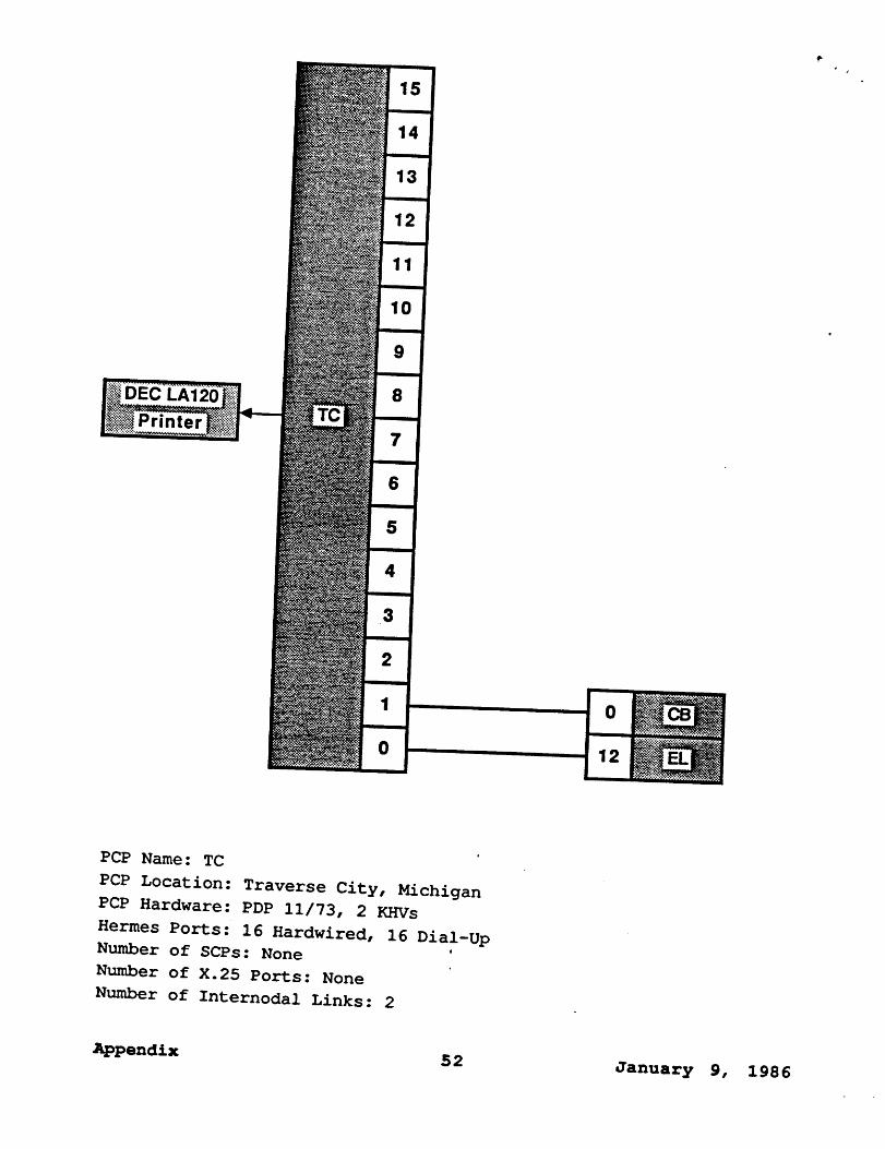
LA12~
PCP Name: TC ’
PCP Location: Traverse City, Michigan
PCP Hardware: PDP 11/73, 2 KHVs
Hermes Ports: 16 Hardwired, 16 Dial-Up
Number of SCPs: None ’
Number of X.25 Ports: None
Number of Internodal Links: 2
Appendix52
January 9, 1986


