N 7 J 16'15 3 NASA CR 72591 PROCESS DEVELOPMENT FOR A DISPERSION STRENGTHENED COBALT BASE ALLOY by Bernard H. Triffleman and Keki K. lrani CASE FILE Buffalo Facility prepared for NATIONAL AERONAUTICS AND SPACE ADMINISTRATION NASA Lewis Research Center . ' Contract NAS 3-1 1161 Fred H. Harf, Project Manager
Transcript
N 7 J 1 6 ' 1 5 3
NASA CR 72591
PROCESS DEVELOPMENT FOR A DISPERSION STRENGTHENED COBALT BASE ALLOY
by Bernard H. Triffleman and Keki K. lrani
CASE FILE
Buffalo Facility
prepared for
N A T I O N A L AERONAUTICS A N D SPACE A D M I N I S T R A T I O N
NASA Lewis Research Center . '
Contract NAS 3-1 1161 Fred H. Harf, Project Manager
Requests for copies of this report should be referred to
National Aeronautics and Space Administration Scientific and Technical Information Facility P.O. Box 33 College Park, Md. 20740
NOTICE
This report was prepared as an account of Government- sponsored work. Neither the United States, nor the National Aeronautics and Space Administration (NASA), nor any person acting on behalf of NASA:
A,) Makes any warranty or representation, expressed or implied, with respect to the accuracy, completeness, or usefulness of the information contained in this report, or that the use of any information, apparatus, method, or process disclosed in this report may not infringe privately-owned rights; or
B.) Assumes any liabilities with respect to the use of, or for damages resulting from the use of, any infor- mation, apparatus, method or process disclosed in this report.
As used above, "person acting on behalf of NASA" includes any employee or contractor of NASA, or employee of such contractor, to the extent that such employee or contractor of NASA or employee of such contractor prepares, disseminates, or provides access to any information pursuant to his employ- ment or contract with NASA, or his employment with such contractor.
NASA CR-72591
FINAL REPORT
PROCESS DEVELOPMENT FOR A DISPERSION
STRENGTHEWD COBALT BASE ALLOY
by
B e r n a r d R, T r i f f l e m a n and K e k i K. I r an i
CURTISS-WRIGET CORPORATION B u f f a l o Fac i l i ty
760 N o r t h l a n d A v e n u e B u f f a l o , New Y o r k 14215
p r e p a r e d f o r
NATIONAL AERONAUTICS AND SPACE ADMINI STRATION
D e c e m b e r 31, 1969
NASA L e w i s R e s e a r c h C e n t e r C l e v e l a n d , O h i o
Fred H. H a r f , Project M a n a g e r M a t e r i a l s and Structures D i v i s i o n
FOREWORD
This report was prepared by personnel of the Buffalo Facility of
the Curtiss-Wright Corporation, Buffalo, New York, and describes
original work performed under Contract NAS 3-11161.
The contract was awarded to Curtiss-Wright by the NASA-Lewis
Research Center. Technical monitoring was provided by the Project
Manager, Mr. Fred Harf, of the Materials and Structures Division of
the NASA-Lewis Research Center,
Bernard H. Triffleman of the Buffalo Facility served as the Curtiss-
Wright Project Manager; Keki K. Irani was Project Engineer,
Numerous Curtiss-Wright personnel contributed to the program, In
particular we wish to acknowledge the efforts of the following:
S. Allen, J. Bona, R. Crotty, D. Cress, D. Nalloran, D. Perry, E, Truhn,
F. C. Wagner, and G. G, Weart.
The electron metallography was performed under the direction o f
James L. McCall of Battelle Memorial Institute, Columbus, Ohio.
Additional and vital electron metallography was performed by
Mr. Bruno C. Buzek, Materials and Structures Division, NASA-Lewis
Research Center.
The contract work was performed over the period from June 25, 1968
to March 24, 1969.
ABSTRACT
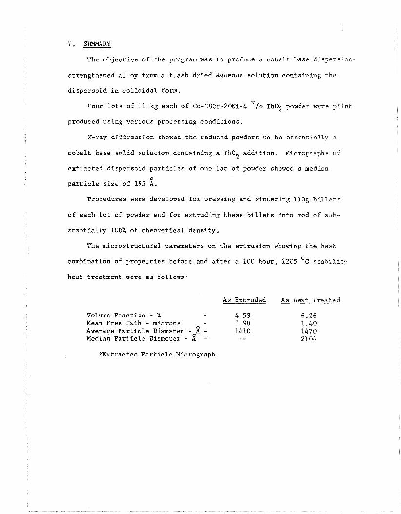
Co-18~r-20~i-b~/o Tho2 powders were prepared by the Flash Drying
Selective Reduction Process starting with an aqueous solution of metal
salts containing colloidal Tho Procedures were developed for prs - 2 '
cessing the powders into extruded rods of substantially 100% of theo-
retical density. The best procedure resulted in a rod containing a
0 median Tho size of 210 A after a 100 hour, 1205'~ stability heat
2
treatment.
I
I1
I11
I V
v
V I
V I I
V I I I
TABLE OF CONTENTS
SUMMARY
INTRODUCTION
PROCESS OUTLINE
PREPARATION OF OXIDES
REDUCTION PROCEDURES
CONSOLIDATION, E m R U S I O N AND EVALUATION
CONCLUSIONS
RECOMMENDAT IONS
A P P E N D I C I E S
APPENDIX I FORMULATION OF METAL SALT - COLLOIDAL THO2 SOLUTIONS
APPENDIX I1 AREAL AND LINEAL ANALYSES PROCEDURES
APPENDIX I11 EXTRACTION REPLICA MICROSCOPY
APPENDIX I V REPORT DPSTRPBUTION L I S T
LIST OF TABLES
No. - Results of X-ray and Topographical Analyses of Colloidal ThO Samples
2
Tho Crystallite Size and Phases Present in 2 Varlous Stages of Powder Production
Results of Reduci~g Ground Oxides Under Hydrogen at 1205 C for Various Time Periods
Chemical Analyses of Powders made by Four Procedures
Electron Diffraction Data on Tho Particles 2 Extracted from the Compacted and Densified Procedure A Powder
Results of Pressing, Sinterin~, and Extrusion Experiments on Co-l8Cr-20Ni-4 /o Tho Powders
2
Evaluation of Extruded and Heat Treated Rods of Co-18~r-20Ni-4~/0 TkO
2
Comparison of Spectographic Analyses of Powder and Extruded Rod No. 8
Electron Diffraction Data on Tho2 Particles Extracted from Procedure C and D Extrusions
LIST OF FIGURES
No. -
1. Step Chart Showing Manufacture of Alloy-Oxide Powders and Conversion into Extruded Rod
50-150 1 Size Colloidal Tho:, 0
108-300 A Size Colloidal Tho2 o
400-800 A Size Colloidal Tho2
Reduction Procedures for Alloy-Oxide Powders
Extracted Particles of Procedure A Powder
Extracted Particles of Procedure A Powder
Particle Size Distribution of the Tho2 Particles Extracted from the Compacted and;Densified Powder Sample
Procedures for Consolidation of Alloy-Bxide Powders
Cans for Test Extrusions
Curtiss-Wright Experimental Extrusion Steps
Vertical Extrusion Equipment
Photomicrograph of Extrusion No. 8 made from Procedure A Powder
Electronmicrograph of Extrusion No. 8 made from Procedure A Powder
Photomicrograph of Extrusion No. 12 made :from Procedure IS Powder
Electronmicrograph of Extrusion No. 12 made from Procedure B Powder
Photomicrograph of Extrusion No. 19 made from Procedure C Powder
Electronmicrograph of Extrusion No. 19 made from Procedure @ Powder
LIST OF FIGURES (Coni'd.)
No. - 19. Photomicrograph of Extrusion No:20 made from
Procedure D Powder
Electronmicrograph of Extrusion No. 20 made from Procedure D Powder
Electronmicrograph of Extracted Particles from Extrusion No. 8 made from Procedure A Powder
Particle Sfze Distribution of the Tho2 Particles Extracted from Extrusion No. 8
Extracted Particle Size Count, Ektrusion No. 8
Electronmicrograph of Extracted Particles from Extrusion No, 12 made from Procedure B Powder
Particle Size Distribution of the Tho2 Particles Extracted from Extrusion No. 12
Extracted Particle Size Count, Extrusion No. 8
Photomicrograph of Heat Treated Extrusion No. 8 made from Procedure A Powder
Electronmicrograph of Heat Treated Extrusion No. 8' made from Procedure A Powder
Photomicrograph of Heat Treated Extrusion No. 12 made frm Procedure B Powder
Electronmicrograph of Heat Treated Extrusion No. 12 made from Procedure B Powder
Photomicrograph of Heat Treated Extrusion No. 19 made from Procedure C Powder
Electronmierograph of Heat Treated Extrusion No. 19 made from Procedure C Powder
Photomicrograph of Heat Treated Extrusion No. 20 made from Procedure D Powder
Electronmicrograph of Heat Treated Extrusion No. 21 made from Procedure D Powder
No. - 35 *
LIST OF FIGURES (ConeB d.)
Paee No.
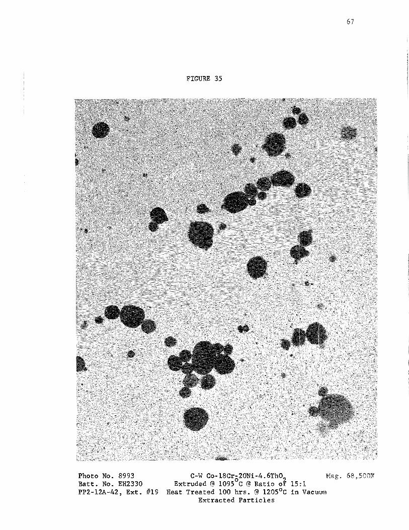
Electronmicrograph of Extracted Particles 6 7 from Heat Treated Extrusion No. 19
Electronmicrograph of Extracted Particles 6 8 from Heat Treated Extrusion No, 20
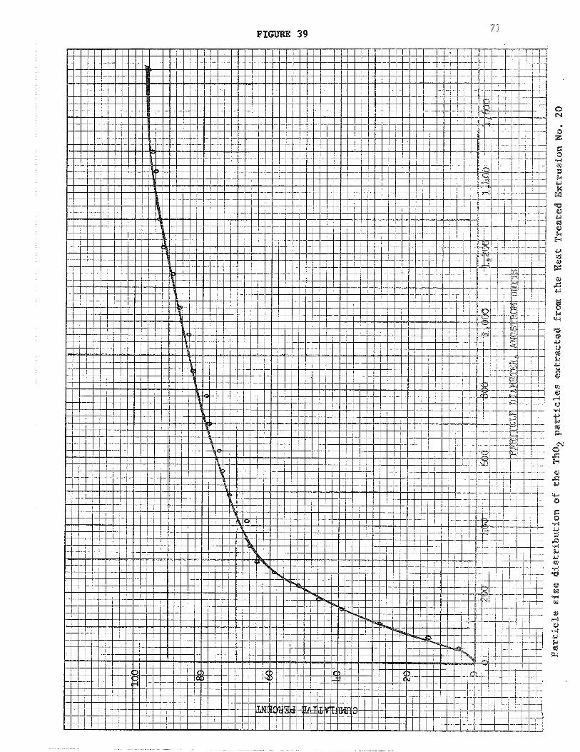
Particle Size Distribution of the Tho2 6 9 Particles Extracted frm the Heat Treated Extrusion No, 19
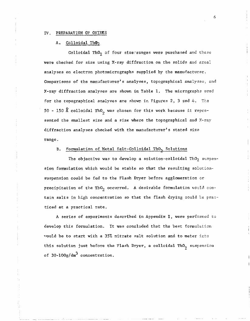
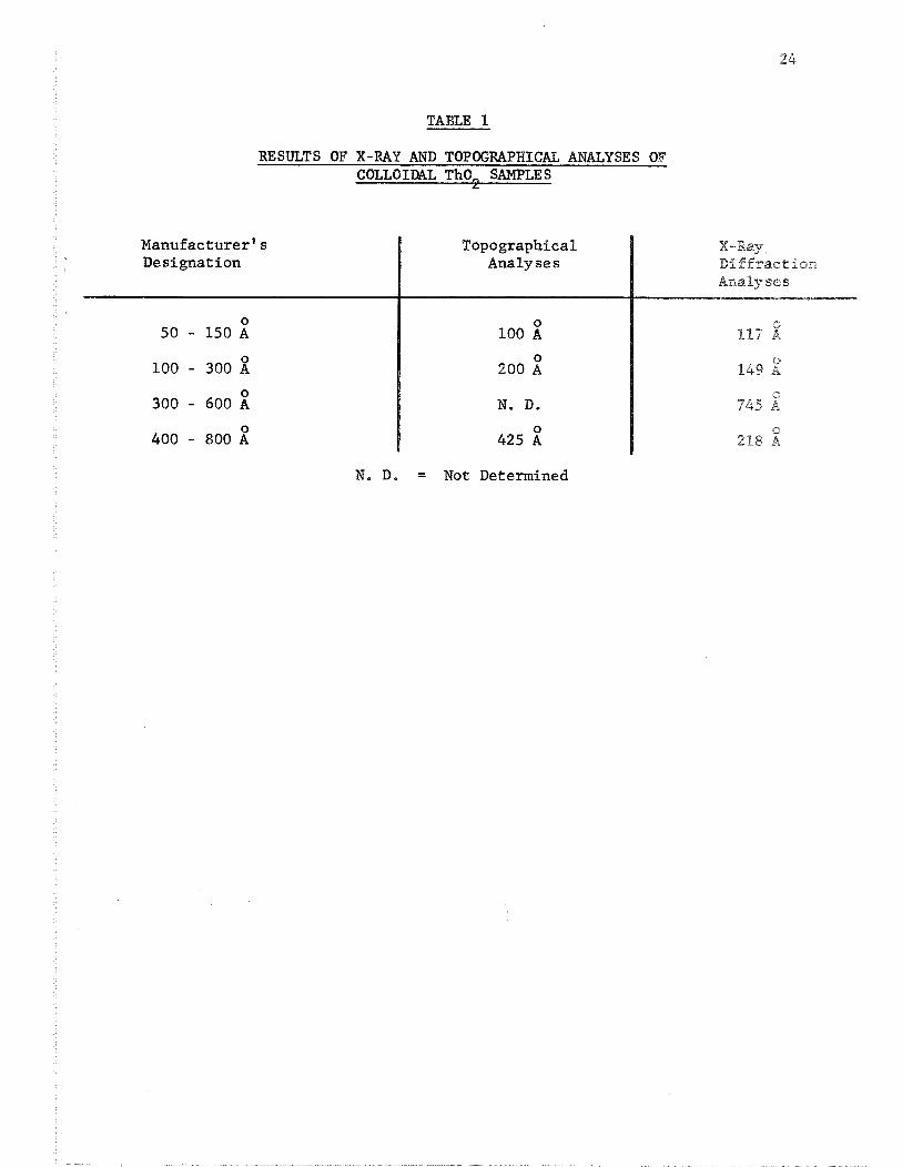
Colloidal Tho2 of four sizerranges were purchased and these
were checked for size using X-ray diffraction on the solids and areal
analyses on electron photomicrographs supplied by the manufactures,
Comparisons of the manufacturer's analyses, topographical analyses, and
X-ray diffraction analyses are shorn in Table 1. The micrographs used
for the topographical analyses are shown in Figures 2, 3 and 4. The
50 - 150 2 colloidal Tho was chosen for this work because <t repre- 2
sented the smallest size and a size where the topographical and X-ray
diffraction analyses checked with the manufacturer's stated size
range.
B. Formulation of Metal Salt-Colloidal. Tho, Solutions li
The objective was to develop a solution-colloidal Tho2 suspen-
sion formulation which would be stable so that the resulting siolmtion-
suspension could be fed to the Flash Dryer before agglomeration or
precipitation of the Tho2 occurred, A desirable formulation would eon-
tain salts in high concentration so that the flash drying could be prae-
ticed at a practical rate,
A series of experiments described in Appendix I, were perfomed to
develop this formulation, It was concluded that the best formulation
would be to start with a 35% nitrate salt solution and to meter into
this solution just before the Flash Dryer , a collofdal ThO suspension 2
3 of 30-100g/dm concentration.
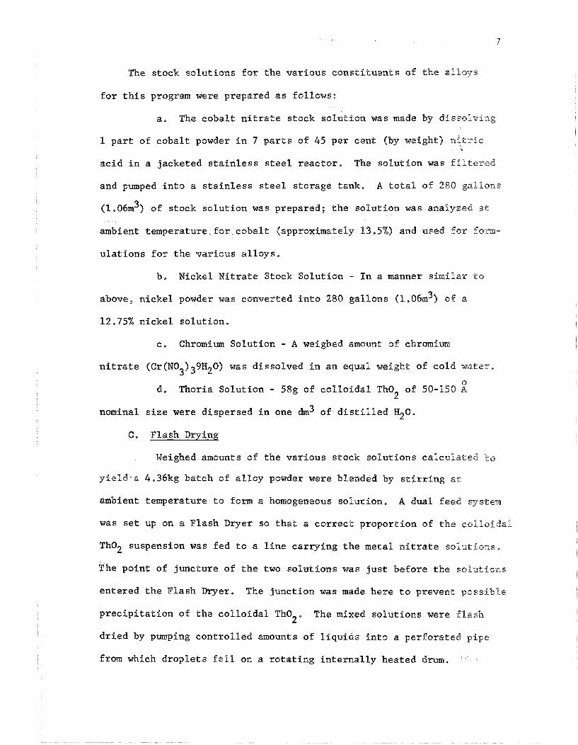
The stock solutions for the various constituents of the alloys
for this program were prepared as fallows:
a, The cobalt nitrate stock solution was made by dissolving
1 part of cobalt powder in 7 parts of 45 per cent (by weight) ni~ric
acid in a jacketed stainless steel reactor. The solution was filtered
and pumped into a stainless steel storage tank. A total sf 280 gallons
3 (1.06m ) of stock solution was prepared; the solution was analyzed at
ambient temperature,for cobalt (approximately 13.5%) and used for 5o.m-
ulations for the various alloys.
b, Nickel Nitrate Stock Solution - In a manner similar to above, nickel powder was converted into 280 gallons (l.06m3) o ~ f a
12.75% nickel solution.
c, Chromium Solution - A weighed amount of chromiumi nitrate (Cr(N0 ) 9H 0) was dissolved in an equal weight of cold water. 3 3 2
0 d. Thoria Solution - 58g of colloidal Tho2 of 50-150 A
nominal size were dispersed in one dm3 of distilled H20e
@. Flash Drying Weighed amounts of the various stock solutions calculated to
yie2d.a 4.36kg batch of alloy powder were blendcAd by stPrrfng at
ambient temperature to form a homogeneous solution, A dual feed system
was set up on a Flash Dryer so that a correct proportfon sf the eollofdal
Tho2 suspension was fed to a line carrying the metal nitrate solut$ons,
The point of juncture of the two solutions was just before the solutions
entered the Flash Dryer, The junction was made here to prevent possible
precipitation of the colloidal Tho The mixed solutions were flash 2 "
dried by pumping controlled amounts of liquids into a perforated p f p e
from which droplets fell om a rotating internally heated drum.
The drum was surrounded by a stainless steel housing and connected ta
an acid recovery system. The temperature of the drum was maintained
at 200 OC. The product was scraped off the drum by a stainless steel
"doctor blade".
Sufficient blended solutions were flash dried by the above
procedure to yield 43,6kg of alloy,
A chemical analysis of the Zlash dried material showed only
0,0037, nitrogen present. This indjiested that the deemposition of the
nitrate salts was substantially camp'hete,
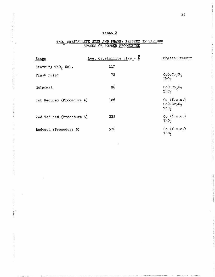
X-ray diffraction analyses for phases present and Tho2 particle
size were made and the results are shown in Table 2.
D. Calcination
The object of this step was to stabilize the Tho2 size,
Since the chemical analysis on the flash dried material indicated that
the evolution of the acid gases was practically complete, it was decided
not to calcine one 11 kg batch of powder (hereinafter referred to a s
Procedure A Powder) and to calcine the remainder. The powder was fed
into a rotary ealciner and heated at 400 'C for 15 minutes In air,
An X-ray diffraction study was made on this material and the result^
are shown in Table 2.
The powder from the Flash Dryer and Calciner is approximately 4
mesh and finer, Previous work by this contractor had shown that a - 50
mesh oxide powder is necessary for proper reduction and compactiofi 35 the
powder. The calcined powder was therefore ground in a hammer mill.
Substantially 100% recov@ry of - 50 mesh powder was obtained.
8. REDUCTION PROCEDURES
The object of the reduction procedures was to reduce the non-ThQ2
oxygen to a level of 0,03% or below without agglomerating the "PO2,
Four procedures were investigated and these are shown in step chart
form in Figure 5. The details of the procedures are given below:
First Reduction Procedures A, C, and D,
The object of the first reduction was to remove as much
oxygen in a comparatively short time and at a Pow temperature,
The reduction was carried out in a rotary caEciner for 20 minutes
at 925 OC. Procedure A powder was reduced under dissociated amonia
while Procedure C and D powders were reduced under hydrogen.
Due to some agglomeration of the powder during the reduction step,
it was necessary to regrind the powder to -50 mesh. This step was
done in a hammer mill,
A weight loss analysis showed the non-Tho2 oxygen content to be
6.16% on Procedure A material and 7.3% on Procedure C and D material,
A nitrogen analysis showed the Procedure A powder to contain 0,012%
N and Procedure C and D material to contain 0.003% N, Thus fit can be
seen that some nitrogen pickup occurs under dissociated ammonia,
An X-ray diffraction analysis on Proeedure A material is shorn in
Table 2,
Second Reduction Procedure A, C, and D,
At this point graphite sufficient to react with the oxygen
present was added. The objectives were non-Tho2 oxygen and carbon con-
tents of less than 0.03%. Procedure A powder was blended with 4,16%
graphite and Procedure C and D powder was blended with 5,4%% graphite,
I
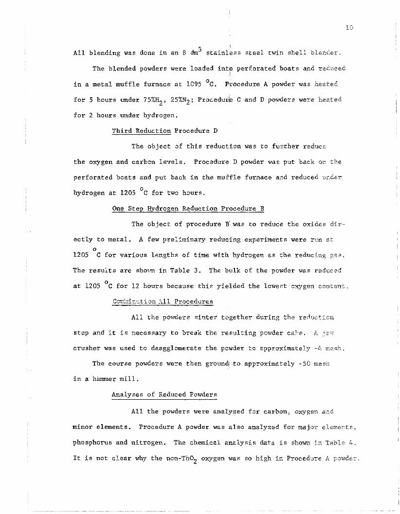
A l l blending was done i n an 8 dm3 s t a i n l e s s s t e e l twin s h e l l blender.
The blended powders were loaded f n t p perfora ted boats and reduced
i n a metal muffle furnace a t 1095 "c. Procedure A powder was heated
f o r 5 hours under 95%H2, 25%N2; Procedurie C and D powders were heated
f o r 2 hours under hydrogen.
Third Reduction Procedure D
The objec t of t h i s reduction was t o fu3ther reduce
t h e oxygen and carbon l e v e l s , Procediasre D powder was pent back: on the
perfora ted boats and put back i n t h e muffle furnace and reduced under
0 hydrogen a t 1205 C f o r two hours.
One Step Hydrogen Reduction Procedure B
The objec t of procedure B was t o reduce the oxides d i r -
e c t l y t o metal. A few preliminary reducing experiments were run a t 0
1205 C f o r var ious lengths of time with hydrogen a s t h e reducing gas ,
The r e s u l t s a r e shown in Table 3 , The bulk of the powder was reduced
0 a t 1205 C f o r 12 hours because t h i s yielded the lowest oxygen content .
@oir"C1-ir_c_izion ,111 Procedures
A l l t h e powders s i n t e r together during the reduction
s t ep and it i s necessary t o break t h e r e s u l t i n g powder cal*.e, A ;ax..
crusher was used t o deagglomerate t h e powder to approximately -4 mesh,
The course powders were then ground t o approximately -50 mesh
i n a hanuner m i l l ,
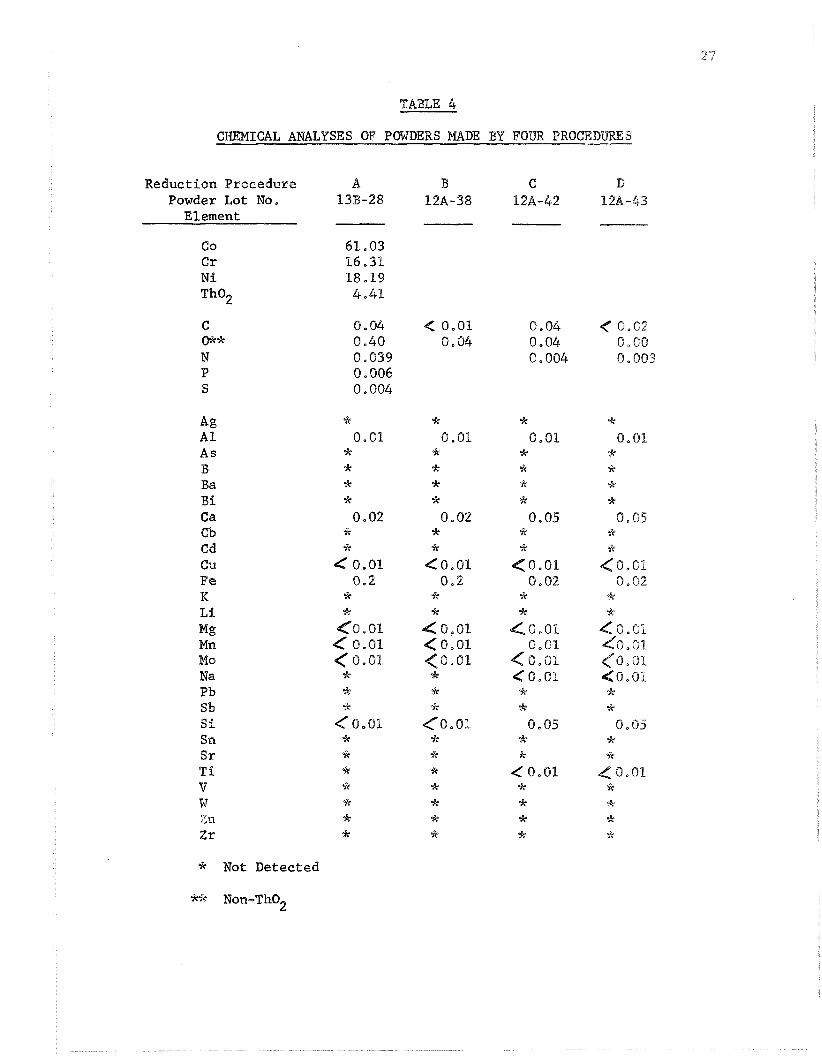
Analyses of Reduced Powders
A l l t h e powders were analyzed f o r carbon, oxygjen and
minor elements. Procedure A powder was a l s o analyzed f o r major elements,
phosphorus and ni t rogen, The chemical a n a l y s i s data i s shorn i n Table 4 ,
It i s not c l e a r why t h e non-Tho2 oxygen was so high i n Procedure A powder,
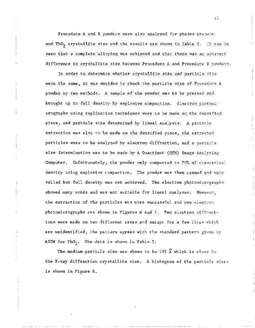
Procedure A and B powders were also analyzed for phases p re sen t
and ThQ2 cry-stallite size and the results are shown in Table 2, I lk can be
seen that a complete alloying was achieved and that there was an apparent
difference in crystallite size between Procedure A and Procedure B powder?,
In order to determine whether crystallite size and partiele size
were the same, it was decided to check the particle size of Procehre A
powder by two methods. A sample of the powder was to be pressed and
brought up to full density by explosive compaction. 'Electron photomi
crographs using replication techniques were to be made on the densiffed
pleee, and particle size determined by lineal analysis, A particle
extraction was also to be made on the densified piece, the extracted
particles were to be analyzed by electron diffraction, and a particle
size determination was to be made by A Quantimet QQm) Image AnaQyzlng
Computer. Unfortunately, the powder only compacted to 70% of theoretical
density using explosive compaction. The powder was then canned and warn.
rolled but full density was not achieved. The electron photo~nierographs
showed many voids and was not suitable for lineal analyses, B?owever,
the extraction of the partfeles was more successful and two eleeersn
photmierographs are shown in Figures 6 and 7. Two electron diFfraet -
ions were made on two different areas and except for a few 'Efnees which
are unfdentified, the pattern agrees with the standard patterra given by
ASTM for Tho2. The data is shom fn Table 5,
The medium particle size was shom to be 195 which is close to
the X-ray diffraction crystallfte size, A histogram of the particle s f z e s
is shown in Figure 8.
VI . CONSOLIDATION, EXTRUSION, AND EVALUATION
A. General
It has been found advantageous @ran previous work to press
and sinter billets and to extrude the resulting billets into rod, The
sintering of the billets removes the residual oxides in the powders,
Extruding pressed and sintered billets versus extruding loose powders
simplifies the can design. The extrusion cornpeetesthe densiffeation
of the sintered billets to substantially l'60% of theoretical density,
B. Sintering
Two consolidation procedures were used as shown in Figure 9,
Powders from Procedures B, C, and D reductions were low in
non-Tho oxygen and would be used without further reductions. Powder 2
from the Procedure A reduction was high in oxygen. Therefore in order
to use this powder, an additional reduction had to occurldu?ing the
sintering. An addition of graphite suffiefent to reduce it to 0,03%
maximum was made. Specifically each 2,25kg batch of Procedur~e A powder
was blended with 0.3 weight % graphite (99.9% C) in a twFn shl.11 4 dm3
stainless steel blender,
1.5" ( 3 , 8 cm) Q.D, x I,%'' ( 3 0 8 cm) long slugs were pressed of each
6 powder in a sprfng-loaded die on a 200 ton ( f , 8 x 16 R) hydraulic press,
2 Procedure A powder was pressed at 40 TSI (566 N / m 9 because it was
desired to have a billet dense enough for the carbon to diffuse evenly
and to react with the non-Tho2 oxygen.
Pressed billets of Procedures B, C , and D po~~ders were to be
sintered in a hydrogen atmosphere and therefore low density billets
were desirable for reaction of the oxides with the gas. The powders
2 were therefore pressed at 10 TSI (140 N / m 9,
The pressed slugs ware aintered at temperature^ and efmes show1
in Table 6, Sintering run Nos. l and 2 were made to study the effects
of temperature difference in sintering in vacuum, The higher sintering
temperature increased the density of the billets, drove the carbon-
oxygen reaction more to completion and did not increase the average
Tho2 crystallite size, Sintering run Nos. l and 3 were made to
study the effect of time differences in sintering in vacuum. The
longer sintering time did not increase the density of the billet but
seemed to have driven the carbon-oxygen reaction more to completion,
Sintering run Nos. 3 and 8 were made to study the effect of siratering
in vacuum and in dissociated ammonia (95% H2, 25% N2). Sintering Sn
dissociated ammonia did not increase the density of the billet as
much as in vacuum but apparently drove the carbon-oxygen reaction
more to completion. Sintering run Nos, 3 and 9 were made to study
the effect of sintering for 8 and 12 hours in vacuum. The ccwpara-
tively large increase in density in run No, 9 billet and non eompar-
ative chemical analyses can only be ascribed to the fact that a new
lot of powder was used in run No, 9. Run Nos. 1 and 10 were made to
study the effects of sfntering under the same conditions (2 k ~ u r ~
in vacuum) two lots of powder. Ifi9l.e the density of the billets were
the same, the carbon and oxygen analyses were not comparable. Whether
the difference in the carbon and oxygen analyses were due to differ-
ences in reactivity of two lots of powder or inaccuracies of chemical
analyses is not known at the present time, Sintering run Nos. 12 and
20 were made to study the effects of sintering different lots of powder
in hydrogen for 4 and 2 hours and at the same temperature, Fairly
comparative densities and chemistries were obtained. Sinterfng run
No. 19 was made to study the effect of sintering for 2 hours in
hydrogen at 1095 "c. The larger carbon and oxygen content o:f the
resulting billet when compared to run Nos. 12 and 20, can be ascribed
to the lower sintering tBmperature.
C. Extrusion of Billets
The billets from sintering run Nos. 8, 82, 19, and 20 were
canned in mild steel cans of dimensions shown in Figure 10 and the
cans were evacuated to one micron absolute pressure and sealed off,
The cans were heated for 30 minutes at temperatures indicated
6 in Table 6 and extruded on a 700 ton (6.2 x 10 N) press converted
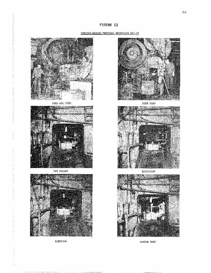
for small vertical extrusions, Figure 11 shows the appearance of
a sintered billet, canned slug, degassed and sealed can, and an
extruded specimen. Figure 12 shows the equipment and the steps
used in the vertical extrusion used for this work.
The extruded specimens were decanned with hot 50% nitric acid,
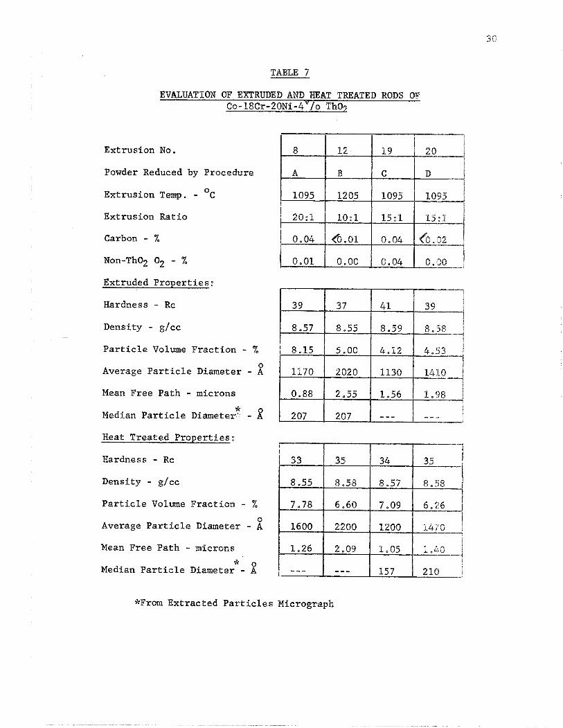
D. Evaluation of the Extrusions
The extruded rod was evaluated in the as extruded a.nd heat
o treated conditions. The heat treated rods were held at 1205 C for
- 4 100 hours in vacuum (10 torr). The purpose was to cheek the
stability of the microstructure by comparing the microstructure
parameters before and after the heat treatment. The evaluation eon-
sisted of the hardness and density cheeks (Table 7) and microstructural
examinations comparing the dispersoid parameters, types of precipitates
and void formation.
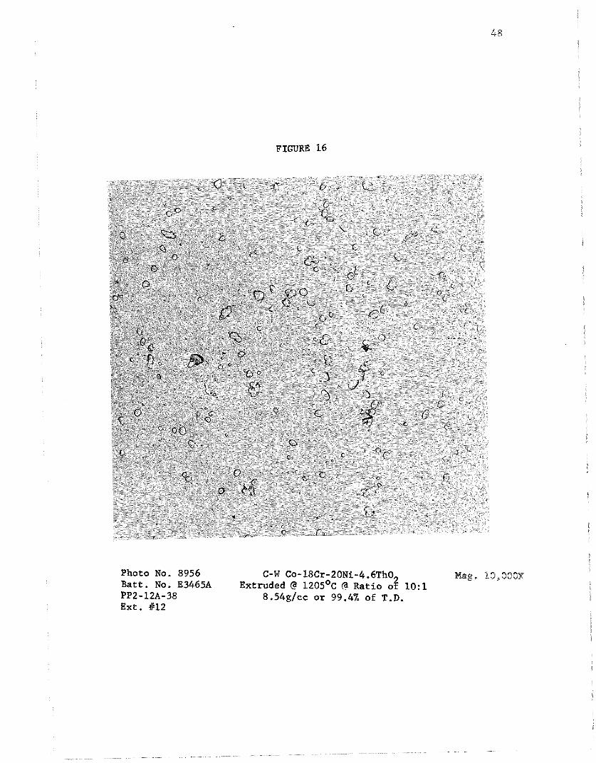
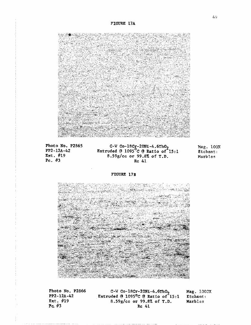
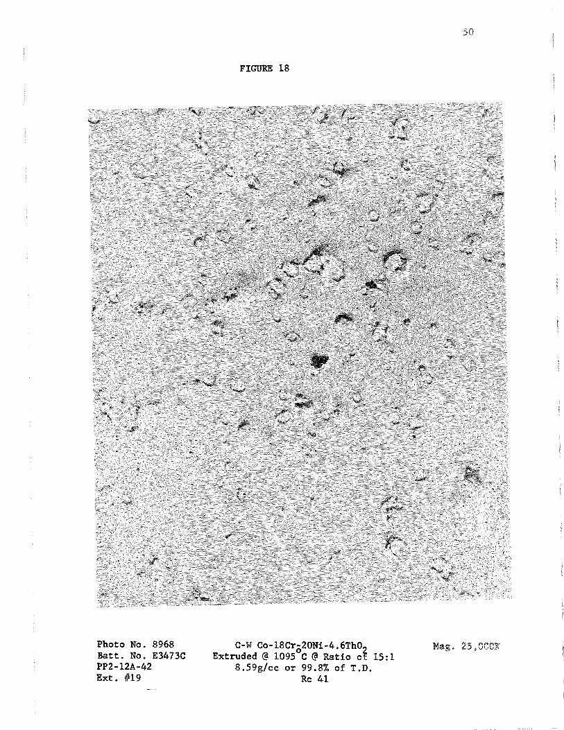
1. As Extruded Rods
Structures obtained by optical and replica electron
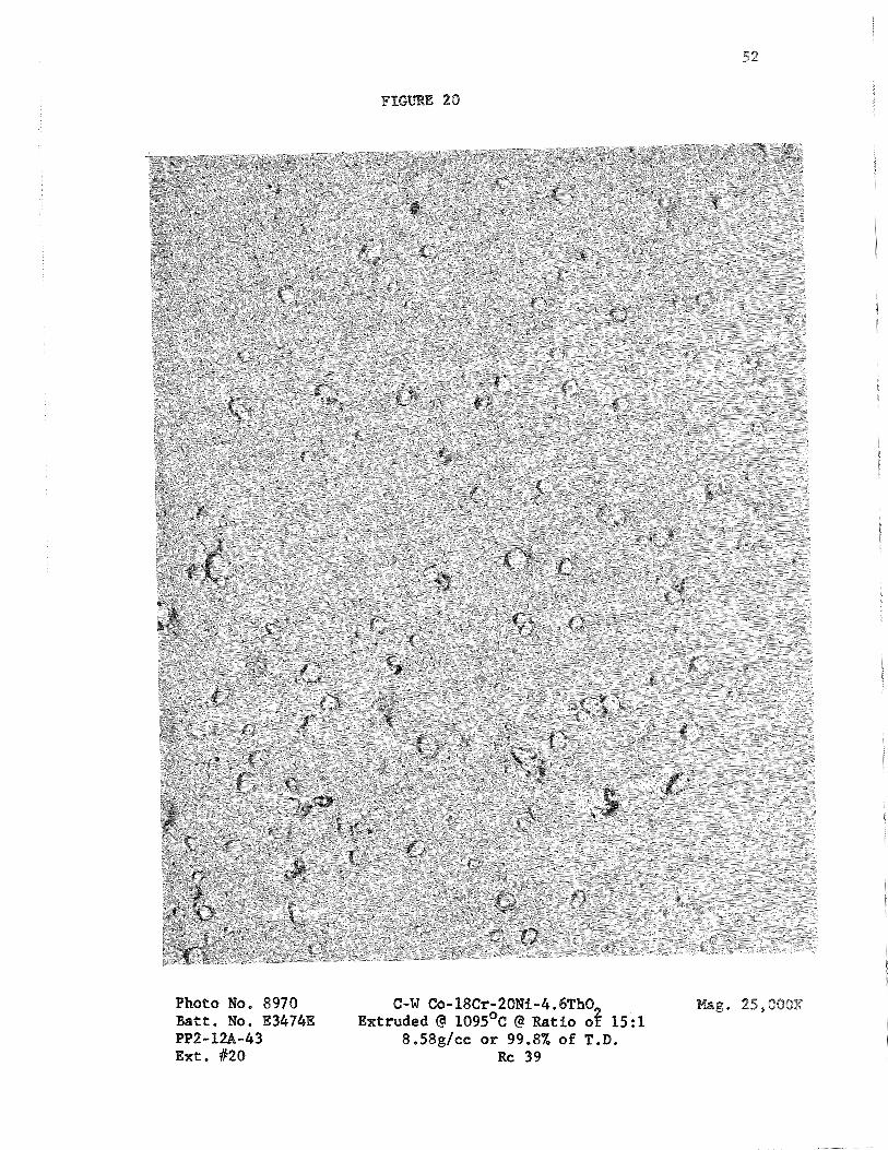
photomicrography are shown in Figures 13 through 20. Lineal analyses
were made on the electron micrographs and the results are presented
in Table 7,
The large volume percentage of dispersoLd in Extrusion
No. 8 was unexpected. Even if one is to assume that all the
non-Tho oxygen is tied up as Cr 0, and the carbon as Cr3C2Y the 2 2 2
volume fraction of the dispersoid would only be increased by a
maximum of 0.5%. A spectrographic analysis was made on this
extrusion and the result can be compared in Table 8 with the
spectrographic analysis of the powder. Same pickup of impurities
has taken place (probably in the blending step), but this still does
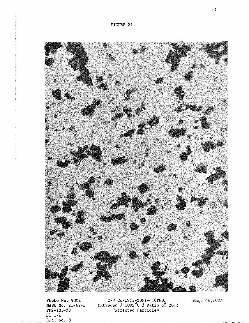
not account for the excess percentage of dispersoid. In order to
investigate anomalies found in the microstructure of this extrusion
more fully, an electron photomicrograph (Figure 21) was made on the
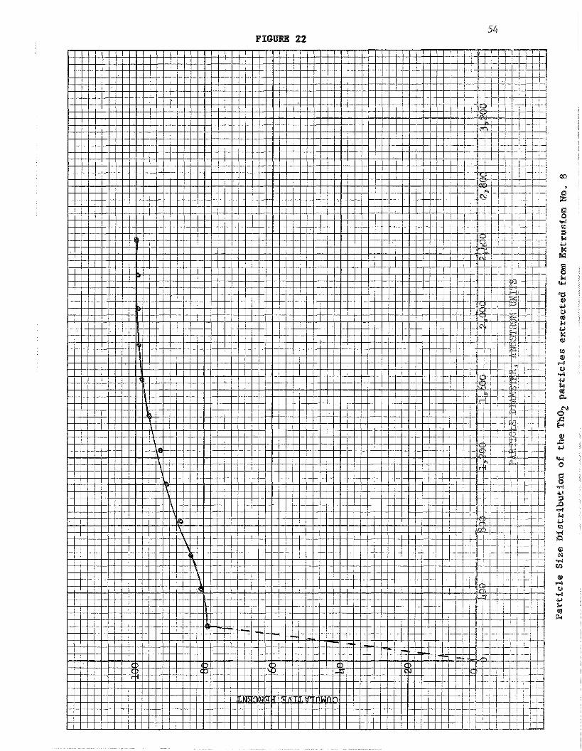
extracted particles. The size distribution of the particles was
0 plotted, (Figures 29. and 23). The median particle diameter o ~ f 207 A
0 compares favorably with the median particle diameter of 195 A
obtained in the powder sample,
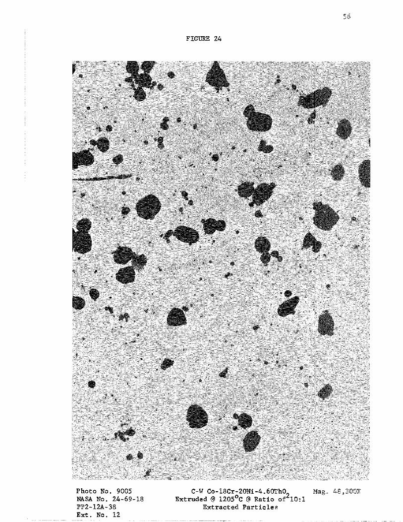
In Extrusion No. 12, the particle diameter obtained by
lineal analysis of replication electron photomicrographs is 2828 2 ,
Therefore, a particle extraction was also made on this extrusion
and an electron micrograph made of the particles. The micrograph
is shown in Figure 24. The median particle size was found to be
207 8, the size distribution of the particles are shown in Figures 25 and 26,
It was therefore concluded that the replica electron
micrographs were not giving an accurate picture of the particle
sizes.
2. Heat Treated Extrusions
Densities and hardness were measured on each rod and
can be seen in Table 7. The hardness dropped on each extrusion and
Extrusions 8 and 19 had the largest decrease, No explanation can be
given at this time for this hardness decrease. The density changes
were small for all extrusions and are probably within experiniental
error,
Optical photomicrographs and replica electron micrographs
were made on each heat treated sod and these are shown in Figures
27 through 34, It should be noted on the electron micrographs t h a t
no voids were formed, that no new phases precipitated and that the
dispersoids tended to spherodize, Lineal analyses made on the elee-
tron micrographs are shown in Table 7.
Since it was found on the extruded rods that surface
replica micrographs were not showing the smallest particles, elec-
tron micrographs were again made of the extracted particlea. Examples
of the resultant micrographs are shown in Figures 35 (Extrusion No, 19)
and 36 (Extrusion No, 2 0 ) . The median particle sizeswere found to be
0 157 and 210 A. The size distribution plots are shown in Figures
37 through 40 .
An additional set of extraction replicas on the same t w o
extrusions were obtained from NASA-Lewis Research Labs and these
are shown in Figures 41 and 4 2 . About 96% of the particles on each 0
micrograph are 217 A or below which is in fair agreement with the
median particle size determinations made in Pigures 35 and 36 ,
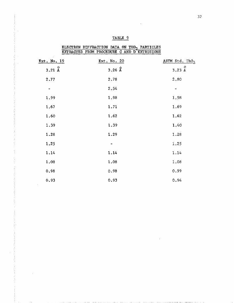
Ln Pigures 35 and 36 about 20% of the particles are larger
0 than 600 A and it was believed that these could be another phase,
An electron diffraction analysis was run on the extracted particles
and the data is shown in Table 9. The patterns appear to index
with the standard Tho2 pattern except that one point (2.54 61) is not
accounted for. From this data one might make the following assumptions:
1. The non-indexing of one point in the electron
diffraction is significant and some of the particles are of ~ m k n o w
phase.
2. The non-indexing of one point is not significant
and all the particles are Tho 2 *
If assumption 1 is made, then one may further assunre that
the unknown phase is either a mixed oxide of the matrix alloy metals
or a hard to reduce oxide picked up in one of the processing steps,
In the former case, it would be advantageous to sinter the pressed
billets in a can under very dry hydrogen to remove any matrix oxides
still not reduced. In the latter case, care should be taken not to
pick up any oxides in the processing equipment.
If one is to assume that all the large particles are Tho 2 "
then one should compare the particle size dtstribu&ws sf ch i s alloy
with those of other dispersion-strengthened alloys having impiroved
properties, Inman and Smith (PO) plotted the dispersoid size
distributions of a ~i-2"lo ThO alloy and found about 6% of the par- 0
2
ticles larger than 600 A. Raymond and Nemann (11) plotted the d i s -
persoid size distribution in two ~i-20~r-2"/0 ThO alloys made %y two 2
manufacturers and found that each alloy had at least 16% sf the 0
particles larger than 500 A and that some of the particles were up to
2000 2. It may therefore be inferred that in all oxide dispersoid
strengthened materials there is some growth of some of the particles
so that a stable size distribution results and this may be the reason
for the size distribution of the particles in this alloy.
Raymond and Nemann (11) also found that one sf the two
~ i - 2 0 ~ r - 2 ~ / 0 Tho alloys had better high temperature stability and 2
they attributed this to the difference in the average particle dia-
meter of the two products; the more stable material had an average
0 0 dispersoid diameter of 550 A compared to 820 A for the less stable
product. The average particle diameter of Extrusions 19 and 20
were calculated to be 349 and 455 2 respectively indicating that both.
these extrusions had sufficient fine particles to be effective in
strengthening the alloy at high temperatures.
VII . CONCLUSIONS
1. A ~ 0 - 1 8 ~ r - 2 0 N i - 4 ~ / 0 Tho2 a l l o y powder wi th acceptab le micro-
s t r u c t u r a l parameters can be produced us ing t h e P la sh Drying S e l e c t i v e
Reduction Process , Furthermore, t h i s a l l o y powder can be procesced
i n t o rod of s u b s t a n t i a l l y 100% of t h e o r e t i c a l dens i ty and having
accep tab le m i c r o s t r u c t u r a l parameters. The fol lowing process para-
meter? should be followed:
A. The s t a r t i n g soEutions should c o n s i s t of a c o l l o i d a l
suspension of 50-150 2 Tho of a concen t r a t ion of 3 0 - ~ 0 0 ~ / d m ~ and a 2
35% (by weight) s o l u t i o n of Co, C r , N i , n i t r a t e so lu t ions .
B. The c , i l l lo ida l Tho2 suspension and metal n i t r a t e s s l ~ ~ t ~ o n
should be mixed a t a po in t j u s t before both s o l u t i o n s e n t e r t h e Flash
Dryer.
C. The f l a s h dry ing should be done a t 200 OC.
D. The f l a s h d r i e d m a t e r i a l should be ca l c ined a t 4.00 '@
f o r 15 minutes .
E . The ca l c ined oxides should be ground t o minus 50 mesh, 0
F. The ground oxides should be f i r s t reduced a t 925 C f o r
20 minutes under hydrogen.
G. The f i r s t reduced m a t e r i a l should be blended w i t h . s u f f i c i e n t
h igh p u r i t y g raph i t e t o combine wi th t h e non ThO oxygen.
H. The blended m a t e r i a l should be second reduced a t 1095 "C
f o r 2 hours under hydrogen,
I. The second reduced m a t e r i a l shouPd be t h i r d reduced a t
0 1205 C f o r 2 hours under hydrogen.
J. The t h i r d reduced m a t e r i a l should be ground t o nninus 50
mesh .
2 c
K. The r e s u l t i n g powder should be pressed i n t o a bj.1Be.e
a t 10 TSI (140 l?/mm2)
L. The r e s u l t i n g b i l l e t should be s i n t e r e d under -tic '6:
0 hydrogen f o r 2 hours a t 1205 C.
M. The s i n t e r e d b i l l e t should be canned i n mild s t e e l and
evacuated t o 1 micron abso lu t e pressure .
N. The canned b i l l e t should be extruded a t a r a t i o of L O : l
0 a t 1095 6.
0. The extruded rod should be decanned i n 50% n i t r i c acid,
2. The a l l o y produced by t h i s method con ta ins Tho2 a s a f i n e d i s -
0 pe r s ion whi le t h e median s i z e of t h e d i spe r so id i s 210 A , (the ThO i~
2
p re sen t i n a range of s i z e s from 40 g t o 1500 8. It i s s o t c e r t a i n a t
t h e present t ime whether t h e l a r g e p a r t i c l e s a r e Tho2, unreduc:ed
ma t r ix oxides , o r some r e f r a c t o r y oxide picked up from t h e prcrcessing
equipment. It i s recommended t h a t precaut ionary measures be taken t o
prevent pickup of r e f r a c t o r y oxides by making su re a l l t h e process ing
equipment be cleaned p r f o r t o use and by d i sca rd ing t h e f i r s t f e w
pounds of powder going through each machine. It i s a l s o recoalmended
t h a t s i n t e r i n g of t h e p r e ~ s e d b i l l e t s be done i n s p e c i a l c l o s e f i t t i n g
cans under very dry hydrogen so t h a t any unreduced ma t r ix metal oxide?
may be converted t o meta l .
3 . It has been found t h a t reducing of t h e meta l powders and sint-
e r i n g of t h e pressed b i l l e t s under d i s s o c i a t e d ammonia (75% H,,, 25% T\J2) L.
t ends t o n i t r i d e t h e a l l o y due t o small amounts of undissoc ia ted amcnFa
l e f t i n t h e gas. Therefore, t h i s gas was found unsu i t ab l e for use i n
t h e process .
4 . The F l a s h Drying Sehecrive ReSa~c t ifi:la, Fs : t s e s ~ U s i n g
Tho, is suitable f o r making e t h e r disperc'sn-strengthened materi;-- F J L L - as Hi-Cr-Tho, , E.:L-Gr-W-ThB9, and Cs-Cu-Hi-Y-T%aO_ J 1 Brty T. - -
k
3 - 5. When the starring maeeriah for f lash d r y i n g uses c i L J ~ ~ ~ ~ J I
fine thoria, the particle size of the thor ia i n the eonscliazrec ar.3
extruded a l l o y approximates that of the co1Lvid, P a r t i c l e sl.zr .i&
thus predetermined. Th-is represents a defsaite advantage OVPB ~ T - C = E S & - where thor ia particles are formed by nucleation and growth q 6 i + : W I - s
a t t empted i n previous wcrk f o r f lash d r y i n g from s l a o ~ n o ~ e f i e i " ~ ~ n- txa l .n
solution (4) .
V I i L RECO~NDATIONS
1. A program should be initiated to determine fully the proper-
ties of the Co-l8Cr-20~1i-4~/o TRO allcry produced frm powder obtained 2
by the Procedure D reduction method, The alloy should be given suftabLe
thermal and mechanical working to optimize its properties.
2. The following two alloys should be prepared and the
properties be determined and optfmized by a property improvement pro-
gram :
(a) @o-20Cr-PUi%-PSW-2PhO 2
(b) Ni-18Cr-SMs-24Fe-4ThO 2
The cobalt base alloy is a modification of alloy L-605, The
base alloy co~nbines good formability and exeeffent high temperature
properties and has been used f o r many years in jzt engine p a r t s and
industrial furnace applications, The alloy is resistant to oxldatfon
o and carburizatfon to 1900 @. Dispersion strengthening may improve the high temperature scrength to the BTASA goals,
The nickel base alloy Is a modification s f Inconel 718, Tke base
alloy exhibits gocsd mechanical and fabri.;s.tion properties a t bokk-n
high and low temperatures and has excellent resistance to sulfuriza-
tion. This alloy ks nomally hardened by precipitation of Hi Cb, 3
Substiterting "rhO for the colaunbim may improve the high temperature 2
strength to NASA goals.
REFERENCES
R. C. Nelson and R. Widmer, "Development of Dispersion-StrengthenedP Nickel-Molybdenum, Nonoxidatisn-Resistant Allogp~.~' RASA Report CR-54502, April, 1967.
R. Grierson, L. J. Bonis, R. Rogers and 24. E. Livingston, "The Development of Dispersion-Strengthened blickel Chromium Oxidatifon Resistant Alloys." NASA Report CR 54523, July, 1966.
H. M. McCullough and M. Brtner, "DeveQopmeat of a Dispersion Strengthened Nickel Base Alloy Using the High 1ntensit:y Are Process ." NASA Report CR-54520. B. IE. Triffleman, "Development of Procedures for Prodwcing Disper- sion-Strengthened Cobalt Base Alloys by the Flesh Drying Selective Reduction Process." NASA Report CR-54516, December, 1967,
R. P. Cheney and W. Scheithauer, "Development of Cobalt Base Dis- persion-Strengthened Alloys." NASA Report CR-54599, December, 195R,
M. Gensamer, W, So Pellini and J. R. Low, ""P"nsile Properties of PearPite, Bainite and Spheroidite," Trans. Am. Soe. Metals, 30, 983 (1942) . -
M. Gensamer, "Strength and hctility," Trans. Am, Soe, HetaPs, 36, 30 (1946). - F. V. Lenel and G. S. Ansell, "Powder Metallurgy," Edjited by Werner Leszynski, Interscience Publishers.
A. E . Nineher, sPWesearch on Di spersf on Strengthened Cotsalt Base Alloys." Air Force Materials Laboratory Technical Reperrt A p i a - T R 65-442, Part 2, March, 1967.
N. e. %man and P. J. Smith, v'Ckfde Dispersion StrengtEnanPngqB9 G , S. Ansell et al, editors, Gordon and Breach Science PubPfshers, New York, 1968, p. 291,
L. Raymond and J. P. Nemann, International Journal of Powder Metallurgy, 2, No. 2, 97, (19691.
TABLE 1
RESULTS OF X-MY AND TOPOGRAPHICAL ANALYSES (9F
COLLOIDAL Tho, SAMPLE S L.
Manufacturer' s Topographical Designation Diffraction
0 50 - 150 A 0
117 A
100 - 300
300 - 600 0 745 A
400 - 800 2 N. D. = Not Determined
TABLE 2
Tho, CRYSTALLITE SIZE AND PHASES PRESENT I N VARIOUS - STAGES OF POWDER PRODUCTION
Stage
S t a r t i n g Tho2 Sol .
F l a sh Dried
Calcined
1st Reduced (Procedure A)
2nd Reduced (Procedure A)
Reduced (Procedure B)
0 Ave. C r y s t a l l i t e S i z e - A
117
78
Phases Present -
TABLE 3
TIME - HOURS
2
4
8
1 2
RESULTS OF REDUCING GROTJND OXIDES UNDER JXYDROGEN AT 1 2 0 s a e FOR VARIOUS TIME PERHODS
REUWKS --
Powder Pyrsphs r i e
Powder Pyropasric
Powder Stable
Powder Stable
CHEMICAL ANALYSES OF POWDERS MADE BY POUR PROCEDURES
Reduction Procedure A B C D Powder Lot No. 13B-28 P2A-38 128-42 1%-43
- Element --
%i.
0.01 9c
9e
9c
>b
0.05 9c
S":
QO.CPI 0.02
'k
90c
&s,on do. CIP ( o b o e <S.Cll 9c
9e
0.05 9e
* g 0.on * 9nr
9%
.pe
* Not Detected
TABLE 5
ELECTRON DIFFMCTHON DATA FOR THO9 PARTICLES EmRACTEI? FROM TEE COMPACTED AND DENSIPHED P R O C E D ~ E A POWDER
N o , f '1 0
3-26 8, 3,PO
No. 2
Ei a " e r E @ H Q) O m k
N e9 d 0
I a, I eA
I C g
I a R m m u a,
"3 .I-r 0
C @ , . g Z oa, g z u 2 5 &
-d u 2 E-l P m a u w m a " ~ o * J ~ - i a3
a " 3 O a G W W W oC P:a C O G & 'd -ri 0 ' B $ 5 . . 5 I
0 8
k M I k O k O ) k k k I k C C U r n u , ow kh .ri *d 7 a k a c o C a a a
w ~ a h a m a , u u u 2 X ? a 3 C u 3 3 : a c c
k .rl .d -5 .2 k G o N : fi S X 9 C
TABLE 7
EVALUATION OF EXTRUDED AND HIEAT TREATED RODS OF ~0-18Cr-20Ni-4"/0 Tho?
Extrusion No.
Powder Reduced by Procedure
0 Extrusion Temp. - C
Extrusion Ratio
Carbon - %
Non-Tho2 O2 - %
Extruded Properties:
Hardness - Re
Density - g/cc
Particle Volume Fraction - %
0 Average Particle Diameter - A Mean Free Path - microns
* Median Particle Diameted - 8 I 2 07 207 --- Heat Treated Properties:
4. Second Reduction C 7 5 H 2 , 4 , Second Reduction +- H2 25N2 t o 0.03% O2 t o 0,05% O2
B ONE STEP HYDROGEN REDUCTION D THREE STEP HYDROGEN PROCEDURE REDUCTION PROCEDURE
Reduce t o <-H2 1. F i r s t Reduction t- H2 0.03% O2 t o 6% 02
2. Grinding
3 , Blending <-. Graphf te
4. Second Reduction *- B2 t o 0,05% O2
5. Thi rd Reduction <-, B2 t o 0.00% O2
FIGURE 6
Photo No. 8958 C-W Co-18Cr-20Ni-4.6Th02 Mag, 150,000Y Batt. No. EH2172 Explosively Compacted and Hot Rolled PP2-12A-29 Extracted Particles
Photo No. 8957 C-W Co-18Cr-20Ni4.6Th02 Hag, 150,000X Batt. No. EN2173 Explosively Compacted and Not Rolled PP2-12A-29 Extracted Particles
FIGURE 9
PROCEDURES FOR CONSOLIDATION OF ALLOY-OXIDE POWDERS
I. High 0, Content Powder II. Low 02 Content Powder
1. Blend Graphite 1. ---
2. Press at 40 TSI (560 ~ / r n m ~ ) 2. Press at P O TSI (140 N j m 2 )
3. Sinter Under Vacuum and 3. Sinter Under H2 Dissociated Ammonia - r ~ r ' T \ 1:
(75% H2, 25% N2)
5. Can Billets
6. Extrude to Rod
7. Decan Rod
8. Evaluate Rod
9. Heat Treat Rod
10, Evaluate Heat Treated Rod
FIGURE 10 CANS FOR TEST EXTRUSIONS
MATERIAL : LOW CARBON COLD DRAWN SEAMLESS MECHANICAL TUBING COLD ROLL STEEL FOR END PLATES
FIGURE 11
CURTISS-WRIGHT EXPERIMENTAL EXTRUSION STEPS
(1) S i n t e r e d B i l l e t (2) Canned B i l l e t S e c t i o n (3) Canned and Degassed B i l l e t (4) Extruded Sample
FIGURE 12
CURTISS-WRIGHT VERTICAL EXTRUSION SET-UP
OVER ALL VIEW SIDE VIEW
HOT BILLET EXTRUSION
EJECTION SAMPLE PART
FIGURE 13A
Photo No. P2739 CW Co-18Cr-20Ni-4.6Th02 Mag. 2 0 0 O X PP2-13B-28 Extruded @ 20:l Ratio Une t c h e d B1 1-1, Ext. #8 8 . 5 7 g l c c or 99.64% of T.D.
Rc 39
FIGURE 13B
Photo No. P2741 CW Co-18Cr-20Ni-4.6Th02 Mag. :200(BX PP2-13B-28 Extruded @ 20:l Ratio Etchamt : B1 1-1, Ext. #8 8.57g/cc or 99.64% of T.D. Marbl~ea
Rc 39
Photo No. 8907 C-W Co-18Cr-20Ni4.6ThO li4ag, 20,000X Batt. No. G3443G Extruded at 1 0 9 5 ~ ~ at ~ a t i 8 of 20:l PP2-13B-28 8.57g/cc or 99.64% of T.D. BL 1-1, Ext. #8 Rc 39
Photo No. P2757 Co-18Cr-20Ni-4.6Th0 mg. lOOlDX PP2-12A-38 ~xttuded C 10: 1 @ 12030~ Etchant : Ext. #12 99.49, of T .D. (8.60g/cc=100%) Marbles
Rc 37
FIGURE 16
Photo No. 8956 C-W Co-18Cr-20Ni-4.6Th0 M<ag. 10,OOOX Batt. No. E3465A Extruded @ 1 2 0 5 ~ ~ @ Ratio of 10:l PP2-12A-38 8.54g/cc or 99.499 of T.D. Ext . /I12
Photo NO. P2865 C-W CO-18Cg-20Ni-4 .6Th02 M[ag, l(b0X PB2-12A-42 Extruded @ 1095 C @ Ratio of 15:1 Etchant : Ext . $19 8.59g/cc or 99.8% of T.D. Marbles PC. 1/3 Rc 41
FIGURE 17B
Photo No. P2866 C-W Co-18Cr-20Ni-4.6Th02 Mag. 100QBX PP2-12A-42 Extruded @ 1 0 9 5 ~ ~ @ Ratio of 15: 1 Etchant: Ext . 1/19 8.59g/cc or 99.8% of T.D. Marbles PC 1j3 Rc 41
Photo No. 8968 C-W Co-18CrG20Ni-4.6Th0 $
Hag, 25,000X Bate. No. E3473C Extruded @ 1095 C @ Ratio o 15:l PP2-12A-42 8.59g/cc or 99.8% of T.D. Ext. ill9 Rc 41
Photo No. P2870 C-I4 Co-18Cr-20Ni-4.6Th02 Mag, 100X PP2-12A-43 Extruded @ 1 0 9 5 ~ ~ @ Ratio of 15: 1 Etchant : Ext. #20 8.58g/cc or 99.8% of T.D. Marbles PC. 15 Rc 39
FIGURE 19B
Photo No. P2871 C-w Co-18Cg-20Ni-4.6Th02 Mag, 1080X PP2-12A-43 Extruded @ 1095 C @ Ratio of 15:l Etchcent : Ext . 7'120 8.58gIcc or 99.8% of T.D. Marbles PC. #5 Rc 39
Photo No. 8970 C-W Co-18Cr-20Nf-4.6Th0 Mag, 25,OOOX Batt. No. E3474E Extruded @ 1 0 9 5 ~ ~ @ Ratio o? 15:l PP2-12A-43 8.58gIcc or 99.8% of T . D . Ext. #20 Rc 39
Photo No. 9002 C-W Co-18Cr620Ni-4.6Th0 Elag. 48,OOOX NASA No. 21-69-5 Extruded @ 1095 C @ Ratio o$ 20: 1 PP2-13B-28 Extracted Particles B1 1-1 Ext. No. 8
5 5 FIGURE 23
0;)
0
0 zz F: 0 TI
3 k & X
F23 4
2 0 U
a, N d @3 a, rl 0
2 6d PI
% -4=' 0 a k & X W
Photo No. 9005 C-W Co-18Cr-20Ni-4.60Th02 1Yag , 48,300X NASA No. 24-69-18 Extruded @ 1 2 0 5 ~ ~ @ Ratio of 10:l PP2-12A-38 Extracted Particles Ext . No. 12
FIGURE 27A
Co-18Cr-20;i-4.6Th02 Photo No. P2752 Extruded at 1095 C @ Ratiooof 20:l Mag, lQOX PP2-13B-28 Heat Treated 100 Hrs. @ 1205 C in Vacuum Eteharet : Billet 1-1, Ext. #8 99.4% of T.D. (8.60gIcc = 100%) Marbles
FIGURE 27B
Photo No. P2753 Co-18Cr-20fJi-4.6Th02 Mag. 2CDOOX PP2-13B-28 Extruded at 1095 C @ Ratiooof 20:l Etchant : Billet 1-1, Heat Treated 100 Hrs. @ 1205 C in Vacuum Marbles Ext. #8 99.4% o f T.D. (8.60g/cc = 100%)
Rc 33
FIGURE 28
Photo No. 8954 C-W Co-18Cr;20Ni-4.6ThO2 Marg, 25,000X Batt. No. E3468C Extruded at 1095 C at Ratio of 20:1 PP2-13B-28, Ext. 88 Neat Treated 100 hrs. at 1205'6
8.55 g/cc or 99.4% of T.D. Re 33
FIGURE 29A 61
Photo No, P2860 C-W Co-18C;-20Ni-4.6Th02 Mag. BOOX PP2-12A-38 Extruded at 1205 C at Ratio of 10:l Btehacrrat : Ext. #12 Heat Treated 100 hrs. in Vacuum Eaarblea
8,58g/cc or 99.76% of T.D.
FIGURE 29B
Photo No. P2861 CW Co-18Cr-20Ni-4.6Th0 z Hag, BOOOX PP2-1%-38 Extruded at 1 2 0 5 ~ ~ at Ratio o 10:B Etchant : Ext . #12 Heat Treated 100 hrs. in Vacuum mrbles
Photo No. 8992 C-W Co-18Cr-20Ni-4.6Th0 Mag, 68,500X Batt. No. EH2321 Extruded @ 1 0 9 5 ~ ~ f? ~ a t i o ~ o g 15:l PP2-12A-43, Ext. #20 Heat Treated 100 hrs. la 1205 C in Vacuum
Extracted Particles
Photo No. 9003 C-W Co-18Cr-80Ni-4.6Th02 Mag. 46,000X NASA NO. 37-69-23 Extruded @ 1095 C @ Ratio of 15:l PP2-12A-42 Heat Treated 100 hrs. @I 1205'~ in Vacuum Ext. No. 19 Extracted Particles
Photo No. 9004 C-W Co-18Cr-20Ni-4.6Th02 Mag, 4 6 , OOOX NASA No. 38-69-5 Extruded @ 1095'~ @ Ratio of 15:1 PP2-12A-43 Heat Treated 100 hrs. fa 1205°~ in Vacuum Ext. No. 20 Extracted Particles
APPENDIX 1
PORMTJUTION OF METAL SALT-COLLOIDAL THO- SOLUTIONS L
Formulation of Metal Salt-Colloidal Tho Solutions 2
1. Laboratory amounts of solutions were made up containing s a l t s
of Co, Ni, and Cr in the metal content of proportion of 62 Co, 20 Ni,
and 18 Cr!. The salts used were either nitrates or acetate::. At each
concentration the salt solutions were adjusted to give varj-ations In
pH from 1-14. Each solution was examined and those showing preeIp3taQes
were discarded. The results are shown in Tables A1 and 82,
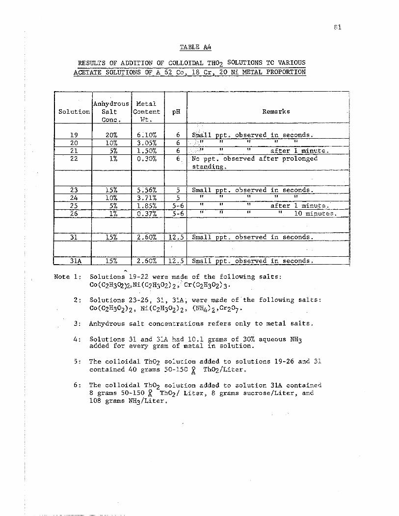
2. Two types of colloidal Tho2 solutions were added to the clear
solutions obtained in Step 1 above and the results are shotm in
Tables A3 and A4.
3. Colloidal Tho of different concentrations were added to a 35% 2
nitrate solution and the results are shown in Table A5, Prom this
work it was concluded that the optimum Tho2 concentrat2on was 5m the
3 order of 30-100gIdm . 4 . Manufacturing companies making colloidalizing agents were con-
tacted and the most promising agents were those of the nonionfe oetyk-
phenoxyethanol series made by Rohm and Haas. The products are of the
type commonly described as aklyParylpolyether alcohols, arndl have the
following structural formula:
Two members of this series were used in our experiments and these
were as follows:
Triton X-100 (X = 9-10) Triton X-200 (X = 19-21)
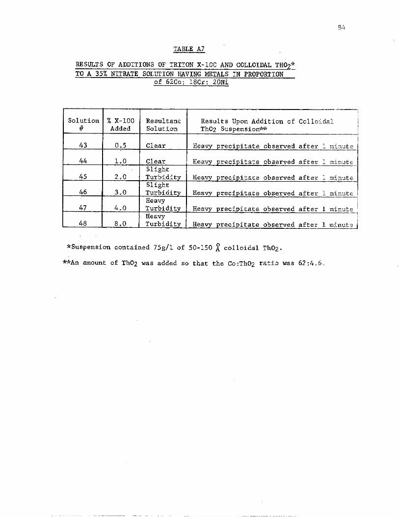
These agents were added t o a 35% metal n i t r a t e s a l t so lu t ion ,
the metals were i n proport ion of 62Co: 18Cr: 20Ni, The percentage
of these surface a c t i v e agents , t h e i r r e s u l t s upon the n i t r a t e
so lu t ions , and t h e r e s u l t s obtained upon add i t ion of the ctolloidal
Tho2 solu t ion , a r e shown i n Tables A6 and A 7 .
From the preceding work it was concluded t h a t a 35% n i t r a t e s a l t
3 so lu t ion with c o l l o i d a l Tho of 30-100g/dm concentrat ion added was
2
t h e bes t formulation,
Since i t was found t h a t a 35% n i t r a t e so lu t ion-col lo idal
t h o r i a suspension i s only s t a b l e f o r a few minutes, it was eoneluded
t h a t the mixing of t h e two solu t ions should be performed j u s t prfor
t o the en te r ing of t h e so lu t ions t o t h e ' F l a s h Dryer.
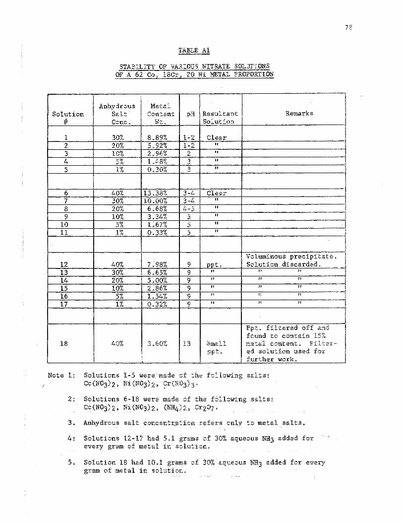
TABLE Al
STABILITY OF VARIOUS NITRATE SOLUTIONS O F A A62 Cs, I$Cr, 20 Ni NET& PROPORTXON
Note 1: Solutions 1-5 were made of the following salts: / ~ ~ ( N o ~ I 2, Ni &NO3) 2, Cr(NOg) g o
2: Solukions 6-18 were made of the following salts: Co(NO3129 Ni(N0312, (w4129 Cr207°
3 . Anhydrous salt eoncentration refers only to metal salts.
4 : Solutions 12-17 had 5,1 grams of 30% aqueous N?33 added for "
every gram of metal in sohution,
5. Solution 1% had 10.1 grams of 30% aqueous EX3 added for every gram of metal in sslutisn.
STABILITY OF VARIOUS ACETATE SOL,WIONS OF A 62 Co, 18 C r , 20 N i NETAIL PROPORTIOM
Note 1: So lu t ions 19-22 were made of t h e fol lowing s a l t s : Co(C2H30212 M i gC2830212, Cr(C2H30213
2: So lu t ions 23-31 were made of t h e fol lowing s a l t s : Co(C2H302) 2 N i c e ~ ~ ~ 0 2 ) 2, ( W 4 ) 2 , Cf207
3: Anhydrous s a l t concent ra t ion r e f e r s only t o metal s a l t s .
4 : So lu t ions 27-30 had 5 , l grams of 30% aqueous NB3 added f o r every gram of metal i n so lu t ion .
5: S o l ~ l t i o n 31 had 1 0 , l gram9 of 30% aqueous W g added f o r every gram of meta l i n s o l u t i o n ,
TABLE 83
RESULTS OF ADDP"HIQN OF CQLLQHDAL 'TliiJBy SOLmEOMS TO VARIOUS - NITRATE SOLWIONS OF A 62 60, $8 Cr, 20 N1 METAL PROPORTION
Note 1: Solutions 1-5 were made of t h e following s a l t s : co (No%) 2 9 N% (NO31 2 9 C r ( N 0 3 1 3 0
2: Solut ions 6-11, 18, %8A9 were wade of t h e folBowing s a l t s : Co(NQ3)2> NI(MO3)2, (NH4)%, Cr20g.
3: Anhydrous s a l t concentrat ion r e f e r s only Lo metal s a l t s ,
4 : Solutions 18 and 18h had P0,1 g r m s of 30% aqueous NH3 added f o r every gram of metal in so lu t ion ,
'*F 5: The e o l l o f q a l ThOa so lu t ion added to so lu t ions 1-11 and 18
contained 40 grams 50-150 ~ h O ~ / ~ P t e ; l - .
- 6: The c o l l o i d a l Tho2 solsecion added t o so lu t ion 98A contained
8 grams 50-150 2 T h O ~ B ~ i t e r , 8 grams s u c r o s e l l i t e r , and 108 grams M ~ / L i t e r ,
TABLE A4
RESULTS OF ADDICTION OF COLLOIDAL THO7 SOLUTIONS TO VARIOUS - ACETATE SOLUTIONS OF A 62 Co, 18 Cr, 20 Ni METAL PROPORTION
Remarks
Note 1: Solutions 19-22 were made of the following salts: CQ (C2H3%)2pNi(C~H302) 2 9 ' @x(C~H%Q~I 3
2: Solutions 23-26, 31, 318, were made of the following salts: Co(C2H3029 2 Ni C2H302) 2 9 (NH&a 2 2 C9207 .
3: Anhydrous salt concentrations refers only to metal salts,
4: Solutions 31 and 3BA had 18.1 grams of 30% aqueous ?!El3 added for every gram of metal in solution.
5: The colloidal Tho2 solution added to solutions 19-26 and 31 contained 40 grams 50-150 ThOzJLiter.
6 : The eolEoida1 Tho2 solution added to solution 318 contained 8 grams 50-150 Tho2/ Liter, 8 grams sucrose/Liter, and 108 grams NH3/kiter.
TABLE A5
RESULTS OF ADDITIONS 69P COLLOIWL THO? SUSPENSION OF &
DIPFEIEW 6ONCEmIShPT'H:ONS TO h 35% NETMTE S69LBBa"HON HAVING mThLS IN PROPORTION OF 6260:186r:28Ni
*Tho2 weight added to metal eontent.
RESULTS OF ADDITIONS OF "IIRBWN X-100 AND CBLLOIML THO?* - TO A 35% NITRATE SOLUTION WVIHG HETALS IN PROPORTION OF
62Co: 18Cr: 20Nf
*Suspens ion contained 7'5g/l 0% 50-150 collddal Th02.
**An mount sf Tho2 was added so that the Cs:Th02 ratio was 6 2 : 4 . 6 ,
TABLE AS
RESTJLTS OF ADDITIONS OF TRITON X-100 AND COLLOIDAL THO?* L.
TO A 35% NITRATE SOLUTION HAVING METALS I N PROPORTION of 6260: 18Cr: 20Ni
*Suspension contained %5g/P of 50-150 c o l l o i d a l ThO2.
**An amount of Tho2 w a s added so t h a t t h e Co:Th02 r a t i o was 62:4,6*
APPENDIX II
AREAL AND LINEAL ANALYSES PROCEDURES
(Ref. W. Rostoker and J. Dvorak, "Pntekpretation of Metallographic Structures," 1965, pp. 195-219, Academic Press, N,Y.)
PROCEDURE :
1. Procure photomicrograph of material at a magnification where the
average particle size is approxjimately 0.5 cm.
2. Construct a square or rectangular area so that approximately
100 particles are within that area,
3 . Measure the diameter of each of these 100 particles in microns,
4. Total the number of particles (91, 92 ....) at each diameter s i z e ,
that is, at .Ole, .02+ .03&, etc. (Dl, D2, Dg, etc.).
5. ~alc;late the total area (Ap) covered by particles
6. Calculate area fraction (F)
2 F = L!p- where At = Area (in3 ) encompassed by square or At rectangle as per Step #2.
NOTE: P also equals volume fraction ~A.B. Wenterbottm in 'The Physical Examination of Metals", (B. Chalimess and A. G, QuarrelS, editors), Chapter I., Arnold, London, 19602
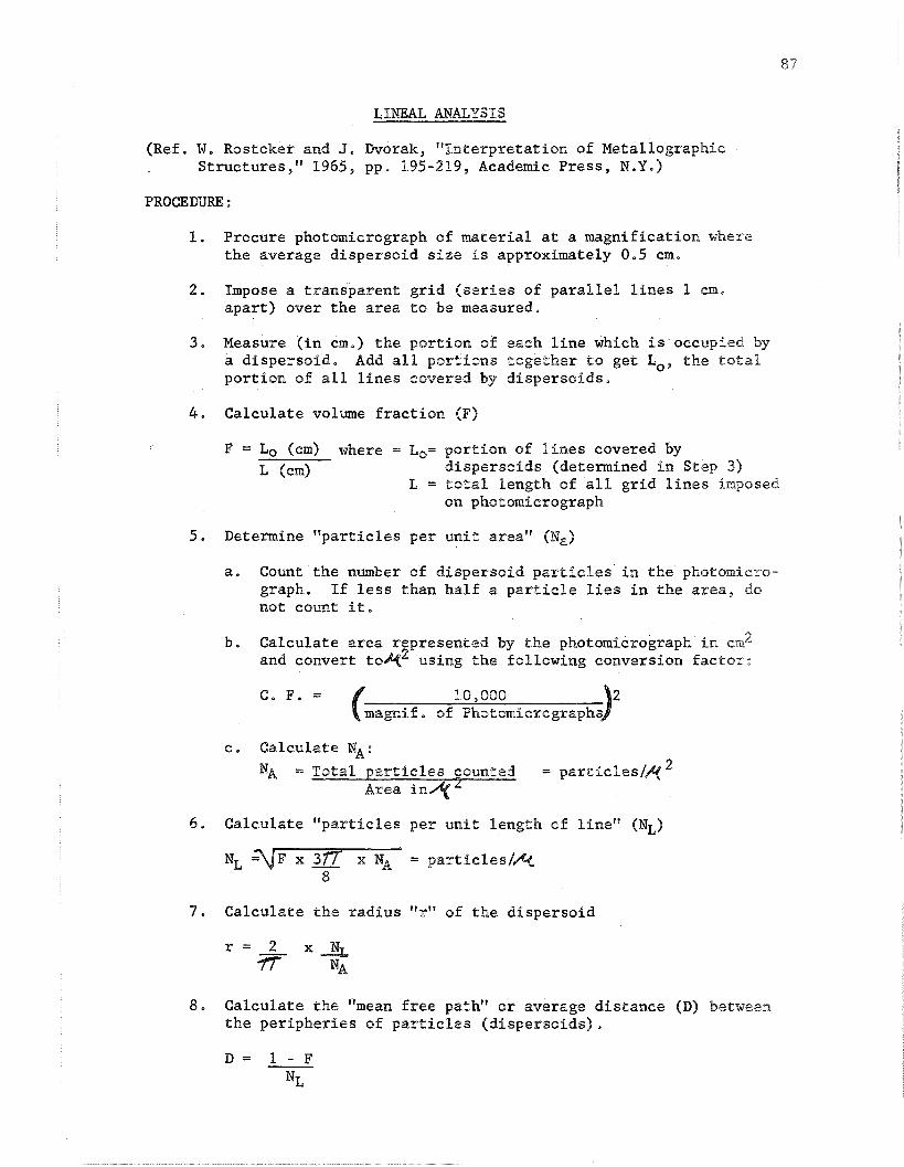
LINEAL ANALYSIS
(Ref. W. Rostoker and J, Dvorak, "Interpretation of Metallographic Structures," 1965, pp. $95-219, Academic Press, N.Y.)
1. Procure photomicrograph of material at a magnification where the average dispersoid size is approximately 0.5 cm.
2. Impose a transparent grid (series of parallel lines 1 cm, apart) over the area to be measured,
3. Measure (in cm.) the portion of each line which is occupied by a dispersoid. Add all portions together to get Lo, the total portion of all lines covered by dispersoids.
4. Calculate volume fraction (F)
F = Lo (ern) where = Lo= portion of lines covered by L (4 dispersoids (determined in Stlep 3)
L = total length of all grid lines imposed on photomicrograph
5. Determine "particles per unit area" (N,)
a, Count the number of dispersoid particles in the photorniero- graph. If less than half a particle lies in the area, do not count it,
b, Calculate area represented by the photomicrograph in cm2 and convert toe2 using the following conversion factor:
c, Calculate NA:
NA = Total particles counted = particles/& 2 Area i n 4
6, Calculate "particles per unit Length of line" (NL)
7 . Calculate the radius "r" of the dispersoid
8. Calculate the "mean free pathvP or average distance (D) between the peripheries of particles (dispersoids).
APPENDIX III
E m M a I O N REPLICA MICROSCOPY
EmUm EON REPLICA IMHCROSCOPP
The techniques used in making the extraction replicas and in deter-
mining the size of the particles were as follows:
The samples were initially mechanically polished by standard
metallographic techniques, The Tho2 particles were then put in relief
above the polished surfaces by electropolishing the samples in an ekec-
trolyte of 3 parts phosphoric acid and 2 parts sulfuric acid at appsoxi-
mately 30 volts, The polishing time was about 3 to 5 seconds, Approxi-
9 mately 250 A of carbon was then vapor deposited. onto the surfaces of the
samples, The carbon layers, with the Tho2 particles adhering to them,
were then freed from the surfaces of the samples by electropolishing
further in an electrolyte of 5% perchloric acid in acetic acid at
approximately 6 volts, The freed carbon replicas were then picked up
on microscopic grids, washed in distilled water, and examined bly
electron microscopy.
The size of the particles were measured directly frorrl the
micrographs by a manual method, Using a 4X magnifying glass the smallest 0
particle that could be measured was 0,%5mm, corresponding to 3% h on a
print of 68,750X.
The median particle diameter size is obtained from the 50%
point on a cumulative per cent-particle diameter graph.
The average particle diameter is calculated by multiplying the
number of particles of each size by the diameter, adding the products
together, and dividing by the total number of particles.
APPEmPX 73'
REPORT D P S T R I E ~ I O W LIST
FINAL REPORT DISTRIBUTION LIST FOR COESS"MCT NAS3-lkl6l
NASA Headquarters 600 Independence Avenue Washington, DOC, 20546 Attn: G o 6, DeutschfRIFM (1)
R. H. RaringfRRM (1) J. Gangler/~ (1) No RePcosfIPAP (1)
NASA Lewis Research Center 21008 Brookpark Road Cleveland, Ohio 44135 Attention: G, Ma Ault/MS 105-1 N. To Saunders/MS 185-1
(f 1 (1)
A, E, Anglin/~S 106-1 (11 F. H. Harf/MS 106-1 (5) C. P. BBankinship/MS 105-1 (1) M, Quatinetz/~S 49-1 (11 S . W. Weeton/MS 49-1 Dr, To HerbellIMS 49-1