40
| Date post: | 01-Jun-2018 |
| Category: |
Documents |
| Upload: | suwardi-cakra-ningrat |
| View: | 266 times |
| Download: | 4 times |

8/9/2019 Process Plant Piping Design
http://slidepdf.com/reader/full/process-plant-piping-design 1/40

8/9/2019 Process Plant Piping Design
http://slidepdf.com/reader/full/process-plant-piping-design 2/40
A piping system conveys fluid from onelocation to another. Within a process
plant, the locations are typically one or
more equipment items (e.g., pumps,
pressure vessels, heat exchangers,
process heaters, etc.), or individual process plants that are within the
boundary of a process facility .

8/9/2019 Process Plant Piping Design
http://slidepdf.com/reader/full/process-plant-piping-design 3/40
A piping system consists of: Pipe sections
Fittings (e.g., elbows, reducers, branch
connections, etc.) Flanges, gaskets, and bolting
Valves
Pipe supports and restraints
Each individual component plus the overall
system must be designed for the specified design
conditions.

8/9/2019 Process Plant Piping Design
http://slidepdf.com/reader/full/process-plant-piping-design 4/40
8/9/2019 Process Plant Piping Design
http://slidepdf.com/reader/full/process-plant-piping-design 5/40
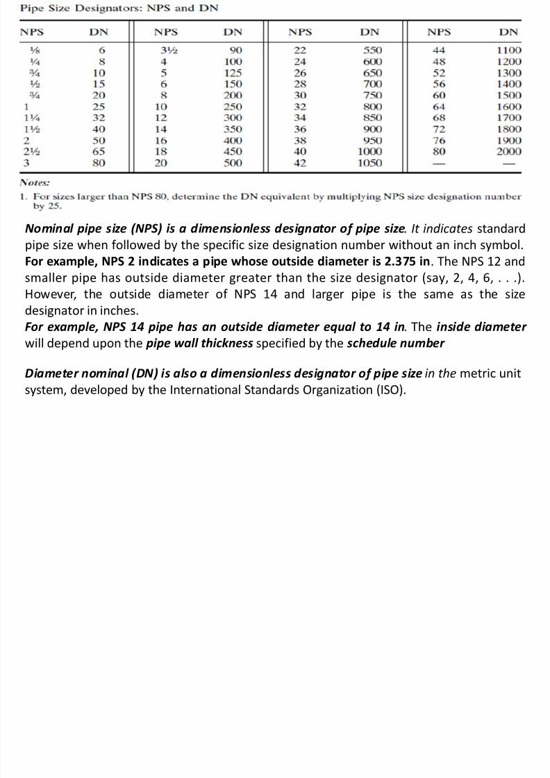
Nominal pipe size (NPS) is a dimensionless designator of pipe size. It indicates standard
pipe size when followed by the specific size designation number without an inch symbol.
For example, NPS 2 indicates a pipe whose outside diameter is 2.375 in. The NPS 12 and
smaller pipe has outside diameter greater than the size designator (say, 2, 4, 6, . . .).
However, the outside diameter of NPS 14 and larger pipe is the same as the size
designator in inches.
For example, NPS 14 pipe has an outside diameter equal to 14 in. The inside diameter
will depend upon the pipe wall thickness specified by the schedule number
Diameter nominal (DN) is also a dimensionless designator of pipe size in the metric unit
system, developed by the International Standards Organization (ISO).

8/9/2019 Process Plant Piping Design
http://slidepdf.com/reader/full/process-plant-piping-design 6/40
PIPE SCHEDULE :
S
PSN
1000=
SN = Schedule Number
P = Service Pressure (psi)
S = Allowable Fiber Stress (psi)
Std (Standard) ; S (STRONG ; XS (extra strong)

8/9/2019 Process Plant Piping Design
http://slidepdf.com/reader/full/process-plant-piping-design 7/40
A106 Grade B Carbon Steel Pipes - Pressure and Temperature Ratings
Pressure (psig) and temperature (deg F) ratings of A106 Grade B carbon steel pipes -
temperatures ranging 100 oF - 750 oF

8/9/2019 Process Plant Piping Design
http://slidepdf.com/reader/full/process-plant-piping-design 8/40
The accepted formula is Schedule Number = 1,000 x (P/S)
where,P = internal pressure, pounds-per-square-inch-gauge (psig),
S = allowable fiber stress (ultimate tensile strength of the steel in
psi).
Rearrange terms to solve for P, assuming schedule number and Sare known. Therefore P = Schedule number x S/1,000
Calculate internal pressure (P) based on Schedule 40 steel pipe,
and an allowable fiber stress (S) value of 60,000-psi (ultimate
tensile strength for A106 Grade B Carbon Steel Pipe).
Therefore, P = 40 x 60,000/1,000 = 2,400-psi .
This is reasonable, based on a current-day published value of
2,847-psi for 1-inch Schedule 40 steel pipe (with the range
temperature 1000F – 7500F).

8/9/2019 Process Plant Piping Design
http://slidepdf.com/reader/full/process-plant-piping-design 9/40
B31.1 - Power Piping
B31.2 - Fuel Gas Piping
B31.3 - Process Piping
B31.4 - Pipeline Transportation Systems for Liquid Hydrocarbons and Other
Liquids
B31.5 - Refrigeration Piping and Heat Transfer Components
B31.8 - Gas Transmission and Distribution Piping Systems
B31.8S - Managing System Integrity of Gas Pipelines
B31.9 - Building Services Piping
B31.11 - Slurry Transportation Piping Systems
B31G - Manual for Determining Remaining Strength of Corroded Pipelines

8/9/2019 Process Plant Piping Design
http://slidepdf.com/reader/full/process-plant-piping-design 10/40
Terminologi yang digunakan pada material yang
digunakan pada pipa maupun sistem perpipaan.

8/9/2019 Process Plant Piping Design
http://slidepdf.com/reader/full/process-plant-piping-design 11/40
PIPING MATERIALS (GRADE)
UTS : Ultimate Tensile Strength YS : Yields Strength

8/9/2019 Process Plant Piping Design
http://slidepdf.com/reader/full/process-plant-piping-design 12/40
A106 Grade B Carbon Steel Pipes
(Pressure-Temperature Rating)
1) STD (standard)
= schedule 40
2) XS (extra strong)
= schedule 80

8/9/2019 Process Plant Piping Design
http://slidepdf.com/reader/full/process-plant-piping-design 13/40
PIPING STANDARDS (CLASS)

8/9/2019 Process Plant Piping Design
http://slidepdf.com/reader/full/process-plant-piping-design 14/40
Provides requirements for:
• Design• Materials
• Fabrication
• Erection• Inspection
• Testing

8/9/2019 Process Plant Piping Design
http://slidepdf.com/reader/full/process-plant-piping-design 15/40
Piping and piping components, all fluid services:
Raw, intermediate, and finished chemicals
Petroleum products
Gas, steam, air, and water
Fluidized solids
Refrigerants
Cryogenic fluids Interconnections within packaged equipment

8/9/2019 Process Plant Piping Design
http://slidepdf.com/reader/full/process-plant-piping-design 16/40
Piping systems for internal gauge pressures at or above zerobut less than 15 psi, provided that the fluid is nonflammable,
nontoxic, and not damaging to human tissue, and its design
temperature is from -20°F through 366°F.
Power boilers that are designed in accordance with the ASMEBoiler and Pressure Vessel Code Section I and external boiler
piping that must conform to ASME B31.1.
Tubes, tube headers, crossovers, and manifolds that are
located inside a fired heater enclosure.
Pressure vessels, heat exchangers, pumps, compressors, and
other fluid-handling or processing equipment. This includes
both internal piping and connections for external piping.
8/9/2019 Process Plant Piping Design
http://slidepdf.com/reader/full/process-plant-piping-design 17/40
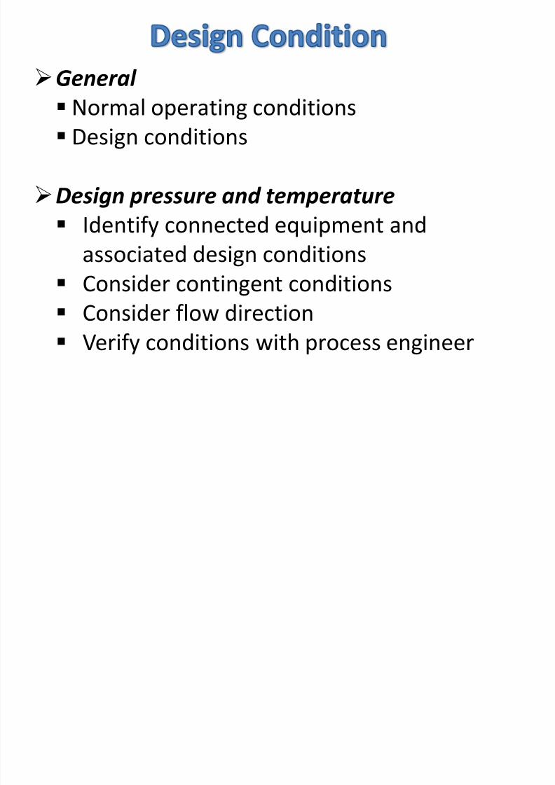
General
Normal operating conditions
Design conditions
Design pressure and temperature Identify connected equipment and
associated design conditions
Consider contingent conditions
Consider flow direction
Verify conditions with process engineer

8/9/2019 Process Plant Piping Design
http://slidepdf.com/reader/full/process-plant-piping-design 18/40
σl = Axial or Longitudinal Stress
σc = Circumferential (Hoop) Stress
σr = Radial Stress
t = Wall Thickness
P = Internal Pressure
8/9/2019 Process Plant Piping Design
http://slidepdf.com/reader/full/process-plant-piping-design 19/40
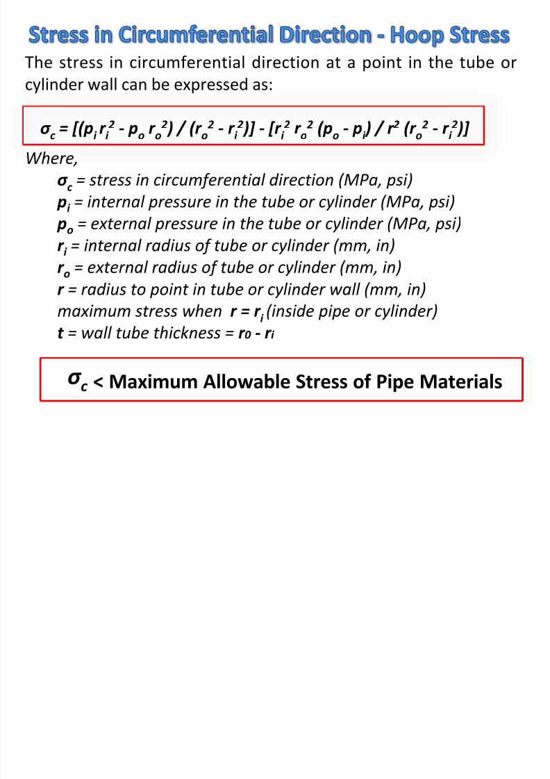
The stress in circumferential direction at a point in the tube or
cylinder wall can be expressed as:
σ c = [(pi r i 2 - po r o
2 ) / (r o2 - r i
2 )] - [r i 2 r o
2 (po - pi ) / r 2 (r o2 - r i
2 )]
Where,
σ c = stress in circumferential direction (MPa, psi)
pi = internal pressure in the tube or cylinder (MPa, psi)
po = external pressure in the tube or cylinder (MPa, psi)
r i = internal radius of tube or cylinder (mm, in)
r o = external radius of tube or cylinder (mm, in)
r = radius to point in tube or cylinder wall (mm, in)maximum stress when r = r i (inside pipe or cylinder)
t = wall tube thickness = r 0 - r i
σ c < Maximum Allowable Stress of Pipe Materials

8/9/2019 Process Plant Piping Design
http://slidepdf.com/reader/full/process-plant-piping-design 20/40
Function of : Material properties
Temperature
Safety factors
Established to avoid: General collapse or excessive distortion
from sustained loads
Localized fatigue failure from thermalexpansion load
Collapse or distortion from occasional loads

8/9/2019 Process Plant Piping Design
http://slidepdf.com/reader/full/process-plant-piping-design 21/40
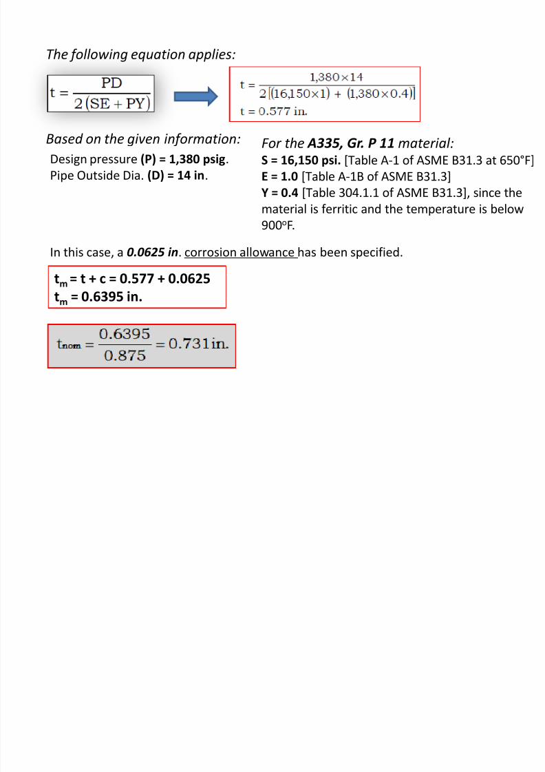
A piping system must be modified to add a new, spare
heat exchanger. You have been assigned the responsibility
to determine the required wall thickness for the pipe
from the heat exchanger to several pumps.
The piping system will have a design temperature of650°F .
The design pressure is 1,380 psig.
The pipe outside diameter is 14 in.
The material is ASTM A335, Gr. P11 (1¼ Cr – ½ Mo),Seamless Ferritic Alloy-Steel Pipe for High-Temperature
Service.
Corrosion allowance is 0.0625 in.
R i d W ll Thi k f I t l P f St i ht Pi
8/9/2019 Process Plant Piping Design
http://slidepdf.com/reader/full/process-plant-piping-design 22/40
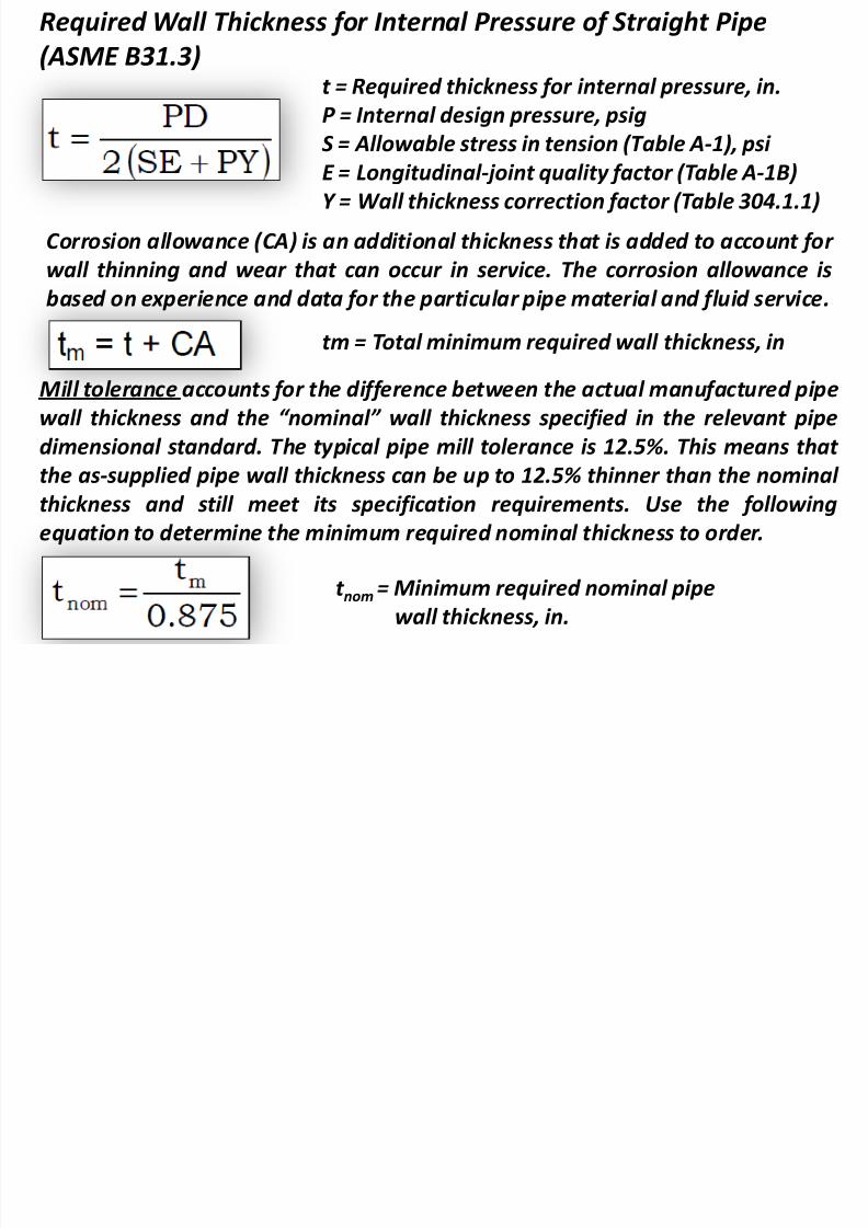
t = Required thickness for internal pressure, in.
P = Internal design pressure, psig
S = Allowable stress in tension (Table A-1), psi E = Longitudinal-joint quality factor (Table A-1B)
Y = Wall thickness correction factor (Table 304.1.1)
Required Wall Thickness for Internal Pressure of Straight Pipe
(ASME B31.3)
Corrosion allowance (CA) is an additional thickness that is added to account for
wall thinning and wear that can occur in service. The corrosion allowance is
based on experience and data for the particular pipe material and fluid service.tm = Total minimum required wall thickness, in
Mill tolerance accounts for the difference between the actual manufactured pipe
wall thickness and the “nominal” wall thickness specified in the relevant pipe
dimensional standard. The typical pipe mill tolerance is 12.5%. This means that the as-supplied pipe wall thickness can be up to 12.5% thinner than the nominal
thickness and still meet its specification requirements. Use the following
equation to determine the minimum required nominal thickness to order.
t nom = Minimum required nominal pipe
wall thickness, in.

8/9/2019 Process Plant Piping Design
http://slidepdf.com/reader/full/process-plant-piping-design 23/40
Source : ASME B31.3 (Table A-1) Basic Allowable Stress in Tension for Metal
Source : ASME B31.3 (Table A-1B) Basic Quality Factor for Longitudinal Weld Joint
8/9/2019 Process Plant Piping Design
http://slidepdf.com/reader/full/process-plant-piping-design 24/40

8/9/2019 Process Plant Piping Design
http://slidepdf.com/reader/full/process-plant-piping-design 25/40

8/9/2019 Process Plant Piping Design
http://slidepdf.com/reader/full/process-plant-piping-design 26/40
Pipe flanges that are made to standards called out
by ASME B16.5 or ASME B16.47 are typically madefrom forged materials and have machined surfaces.
ASME B16.5 refers to nominal pipe sizes (NPS) from
½" to 24“ and ASME B16.47 covers NPSs from 26"
to 60".
Each specification further delineates flanges into
pressure classes: 150, 300, 400, 600, 900, 1500 and
2500 for ASME B16.5; and ASME B16.47 delineatesits flanges into pressure classes 75, 150, 300, 400,
600, 900 . Flange strength increases with class
number.

8/9/2019 Process Plant Piping Design
http://slidepdf.com/reader/full/process-plant-piping-design 27/40

8/9/2019 Process Plant Piping Design
http://slidepdf.com/reader/full/process-plant-piping-design 28/40
8/9/2019 Process Plant Piping Design
http://slidepdf.com/reader/full/process-plant-piping-design 29/40
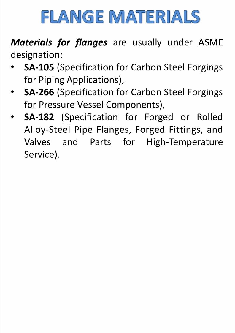
Materials for flanges are usually under ASMEdesignation:
• SA-105 (Specification for Carbon Steel Forgings
for Piping Applications),• SA-266 (Specification for Carbon Steel Forgings
for Pressure Vessel Components),
• SA-182 (Specification for Forged or Rolled
Alloy-Steel Pipe Flanges, Forged Fittings, and
Valves and Parts for High-Temperature
Service).
8/9/2019 Process Plant Piping Design
http://slidepdf.com/reader/full/process-plant-piping-design 30/40

8/9/2019 Process Plant Piping Design
http://slidepdf.com/reader/full/process-plant-piping-design 31/40
8/9/2019 Process Plant Piping Design
http://slidepdf.com/reader/full/process-plant-piping-design 32/40
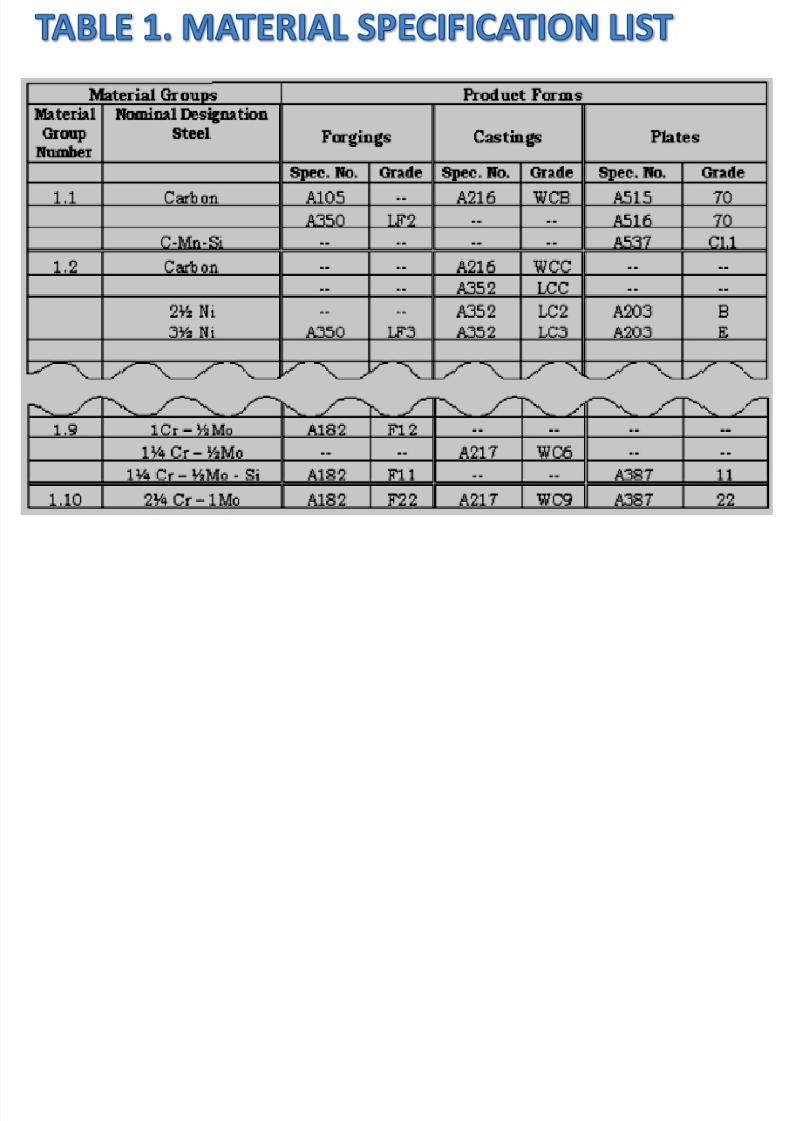
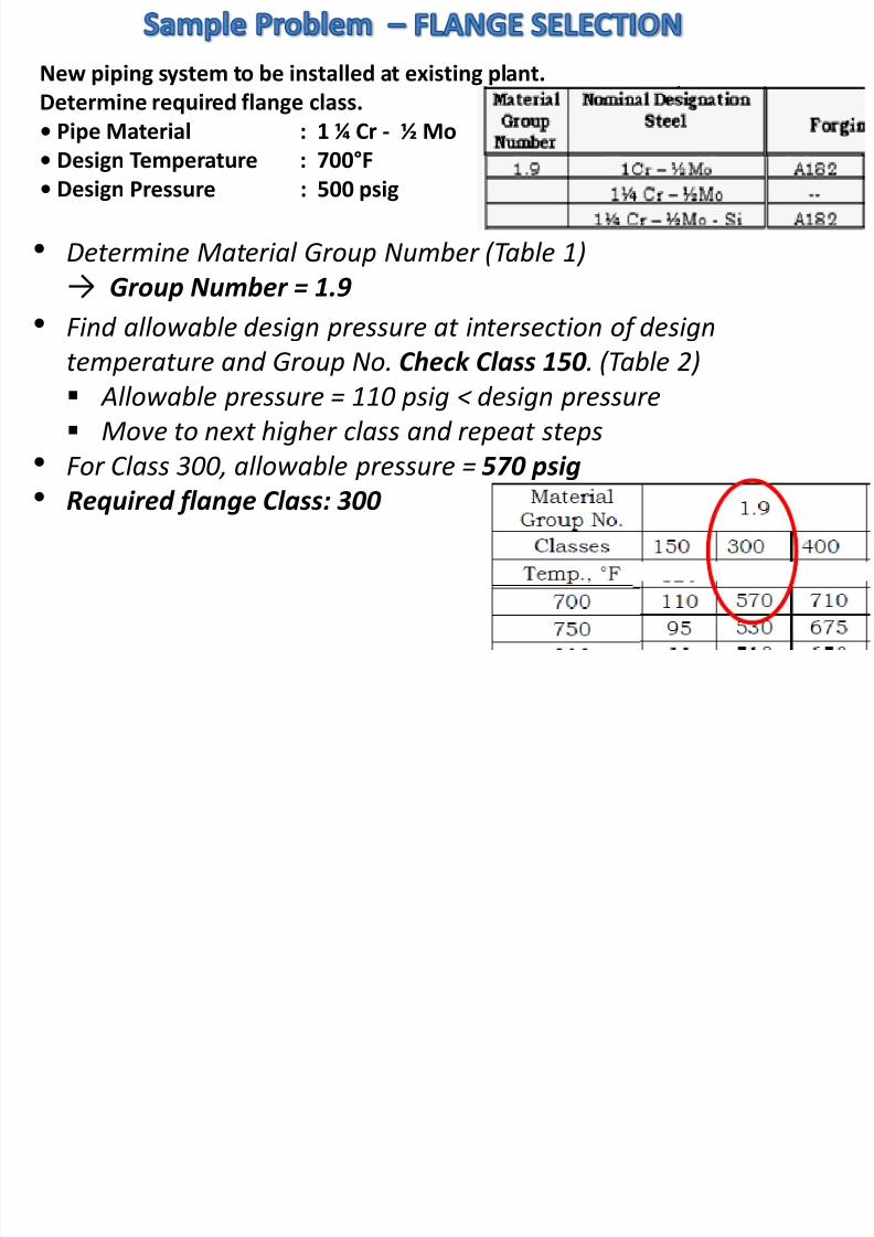
New piping system to be installed at existing plant.
Determine required flange class.
• Pipe Material : 1 ¼ Cr - ½ Mo
• Design Temperature : 700°F• Design Pressure : 500 psig
• Determine Material Group Number (Table 1)
→ Group Number = 1.9
• Find allowable design pressure at intersection of design
temperature and Group No. Check Class 150 . (Table 2)
Allowable pressure = 110 psig < design pressure
Move to next higher class and repeat steps
• For Class 300, allowable pressure = 570 psig• Required flange Class: 300

8/9/2019 Process Plant Piping Design
http://slidepdf.com/reader/full/process-plant-piping-design 33/40

8/9/2019 Process Plant Piping Design
http://slidepdf.com/reader/full/process-plant-piping-design 34/40

8/9/2019 Process Plant Piping Design
http://slidepdf.com/reader/full/process-plant-piping-design 35/40

8/9/2019 Process Plant Piping Design
http://slidepdf.com/reader/full/process-plant-piping-design 36/40
8/9/2019 Process Plant Piping Design
http://slidepdf.com/reader/full/process-plant-piping-design 37/40

8/9/2019 Process Plant Piping Design
http://slidepdf.com/reader/full/process-plant-piping-design 38/40

8/9/2019 Process Plant Piping Design
http://slidepdf.com/reader/full/process-plant-piping-design 39/40

8/9/2019 Process Plant Piping Design
http://slidepdf.com/reader/full/process-plant-piping-design 40/40


![14477462 Plant Layout Process Piping Roger Hunt[1]](https://static.documents.pub/doc/80x56/5492a7b6ac795952568b470b/14477462-plant-layout-process-piping-roger-hunt1.jpg)
