HAYWARD GORDON ULC Process Pumps & Mixers Operation and Maintenance Manual VERTICAL JACKETED SULPHUR PUMPS PROJECT: EQUIPMENT TAG: MODEL: QUANTITY: SERIAL NUMBER: LOCAL REPRESENTATIVE: CONTRACTOR: DATE: FOR INFORMATION, VISIT: www.haywardgordon.com FOR SERVICE AND INFORMATION, CONTACT: TORONTO Head Office & Plant MONTREAL CALGARY VANCOUVER (US West) Tel: (905)-693-8595 (514)-697-6445 (403)-253-2737 (604)-986-8764 Fax: (905)-693-1452 (514)-697-1164 (403)-253-1353 (604)-986-8794 Date of Issue: July 23, 2015
HAYWARD GORDON ULC endeavours to supply equipment of the highest quality both in materials and workmanship. However, within one year from date of startup or eighteen (18) months from date of shipment (whichever comes first) if any part of the equipment manufactured by HAYWARD GORDON ULC is proven to have been defective in material or workmanship, HAYWARD GORDON ULC shall have the right and obligation to promptly repair or replace such part F.O.B its works. Pumps or parts to be considered for warranty repair or replacement must be returned freight prepaid to Hayward Gordon’s factory at Halton Hills, ON. We reserve the right to require the return of defective parts before any claim is recognized. Materials are certified to be of the specified composition, however, the materials are not guaranteed against chemical attack or wear. No other warranty or condition, whether statutory or otherwise, is made, intended or to be implied and, except for its obligation to repair or replace defective parts as provided for above, HAYWARD GORDON ULC will not be responsible for any costs or damages, direct or indirect, which may result to the Purchaser from any defect in the equipment (whether of workmanship, material, design or otherwise) or from any breakage or stoppage thereof. Such costs specifically include, but are not limited to, equipment removal, re-installation, and freight. In any event, the liability of HAYWARD GORDON ULC arising through the supply of defective equipment shall not exceed the purchase price of the equipment. For equipment included in this unit but manufactured by others, HAYWARD GORDON ULC will endeavor to assign to the purchaser, the guarantee extended by such manufacturers to HAYWARD GORDON ULC. No modifications to this guarantee may be extended without the written authorization of a signing officer of HAYWARD GORDON ULC.
TABLE OF CONTENTS
I. INSTALLATION ................................................................................................................................... I-1 A. Unloading ........................................................................................................................................ I-1 B. Inspection ....................................................................................................................................... I-1 C. Storage ............................................................................................................................................ I-2 D. Cleaning .......................................................................................................................................... I-2 E. Location .......................................................................................................................................... I-2 F. Supporting Structure ..................................................................................................................... I-2 G. Mounting ......................................................................................................................................... I-2 H. Piping............................................................................................................................................... I-3 I. Heating Medium .............................................................................................................................. I-3 J. Important Warning ......................................................................................................................... I-3
II. OPERATION ....................................................................................................................................... II-1 A. Pre-Starting .................................................................................................................................... II-1 B. Initial Starting ................................................................................................................................ II-1 C. Necessary Checks ......................................................................................................................... II-1 D. Stopping Pump .............................................................................................................................. II-2
III. TROUBLESHOOTING ................................................................................................................... III-1 A. Vibration – Noise .......................................................................................................................... III-1 B. Overheating Bearings .................................................................................................................. III-2 C. Overheating Stuffing Box ............................................................................................................ III-2 D. No Discharge Flow ....................................................................................................................... III-2 E. Low Discharge Flow..................................................................................................................... III-3 F. Speed Too Low ............................................................................................................................. III-4 G. High Power Consumption ........................................................................................................... III-4
IV. MAINTENANCE ............................................................................................................................ IV-1 A. Field Testing and Inspection ...................................................................................................... IV-1 B. Grease Lubrication – Upper Bearings ....................................................................................... IV-1 C. Coupling Lubrication .................................................................................................................. IV-1 D. Stuffing Box with Packing .......................................................................................................... IV-1 E. Motor ............................................................................................................................................ IV-2
V. SERVICE & REPAIR ...................................................................................................................... V-1 A. Pump Removal ............................................................................................................................. V-1 B. Disassembly of Pump .................................................................................................................. V-1 C. Parts Inspection ........................................................................................................................... V-2 D. Axial (Top) Bearing Installation .................................................................................................. V-2 E. Sleeve Bearing Installation .......................................................................................................... V-2 F. Reassembly of Pump ................................................................................................................... V-3 G. Impeller Clearance Adjustment ................................................................................................... V-4 H. Spare Parts .................................................................................................................................... V-4 I. Parts Ordering .............................................................................................................................. V-5
VI. DRAWINGS ................................................................................................................................... VI-1
Hayward Gordon ULC Pumps·Mixers·Strainers Engineered Systems and Controls
CAUTION! Before putting pump into service carefully study and adhere to all sections of this manual, as this is necessary for safe and satisfactory operation of your new Hayward Gordon Pump.
A. Unloading
Care must be taken when unloading pump. Unit must be lifted from all four lifting points in each corner of the base.
WARNING!! An adequately sized crane or hoist must be used to lift unit. All lifting equipment (i.e. Chains, hooks and eyes) must be in accordance with local, or federal safety codes. Failure to use approved lifting equipment may result in serious injury.
B. Inspection
Inspection should be performed immediately after unloading pump. Examine equipment for broken, cracked, bent or missing parts. Carefully check:
1. Cover Plate
2. Motor, pedestal, coupling and flanges
3. Column, steam lines & discharge pipe
4. Pump casing
Report all damage or loss to the transportation company and Hayward Gordon.
Hayward Gordon ULC Pumps·Mixers·Strainers Engineered Systems and Controls
Inspect, recrate and store pump in dry location if not operated immediately. Protect from moisture, dirt, dust and pests.
1. Remove glands, packing and lantern ring from stuffing box. If mechanical seal, coat seal surfaces with light oil.
2. Cover pump suction, discharge and all openings with wood or cardboard.
3. Cover pump with tarpaulin if area has no protective covering.
4. Rotate shaft periodically to prevent pitting of bearing surfaces.
D. Cleaning
Clean surfaces of suction and discharge flanges before installation. If pump was in storage, re-grease upper bearing.
E. Location
Allow ample space for maintenance and inspection. Provide headroom and ventilation in a dry location.
Do not locate near dangerous or harmful elements or temperatures. Keep discharge piping direct with minimum of elbows (long radius preferred) and fittings.
F. Supporting Structure
Ensure the supporting structure is rigid enough to support the entire weight of the pump. The cover plate should be evenly supported and mounted level to within 0.5o of horizontal.
G. Mounting
Using Hayward Gordon ULC plans, check pump dimensions against foundation and piping dimensions to assure fit. The pump suction should not be located in the vicinity of any pipe that discharges fluids to the sump or in any other place where turbulence may cause air bubbles to enter the suction.
WARNING!! Attach the lifting devices to the cover plate – Do not lift the unit from the motor. Use the appropriate equipment to evenly distribute the load.
Hayward Gordon ULC Pumps·Mixers·Strainers Engineered Systems and Controls
Connecting of piping is done only after cover plate is finally anchored in place. Remove all foreign objects and debris from piping. The independent support for the discharge piping
should be near the pump to eliminate loads being transferred to the pump’s discharge pipe. Do not use the pump and cover plate to support the piping and contents. Never draw piping into place by use of force at the flanged discharge connection. Provide expansion joints, bends, loops and hangers to prevent nozzle loads. DISCHARGE PIPING Select the size of the discharge pipe so the frictional loss, plus static discharge head, plus working suction lift, does not exceed the total dynamic head on nameplate. Failure to consider the frictional losses will result in power wastage. Start the discharge pipe at the pump, ending at the final discharge point. Avoid abrupt pipe size changes and use only concentric taper increasers.
I. Heating Medium
Connect the steam supply to the fittings on the pump. If glycol is used instead of steam, make sure the heating lines have flange connections, not NPT connections. The steam supply pressure and temperature should be as specified by the Process Engineer. If not specified, steam supplied at 35 psig (2.47kg/cm), dry and saturated, is recommended as ideal for pure elemental sulphur pumping applications. In cases where the sulphur is known to contain viscosity-modifying materials (typically hydrogen compounds), the user may obtain satisfactory pumping conditions with higher steam pressures. The ideal temperature for glycol heating is 280F (138C).
J. Important Warning
The steam (or glycol) heating system should supply the sump heating coils well before the pump jacket. When steam is admitted to the pump jackets, the pump column expands towards the impeller (column grows more than the shaft). It is essential that the sulphur behind the impeller be molten to prevent the force of expansion from being transmitted to the rotating assembly causing impeller, shaft and bearing damage. Never apply power to the motor until the pump is fully supplied with sulphur. Extensive damage may result due to a dry running condition. During operation, a small amount of sulphur is constantly pumped upwards to the bearings to provide lubrication. Bypass passages then allow the sulphur to return to the sump.
Hayward Gordon ULC Pumps·Mixers·Strainers Engineered Systems and Controls
Before starting the pump, the entire mass of sulphur INSIDE and OUTSIDE the pump should be held at pumping temperature for several hours to permit all the parts to attain uniform operating temperature. Do not attempt to free the shaft of frozen sulphur during the heating period. Wait until the operating temperature has been attained and the shaft may be freely rotated by hand. Prepare motor as outlined by the driver manufacturer and conform to wire and fuse sizes, types and recommendations. All pumps rotate clockwise as viewed from motor looking down. Rotation arrow is located on the pump pedestal. Jog motor with the coupling disconnected to ensure wiring is properly connected.
STUFFING BOX Inspect stuffing box for proper packing. Ensure gland nuts are only finger tight.
WARNING Do NOT run pump dry as the rotating parts may seize without lubrication to the bearings.
B. Initial Starting
1. Wait for any temperature differences between pump and liquid to stabilize. Open discharge valve slightly to allow air to purge from the casing during starting.
2. Start motor. Open discharge valve slowly after pump has fully primed and operating at full speed. Otherwise, water hammer (shock) can seriously damage piping, fittings and joints.
3. Be sure pump is delivering liquid and running quietly.
4. Adjust the valve to the specified operating point.
C. Necessary Checks
Pump should operate satisfactorily if all instructions have been followed. Routine care of stuffing box and bearings is required; delay and expense may also be prevented by a study of the Troubleshooting section. Maintain the correct sulphur temperature during pumping. Failure to do so may result in an increase in viscosity known as “sulphur caramelization” which could overload the driver. (NOTE: often the shaft may be turned freely shortly after shutdown) Check the following and record any deviations which could indicate wear or possible problem.
1. Check the head and flow of the pump.
2. Check the amperage draw to the motor.
3. Check the temperature of the upper bearings.
Hayward Gordon ULC Pumps·Mixers·Strainers Engineered Systems and Controls
4. Indefinite Shutdown – remove seal/packing from box, flush and relubricate pump and motor bearings. Provide pump and motor with protective cover. Remove casing plug and drain casing and all piping.
Hayward Gordon ULC Pumps·Mixers·Strainers Engineered Systems and Controls
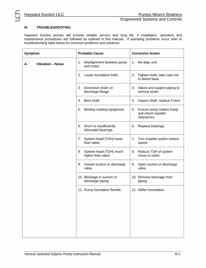
III. TROUBLESHOOTING Hayward Gordon pumps will provide reliable service and long life, if installation, operation and maintenance procedures are followed as outlined in this manual. If operating problems occur refer to troubleshooting table below for common problems and solutions.
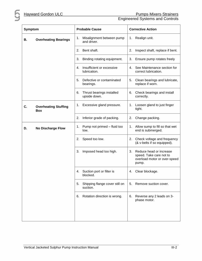
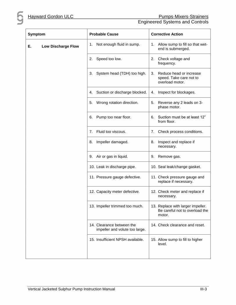
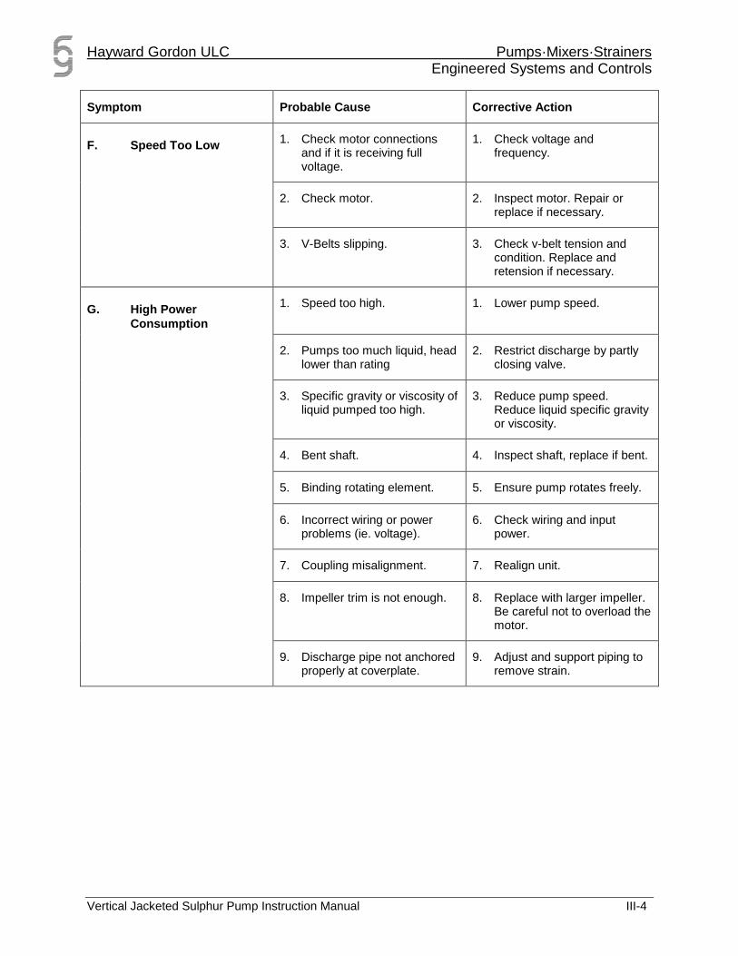
Symptom Probable Cause Corrective Action
A. Vibration – Noise 1. Misalignment between pump
and motor. 1. Re-align unit.
2. Loose foundation bolts 2. Tighten bolts, take care not
1. Check the differential head by measuring the suction and discharge pressures. Add the calculated discharge pipe losses to the differential head to achieve the Total Dynamic Head.
2. Check general operation of the pump with respect to noise and vibration.
3. Check speed and amperage draw of the motor.
4. If necessary, shut the discharge valve completely with the pump running and measure the shut-off pressure.
5. Check pump for unstable operation or excessive loading.
B. Grease Lubrication – Upper Bearings
The upper grease lubricated bearing is filled with grease at the factory and do not require filling before starting if units are put into service within 3 months of shipment. Use a Lithium base NLG1 Grade 2 grease to replenish the bearings with one ounce of grease every 2400 hours of continuous operation. Use a contact type thermometer mounted on the bearing housing to measure the bearing temperature. Do not "test" by hand as 120oF and higher may feel hot to the touch but bearing temperatures up to 180oF are normal, depending on ambient conditions. A sudden temperature increase indicates the possibility of damage that requires checking.
C. Coupling Lubrication
See individual manufacturer’s instructions for lubrication information.
D. Stuffing Box with Packing
Standard die-moulded packing is furnished in pump at time of shipment from factory. Use die-moulded rings only. (Never cut bulk packing for high speed shafts except in an emergency). REPACKING STUFFING BOX 1. Remove nuts, gland plate and split gland. 2. Remove all packing rings with packing hook. 3. Clean box and shaft. 4. Install packing; see Packing Procedure (below). PACKING PROCEDURE 1. Spin shaft by hand to see there is no binding. 2. Rub thin film of oil on shaft and in stuffing box. 3. Twist rings sideways to install packing. 4. Insert needed number of rings, staggering joints 90o and seating each ring individually. 5. Replace split gland, gland plate and nuts.
Hayward Gordon ULC Pumps·Mixers·Strainers Engineered Systems and Controls
SETTING NEW PACKING Break in new packing carefully. 1. Using wrench, tighten gland nuts snug, back off, and re-tighten finger tight. 2. Start pump (see Section II-A Initial Starting). 3. Check stuffing box for overheating.
E. Motor
See Manufacturer's Instructions.
Hayward Gordon ULC Pumps·Mixers·Strainers Engineered Systems and Controls
Refer to General Assembly drawings during dismantling. 1. Unhook wires, discharge lines and cover plate anchor bolts. 2. Attach flexible steam hoses to pump during removal from sump to ensure sulphur drains easily.
WARNING!! Never attach lifting devices to the motor. Lift the assembled unit from the cover plate.
3. Lift pump out of sump and lay horizontally on floor, resting on the casing and cover plate edge.
4. Use steam lancing, wire brush or sand blasting to remove any remaining sulphur. Do not use a welding torch or flame which can cause distortion.
5. Ensure all mating surfaces are free of sulphur, rust or other foreign material before reassembling. It is advisable to replace all gaskets when reconditioning or repairing the pump.
B. Disassembly of Pump
1. Refer to drawing 021-21465 for reference.
2. Remove motor.
3. Remove flexible coupling.
4. Unbolt discharge pipe (423) from pump casing (201).
5. Disconnect cross-over steam connections (708) at all points on column.
6. Unbolt casing (201) from column end plate.
7. Remove impeller bolt (D727) and pull impeller (202) off shaft.
8. Remove impeller back plate (425).
9. Remove bottom sleeve bearing (C418) from bottom column.
10. Remove bottom column bolts (F727) and bottom column (C431).
11. Remove intermediate bearing (A418) if present.
12. Continue in this manner and remove all columns and sleeve bearings.
13. Remove screws in top bearing housing (A730) and pull out shaft (401) and top Bearing housing assembly.
14. Grip shaft in vice lined with soft material to prevent scoring. Undo screws (B727) and remove bearing cap (410).
15. Push bearing housing (411) back to expose bearing, lock nut and lock washer.
16. Wipe off grease, straighten locking tab on lock washer (521), remove lock nut (520) and bearing (501) from shaft.
17. Remove bearing housing (411) from shaft.
18. Remove lip seals (A503, B503) from bearing housing and cap.
Hayward Gordon ULC Pumps·Mixers·Strainers Engineered Systems and Controls
1. Inspect ball bearing and sleeve bearings for damage and replace if necessary. If dirty, clean with kerosene or carbon tetrachloride, wipe dry, coat with oil and protect until ready to use.
2. Inspect impeller and replace if there is sufficient wear from corrosion or abrasion to affect performance.
3. Inspect and replace pump volute if there is sufficient scoring or other wear which could affect performance
4. Replace oils seals if worn or damaged. The lip seals are held by a press fit in the bearing cap and housing.
5. Replace packing if worn or damaged.
6. Replace lip seals if worn or damaged. Seals are held by a press fit in bearing cap and housing.
7. Check for bent shaft, shaft straightness to be 0.001” per foot of length.
8. Check shaft surface where lip seals seat for grooves or scoring. Check shaft surface where bearings seats for scoring. Replace shaft if necessary.
All parts must be clean before reassembly. This is especially important at retaining ring grooves, threads, gasket surfaces and bearing lubrication areas. Remove burrs with fine emery cloth especially on shaft surface.
D. Axial (Top) Bearing Installation
1. When installing three single angular contact bearings (2.5” shafts), ensure the bottom two bearings are mounted in tandem for a load in the downward direction. The third (top) bearing is to be mounted to take a load in the upward direction. A double row angular contact bearing (2” shafts) can be installed in either orientation.
2. Each individual bearing should be packed with grease to capacity with the bearing housing filled to approximately 1/3 of its total capacity.
E. Sleeve Bearing Installation
1. A cap screw (G727) is installed in each bearing to prevent its rotation within the housing. The cap screw should not make contact with the shaft as this would cause scoring.
2. The orientation of the bearing in the housing is important as this cap screw must come in contact with a pin or lubrication tube to prevent rotation.
3. Once a new sleeve bearing has been installed it should not be interchanged within the pump.
Hayward Gordon ULC Pumps·Mixers·Strainers Engineered Systems and Controls
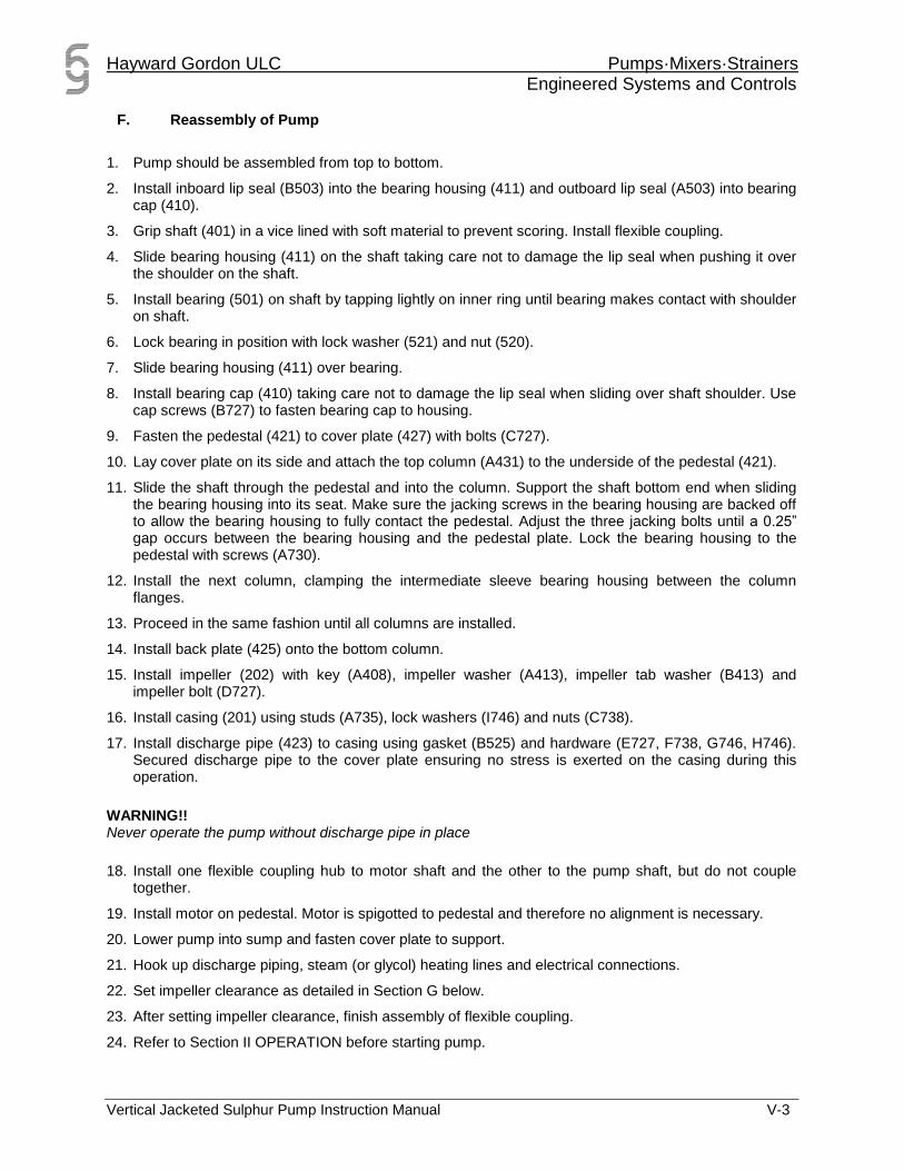
2. Install inboard lip seal (B503) into the bearing housing (411) and outboard lip seal (A503) into bearing cap (410).
3. Grip shaft (401) in a vice lined with soft material to prevent scoring. Install flexible coupling.
4. Slide bearing housing (411) on the shaft taking care not to damage the lip seal when pushing it over the shoulder on the shaft.
5. Install bearing (501) on shaft by tapping lightly on inner ring until bearing makes contact with shoulder on shaft.
6. Lock bearing in position with lock washer (521) and nut (520).
7. Slide bearing housing (411) over bearing.
8. Install bearing cap (410) taking care not to damage the lip seal when sliding over shaft shoulder. Use cap screws (B727) to fasten bearing cap to housing.
9. Fasten the pedestal (421) to cover plate (427) with bolts (C727).
10. Lay cover plate on its side and attach the top column (A431) to the underside of the pedestal (421).
11. Slide the shaft through the pedestal and into the column. Support the shaft bottom end when sliding the bearing housing into its seat. Make sure the jacking screws in the bearing housing are backed off to allow the bearing housing to fully contact the pedestal. Adjust the three jacking bolts until a 0.25” gap occurs between the bearing housing and the pedestal plate. Lock the bearing housing to the pedestal with screws (A730).
12. Install the next column, clamping the intermediate sleeve bearing housing between the column flanges.
13. Proceed in the same fashion until all columns are installed.
14. Install back plate (425) onto the bottom column.
15. Install impeller (202) with key (A408), impeller washer (A413), impeller tab washer (B413) and impeller bolt (D727).
16. Install casing (201) using studs (A735), lock washers (I746) and nuts (C738).
17. Install discharge pipe (423) to casing using gasket (B525) and hardware (E727, F738, G746, H746). Secured discharge pipe to the cover plate ensuring no stress is exerted on the casing during this operation.
WARNING!! Never operate the pump without discharge pipe in place
18. Install one flexible coupling hub to motor shaft and the other to the pump shaft, but do not couple together.
19. Install motor on pedestal. Motor is spigotted to pedestal and therefore no alignment is necessary.
20. Lower pump into sump and fasten cover plate to support.
21. Hook up discharge piping, steam (or glycol) heating lines and electrical connections.
22. Set impeller clearance as detailed in Section G below.
23. After setting impeller clearance, finish assembly of flexible coupling.
24. Refer to Section II OPERATION before starting pump.
Hayward Gordon ULC Pumps·Mixers·Strainers Engineered Systems and Controls
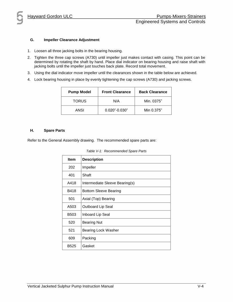
1. Loosen all three jacking bolts in the bearing housing.
2. Tighten the three cap screws (A730) until impeller just makes contact with casing. This point can be determined by rotating the shaft by hand. Place dial indicator on bearing housing and raise shaft with jacking bolts until the impeller just touches back plate. Record total movement.
3. Using the dial indicator move impeller until the clearances shown in the table below are achieved.
4. Lock bearing housing in place by evenly tightening the cap screws (A730) and jacking screws.
Pump Model Front Clearance Back Clearance
TORUS N/A Min. 0375”
ANSI 0.020”-0.030” Min 0.375”
H. Spare Parts
Refer to the General Assembly drawing. The recommended spare parts are:
Table V-1: Recommended Spare Parts
Item Description
202 Impeller
401 Shaft
A418 Intermediate Sleeve Bearing(s)
B418 Bottom Sleeve Bearing
501 Axial (Top) Bearing
A503 Outboard Lip Seal
B503 Inboard Lip Seal
520 Bearing Nut
521 Bearing Lock Washer
609 Packing
B525 Gasket
Hayward Gordon ULC Pumps·Mixers·Strainers Engineered Systems and Controls
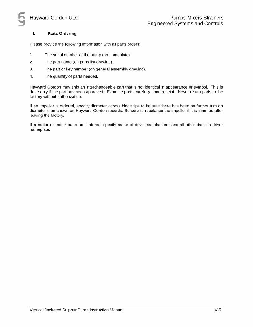
Please provide the following information with all parts orders:
1. The serial number of the pump (on nameplate).
2. The part name (on parts list drawing).
3. The part or key number (on general assembly drawing).
4. The quantity of parts needed.
Hayward Gordon may ship an interchangeable part that is not identical in appearance or symbol. This is done only if the part has been approved. Examine parts carefully upon receipt. Never return parts to the factory without authorization. If an impeller is ordered, specify diameter across blade tips to be sure there has been no further trim on diameter than shown on Hayward Gordon records. Be sure to rebalance the impeller if it is trimmed after leaving the factory. If a motor or motor parts are ordered, specify name of drive manufacturer and all other data on driver nameplate.
Hayward Gordon ULC Pumps·Mixers·Strainers Engineered Systems and Controls