26
Water Supply For the Alaska LNG Liquefaction Facility and Marine Terminal April 30, 2018 Leslie “Fritz” Krusen AKLNG-4030-PPP-PRS-DOC-00001
Water Supply For the Alaska LNG Liquefaction Facility and Marine Terminal April 30, 2018
Leslie “Fritz” Krusen
AKLNG-4030-PPP-PRS-DOC-00001

Agenda
• Alaska LNG Project Status
• Water Supply Flow Rates
• Industry Wells near the Alaska LNG Plant Site
• Hydrogeologic Studies at the LNG Plant Site
• Evolution from Onsite to City of Kenai Water Supply
• Existing/Anticipated City of Kenai Water Supply Parameters
• Next Steps
• Resources
2
Project Status
• Alaska LNG Commercial activities are gaining momentum– JDA Group (AGDC, Sinopec, Bank of China, China Investment Corp)
developing transition from “Framework” phase to “Definitive”
– Other announced MOU’s & LOI’s include KOGAS, Tokyo Gas, & PetroVietnam Gas; these are being advanced
– There are a number of un-announced MOU’s & LOI’s, that are also being advanced
– Negotiations continue with upstream producers re gas supply
– Discussions continue with DNR, DOR, and other SOA agencies re their roles
– Goldman Sachs & Bank of China appointed as investment advisors
– Discussions continue with Legislature to obtain Receipt Authority
3

Project Status
• Alaska LNG regulatory activities are on-schedule– FERC issued NEPA “schedule notice” in March
• Draft EIS by Mar, 2019; EIS by Dec, 2019; ROD by Mar, 2020
– Other major permit acquisitions are also advancing• Corps of Engineers Section 404, ADEC Air Quality, etc
– AGDC responded to 81% of the FERC 15 Feb, 2018 “DR4” comments• AGDC responded to 100% of the 2017 Data Requests (DR) 1, 2, & 3 comments
• ALNG LNG technical activities are positioning for action– JDA party roles under discussion
– Design/construction phase contracting strategy being finalized
– Commencement subject to gaining Receipt Authority & funding
4

Water Supply Flow Rates
• There are three water supply rates to remember:– 250 gpm peak during construction, overall period from about
2020-2026, to support personnel in the construction camp
– 150 gpm sustained for the full three-train operation, transitioning from construction say in 2028 (operations to start in 2024-2025) and continuing for 30 years or more• About 90% for combined-cycle power plant
– 1000 gpm for 24 hours to refill firewater tank as per NFPA code; may never occur but system must be capable
• Nearby operational facilities use more than 150 gpm since they have cooling towers as part of their process; Alaska LNG does not (we will use airfin coolers)
5

Industry Wells Near the LNG Plant Site
• LNG Facilities Onshore Hydrogeologic Report Table 2.2.1
6
Hydrogeologic Studies at the LNG Plant Site
• Under the direction of Alaska LNG Pre-FEED Joint Venture, Fugro Consultants Inc performed extensive hydrogeologic (and other) investigations at/near the LNG Plant Site from 2014-206
• About 130 boreholes were drilled at/near the Site, including– 26 groundwater Monitor Wells (“MW”)– Four Observation Wells (“OW”)– Three Aquifer Pump Test wells (“APT”)
• Although AGDC continues to negotiate with the Alaska LNG LLC (ExxonMobil, BP, ConocoPhillips) to gain control of the properties purchased thus far for the Site, AGDC owns the boreholes and wells
• Refer to the next three slides for location information
7
LNG Site Overview
8
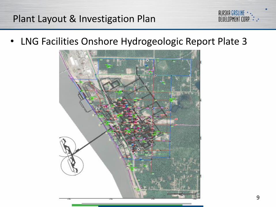
Plant Layout & Investigation Plan
• LNG Facilities Onshore Hydrogeologic Report Plate 3
9
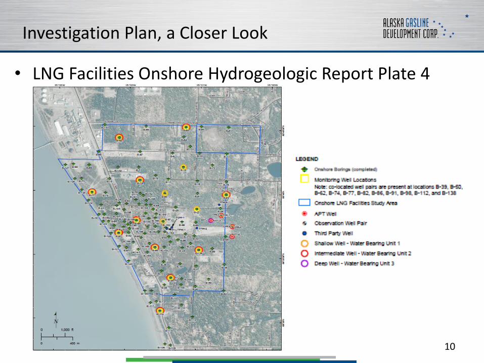
Investigation Plan, a Closer Look
• LNG Facilities Onshore Hydrogeologic Report Plate 4
10

Hydrogeologic Studies at the LNG Plant Site
• There are three aquifers in the vicinity of the Site:
– “Water Bearing Unit 1”, aka “Killey Unit”, aka “groundwater”. This is the aquifer that most residences and light industries draw from.
– “Water Bearing Unit 2”, aka “Upper Moosehorn”. This is the aquifer that most heavy industries near Nikiski draw from.
– Water Bearing Unit 3”, aka “Lower Moosehorn”. A few industrial wells are completed in this aquifer; but it is generally regarded as a fallback source, to be drawn from in Water Bearing Unit 2 is insufficient at a given location.
• The aquifers are separated by “aquitards” that exhibit some “leakance”
• Refer to the next three slides for transect & aquifer depth information
11
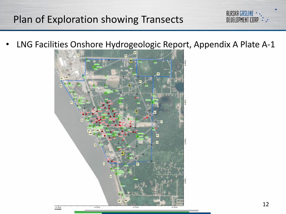
Plan of Exploration showing Transects
• LNG Facilities Onshore Hydrogeologic Report, Appendix A Plate A-1
12

Plan of Exploration, Transect H-H
• LNG Facilities Onshore Hydrogeologic Report, Appendix A Plate A-11
13
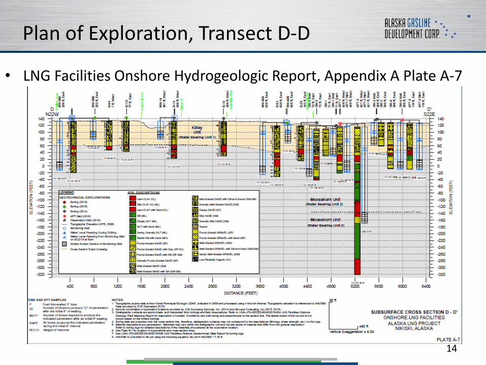
Plan of Exploration, Transect D-D
• LNG Facilities Onshore Hydrogeologic Report, Appendix A Plate A-7
14

Water Bearing Unit 1 (Groundwater) Summary
• “Unconfined”, and recharged by precipitation & nearby surface water bodies
• Discharges at the bluff, not in communication with Cook Inlet tides
• 14 Monitor Wells (“B”) plus part of two Observation Wells (OW-1 & OW-3) completed in this zone
• General flow towards west/southwest
• Not influenced by brief cleanup flows (100-300 GPM for 30 minutes) from the Aquifer Pump Test wells
• Although arsenic and petroleum hydrocarbons were detected in some of the wells; there were no instances of concentrations above ADEC Water Quality Standards
• OW-1 and OW-3 did have instances of certain metals (aluminum, chromium, etc) above ADEC Water Quality Standards
15
Water Bearing Unit 2 (Industry Source) Summary
• Confined by leaky aquitard from Unit 1, and recharged primarily from “upland distal” sources
• In communication with Cook Inlet tides, not known if this is due to hydraulic connection or changing overburden pressure
• 11 Monitor Wells (“A”) plus part of two Observation Wells (OW-2 & OW-4) completed in this zone
• General flow towards west/southwest• Quick recovery from brief cleanup flows (100-300 GPM for 30 minutes) from the
Aquifer Pump Test wells; indicates a “strong” aquifer• Arsenic detected above the ADEC 10 ppb limit in four MW’s (-39A, -50A, -62A, -
74A), OW-2 & OW-4, and APT-1 & APT-2. Maximum concentration was 131 ppb.• Trichloroethene (a solvent) detected above the ADEC limit of 0.005 mg/l (5 ppb)
in OW-4 and APT-1. Maximum concentration was 0.057 mg/l. Trichloroethenewas noted but below limit in OW-2.
• OW-2, OW-4, APT-1, & APT-3 did have instances of certain metals (aluminum, antimony, etc) above ADEC Water Quality Standards
• Trichloroethene presence reported to ADEC & FERC
16
Water Bearing Unit 3 (Deep Source) Summary
• Confined by slightly leaky aquitard from Unit 2, and recharged primarily from “upland distal” sources
• In communication with Cook Inlet tides, not known if this is due to hydraulic connection or changing overburden pressure
• For Alaska LNG, only penetrated by APT-3• Flow direction unknown, but presumably west/southwest• Poor recovery from brief cleanup flows (25 GPM for 30
minutes) suggests the aquifer is limited at this location• Arsenic detected but below the ADEC 10 ppb limit• Trichlorethene (a solvent) detected at 0.015 mg/l, above the
ADEC limit of 0.005 mg/l (5 ppb)• APT-3 did have instances of certain metals (aluminum,
antimony, etc) above ADEC Water Quality Standards
17

What is Trichloroethene?
• A hydrocarbon-based solvent
• Used in early 20th century as anesthetic (like chloroform), but ceased due to side effects
• Used for a while as a dry-cleaning solvent
• Primary use is as a de-greaser of metal parts
• I couldn’t locate the AEGL’s for Trichloroethene, but for Trichloroethylene & 1-hour: AEGL-2 = 450 ppm and AEGL-3 = 3800 ppm (AEGL = Acute Exposure Guideline Levels)
• Recall from the 12 Apr LNG Process Safety Meeting
– Benzene, 1-hr: AEGL-2 = 800, AEGL-3 = 4,000 ppm
– Propane, 1-hr: AEGL-2 = 17,000, AEGLE-3 = 33,000 ppm
– Note that AEGL’s are for “airborne”, and today’s context is “in water”18
Evolution from Onsite to City of Kenai Water Supply
• The problems with onsite water supply from APT-1/2/3 location, even though onsite water wells are the norm for Nikiski industry:– Arsenic in excess of 10 ppb, Trichloroethene in excess of 5 ppb
• Cannot dispose of aquifer pump test water back into ground, need ADEC permit for disposal in the Cook Inlet plus a logistical solution to get water to Cook Inlet
• Need to remove arsenic for construction camp application, additional cost
– Water Bearing Unit 3 not “strong”
– FERC needs a plan that they can review• Where to drill new APT wells?
• Plan must not “mobilize” the trichlorethene
• When to get permits, drill, and test?
• What if there is another “miss”?
– AGDC needs immediate funds to pursue onsite water supply
19
Evolution from Onsite to City of Kenai Water Supply
• Versus extending City of Kenai water supply line 6 miles plus making small modifications to the Kenai system– Pipeline along Kenai Spur Highway MP 14 to MP 20
– Drill two new wells in Beaver Loop Well Field
– Possible augmentation of filters
– Add two pump stations
• Feasibility demonstrated in a 2017 report by Nelson Engineering
• Cost about the same as onsite water supply, expenditure is deferred somewhat compared to onsite drilling/testing
• Disposal of aquifer pump test fluids anticipated to be not a problem, since no contaminants in excess of ADEC criteria
• Reduces fire insurance rates for industries and residences from MP 14-20 of Kenai Spur Highway
20

Existing/Anticipated Kenai Water Supply Parameters
• Demand:– Average daily demand, Aug 2016 to Jul 2017: 504 gpm
– Average summer demand, Aug 2016 to Jul 2017: 565 gpm
– Peak monthly average, 2014-2017: 625 gpm
– Estimated maximum daily average, 2014-2017: 847 gpm
– Estimated Kenai demand, 2025: 910 gpm
– Additional demand, new users MP 14-20: 232 gpm
– LNG plant construction camp demand: peak 250 gpm
– Design target 1400-1700 gpm, therefore need 1 or 2 new wells
• Existing filtration capacity: 1,042 gpm, augment filters?
• Existing storage: 3 million gallons @airport, 1 million @wellfield
• Pump stations:– One needed for the fire case to the LNG plant
– One needed to improve hydraulics elsewhere in Kenai
21

Next Steps
• Continue consultations with City of Kenai
• Recon within 2-mile radius of Beaver Loop wellfield, identify locations of private wells and likely locations for monitor wells
• Determine maximum pump test possible using existing system
• Develop next-level engineering scope that includes:– Updating existing hydrogeologic model
– Aquifer pump test plan; including duration, monitor points, disposal, & permitting
– Install monitor wells
– Obtain baseline well/water data for wells within impact radius
– Capacity test for filters; augment capacity if required
– Drill & complete 2 X 12” wells within Wellfield, add/replace 500 ft of yard piping, add yard pump station
– Add pump station at Seward Avenue
– Extend 16” HDPE line from MP14 to MP20
– Contingency plan for arsenic removal
– “For sanction” capex and opex estimates
– Issue-for-construction orders and packages for modified/new wells & facilities
• Continue low-level investigation of alternatives & reinforcements
22
Resources
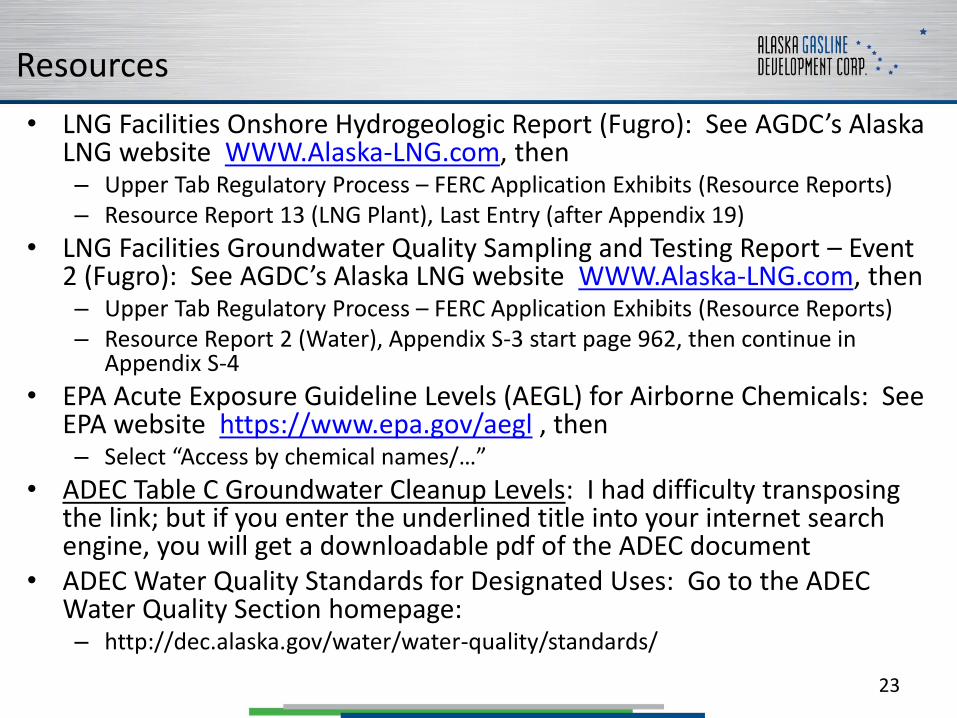
• LNG Facilities Onshore Hydrogeologic Report (Fugro): See AGDC’s Alaska LNG website WWW.Alaska-LNG.com, then– Upper Tab Regulatory Process – FERC Application Exhibits (Resource Reports)– Resource Report 13 (LNG Plant), Last Entry (after Appendix 19)
• LNG Facilities Groundwater Quality Sampling and Testing Report – Event 2 (Fugro): See AGDC’s Alaska LNG website WWW.Alaska-LNG.com, then– Upper Tab Regulatory Process – FERC Application Exhibits (Resource Reports)– Resource Report 2 (Water), Appendix S-3 start page 962, then continue in
Appendix S-4
• EPA Acute Exposure Guideline Levels (AEGL) for Airborne Chemicals: See EPA website https://www.epa.gov/aegl , then– Select “Access by chemical names/…”
• ADEC Table C Groundwater Cleanup Levels: I had difficulty transposing the link; but if you enter the underlined title into your internet search engine, you will get a downloadable pdf of the ADEC document
• ADEC Water Quality Standards for Designated Uses: Go to the ADEC Water Quality Section homepage: – http://dec.alaska.gov/water/water-quality/standards/
23
Presentation End
• Thank you!
• Questions?
• Backup slides follow…
24
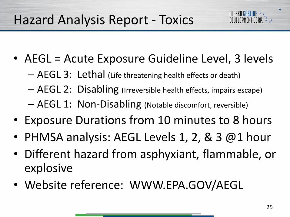
Hazard Analysis Report - Toxics
• AEGL = Acute Exposure Guideline Level, 3 levels– AEGL 3: Lethal (Life threatening health effects or death)
– AEGL 2: Disabling (Irreversible health effects, impairs escape)
– AEGL 1: Non-Disabling (Notable discomfort, reversible)
• Exposure Durations from 10 minutes to 8 hours
• PHMSA analysis: AEGL Levels 1, 2, & 3 @1 hour
• Different hazard from asphyxiant, flammable, or explosive
• Website reference: WWW.EPA.GOV/AEGL
25
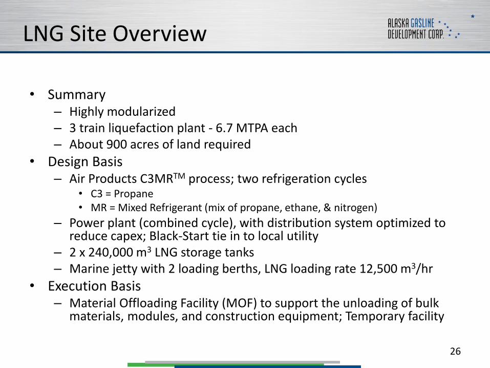
LNG Site Overview
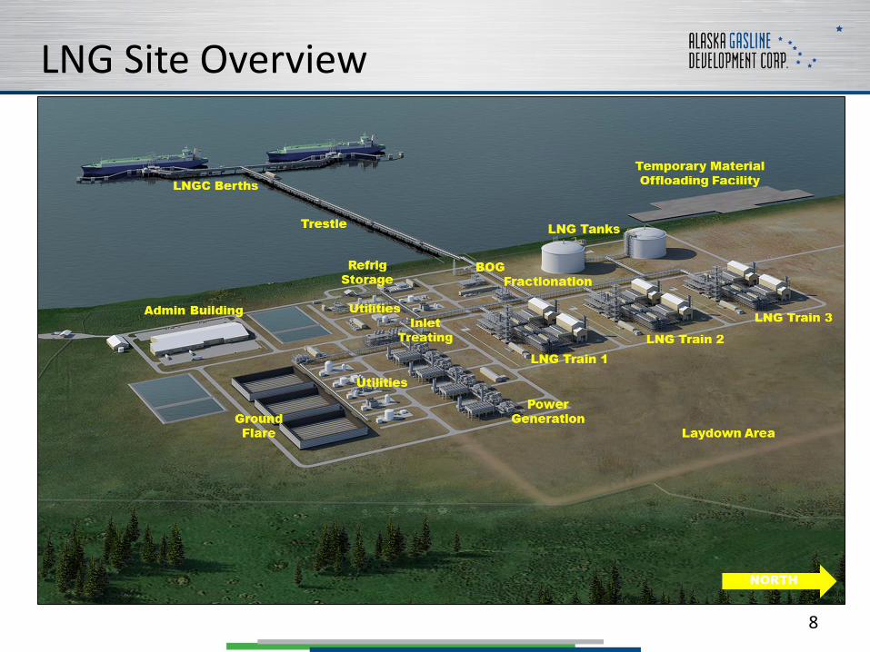
• Summary– Highly modularized – 3 train liquefaction plant - 6.7 MTPA each– About 900 acres of land required
• Design Basis– Air Products C3MRTM process; two refrigeration cycles
• C3 = Propane• MR = Mixed Refrigerant (mix of propane, ethane, & nitrogen)
– Power plant (combined cycle), with distribution system optimized to reduce capex; Black-Start tie in to local utility
– 2 x 240,000 m3 LNG storage tanks– Marine jetty with 2 loading berths, LNG loading rate 12,500 m3/hr
• Execution Basis– Material Offloading Facility (MOF) to support the unloading of bulk
materials, modules, and construction equipment; Temporary facility
26


