Process simulation controlled by demons:
An AI approach for predicting the
reliability of electrical substation
architectures prior to design
R. Sandner" & A. Montoya*
* Fraunhofer-Institute for Industrial Engineering,
D-7000 Stuttgart, Germany
* General Electric Protecciones y Control S.A.,
E-48080 Bilbao, Spain
SUMMARY
The paper describes a methodological approach for integrating mathematical
models of primary and secondary equipment of an electrical substation into a
qualitative behavioural representation by means of interacting objects. The
major innovative potential of this approach lies in the possibility to allow for
an easy estimation of system reliability and behaviour of equipment under
disturbances for even not yet existing substation architectures. This enables the
protection engineer to test several design alternatives off-line before the actual
implementation at a substation will take place. Therefore, the object-oriented
simulation tool called SUB SIM has been developed, running on a 486 PC un-
der MS-Windows.
Transactions on Information and Communications Technologies vol 1, © 1993 WIT Press, www.witpress.com, ISSN 1743-3517
96 Artificial Intelligence in Engineering
INTRODUCTION
Electrical substations are the linking support of the three phases of the electri-
cal energy cycle, which consists of generation, transmission, and distribution
of energy. Through all primary and secondary equipment located in a sub-
station, the entire power network is monitored, controlled, and protected. As a
result of this, any fault in the power network is reflected in the secondary com-
ponents of the electrical substation, causing a protection relay to transmit a
tripping order to its related high-voltage or medium-voltage equipment or
forcing the equipment to send an alarm to the control centre. Vice versa, every
problem or failure in the substation minimises the performance of the whole
network. Thus, the reliability rate of the electrical energy cycle depends, in a
large proportion, on the reliability of primary and secondary components of the
substation [1].
Most of all, the availability of the protection and control system is responsible
for the stability of the electrical power network. The reliability of protection
and control strongly depends on the degree of centralisation or decentralisation
of the different functions, i.e. on the degree of integration and the distribution
between the different levels of a substation architecture, namely between level
1 (the bay level) and level 2 (the substation level) [2].
Digital relays provide a high degree of flexibility providing all of the protec-
tion functions as well as fault location and data communications capability. [3].
A very new approach are attempts to integrate control functions like measure-
ment acquisition, sequential commands of HV/MV equipment, interlocking or
synchronising into the same set of digital relays in order to reach a highly in-
tegrated link between protection and control. However, there are nearly no ex-
periences concerning the availability and reliability of these new different ar-
chitectures of system integration.
Transactions on Information and Communications Technologies vol 1, © 1993 WIT Press, www.witpress.com, ISSN 1743-3517
Artificial Intelligence in Engineering 97
This paper, which is based on previous research work undertaken in a Euro-
pean joint research project of the BRTTE/EURAM programme, describes how
the reliability of new protection and control system architectures can be as-
sessed by using qualitative models of electrical substations, which represent the
mathematical characteristics of the different components by means of inter-
acting objects.
THE STRUCTURE OF SUBSTATION MODELS
Computer simulation is the problem-solving process of predicting the future
state of a real system by studying an idealised computer model of the real
system, especially whenever it would be too costly or impracticable to obtain
the predictive information with real devices [4].
Usually, the model cannot represent the real system completely, but always
represents an idealised approximation. Thus, the quality of the model-based
simulation always depends on how good the quantitative or qualitative ap-
proximation represents the most important features of the real system. Espe-
cially in the simulation of the operation of an electrical substation, the com-
plexity of the system necessitates simplification in the modelling process. Po-
tentially, there are two ways of simplifying the representation of components.
One is to limit the number of equipment to be modelled so as to concentrate on
the most important components. The advantage of this approach is that you can
deeply model the behaviour of a power transformer or a line circuit breaker,
but nevertheless you may miss the important relationships between the differ-
ent equipment, because you cannot establish a network of components. Or,
more simply, you may have an excellent representation of single elements, but
you have no description of the overall structure of a substation.
Transactions on Information and Communications Technologies vol 1, © 1993 WIT Press, www.witpress.com, ISSN 1743-3517
98 Artificial Intelligence in Engineering
The other approach in model simplification is to simplify the description of the
component itself. That means, that you will not have an exhausting representa-
tion of a transformer or any other equipment, but you are able to model the
overall substation architecture with all the dependencies and interrelations. In
any case, you have to deal with the cost of simplification. It depends on the
application, which approach best fits the needs for predictive simulation. In our
case, we have chosen the second approach, describing as many elements as
possible in terms of those features of the real system that inevitably have to be
included in the models.
The form in which the model of an electrical substation is specified is as a
network of its components. Each of the components is specified as a "black
box" with inputs and outputs, with explicit functions and methods for calcu-
lating or determining the outputs given the inputs. Usually, the black-box
functions are mathematical equations containing parameters, such as coeffi-
cients for difference equations or the specifications of random distributions.
In the models described below, we selected a different approach to represent
the physical behaviour of the substation elements by means of integrating
mathematical equations and object-oriented representation.
Every element of an electrical substation, which in this case is a distribution
substation, is modelled in terms of objects which describe the structure of the
element. The structure is defined by a collection of its most important charac-
teristics called attributes. For every attribute an attribute type, describing the
allowable value type, has been assigned. Thus, an example out of the full basic
structure of the power transformer model looks like the following:
Transactions on Information and Communications Technologies vol 1, © 1993 WIT Press, www.witpress.com, ISSN 1743-3517
Artificial Intelligence in Engineering 99
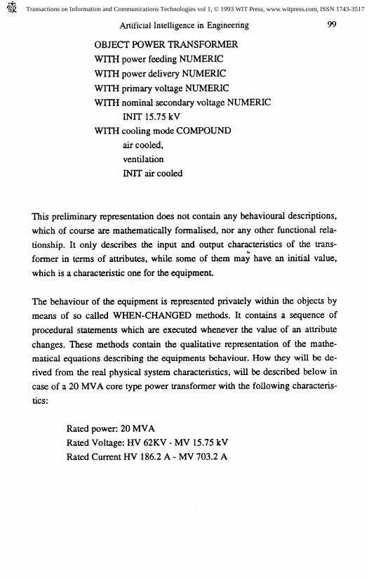
OBJECT POWER TRANSFORMER
WITH power feeding NUMERIC
WITH power delivery NUMERIC
WITH primary voltage NUMERIC
WITH nominal secondary voltage NUMERIC
INIT 15.75 kV
WITH cooling mode COMPOUND
air cooled,
ventilation
INIT air cooled
This preliminary representation does not contain any behavioural descriptions,
which of course are mathematically formalised, nor any other functional rela-
tionship. It only describes the input and output characteristics of the trans-
former in terms of attributes, while some of them may have an initial value,
which is a characteristic one for the equipment
The behaviour of the equipment is represented privately within the objects by
means of so called WHEN-CHANGED methods. It contains a sequence of
procedural statements which are executed whenever the value of an attribute
changes. These methods contain the qualitative representation of the mathe-
matical equations describing the equipments behaviour. How they will be de-
rived from the real physical system characteristics, will be described below in
case of a 20 MVA core type power transformer with the following characteris-
tics:
Rated power: 20 MVA
Rated Voltage: HV 62KV - MV 15.75 kV
Rated Current HV 186.2 A - MV 703.2 A
Transactions on Information and Communications Technologies vol 1, © 1993 WIT Press, www.witpress.com, ISSN 1743-3517
100 Artificial Intelligence in Engineering
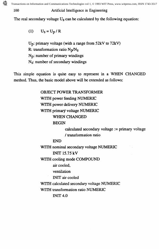
The real secondary voltage Us can be calculated by the following equation:
(1) Us = Up/R
Up: primary voltage (with a range from 52kV to 72kV)
R: transformation ratio Np/Ns
Np: number of primary windings
NS: number of secondary windings
This simple equation is quite easy to represent in a WHEN CHANGED
method. Thus, the basic model above will be extended as follows:
OBJECT POWER TRANSFORMER
WITH power feeding NUMERIC
WITH power delivery NUMERIC
WITH primary voltage NUMERIC
WHEN CHANGED
BEGIN
calculated secondary voltage := primary voltage
/ transformation ratio
END
WITH nominal secondary voltage NUMERIC
INIT 15.75 kV
WITH cooling mode COMPOUND
air cooled,
ventilation
INIT air cooled
WITH calculated secondary voltage NUMERIC
WITH transformation ratio NUMERIC
INIT 4.0
Transactions on Information and Communications Technologies vol 1, © 1993 WIT Press, www.witpress.com, ISSN 1743-3517
Artificial Intelligence in Engineering 101
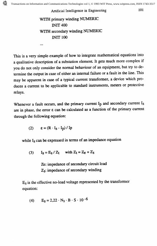
WITH primary winding NUMERIC
INIT400
WITH secondary winding NUMERIC
INIT100
This is a very simple example of how to integrate mathematical equations into
a qualitative description of a substation element It gets much more complex if
you do not only consider the normal behaviour of an equipment, but try to de-
termine the output in case of either an internal failure or a fault in the line. This
may be apparent in case of a typical current transformer, a device which pro-
duces a current to be applicable to standard instruments, meters or protective
relays.
Whenever a fault occurs, and the primary current Ip and secondary current Is
are in phase, the error e can be calculated as a function of the primary current
through the following equation:
(2) e = (
while Is can be expressed in terms of an impedance equation
(3) Is =
Ze: impedance of secondary circuit load
Z$: impedance of secondary winding
ES is the effective no-load voltage represented by the transformer
equation:
(4) Eg = 2,22 • Ns • B • S • 10^
Transactions on Information and Communications Technologies vol 1, © 1993 WIT Press, www.witpress.com, ISSN 1743-3517
102 Artificial Intelligence in Engineering
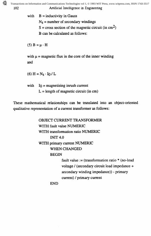
with B = induct!vity in Gauss
NS = number of secondary windings
S = cross section of the magnetic circuit (in cm̂ )
B can be calculated as follows:
(5)B=(i-H
with p = magnetic flux in the core of the inner winding
and
(6)H = Ns-IO/L
with IQ = magnetising inrush current
L = length of magnetic circuit (in cm)
These mathematical relationships can be translated into an object-oriented
qualitative representation of a current transformer as follows:
OBJECT CURRENT TRANSFORMER
WITH fault value NUMERIC
WITH transformation ratio NUMERIC
INTT4.0
WITH primary current NUMERIC
WHEN CHANGED
BEGIN
fault value := (transformation ratio * (no-load
voltage / (secondary circuit load impedance +
secondary winding impedance)) - primary
current) / primary current
END
Transactions on Information and Communications Technologies vol 1, © 1993 WIT Press, www.witpress.com, ISSN 1743-3517
Artificial Intelligence in Engineering 103
WITH no-load voltage NUMERIC
INTT140V
WITH secondary circuit load impedance NUMERIC
WITH secondary winding impedance NUMERIC
So far, only relationships which are local to the equipment have been repre-
sented in the simulation models. As described above, this is done by WHEN-
CHANGED methods. The main interest, however, is the reliable behaviour of
protection and control functions, which requires an interchange of data and or-
ders among several elements of a substation. The representation of protection
and control simulation is encapsulated in so-called "demons" which are exe-
cuted by a forward-chaining inference engine. The firing of a demon is trig-
gered whenever an attribute within its antecedent changes its value, as, for ex-
ample, when the user adjusts the parameter of an equipment, or when the value
of any parameter changes as a consequence of a WHEN-CHANGED execu-
tion.
The above calculated fault value e can be used to detect a short-circuit in the
line by the differential protection function and to send a tripping order to the
related circuit breaker. The detection of the fault is based on the calculation of
the minimum current required to trip.
(7)
with Isc = maximum short-circuit current
K = adjusting factor
On the other hand, the minimum current must have a threshold value in order
to activate a tripping order. For reliability predictive reasons, the threshold is
kept adjustable to the protection engineer.
Transactions on Information and Communications Technologies vol 1, © 1993 WIT Press, www.witpress.com, ISSN 1743-3517
104 Artificial Intelligence in Engineering
(8) I/n/n — ' Ijc
with 0 < _ _ 1
We represent this tripping threshold for the differential protective relay with
the following two demons:
DEMON short circuit detection
IF fault value OF CURRENT TRANSFORMER > 0
THEN minimum current := short-circuit current * adjusting
factor * 2 *
fault value OF CURRENT TRANSFORMER
DEMON tripping order
IF minimum current _ short-circuit current * threshold value
AND operating time _ differential protection time
characteristic
THEN tripping order := TRUE
AND position OF LINE CIRCUIT BREAKER := open
The operating time of the protection function has been introduced to adjust the
protection function parameters depending on the different architectures or
levell-leve!2 distribution of the functions. This allows the protection engineer
to "play" several alternatives by changing functions distribution, data commu-
nication channels, time characteristics, threshold values, etc. He even can
change the protection or control algorithm by rewriting the demons or adding
new ones.
In case of the differential line protection function, the time characteristic func-
tions may be adjusted by the function:
Transactions on Information and Communications Technologies vol 1, © 1993 WIT Press, www.witpress.com, ISSN 1743-3517
Artificial Intelligence in Engineering 105
(9) T = k/lb-l
where:
b = 0.02 and k = 0.13 for ANSI characteristic
b= 1.00 and k= 16.00 for Very Inverse characteristic
b = 2.00 and k = 96.00 for Extremely Inverse characteristic
IMPLEMENTATION AND RELIABILITY CALCULATION
The substation simulation software SUBSIM is implemented using
LevelSObject - PRL (Production Rule Language), which combines the object-
oriented approach to represent the physical models with a procedural language
to describe mathematical equations. It runs on a 486 PC under Microsoft Win-
dows providing the user with a fully dynamic graphical interface. Thus, the
protection engineer is able to manipulate the substation equipment parameters
and the protection and control functions by simply selecting the appropriate
icon and changing the values in several display boxes in the related pop-up
window.
The simulation is - where appropriate - running under real-time conditions.
Therefore, ten system timers can be handled in parallel in order to represent the
different operating characteristics and reaction times of the system. There also
exist two databases, one for external faults (e.g. short-circuits, ground faults,
overloads) and the other for internal equipment failures (containing the equip-
ment name, the appropriate failure mode like winding degradation, and the
failure probability, which was assessed through a previously performed
FMECA on an existing distribution substation in Portugal). The retrieval of
these databases is controlled by a random function for each, in order to get a
realistic simulation of substation operation (in case of the failure database, the
random access is adjusted by the failure probabilities).
Transactions on Information and Communications Technologies vol 1, © 1993 WIT Press, www.witpress.com, ISSN 1743-3517
106 Artificial Intelligence in Engineering
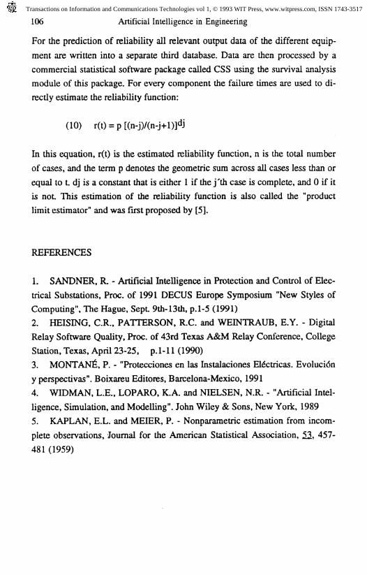
For the prediction of reliability all relevant output data of the different equip-
ment are written into a separate third database. Data are then processed by a
commercial statistical software package called CSS using the survival analysis
module of this package. For every component the failure times are used to di-
rectly estimate the reliability function:
(10)
In this equation, r(t) is the estimated reliability function, n is the total number
of cases, and the term p denotes the geometric sum across all cases less than or
equal to L dj is a constant that is either 1 if the j'th case is complete, and 0 if it
is not. This estimation of the reliability function is also called the "product
limit estimator" and was first proposed by [5].
REFERENCES
1. SANDNER, R. - Artificial Intelligence in Protection and Control of Elec-
trical Substations, Proc. of 1991 DECUS Europe Symposium "New Styles of
Computing", The Hague, Sept. 9th-13th, p.1-5 (1991)
2. HEISING, C.R., PATTERSON, R.C. and WEINTRAUB, E.Y. - Digital
Relay Software Quality, Proc. of 43rd Texas A&M Relay Conference, College
Station, Texas, April 23-25, p.1-11 (1990)
3. MONTANA, P. - "Protecciones en las Instalaciones Eldctricas. Evolucidn
y perspectivas". Boixaneu Editones, Barcelona-Mexico, 1991
4. WIDMAN, L.E., LOPARO, K.A. and NIELSEN, N.R. - "Artificial Intel-
ligence, Simulation, and Modelling". John Wiley & Sons, New York, 1989
5. KAPLAN, E.L. and MEIER, P. - Nonparametric estimation from incom-
plete observations, Journal for the American Statistical Association, 52, 457-
481 (1959)
Transactions on Information and Communications Technologies vol 1, © 1993 WIT Press, www.witpress.com, ISSN 1743-3517
Artificial Intelligence in Engineering 107
ACKNOWLEDGEMENTS
The work described is part of the ongoing project AMPERIO, funded by the
Commission of the European Community within the BRTTE/EURAM pro-
gramme under contract number BREU-0459.
Transactions on Information and Communications Technologies vol 1, © 1993 WIT Press, www.witpress.com, ISSN 1743-3517