PROCLAMATION STAGE GEOTECHNICAL REPORT TO CENTURUS ON THE PROPOSED HIGHVELD EXTENSION 49, CENTURION, INCLUDING COMMERCIAL, OFFICE AND RESIDENTIAL DEVELOPMENT. IR565 INTRACONSUL T ASSOCIATES CONSULTING ENGINEERS AND ENGINEERING GEOLOGISTS P.O. BOX 604 FOURWA YS 2055 TEL: (011) 465-8706 FAX: (011) 465-0772. REF: IR565 DECEMBER 2002
Transcript
PROCLAMATION STAGE GEOTECHNICALREPORT TO CENTURUS ON THE PROPOSEDHIGHVELD EXTENSION 49, CENTURION,INCLUDING COMMERCIAL, OFFICE ANDRESIDENTIAL DEVELOPMENT.
IR565
INTRACONSUL T ASSOCIATESCONSULTING ENGINEERS ANDENGINEERING GEOLOGISTSP.O. BOX 604FOURWA YS2055
TEL: (011) 465-8706FAX: (011) 465-0772.
REF: IR565DECEMBER 2002
Consulting Engineering Geologists & Engineers
CENTURUSP.O. BOX 3IRENE0062
ATTENTION: MR MISHA TOlKSDORFF
Intra consultIntraconsult Associates
Ground Floor Building 5Prism Business Park
Ruby Close, Corner William Nicoland Fourways Boulevard, Fourways
A PROCLAMATION STAGE GEOTECHNICAL REPORT TO CENTURUS ON THEPROPOSED HIGHVElD EXTENSION 49, CENTURION, INCLUDING COMMERCIAL,OFFICE AND RESIDENTIAL DEVELOPMENT.
SUMMARY
This report presents the results of proclamation stage geotechnical investigations carried outon the proposed Highveld Extension 49 commercial, office and residential development inCenturion. The site is located on dolomite and chert of the Monte Christo Formation,Chuniespoort Group, Transvaal Supergroup. Intrusive rocks and materials of the PretoriaDyke occur extensively under the eastern sector of the site. These investigations involved fieldinspections, a review of available data (including gravity surveys, borehole and test pit data)and completion of an infill drilling and test pitting programme.
The site was previously investigated and covered in two reports:
Intraconsult report IR482, dated 20 February 2002, entitled: "A proclamation report toCenturus on the proposed Swartland commercial and office park, Centurion."
BKS report, Reference No. P801561, dated September 1999, "Dolomite stabilityinvestigation for the proposed township Highveld Extension 34."
This report covers two areas, namely:
Area A pertaining to the commercial and office park development.
Area B covering the proposed Residential 2 and apartment area. Offices may also beerected within this designated area.
Consultant Panel: A.A. Gerber Pro Eng., B. lng. MWIM
Relevant information contained in the Intraconsult and the BKS reports has been merged intothis single report for overall planning purposes. Limited additional geophysical, drilling andbackhoe work has been undertaken. Based on the geological, geophysical andgeohydrological data gathered during this investigation the stability of the site is described interms of four D%mite Stability Zones. These Dolomite Stability Zones are defined as follows:
Dolomite Stability Zone 1:
Dolomite Stability Zone 2:
Dolomite Stability Zone 3:
Dolomite Stability Zone 4:
Area characterised as reflecting a low InherentRisk of sinkhole and doline formation withrespect to water ingress. Inherent Risk Class 1.
Area characterised as reflecting a mediumInherent Risk of sinkhole and doline formationwith respect to water ingress. Inherent RiskClass 4.
Area characterised as reflecting a high InherentRisk of small and medium size sinkhole and
doline formation with respect to water ingress.Inherent Risk Class 6.
Area characterised as reflecting a high InherentRisk of large size sinkhole and doline formationwith respect to water ingress. Inherent RiskClass 7.
Monitoring of the groundwater level in the region must form an integral part of the DolomiteRisk Management System of the local authority.
The Area A i.e. the commercial and office park area, straddles Zone 1, 2, 3 and 4 areas, andmay be utilised for the proposed land use. Detailed geotechnical investigations are required onthe footprint of each proposed structure.
The Area B i.e. Residential 2 and apartments area, straddles Zones 1 and 2 and may beplanned for proposed land use. If designed for 25 units/hectare or less, planning can proceedon the current basis of the available geotechnical data provided approval is granted by theCouncil for Geoscience and the NHBRC. If multistoried apartments are to be erected in thefuture then detailed footprint investigations are required. In addition, if office complexs areproposed, detailed geotechnical investigations will be required on the footprint area.
Appropriate water precautionary measures are provided together with recommendationsaimed at the adoption of a pro-active waterbearing services maintenance strategy. A generaldiscussion on the founding of structures and services infrastructure is given. Particularemphasis is placed upon the need to manage stormwater falling onto, moving across andexiting this site.
It is emphasised that these Dolomite Stability and soil zones are intended to provide generalguidance for the planning of this site. Detailed geotechnical investigations are required on thefootprint areas of structures in Area A and apartments or commercial structures erected withinArea B. In these instances final precautionary measures and foundation designs will bedetermined by the results of these investigations.
A PROCLAMATION STAGE GEOTECHNICAL REPORT TO CENTURUS ON THEPROPOSED HIGHVElD EXTENSION 49, CENTURION, INCLUDING COMMERCIAL,OFFICE AND RESIDENTIAL DEVELOPMENT.
SUMMARY Preface
CONTENTS
PAGE
1.
INTRODUCTION 1
2.
TERMS OF REFERENCE AND SCOPE OF WORK 1
3.
EXISTING INFORMATION 1
4.
GENERAL LOCATION AND DESCRIPTION OFTHE SITE
2
5.
PROCEDURES USED IN THESE INVESTIGATIONS 2
6.
GEOLOGY AND GEOHYDROLOGY 4
7.
DOLOMITE STABILITY CHARACTERISATION 7
8.
SOILS CLASSIFICATION 11
9.
CONCLUSIONS AND RECOMMENDATIONS 15
10.
GENERAL RECOMMENDATIONS 26
TABLES:
RISK CHARACTERISATION OF BOREHOLE DATA:HIGHVELD EXTENSION 49, CENTURION.
DRAWINGS:
PROPOSED HIGHVELD EXTENSION 49:RESIDUAL GRAVITY MAP AND BOREHOLEPOSITIONS.
This report presents and comments on the results and observations of geotechnicalinvestigations carried out on the site for the proposed Highveld Extension 49,Centurion. The report documents, the terms of reference, available data used in thestudy, investigating procedures, risk characterisation method used to zone the site,geology, geohydrology, risk zonation, soil zonation, conclusions andrecommendations. The report pertains to two distinct areas, namely:
the commercial and office park development (Area A).
the Residential 2/Apartment development (Area B). Office development may beincorporated in this particular area.
2. TERMS OF REFERENCE AND SCOPE OF WORK
The terms of reference and scope of the work to be undertaken were discussed withMr Misha Tolksdorff of Centurus. Intraconsult outlined budget and technical proposalsin letter IR482, dated 29 November 2002. Intraconsult was appointed and instructed toproceed with the investigations in accordance with these proposals by Centurus on the3 December 2002.
3. EXISTING INFORMATION
The following information has been used in the current investigation and assessmentof the site:
Intraconsult report IR482, dated 20 February 2002, entitled: "A proclamationreport to Centurus on the proposed Swartland commercial and office park,Centurion."
BKS report, Reference No. P801561, dated September 1999, "Dolomitestability investigation for the proposed township Highveld Extension 34."
Topographic map of the Director of Surveys at a scale of 1 : 50 000: Sheet2628CC, Lyttelton.
Geological Map of the GSO: Scale 1: 50 000 Sheet 2626CC Lyttelton.
"The method of scenario supposition for stability evaluation of sites on dolomiticland in South Africa." Journal Of The South African Institution Of CivilEngineers, Volume 37, Number 4, Fourth Quarter 1995.
"Proposed method for dolomite land hazard and risk assessment in SouthAfrica." accepted for publication in the Journal of the South African Institution ofCivil Engineering, August 2001.
2
National Home Builders Registration Council: Home Builders Manual: Parts 1and 2, Revision 1, February 1999.
Code of Practice: Assessment of the performance of housing units in SouthAfrica. The Joint Structural Division of SAlCE and IStructE. June 2000.
Council for Geoscience, letter G016/1/5/3, dated 20 March 2002 and entitled:"Comment on the suitability of the proposed Swartland Commercial and OfficePark, Centurion."
Council for Geoscience letter G016/1/5/3, dated 7 October 2002, entitled: "Firstcomment on the dolomite stability report for township: Highveld Extension 34.
4. GENERAL LOCATION AND DESCRIPTION OF THE SITE.
The site is located immediately south of the N1 national freeway, east of Doringkloof,west of Highveld Extension 13 and north of the proposed Olievenhoutsbosch Drive, inCenturion. The site straddles the Hennops River. The area is open and currentlyunused.
A Location Plan is provided in Figure 1.
5. PROCEDURES USED IN THESE INVESTIGATIONS
These investigations have involved the following:
5.1 Assimilation of available data.
The geotechnical reports pertaining to the two areas merged to create HighveldExtension 49 are covered in the following reports:
Intraconsult report IR482, dated 20 February 2002, entitled: "Aproclamation report to Centurus on the proposed Swartland commercialand office park, Centurion."
BKS report, Reference No. P801561, dated September 1999, "Dolomitestability investigation for the proposed township Highveld Extension 34."
These reports were commented on by the Council for Geoscience (20/3/2002and 7/10/1999).
5.2 Field Inspection
In order to develop a clearer perspective of the actual site conditions onthe area previously investigated by BKS, field inspections werecompleted during the early stages of this investigation. The object ofthese field inspections was to evaluate access, geomorphology,geology (outcrop/scattered outcrop etc), storm water runoff etc.
3
5.3 Geophysical Surveys
5.3.1 Gravity survey
Engineering and Exploration Geophysical Services undertookgeophysical surveys on the eastern site area during December 2001and the western sector during 1999. These gravity surveys wereconducted according to prevailing practice. A 30m grid was set andelevations and positions (L029) were determined using a differentialGPS. Gravity readings were taken using a Scintrex Autograv.
Data reduction followed normal procedures. Data were reduced torelative Bouguer values using an elevation correction factor of 0.21mgals/metre. A plane was fitted by regression to and then removedfrom Bouguer data set. The plane is taken to represent the regionalgravity trend and the residual gravity was derived by removing thisplane from the Bouguer data. The residual field was adjusted by aconstant after drilling data was made available, so that the values onaverage better represent depth to bedrock at the boreholes (DrawingsIR565/1 and Appendix 4).
Gravity data available from the BKS report is included on Drawing 565/1.
5.3.2 Apparent conductivity and magnetic field survey.
An apparent conductivity and magnetic field survey was carried out inthe eastern sector of the site i.e. Area B, to further assist in delineatingnorth-south striking Pretoria Dyke and related sill (See Appendix 4). AGeonics EM34-3 was used to measure the apparent conductivity. Thecoil separation was set to twenty metres and readings were taken withboth horizontal and vertical coil directions. Magnetic field readings wereat the same locations as the conductivity readings. Station positionswere recovered with the aid of a hand held GPS.
5.3 Rotary Percussion Boreholes
Thirty boreholes were previously drilled on and in the immediate area of the siteand are contained in the originallntraconsult and BKS reports.
A rotary-percussion borehole drilling programme has been carried out duringthis phase largely to confirm the lateral continuity of the sill. These boreholesalso assist in the formulation of a perspective concerning the subsurface andgeohydrological conditions on the site (Appendix 1).
All the drilling work was undertaken using a down-the-hole rotary percussion rigand a 750 c.f.m compressor delivering 250 psi to a 155mm diameter button bitor scraper. Chip samples were retrieved from the return air stream througheach metre drilled, while the penetration times per metre were recorded (whenusing the button bit) with an electronic stop watch. The retrieved samples aredescribed according to current practice.
4
The summarised borehole information gathered and recorded during theseinvestigations is provided in Tables 1 to 3. The positions of the boreholes areindicated on Drawing IR565/1. This borehole information is discussed in greaterdetail in Sections 7 and 8 below.
5.4 Trial Holes
Soil profiles were available for the area east of the Hennops River. Additionaltest pits were excavated west of the river during the current phase of work. Thetrial holes were excavated at selected positions using a 75 kW power backhoemachine. Each trial hole was entered and inspected by an engineeringgeologist who also described the soils profiles using the visual and tactileprocedures advocated by Jennings et al (1973). Each horizon of the soil profilebeing described in terms of the six descriptors, namely moisture condition,colour, consistency, structure, soil type and origin (MCCSSO). Detaileddescriptions of the trial hole profiles are given in Appendix 1 below. Theposition of each trial hole is shown on Drawings IR565/3.
5.5 Soil Sampling and Testing
For accurate classification and identification purposes, particle size distributionsand Atterberg Limit tests have been carried out on disturbed samplesrecovered from various soil type horizons encountered during theseinvestigations. Bulk samples were collected for pavement design purposes.Undisturbed block samples were cut from selected soils to determine theirpotential behavioral characteristics.
The results of these tests are fully reported on in Appendix 2 and discussed inSections 8 and 9.
6. GEOLOGY AND GEOHYDROLOGY
The site is located on dolomite and chert of the Monte Christo Formation, ChuniespoortGroup and their weathered soil derivatives. Residual dolomite (wad), chert residuumand colluvial deposits overlie the dolomite bedrock. Weathered and unweatheredsyenite of the Pretoria Dyke underlies a large portion of this site (Appendix 4).
In the eastern sector of the site the apparent conductivity and magnetic field surveywas used to better delineate the location of the intrusive sill and Pretoria Dyke. ThePretoria Dyke appears as a rectilinear on the gravity survey (Drawing IR565/1). Nogravity anomalies were detected in relation to the sill. Apart from the northerly trendingpositive gravity anomaly, the Pretoria Dyke is marked by a high amplitude magneticanomaly. Magnetic peaks mark the edges of the dyke. The eastern edge of the dyke isalso marked by a dip in vertical-dipole values, a response associated with sub verticalconductor. Here the conductor is probably a weathered contact zone. In the absenceof magnetic anomalies the extent of the syenite is inferred from zones of higherapparent conductivity. Based on the survey the potential distribution of the dyke and sillare shown on Figure 4 in Appendix 4.
5
The various lithological units encountered on the site is as follows:
LITHOLOGY LITHOSTRATIGRAPHIC UNIT
Silts, sand gravels, pedocretes
Recent deposits of mixed origin.Clayey sands
Syenite, Pretoria Dyke and sill.Clayey silts (wad) clays, sands
Chuniespoort GroupChert
Monte Christo Formation, Chuniespoort Group.Dolomite
Monte Christ Formation, Chuniespoort Group.
The most important information gathered during the drilling programme on the site is asfollows (Drawing IR565/1):
Two boreholes drilled in a north-south trending positive gravity anomalylocated in the eastern sector of the site intercept a thin colluvial horizon(3m and 1m in Boreholes 3625 and 3721 respectively) overlyingsubstantial horizons of intrusive. The intrusive typically is weatheredgrading into hard rock syenite (Boreholes 3625 and 3721, Appendix 1and Drawing IR565/1). This feature is interpreted as the Pretoria Dyke.
The majority of boreholes drilled in the broad gravity low occupying thecentral and western sector of the site located east of the river,intercepted intrusive as anticipated on Figure 4, Appendix 4:
a) A thin colluvial horizon e.g. 1m in Boreholes 4325, 4421, 4722and 5222 and 2m in Borehole 4529, overlying,
b) Weathered and hard rock intrusive. All the boreholes terminatedin intrusive rock or weathered intrusive e.g. Boreholes 15.5/6.5,17.0/1.1, H, F, 0,4325,4421,4722 and 5222, etc, Table 1 andDrawing IR482/1.
In the central area of this sector, the apparent conductivity andmagnetics show that the sill is absent. Boreholes G and 3925 confirmthis situation intercepting colluvium, alluvium chert residuum anddolomite (Table 1 and 3, Drawing IR565/1).
The eastern and western extremes of the site, east of the river areanticipated to primarily be underlain by shallow dolomite bedrock.Intrusive material or rock does not overlie the dolomite bedrock.
Boreholes 5825 shows a thin colluvial horizon directly overlyingdolomite bedrock. Borehole 28/8/14.5 at the base of the slope, showscolluvium, overlying chert and dolomite residuum and dolomite bedrockat 22m (Drawing IR565/1). Borehole 3122 intercepts a thin colluvialhorizon (1m), chert residuum and dolomite bedrock at 6m. Boreholes3423 and 3925 intercept colluvium, alluvium and dolomite bedrock. Thebedrock is intercepted at 10m in Borehole 3423 and 12 in Borehole3925.
6
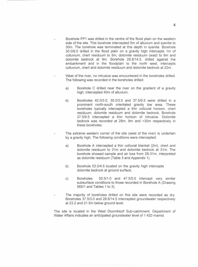
Borehole FP1 was drilled in the centre of the flood plain on the westernside of the site. This borehole intercepted 5m of alluvium and syenite to30m. The borehole was terminated at this depth in syenite. Borehole30.0/9.5 drilled in the flood plain on a gravity high intercepts 1m ofcolluvium, chert residuum to 5m, dolomite residuum (wad) to 9m anddolomite bedrock at 9m. Borehole 28.8/14.5, drilled against theembankment and in the floodplain to the north west, interceptscolluvium, chert and dolomite residuum and dolomite bedrock at 22m.
West of the river, no intrusive was encountered in the boreholes drilled.The following was recorded in the boreholes drilled:
a) Borehole C drilled near the river on the gradient of a gravityhigh, intercepted 40m of alluvium.
b) Boreholes 42.0/3.0, 35.0/3.0 and 37.5/9.5 were drilled in aprominent north-south orientated gravity low area. Theseboreholes typically intercepted a thin colluvial horizon, chertresiduum, dolomite residuum and dolomite bedrock. Borehole37.5/9.5 intercepted a thin horizon of intrusive. Dolomitebedrock was recorded at 28m, 8m and >30m respectively inthese boreholes.
The extreme western corner of the site (west of the river) is underlainby a gravity high. The following conditions were intercepted:
a) Borehole A intercepted a thin colluvial blanket (2m), chert anddolomite residuum to 31m and dolomite bedrock at 31m. Theborehole showed sample and air loss from 28-31 m, interpretedas dolomite residuum (Table 3 and Appendix 1).
b) Borehole 53.0/4.5 located on the gravity high interceptsdolomite bedrock at ground surface.
c) Boreholes 50.5/1.0 and 47.5/5.0 intercept very similarsubsurface conditions to those recorded in Borehole A (Drawing565/1 and Tables 1 to 3).
The majority of boreholes drilled on this site were recorded as dry.Boreholes 37.5/3.0 and 28.8/14.5 intercepted groundwater respectivelyat 23.2 and 21.5m below ground level.
The site is located in the West Doornkloof Sub-catchment. Department ofWater Affairs indicates an anticipated groundwater level of 1 420 mamsl.
7
7. DOLOMITE STABILITY CHARACTERISATION
(Refer Tables 1 to 3 and Appendix 1).
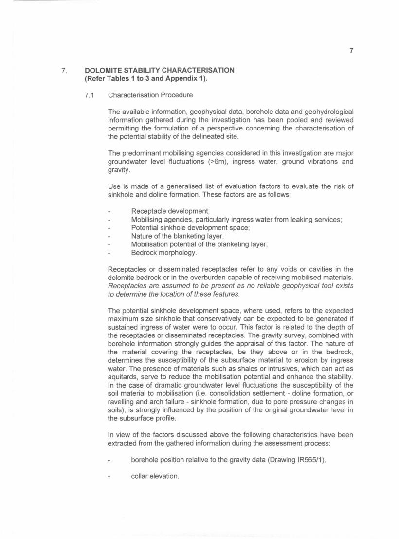
7.1 Characterisation Procedure
The available information, geophysical data, borehole data and geohydrologicalinformation gathered during the investigation has been pooled and reviewedpermitting the formulation of a perspective concerning the characterisation ofthe potential stability of the delineated site.
The predominant mobilising agencies considered in this investigation are majorgroundwater level fluctuations (>6m), ingress water, ground vibrations andgravity.
Use is made of a generalised list of evaluation factors to evaluate the risk ofsinkhole and doline formation. These factors are as follows:
Receptacle development;Mobilising agencies, particularly ingress water from leaking services;Potential sinkhole development space;Nature of the blanketing layer;Mobilisation potential of the blanketing layer;Bedrock morphology.
Receptacles or disseminated receptacles refer to any voids or cavities in thedolomite bedrock or in the overburden capable of receiving mobilised materials.Receptacles are assumed to be present as no reliable geophysical tool existsto determine the location of these features.
The potential sinkhole development space, where used, refers to the expectedmaximum size sinkhole that conservatively can be expected to be generated ifsustained ingress of water were to occur. This factor is related to the depth ofthe receptacles or disseminated receptacles. The gravity survey, combined withborehole information strongly guides the appraisal of this factor. The nature ofthe material covering the receptacles, be they above or in the bedrock,determines the susceptibility of the subsurface material to erosion by ingresswater. The presence of materials such as shales or intrusives, which can act asaquitards, serve to reduce the mobilisation potential and enhance the stability.In the case of dramatic groundwater level fluctuations the susceptibility of thesoil material to mobilisation (Le. consolidation settlement - doline formation, orravelling and arch failure - sinkhole formation, due to pore pressure changes insoils), is strongly influenced by the position of the original groundwater level inthe subsurface profile.
In view of the factors discussed above the following characteristics have beenextracted from the gathered information during the assessment process:
borehole position relative to the gravity data (Drawing IR565/1).
collar elevation.
depth to present groundwater level.
depth to dolomite bedrock.
depth to potential receptacles (Tables 1 to 3).
8
nature and thickness of blanketing layer i.e. material type, penetrationtimes, etc (Tables 1 to 3).
position of the bedrock with respect to the groundwater level.
thickness and nature of the soil materials above the groundwater level(original) i.e. type soil and potential geotechnical characteristics.
thickness and nature of the soil materials below the presentgroundwater level.
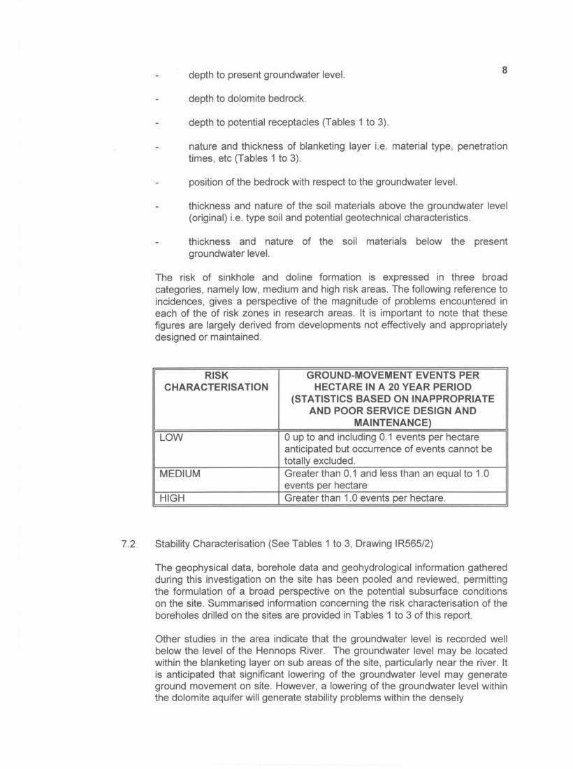
The risk of sinkhole and doline formation is expressed in three broadcategories, namely low, medium and high risk areas. The following reference toincidences, gives a perspective of the magnitude of problems encountered ineach of the of risk zones in research areas. It is important to note that thesefigures are largely derived from developments not effectively and appropriatelydesigned or maintained.
RISK GROUND-MOVEMENT EVENTS PERCHARACTERISATION
HECTARE IN A 20 YEAR PERIOD
(STATISTICS BASED ON INAPPROPRIATEAND POOR SERVICE DESIGN ANDMAINTENANCE)LOWo up to and including 0.1 events per hectare
anticipated but occurrence of events cannot betotally excluded.MEDIUMGreater than 0.1 and less than an equal to 1.0
events per hectareHIGHGreater than 1.0 events per hectare.
7.2 Stability Characterisation (See Tables 1 to 3, Drawing IR565/2)
The geophysical data, borehole data and geohydrological information gatheredduring this investigation on the site has been pooled and reviewed, permittingthe formulation of a broad perspective on the potential subsurface conditionson the site. Summarised information concerning the risk characterisation of theboreholes drilled on the sites are provided in Tables 1 to 3 of this report.
Other studies in the area indicate that the groundwater level is recorded wellbelow the level of the Hennops River. The groundwater level may be locatedwithin the blanketing layer on sub areas of the site, particularly near the river. Itis anticipated that significant lowering of the groundwater level may generateground movement on site. However, a lowering of the groundwater level withinthe dolomite aquifer will generate stability problems within the densely
9
developed Centurion area. The Department of Water Affairs constantlymonitors groundwater levels in the region. It is essential that the local authorityplace pro-active groundwater level monitoring on its Dolomite RiskManagement Strategy.
Based on the geological, geophysical and geohydrological data gatheredduring this investigation the stability of the various sites are described in termsof three Dolomite Stability Zones. These Dolomite Stability Zones are definedas follows:
Dolomite Stabilitv Zone 1: Area characterised as reflecting a low Inherent Riskof sinkhole and doline formation with respect to water ingress. Inherent RiskClass 1.
This zone is typically underlain by the following conditions:
Gravity high and plain area.
Area indicated by apparent conductivity and magnetic field as beingunderlain by dyke and sill.
Boreholes typically intercept a thin colluvial horizon e.g. 3m in Borehole3625, 1m to 2m in Boreholes 4722, 4421, 4529, F, 0, 15.5/6.5 and17.0/1.1, etc.
Alluvium is encountered in boreholes on the site. In this zone Borehole
4020 intercepts 9m of alluvium.
Substantial thicknesses of intrusive material is intercepted in theboreholes drilled e.g. in excess of 21m in Borehole 17.0/1.1, in excessof 28m in Boreholes 15.5/6.5, H, 4325 and 4722, 4421 and 5222, inexcess of 30-40m in Boreholes 0, E, F (Appendix 1, Table 1 andDrawing IR482/1).
Hard rock intrusive is intercepted in certain boreholes e.g. at 20 to 30min Borehole 3625, 30 to 40m in Borehole 0 and at 27m in Borehole3721.
The boreholes drilled are dry. However, perched groundwaterconditions are anticipated to develop during wet seasons on theintrusive which may act as an aquitard.
Intrusive material related to the Pretoria Dyke blankets potentialreceptacles located at depth. These materials are anticipated toenhance the stability, acting as an aquitard, retarding ingress of water,assisting in precluding subsurface erosion and sinkhole formation.Where alluvium overlies the intrusive the transported material isanticipated to further enhance the stability, reinforcing a low mobilisationpotential for the zone. Where the intrusive material is laterallydiscontinuous, the potential for subsurface erosion will increase. ThePDS is taken as large with bedrock depths at 27 to 34m.