12
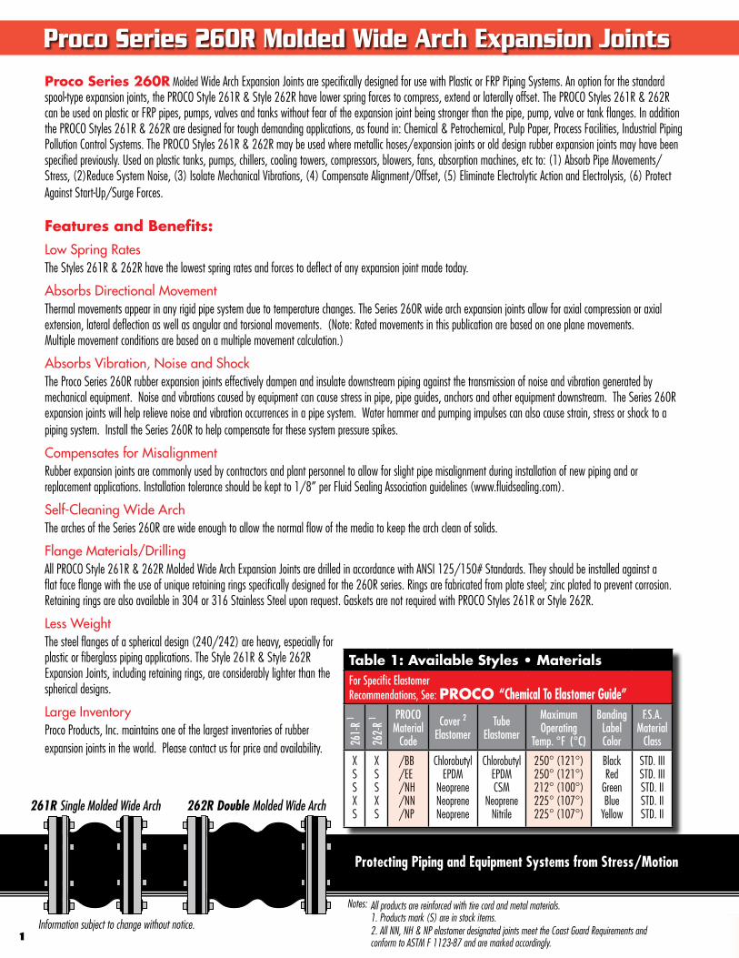
Proco Series 260R Molded Wide Arch Expansion Joints are specifically designed for use with Plastic or FRP Piping Systems. An option for the standard spool-type expansion joints, the PROCO Style 261R & Style 262R have lower spring forces to compress, extend or laterally offset. The PROCO Styles 261R & 262R can be used on plastic or FRP pipes, pumps, valves and tanks without fear of the expansion joint being stronger than the pipe, pump, valve or tank flanges. In addition the PROCO Styles 261R & 262R are designed for tough demanding applications, as found in: Chemical & Petrochemical, Pulp Paper, Process Facilities, Industrial Piping Pollution Control Systems. The PROCO Styles 261R & 262R may be used where metallic hoses/expansion joints or old design rubber expansion joints may have been specified previously. Used on plastic tanks, pumps, chillers, cooling towers, compressors, blowers, fans, absorption machines, etc to: (1) Absorb Pipe Movements/Stress, (2)Reduce System Noise, (3) Isolate Mechanical Vibrations, (4) Compensate Alignment/Offset, (5) Eliminate Electrolytic Action and Electrolysis, (6) Protect Against Start-Up/Surge Forces.
Features and Benefits:Low Spring RatesThe Styles 261R & 262R have the lowest spring rates and forces to deflect of any expansion joint made today.
Absorbs Directional MovementThermal movements appear in any rigid pipe system due to temperature changes. The Series 260R wide arch expansion joints allow for axial compression or axial extension, lateral deflection as well as angular and torsional movements. (Note: Rated movements in this publication are based on one plane movements. Multiple movement conditions are based on a multiple movement calculation.)
Absorbs Vibration, Noise and ShockThe Proco Series 260R rubber expansion joints effectively dampen and insulate downstream piping against the transmission of noise and vibration generated by mechanical equipment. Noise and vibrations caused by equipment can cause stress in pipe, pipe guides, anchors and other equipment downstream. The Series 260R expansion joints will help relieve noise and vibration occurrences in a pipe system. Water hammer and pumping impulses can also cause strain, stress or shock to a piping system. Install the Series 260R to help compensate for these system pressure spikes.
Compensates for MisalignmentRubber expansion joints are commonly used by contractors and plant personnel to allow for slight pipe misalignment during installation of new piping and or replacement applications. Installation tolerance should be kept to 1/8” per Fluid Sealing Association guidelines (www.fluidsealing.com).
Self-Cleaning Wide ArchThe arches of the Series 260R are wide enough to allow the normal flow of the media to keep the arch clean of solids.
Flange Materials/DrillingAll PROCO Style 261R & 262R Molded Wide Arch Expansion Joints are drilled in accordance with ANSI 125/150# Standards. They should be installed against a flat face flange with the use of unique retaining rings specifically designed for the 260R series. Rings are fabricated from plate steel; zinc plated to prevent corrosion. Retaining rings are also available in 304 or 316 Stainless Steel upon request. Gaskets are not required with PROCO Styles 261R or Style 262R.
Less WeightThe steel flanges of a spherical design (240/242) are heavy, especially for plastic or fiberglass piping applications. The Style 261R & Style 262R Expansion Joints, including retaining rings, are considerably lighter than the spherical designs.
Large InventoryProco Products, Inc. maintains one of the largest inventories of rubber expansion joints in the world. Please contact us for price and availability.
Information subject to change without notice.
Protecting Piping and Equipment Systems from Stress/Motion
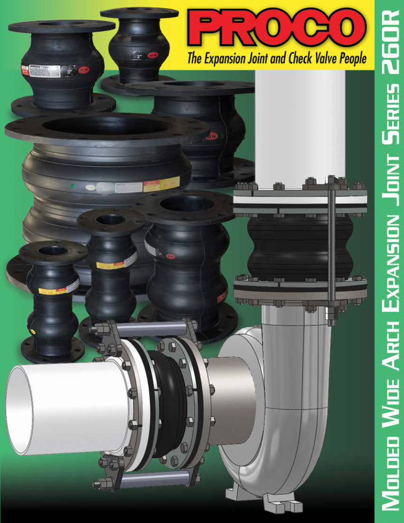
Proco Series 260R Molded Wide Arch Expansion Joints
1
All products are reinforced with tire cord and metal materials.1. Products mark (S) are in stock items.2. All NN, NH & NP elastomer designated joints meet the Coast Guard Requirements and conform to ASTM F 1123-87 and are marked accordingly.
Notes:
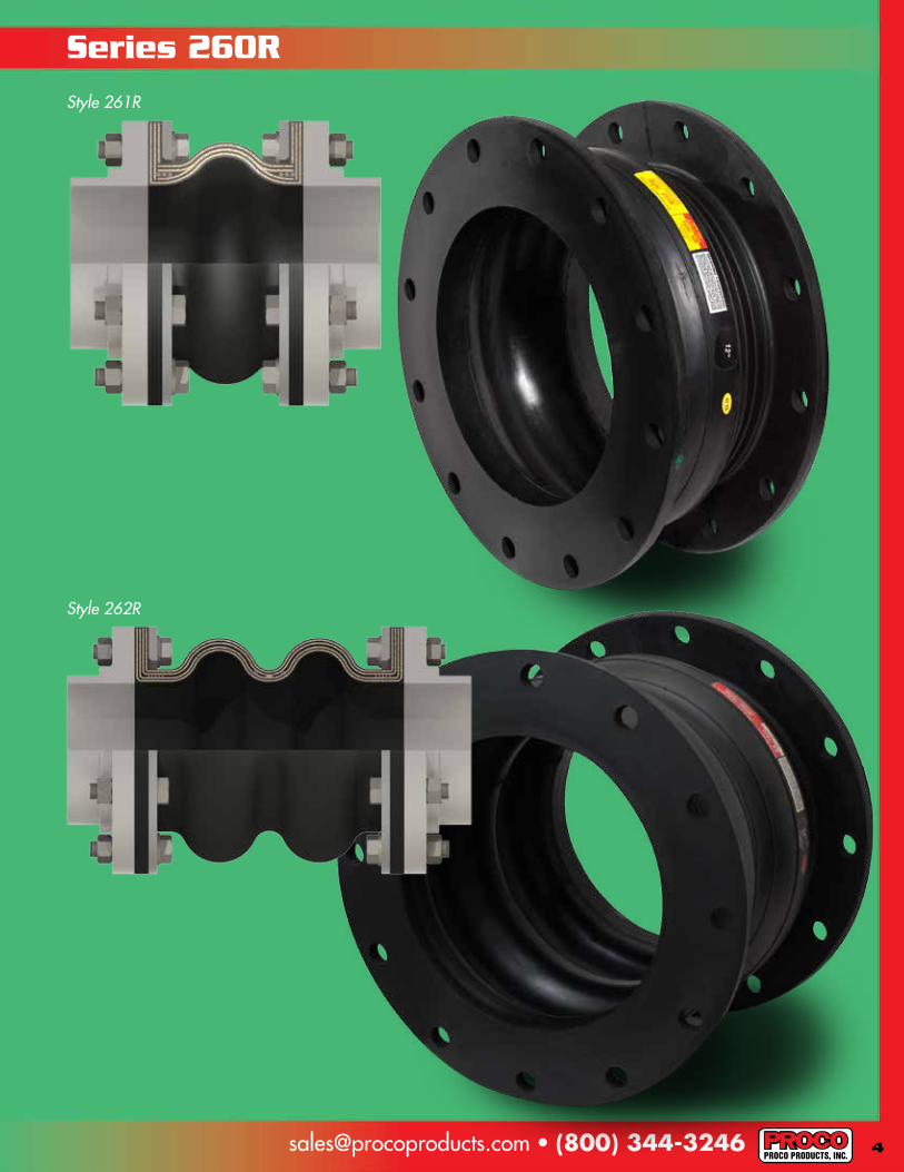
261R Single Molded Wide Arch 262R Double Molded Wide Arch
Table 1: Available Styles • MaterialsFor Specific ElastomerRecommendations, See: PROCO “Chemical To Elastomer Guide”
261-
R 1
262-
R 1 PROCO
Material Code
Cover 2Elastomer
Tube Elastomer
Maximum Operating
Temp. °F (°C)
BandingLabelColor
F.S.A.Material
Class
XSSXS
XS SXS
/BB /EE /NH/NN/NP
Chlorobutyl EPDM
NeopreneNeoprene Neoprene
Chlorobutyl EPDM CSM
Neoprene Nitrile
250° (121°)250° (121°)212° (100°)225° (107°)225° (107°)
BlackRed
GreenBlue
Yellow
STD. IIISTD. IIISTD. IISTD. IISTD. II
[email protected] • (800) 344-3246
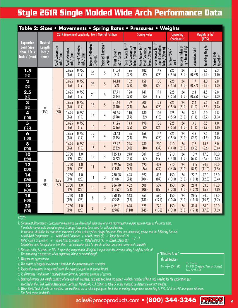
Table 2: Sizes • Movements • Spring Rates • Pressures • Weights
Expansion Joint Size
Nom. I.D. x Inch / (mm)
NeutralLengthInch / (mm)
261R Movement Capability: From Neutral Position 1 Spring Rates Operating Conditions 2
Weights in lbs3
(KGS)
Axial
Comp
ressi
onIn
ch /
(mm)
Axial
Exten
sion
Inch
/ (m
m)
Later
al De
flecti
onIn
ch /
(mm)
Angu
lar D
eflec
tion 4
(Deg
rees
)
Torsi
onal
Rotat
ion 5
(Deg
rees
)
Thru
st Fa
ctor 6
In2
/ (cm
2)
Force
Poun
ds fo
r 1”
Axial
Comp
ressi
onlb/
in /
(N/m
m)
Force
Poun
ds fo
r 1”
Axial
Exten
sion
lb/in
/ (N
/mm)
Force
Poun
ds fo
r 1”
Later
al De
flecti
onlb/
in /
(N/m
m)
Posit
ive PS
IG /
(B
ar)
Vacu
um In
ches
of
Hg /
(mm
of H
g)
Expa
nsion
Joint
Retai
ning R
ing Se
t
Cont
rol U
nit
Asse
mbly
7
1.5(40)
6(150)
1.5(38)
0.625(16)
0.750(19) 28 5
11.04 (71)
126(22)
182(32)
149(26)
225 (15.5)
24 (610)
1.3(0.59)
2.5(1.1)
2.3(1.0)
2(50)
0.625(16)
0.750(19) 25 5
14.18(92)
132(23)
158(28)
130(23)
225 (15.5)
24 (610)
1.7(0.77)
4.0(1.8)
2.8(1.3)
2.5(65)
0.625(16)
0.750(19) 20 5
17.71(114)
128(22)
141(25)
111(19)
225 (15.5)
24 (610)
2.1(0.95)
4.5(2.0)
2.8(1.3)
3(80)
0.625(16)
0.750(19) 18 5
21.64 (140)
139(24)
208(36)
133(23)
225 (15.5)
24 (610)
2.4(1.0)
5.5(2.5)
2.8(1.3)
4(100)
0.625(16)
0.750(19) 14 4
30.66(198)
110(19)
180(32)
105(18)
225 (15.5)
24 (610)
3.2(1.4)
6.0(2.7)
2.8(1.3)
5(125)
0.625(16)
0.750(19) 13 4
41.26(266)
143(25)
190(33)
136(24)
225 (15.5)
24 (610)
3.6(1.6)
8.5(3.9)
4.0(1.8)
6(150)
0.625(16)
0.750(19) 12 4
53.43(345)
136(24)
166(29)
147(26)
225 (15.5)
24 (610)
4.9(2.2)
9.5(4.3)
4.0(1.8)
8(200)
0.625(16)
0.750(19) 12 4
82.47(532)
226(40)
230(40)
210(37)
210 (14.8)
24 (610)
7.7(3.5)
14.5(6.6)
8.0(3.6)
10(250)
8(200)
2.25(57)
0.750(19)
1.0(25) 12 4
135.13(872)
248(43)
381(67)
281(49)
210 (14.8)
24 (610)
13.9(6.3)
17.0(7.7)
10.0(4.5)
12(300)
0.750(19)
1.0(25) 11 4
179.46(1158)
378(66)
493(86)
409(72)
210 (14.8)
24 (610)
19.5(8.8)
24.5(11.0)
10.0(4.5)
14(350)
0.750(19)
1.0(25) 11 3
230.08(1484)
423(74)
592(104)
497(87)
150 (10.3)
24 (610)
22.7(10.3)
27.0(12.3)
12.0(5.4)
16(400)
0.750(19)
1.0(25) 10 3
286.98(1852)
432(74)
606(106)
509(89)
150 (10.3)
24 (610)
26.8(12.2)
33.5(15.3)
15.0(6.8)
18(450)
0.750(19)
1.0(25) 8 3
350.15(2259)
543(95)
761(133)
690(121)
150 (10.3)
24 (610)
29.5(13.4)
34.0(15.5)
16.0(7.2)
20(500)
0.750(19)
1.0(25) 8 3
419.61(2707)
628(110)
829(145)
776(136)
150 (10.3)
24 (610)
31.8(17.3)
38.0(17.3)
16.0(7.2)
2
Style 261R Single Molded Wide Arch Performance Data
NOTES:1. Concurrent Movements - Concurrent movements are developed when two or more movements in a pipe system occur at the same time. If multiple movements exceed single arch design there may be a need for additional arches. To perform calculation for concurrent movement when a pipe system design has more than one movement, please use the following formula: Actual Axial Compression + Actual Axial Extension + Actual Lateral (X) + Actual Lateral (Y) = / <1 Rated Axial Compression + Rated Axial Extension + Rated Lateral (X) + Rated Lateral (Y) Calculation must be equal to or less than 1 for expansion joint to operate within concurrent movement capability.2. Pressure rating is based on 194°F operating temperature. At higher temperature the pressure rating is slightly reduced. Vacuum rating is expressed when expansion joint is at neutral length.3. Weights are approximate. 4. The degree of angular movement is based on the maximum rated extension.5. Torsional movement is expressed when the expansion joint is at neutral length.6. To determine “end thrust,” multiply thrust factor by operating pressure of system. 7. Limit rod control unit weight consists of one rod with washers, nuts and two limit rod plates. Multiply number of limit rods needed for the application (as specified in the Fluid Sealing Association’s Technical Handbook, 7.3 Edition or table 5 in this manual) to determine correct weights.8. When limit/Control Units are required, use additional set of retaining rings on back side of mating flange when connecting to PVC, CPVC or FRP to improve stiffness. See back cover for details.
Thrust Factor=“Effective Area”
3
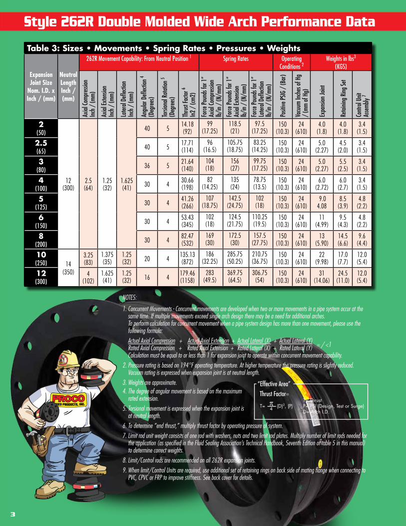
Style 262R Double Molded Wide Arch Performance Data
Table 3: Sizes • Movements • Spring Rates • Pressures • Weights
Expansion Joint Size
Nom. I.D. x Inch / (mm)
NeutralLengthInch / (mm)
262R Movement Capability: From Neutral Position 1 Spring Rates Operating Conditions 2
Weights in lbs3
(KGS)
Axial
Comp
ressi
onIn
ch /
(mm)
Axial
Exten
sion
Inch
/ (m
m)
Later
al De
flecti
onIn
ch /
(mm)
Angu
lar D
eflec
tion 4
(Deg
rees
)
Torsi
onal
Rotat
ion 5
(Deg
rees
)
Thru
st Fa
ctor 6
In2
/ (cm
2)
Force
Poun
ds fo
r 1”
Axial
Comp
ressi
onlb/
in /
(N/m
m)
Force
Poun
ds fo
r 1”
Axial
Exten
sion
lb/in
/ (N
/mm)
Force
Poun
ds fo
r 1”
Later
al De
flecti
onlb/
in /
(N/m
m)
Posit
ive PS
IG /
(Bar
)
Vacu
um In
ches
of H
g /
(mm
of H
g)
Expa
nsion
Joint
Retai
ning R
ing Se
t
Cont
rol U
nit
Asse
mbly
7
2(50)
12(300)
2.5(64)
1.25(32)
1.625(41)
40 514.18(92)
99(17.25)
118.5(21)
97.5(17.25)
150 (10.3)
24 (610)
4.0(1.8)
4.0(1.8)
3.4(1.5)
2.5(65)
40 517.71(114)
96(16.5)
105.75(18.75)
83.25(14.25)
150 (10.3)
24 (610)
5.0(2.27)
4.5(2.0)
3.4(1.5)
3(80)
36 521.64 (140)
104(18)
156(27)
99.75(17.25)
150 (10.3)
24 (610)
5.0(2.27)
5.5(2.5)
3.4(1.5)
4(100)
30 430.66(198)
82(14.25)
135(24)
78.75(13.5)
150 (10.3)
24 (610)
6.0(2.72)
6.0(2.7)
3.4(1.5)
5(125)
30 441.26(266)
107(18.75)
142.5(24.75)
102(18)
150 (10.3)
24 (610)
9.04.08
8.5(3.9)
4.8(2.2)
6(150)
30 453.43(345)
102(18)
124.5(21.75)
110.25(19.5)
150 (10.3)
24 (610)
11(4.99)
9.5(4.3)
4.8(2.2)
8(200)
30 482.47(532)
169(30)
172.5(30)
157.5(27.75)
150 (10.3)
24 (610)
13(5.90)
14.5(6.6)
9.6(4.4)
10(250) 14
(350)
3.25(83)
1.375(35)
1.25(32) 20 4
135.13(872)
186(32.25)
285.75(50.25)
210.75(36.75)
150 (10.3)
24 (610)
22(9.98)
17.0(7.7)
12.0(5.4)
12(300)
4(102)
1.625(41)
1.25(32) 16 4
179.46(1158)
283(49.5)
369.75(64.5)
306.75(54)
150 (10.3)
24 (610)
31(14.06)
24.5(11.0)
12.0(5.4)
NOTES:
1. Concurrent Movements - Concurrent movements are developed when two or more movements in a pipe system occur at the same time. If multiple movements exceed single arch design there may be a need for additional arches. To perform calculation for concurrent movement when a pipe system design has more than one movement, please use the following formula: Actual Axial Compression + Actual Axial Extension + Actual Lateral (X) + Actual Lateral (Y) = / <1 Rated Axial Compression + Rated Axial Extension + Rated Lateral (X) + Rated Lateral (Y) Calculation must be equal to or less than 1 for expansion joint to operate within concurrent movement capability.2. Pressure rating is based on 194°F operating temperature. At higher temperature the pressure rating is slightly reduced. Vacuum rating is expressed when expansion joint is at neutral length.3. Weights are approximate. 4. The degree of angular movement is based on the maximum rated extension.5. Torsional movement is expressed when the expansion joint is at neutral length.6. To determine “end thrust,” multiply thrust factor by operating pressure of system. 7. Limit rod unit weight consists of one rod with washers, nuts and two limit rod plates. Multiply number of limit rods needed for the application (as specified in the Fluid Sealing Association’s Technical Handbook, Seventh Edition or table 5 in this manual) to determine correct weights.8. Limit/Control rods are recommended on all 262R expansion joints.9. When limit/Control Units are required, use additional set of retaining rings on back side of mating flange when connecting to PVC, CPVC or FRP to improve stiffness. See back cover for details.
Thrust Factor=“Effective Area”
5
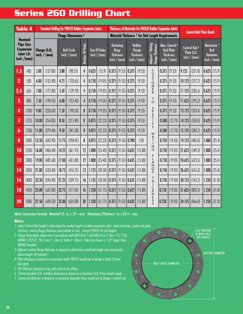
Series 260 Drilling Chart
Table 4 Standard Drilling for PROCO Rubber Expansion Joints Thickness of Materials for PROCO Rubber Expansion JointsControl Unit Plate Detail
Nominal Pipe Size Expansion Joint I.D.
Inch /(mm)
Flange Dimensions 2 Material Thickness 1 for Bolt Length Requirements
Flange O.D.Inch / (mm)
Bolt CircleInch / (mm)
Numb
er O
f Hole
s
Size Of HolesInch / (mm)
Retaining Rings
Thickness Inch / (mm)
Rubber Flange
ThicknessInch / (mm)
Adjac
ent 3 M
ating
Fla
nge T
hickn
ess Max. Control 4
Rod Plate Thickness
Inch / (mm)
Control Rod 6Plate O.D.
Inch / (mm)
Maximum 7
Rod Diameter
Inch / (mm)
1.5 (40) 5.00 (127.00) 3.88 (98.55) 4 0.625 (15.9) 0.375 (9.53) 0.375 (9.53) CUSTOMER
TO SPECIFY
MATING
FLANGE THICKNESS
0.375 (9.53) 9.125 (231.8) 0.625 (15.9)
2 (50) 6.00 (152.40) 4.75 (120.65) 4 0.750 (19.05) 0.375 (9.53) 0.375 (9.53) 0.375 (9.53) 10.125 (257.2) 0.625 (15.9)
2.5 (65) 7.00 (177.80) 5.50 (139.70) 4 0.750 (19.05) 0.375 (9.53) 0.375 (9.53) 0.375 (9.53) 11.125 (282.6) 0.625 (15.9)
3 (80) 7.50 (190.50) 6.00 (152.40) 4 0.750 (19.05) 0.375 (9.53) 0.375 (9.53) 0.375 (9.53) 11.625 (295.3) 0.625 (15.9)
4 (100) 9.00 (228.60) 7.50 (190.50) 8 0.750 (19.05) 0.375 (9.53) 0.375 (9.53) 0.375 (9.53) 13.125 (333.4) 0.625 (15.9)
5 (125) 10.00 (254.00) 8.50 (215.90) 8 0.875 (22.23) 0.375 (9.53) 0.375 (9.53) 0.500 (12.70) 14.125 (358.8) 0.625 (15.9)
6 (150) 11.00 (279.40) 9.50 (241.30) 8 0.875 (22.23) 0.375 (9.53) 0.375 (9.53) 0.500 (12.70) 15.125 (384.2) 0.625 (15.9)
8 (200) 13.50 (342.90) 11.75 (298.45) 8 0.875 (22.23) 0.375 (9.53) 0.390 (10) 0.750 (19.05) 19.125 (485.8) 1.000 (25.4)
10 (250) 16.00 (406.40) 14.25 (361.95) 12 1.000 (25.40) 0.375 (9.53) 0.625 (15.88) 0.750 (19.05) 21.625 (549.3) 1.000 (25.4)
12 (300) 19.00 (482.60) 17.00 (431.80) 12 1.000 (25.40) 0.375 (9.53) 0.625 (15.88) 0.750 (19.05) 24.625 (625.5) 1.000 (25.4)
14 (350) 21.00 (533.40) 18.75 (476.25) 12 1.125 (28.58) 0.375 (9.53) 0.625 (15.88) 0.750 (19.05) 26.625 (676.3) 1.000 (25.4)
16 (400) 23.50 (596.90) 21.25 (539.75) 16 1.125 (28.58) 0.375 (9.53) 0.625 (15.88) 0.750 (19.05) 30.125 (765.2) 1.250 (31.8)
18 (450) 25.00 (635.00) 22.75 (577.85) 16 1.250 (31.75) 0.375 (9.53) 0.625 (15.88) 0.750 (19.05) 31.625 (803.3) 1.250 (31.8)
20 (500) 27.50 (698.50) 25.00 (635.00) 20 1.250 (31.75) 0.375 (9.53) 0.625 (15.88) 0.750 (19.05) 34.125 (866.8) 1.250 (31.8)
Metric Conversion Formula: Nominal I.D.: in. x 25 = mm; Dimensions/Thickness’: in. x 25.4 = mm. Notes:1. Limit/Control Rod length is determined by neutral length of rubber expansion joint, rated extension, control rod plate thickness, mating flange thickness and number of nuts. Consult PROCO for rod lengths. 2. Flange Dimensions shown are in accordance with ANSI B16.1 and ANSI B16.5 Class 125/150, AWWA C-207-07, Tbl 2 and 3 - Class D, Table 4 - Class E. Hole size shown is 1/8” larger than AWWA Standard. 3. Adjacent mating flange thickness is required to determine overall rod length and compression sleeve length (if required). 4. Plate thickness is based on a maximum width PROCO would use to design a Limit/Control Rod plate.5. Flat Washers required at ring splits and are by others.6. Control rod plate O.D. installed dimension is based on a maximum O.D. Proco would supply.7. Control rod diameter is based on a maximum diameter Proco would use to design a control rod.
[email protected] • (800) 344-3246
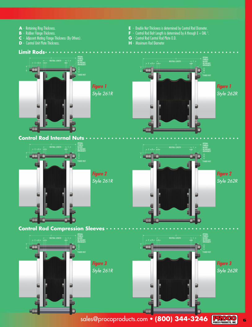
A - Retaining Ring Thickness.B - Rubber Flange Thickness.C - Adjacent Mating Flange Thickness (By Others).D - Control Unit Plate Thickness.
E - Double Nut Thickness is determined by Control Rod Diameter.F - Control Rod Bolt Length is determined by A through E + OAL 1.G - Control Rod Control Rod Plate O.D.H - Maximum Rod Diameter
Figure 1
Figure 2
Figure 3
Figure 1
Figure 2
Figure 3
Style 261R
Style 261R
Style 261R
Style 262R
Style 262R
Style 262R
Limit Rods
Control Rod Internal Nuts
Control Rod Compression Sleeves
7
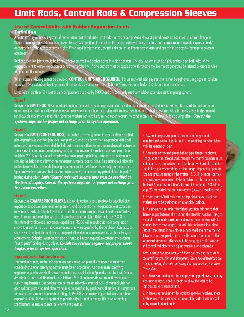
Limit Rods, Control Rods & Compression SleevesUse of Control Units with Rubber Expansion JointsDefinitionA control unit assembly is a system of two or more control rod units (limit rods, tie rods or compression sleeves) placed across an expansion joint from flange to flange to minimize possible damage caused by excessive motion of a pipeline. The control unit assemblies can be set at the maximum allowable expansion and/or contraction of the rubber expansion joint. When used in this manner, control units are an additional safety factor and can minimize possible damage to adjacent equipment.
Rubber expansion joints should be installed between two fixed anchor points in a piping system. The pipe system must be rigidly anchored on both sides of the expansion joint to control expansion or contraction of the line. Piping anchors must be capable of withstanding the line thrusts generated by internal pressure or wide temperature fluctuations.
When proper anchoring cannot be provided, CONTROL UNITS ARE REQUIRED. For un-anchored piping systems nuts shall be tightened snug against rod plate to prevent over extension due to pressure thrust created by expansion joint. Refer to “Thrust Factor in Tables 2 & 3, note 6 in this manual.
Listed below are three (3) control unit configurations supplied by PROCO and are commonly used with rubber expansion joints in piping systems.
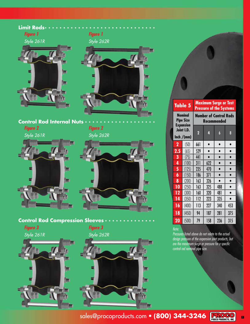
Figure 1Known as a LIMIT ROD, this control unit configuration will allow an expansion joint to extend to a predetermined extension setting. Nuts shall be field set to no more than the maximum allowable extension movement of a rubber expansion joint (unless used in an un-anchored system). Refer to Tables 2 & 3 in this manual for allowable movement capabilities. Spherical washers can also be furnished (upon request) to combat any “nut to plate” binding during offset. Consult the systems engineer for proper nut settings prior to system operation.
Figure 2Known as a LIMIT/CONTROL ROD, this control unit configuration is used to allow specified pipe expansion (expansion joint axial compression) and pipe contraction (expansion joint axial extension) movements. Nuts shall be field set to no more than the maximum allowable extension (unless used in an un-anchored pipe system) or compression of a rubber expansion joint. Refer to Tables 2 & 3 in this manual for allowable movement capabilities. Internal and external nuts can also be field set to allow for no movement in the horizontal plane. This setting will allow the rubber to move laterally while keeping expansion joint thrust forces low on adjacent equipment. Spherical washers can also be furnished (upon request) to combat any potential “nut to plate” binding during offset. Limit/Control rods with internal nuts must be specified at the time of inquiry. Consult the systems engineer for proper nut settings prior to system operation.
Figure 3 Known as a COMPRESSION SLEEVE, this configuration is used to allow for specified pipe expansion (expansion joint axial compression) and pipe contraction (expansion joint extension) movements. Nuts shall be field set to no more than the maximum allowable extension (unless used in an un-anchored pipe system) of a rubber expansion joint. Refer to Tables 2 & 3 in this manual for allowable movement capabilities. PROCO will manufacture each compression sleeve to allow for no axial movement unless otherwise specified by the purchaser. Compression sleeves shall be field trimmed to meet required allowable axial movement as set forth by system requirements. Spherical washers can also be furnished (upon request) to combat any potential “nut to plate” binding during offset. Consult the systems engineer for proper sleeve lengths prior to system operation.
Important Control Unit Considerations The number of rods, control rod diameters and control rod plate thicknesses are important considerations when specifying control units for an application. As a minimum, specifying engineers or purchasers shall follow the guidelines as set forth in Appendix C of the Fluid Sealing Association’s Technical Handbook, 7.3 Edition. PROCO engineers its control unit assemblies to system requirements. Our designs incorporate an allowable stress of 65% of material yield for each rod and plate (rod and plate material to be specified by purchaser). Therefore, it is important to provide pressure and temperature ratings to PROCO when requesting control units for rubber expansion joints. It is also important to provide adjacent mating flange thickness or mating specifications to ensure correct rod lengths are provided.
Installation Instructions for Control Rods1. Assemble expansion joint between pipe flanges in its manufactured neutral length. Install the retaining rings furnished with the expansion joint.
2. Assemble control rod plates behind pipe flanges as shown. Flange bolts or all thread studs through the control rod plate must be longer to accommodate the plate thickness. Control rod plates should be equally spaced around the flange. Depending upon the size and pressure rating of the system, 2, 3, 4, or more control/limit rods may be required. Refer to Table 5 in this manual or to the Fluid Sealing Association’s Technical Handbook, 7.3 Edition, page 23 for control rod pressure ratings (www.fluidsealing.com).
3. Insert control/limit rods through top plate holes. Steel flat washers are to be positioned at outer plate surface.
4. If a single nut per unit is furnished, position this nut so that there is a gap between the nut and the steel flat washer. This gap is equal to the joints maximum extension (commencing with the nominal face-to-face length). To lock this nut in position, either “stake” the thread in two places or tack weld the nut to the rod. If two nuts are supplied, the nuts will create a “jamming” effect to prevent loosening. (Nuts should be snug against flat washer and control rod plate when piping system is un-anchored.)
Note: Consult the manufacturer if there are any questions as to the rated compression and elongation. These two dimensions are critical in setting the nuts and sizing the compression pipe sleeve (if supplied).
5. If there is a requirement for compression pipe sleeves, ordinary pipe may be used, sized in length to allow the joint to be compressed to its normal limit.
6. If there is a requirement for optional spherical washers, these washers are to be positioned at outer plate surface and backed up by movable double nuts.
[email protected] • (800) 344-3246
Note:Pressures listed above do not relate to the actual design pressure of the expansion joint products, but are the maximum surge or pressure for a specific control rod nominal pipe size.
Figure 1
Figure 2
Figure 3
Figure 1
Figure 2
Figure 3
Style 261R
Style 261R
Style 261R
Style 262R
Style 262R
Style 262R
Table 5 Maximum Surge or Test Pressure of the Systems
Nominal Pipe Size Expansion Joint I.D.
Inch /(mm)
Number of Control Rods Recommended
2 4 6 8
2 (50) 661 • • •2.5 (65) 529 • • •3 (75) 441 • • •4 (100) 311 622 • •5 (125) 235 470 • •6 (150) 186 371 • •8 (200) 163 326 • •10 (250) 163 325 488 •12 (300) 160 320 481 •14 (350) 112 223 335 •16 (400) 113 227 340 453
18 (450) 94 187 281 375
20 (500) 79 158 236 315
Limit Rods
Control Rod Internal Nuts
Control Rod Compression Sleeves

Installation Instructions for Non-Metallic Expansion Joints
9
1. Service Conditions: Make sure the expansion joint rating for temperature, pressure, vacuum and movements match the system requirements. Contact the manufacturer for advice if the system requirements exceed those of the expansion joint selected. Check to make sure the elastomer selected is chemically compatible with the process fluid or gas.
2. Alignment: Expansion joints are normally not designed to make up for piping misalignment errors. Piping should be lined up within 1/8”. Misalignment reduces the rated movements of the expansion joint and can induce severe stress and reduce service life. Pipe guides should be installed to keep the pipe aligned and to prevent undue displacement.
3. Anchoring: Solid anchoring is required wherever the pipeline changes direction and expansion joints should be located as close as possible to anchor points. If piping is not adequately anchored, control rods should be used. If anchors are not used, pressure thrust may cause excessive movement damaging the expansion joint.
4. Pipe Support: Piping must be supported by hangers or anchors so expansion joints do not carry any pipe weight.
5. Mating Flanges: Install the expansion joint against the mating pipe flanges and install bolts so that the bolt head and washer are against the retaining rings. If washers are not used, flange leakage can result – particularly at the split in the retaining rings. Flange-to-flange dimension of the expansion joint must match the breech opening. Make sure the mating flanges are clean and are flat faced type or no more than 1/16” raised face type. (Never install expansion joints that utilize split retaining rings next to wafer type check or butterfly valves. Serious damage can result to a rubber joint of this type unless installed against full face flanges).
6. Bolting Torque: Table 6 shows the recommended torque ranges for non-metallic expansion joints with full-faced rubber flanges: Torque specifications are approximate. Tighten bolts in stages using cross-bolt tightening pattern. If the joint has integral fabric and rubber flanges, the bolts should be tight enough to make the rubber flange OD bulge between the retaining rings and the mating flange. After installation, the system should be pressurized and examined to confirm a proper seal. Torque bolts sufficiently to assure leak free operation at hydrostatic test pressure. Note: Torque values are approximate due to mating flange surfaces, installation offsets, operating pressures and environmental conditions.
7. Storage: Ideal storage is in a warehouse with a relatively dry, cool location. Store flanges face down on a pallet or wooden platform. Do not store other heavy items on top of expansion joints. Ten year shelf life can be expected with ideal conditions. If storage must be outdoors, place on wooden platform and joints should not be in contact with the ground. Cover with a tarpaulin.
8. Large Joint Handling: Do not lift with ropes or bars through the bolt holes. If lifting through the bore, use padding or a saddle to distribute the weight. Make sure cables or forklift tines do not contact the rubber. Do not let expansion joints sit vertically on the edges of the flanges for any period of time.
9. Additional Tips: A. Do not insulate over a non-metallic expansion joint; however, if insulation is required, it should be made removable to permit easy access to the flanges. This facilitates periodic inspection of the tightness of the joint bolting. B. It is acceptable (but not necessary) to lubricate the expansion joint flanges with a thin film of graphite dispersed in glycerin or water to ease disassembly at a later time. C. Do not weld in the near vicinity of a non-metallic joint. D. If expansion joints are to be installed underground, or will be submerged in water, contact manufacturer for specific recommendations. E. If the expansion joint will be installed outdoors, make sure the cover material will withstand ozone, sunlight, etc. F. Check the tightness of lead-free flanges two or three weeks after installation and retighten if necessary.
Warning: Expansion joints may operate in pipelines or equipment carrying fluids and/or gasses at elevated temperature and pressures and may transport hazardous materials. Precautions should be taken to protect personnel in the event of leakage or splash. Rubber joints should not be installed in areas where inspection is impossible. Make sure proper drainage is available in the event of leakage when operating personnel are not available.
Table 6 Approximate Torque ValuesSize
11/2” THRU 21/2” 30 - 50 ft/lbs3” THRU 5” 50 - 70 ft/lbs
6” THRU 10” 70 - 110 ft/lbs12” THRU 14” 100 - 140 ft/lbs16” THRU 20” 120 - 160 ft/lbs
[email protected] • (800) 344-3246
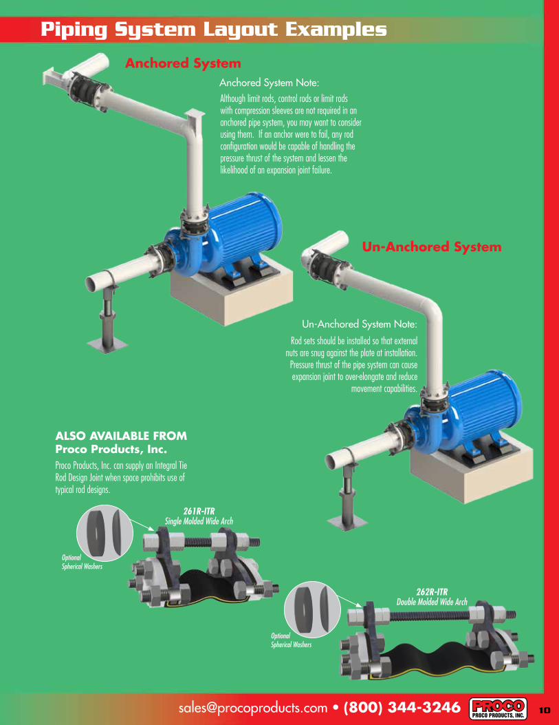
Piping System Layout Examples
Anchored System
Un-Anchored System
Rod sets should be installed so that external nuts are snug against the plate at installation. Pressure thrust of the pipe system can cause expansion joint to over-elongate and reduce
movement capabilities.
Un-Anchored System Note:
ALSO AVAILABLE FROM Proco Products, Inc.Proco Products, Inc. can supply an Integral Tie Rod Design Joint when space prohibits use of typical rod designs.
Optional Spherical Washers
261R-ITR Single Molded Wide Arch
Optional Spherical Washers
262R-ITR Double Molded Wide Arch
Anchored System Note:Although limit rods, control rods or limit rods with compression sleeves are not required in an anchored pipe system, you may want to consider using them. If an anchor were to fail, any rod configuration would be capable of handling the pressure thrust of the system and lessen the likelihood of an expansion joint failure.
2431 North Wigwam Dr. (95205) P.O. Box 590 • Stockton, CA
95201-0590 • USA
Toll-Free Phone: (800) 344-3246
Facsimile: (209) 943-0242
(209) 943-6088
email: [email protected]
website: http://www.procoproducts.com
NATIONWIDE AND CANADA
INTERNATIONAL
R E P R E S E N T E D B Y :
9/14
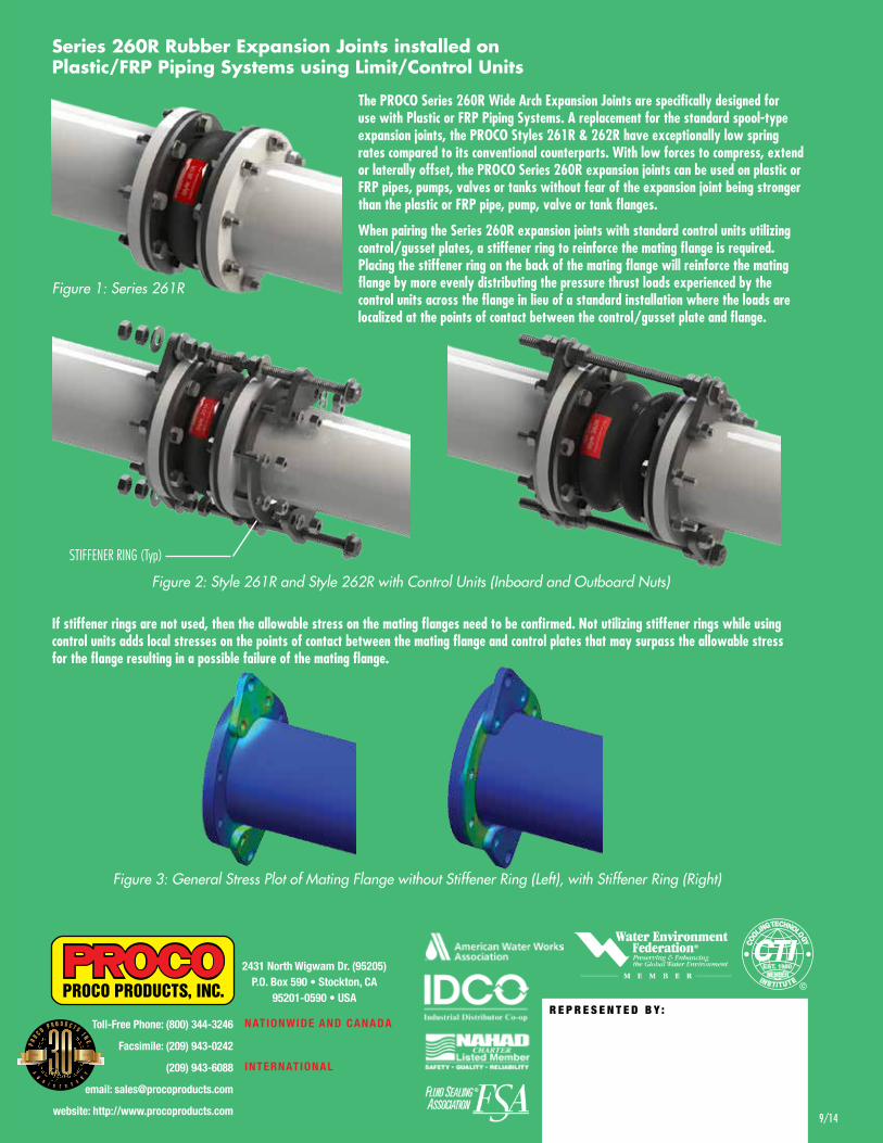
Series 260R Rubber Expansion Joints installed on Plastic/FRP Piping Systems using Limit/Control Units
The PROCO Series 260R Wide Arch Expansion Joints are specifically designed for use with Plastic or FRP Piping Systems. A replacement for the standard spool-type expansion joints, the PROCO Styles 261R & 262R have exceptionally low spring rates compared to its conventional counterparts. With low forces to compress, extend or laterally offset, the PROCO Series 260R expansion joints can be used on plastic or FRP pipes, pumps, valves or tanks without fear of the expansion joint being stronger than the plastic or FRP pipe, pump, valve or tank flanges.
When pairing the Series 260R expansion joints with standard control units utilizing control/gusset plates, a stiffener ring to reinforce the mating flange is required. Placing the stiffener ring on the back of the mating flange will reinforce the mating flange by more evenly distributing the pressure thrust loads experienced by the control units across the flange in lieu of a standard installation where the loads are localized at the points of contact between the control/gusset plate and flange.
If stiffener rings are not used, then the allowable stress on the mating flanges need to be confirmed. Not utilizing stiffener rings while using control units adds local stresses on the points of contact between the mating flange and control plates that may surpass the allowable stress for the flange resulting in a possible failure of the mating flange.
Figure 3: General Stress Plot of Mating Flange without Stiffener Ring (Left), with Stiffener Ring (Right)
Figure 2: Style 261R and Style 262R with Control Units (Inboard and Outboard Nuts)
Figure 1: Series 261R
STIFFENER RING (Typ)