Copyright 2008 Carrier Corporation Form 36CB-1PD Chilled beam units offer: • An increase in total airflow • Sensible cooling and heating options • Induction or convection operation • Adjustable hole lengths and integral manual damper function on active beams Features/Benefits Chilled beam systems are suitable for use in high cooling load applications or where individual temperature control is required. Active and passive chilled beam systems Active (supply air) chilled beams oper- ate with induction, where incoming primary air induces room air through the beam coil. The primary and in- duced room airflow is then discharged through the outlet slot of the beam into the room, resulting in a total airflow of 3 to 4 times greater than the primary airflow. Passive beams work using a reverse chimney effect, where cooler air inside the beam has a higher density than the surrounding room air. The difference in density in combination with the height of the beam induces room air down through the beam coil. 36CBAC,AE,AF,AN, PB,PD,PS Series Active and Passive Chilled Beams 11 to 190 cfm Product Data 36CBAF 36CBAC 36CBAE 36CBPB,PS 36CBAN A36-448.eps A36-449.eps A36-450.eps A36-451.eps A36-453.eps 36CBPD A36-452 [deleted lines].eps
Transcript
Copyright 2008 Carrier Corporation Form 36CB-1PD
Chilled beam units offer:• An increase in total airflow• Sensible cooling and heating
options• Induction or convection operation• Adjustable hole lengths and integral
manual damper function on active beams
Features/BenefitsChilled beam systems are suitable for use in high cooling load applications or where individual temperature control is required. Active and passive chilled beam systemsActive (supply air) chilled beams oper-ate with induction, where incoming primary air induces room air through the beam coil. The primary and in-duced room airflow is then discharged through the outlet slot of the beam into the room, resulting in a total airflow of 3 to 4 times greater than the primary airflow.
Passive beams work using a reverse chimney effect, where cooler air inside the beam has a higher density than the surrounding room air. The difference in density in combination with the height of the beam induces room air down through the beam coil.
36CBAC,AE,AF,AN,PB,PD,PS Series
Active and PassiveChilled Beams
11 to 190 cfm
ProductData
36CBAF
36CBAC
36CBAE
36CBPB,PS
36CBAN
A36-448.eps
A36-449.eps
A36-450.eps
A36-451.eps
A36-453.eps
36CBPD
A36-452[deletedlines].eps
2
Comfort controlAirflow can be adjusted using the com-fort control function featured on all ac-tive chilled beams (option on 36CBAF unit).
Using the patented control rails, air-flow is adjusted by varying the hole lengths in the primary air channel.
Beams have independently adjust-able hole lengths on each side, permit-ting different air distribution patterns (2-way blow, one-way blow, and inter-mediate positions). Simple adjustment of air distribution and capacity makes it possible to adapt to future changes in conditions.
The adjustable hole lengths also mean that the beam has an integral damper function. Moderate changes in the pressure or flow can be made with-out significantly affecting the cooling capacity.
Flow pattern control (FPC)The airflow pattern can be adjusted us-ing the FPC function featured on active chilled beams with comfort control (not available on 36CBAN units).
Built-in vanes and adjustable rails al-low the airflow pattern to be adjusted at different angles: 0, 15, 30, and 45 degrees. Directional adjustments can be achieved in sections of 12 in. within the beam.
Generally, this can reduce air throw by 20%. A beam with FPC can thus be positioned both closer to a wall or to other beams when compared with a beam without FPC.
High airflowAn optional high airflow feature is available on all active chilled beams. To obtain higher airflows, double rows of holes are used on both sides of the ac-tive chilled beam. The double rows of holes give the beam an increased air-flow and cooling capacity or a given pressure drop when compared to beams with a single row of holes.
LightingThe 36CBAF and 36CBPD chilled beams can be supplied with optional direct lighting (not available on size 04 units). The light fitting for a fluorescent lamp is positioned at the center of the chilled beams.
The 36CBAE chilled beam can be supplied with optional indirect lighting (not available on size 04 units). Two lighting fittings for fluorescent lamps are recessed into the upper ”wings” of the beam. The light is directed up-wards, providing indirect and glare-free lighting of the premises.
The capacity of the chilled beams is not affected by the lighting option.
Sprinkler systemSpace for a sprinkler system can be provided as an option in the 36CBAF chilled beam, releasing ceiling space and providing a neater aesthetic ap-pearance with fewer disruptive ele-ments in the ceiling.
Integrating a sprinkler system in the chilled beam is particularly advanta-geous in smaller rooms or offices where the chilled beam is normally po-sitioned in the center of the room be-cause this is also the best position for the sprinkler.
36CB Series chilled beams The 36CBAF active chilled beam is for flush mounting in a standard 24 in. wide false ceiling.
The 36CBAE and 36CBAC active chilled beams are for exposed ceiling applications.
The 36CBAN narrow active chilled beam is for flush mounting in a false ceiling. The 36CBAN is used when limited space is an issue or integrating the beams with other utilities such as lighting.
The 36CBPB wide passive beam and 36CBPS narrow passive chilled beam can be exposed or flush mounted in a false ceiling. The 36CBPD is an exposed passive beam.
Factory-installed optionsComfort control can be used to adjust total airflow byvarying the hole lengths in the primary air channel on the36CBAF unit. Comfort control is a standard feature on36CBAC,AE,AN units.Flow pattern control (FPC) can be used to adjust the airflow pattern on the active chilled beams (not available onthe 36CBAN unit) with comfort control at different angles.High airflow is available on the active chilled beams. Thedouble rows of holes on both sides of the beam increase airflow and cooling capacity or a given pressure drop whencompared to beams with a single row of holes.Heating loops are available on the active chilled beams.The water heating loop gives high heat outputs with nor-mal water supply temperatures.
Integrated lighting is available as a special order on 36CBAE,AF,AN,PD units. Not available on size 04 units. Either high efficiency or high heat output lighting can be selected.
Field-installed accessoriesMounting brackets are available for suspending units inthe ceiling (36CBAC,AE,AF units only).
Suspension brackets are available for suspending unitsin the ceiling (36CBAE,PB,PS units only).Suspension rods are available for all units and have a24 in. extended casing on the connection end.Enclosures with a sealed end wall are available for the36CBAE units.Enclosures without an end wall are available for the36CBAC,AE units. The 36CBAE enclosure can be usedbetween the beam and a wall.End plates are available for the 36CBAE unit enclosureswithout an end wall.A casing adapter is available for use when installing36CBPB,PS units in a series.Protective film is available for use over painted surfaceswhen installing 36CBAC,AE units.A gage rod is available for hole length adjustment forunits with the comfort control function.Flexible water pipes can be used for connecting units tothe water piping system in series applications.
ITEM FACTORY-INSTALLED OPTIONS
FIELD-INSTALLED ACCESSORIES
Comfort Control (36CBAF unit only) XFlow Pattern Control (36CBAC,AE,AF units only) XHigh Airflow (36CBAC,AE,AF,AN units only) XHeating Loop (36CBAC,AE,AF,AN units only) XLighting* (36CBAE,AF,AN,PD units only) XMounting Brackets (36CBAC,AE,AF units only) XSuspension Brackets (36CBAE,PB,PS units only) XSuspension Rods XEnclosure with Sealed End Wall (36CBAE unit only) XEnclosure without End Wall (36CBAC,AE units only) XEnd Plate (36CBAE unit only) XCasing Adapter (36CBPB,PS units only) XProtective Film (36CBAC,AE units only) XGage Rod (36CBAC,AE,AF,AN units only) XFlexible Water Pipes X
4
COMFORT CONTROL
HIGH AIRFLOW
a36-454.eps
A36-455.eps
A36-456.eps
FLOW PATTERN CONTROL
80% 20%
80 % 20 %50% 50%
80% 20 %20% 80%
10 cfm/ft
40 cfm/ft
a36-486
Options and accessories (cont)
5
Systems with chilled beams are suitable for use in highcooling load applications and/or where there is a require-ment for individual temperature control. In offices withnormal room heights, the maximum cooling capacity is 25to 30 Btuh per sq ft of floor area. The limit is set by themaximum permissible velocity in the occupied zone, there-fore high room heights can provide the opportunity forsupplying a greater cooling effect.
Cooling load calculations must take in account the build-ing's dynamic and thermal storage capacity. Simply addingthe "gross loads" together gives an estimate of cooling loadwhich can be approximately 50% too large.
The primary airflow is responsible for the air quality inthe room and while also providing basic cooling. The max-imum recommended difference for the primary air is 18° F.In certain cases, the supply-air temperature can be in-creased by a few degrees with a falling outdoor tempera-ture. The chilled beam covers the rest of the cooling load.The water flow is varied according to the load using a roomsensor.
Compared with a system where the cooling duty is sup-plied entirely by air, a chilled beam system reduces the fanpower requirements and space needed for air-handlingplant equipment and ducting.
Refer to the Application Data book for moreinformation.
Application data
6
To select a 36CB chilled beam, use the product selectionsoftware or contact your Carrier representative. Passivebeams can also be selected by following the example laterin this section.
Taking the room, its loads and the requirement for thechilled beam as its starting point, the selection softwareproposes different beams that are capable of meeting theset requirements. The result is presented in a list of techni-cal data including the cooling capacity, airflow, air pressuredrop, hole length, noise generated, water flow, and waterpressure drop.
The selection software has the ability to draw flow pat-terns for the airflow in the room (in plan view and sections)with one or more chilled beams. The program also takes inaccount that airflow can be different on each side of thebeams, and that the air distribution depends on the FPCsettings. The result for a number of different beams can becompared in a rapid and flexible manner, providing a goodbasis for design decisions.
Input data, codes and technical data can be presented ina printout, as well as a drawing of a section with flow pat-terns. Because the input data documents the conditions inthe form of thermal loads, etc., this printout can be used asa valuable document for the quality assurance of theproject design.
Selection Procedure ExampleI Determine the temperature difference
between air and water.Given:Maximum Beam Length ................................12 ftCooling Capacity .................................2400 BtuhRoom Temperature .......................................75 FChilled Water Temperature ...................57 to 61 F
Temperature difference between air and watert = 75 (57 + 61)/2 = 16 R. See Cooling Effect
in Btuh/ft Effective Length figure on page 37 forresults for a wide passive beam with perforated bot-tom plate and water flow 0.8 gpm: Pk0.8 =220 Btuh/ft.
II Determine the water flow and coolingcapacity.The figure on page 37, Water Flow (GPM) results inwater flow qw = 1.15 gpm for tw = 4 R and cool-ing capacity 2400 Btuh.
III Determine the correction factor for waterflow.Correction for water flow, based on the figure onpage 38, Correction of Cooling Effect for WaterFlow Other than 0.8 GPM, uses the formula K = Pk
1.15/Pk 0.8 = 1.04.The actual effect is therefore 4% higher than theresult given by the diagram, due to the higher waterflow. Pk = 1.04 x 220 = 229 Btuh/ft
IV Select the appropriate unit.The required effective length (coil length) is foundusing: Leff = 2400/229 = 10.5 ftThe casing length is found using: L = 10.5 + 0.4 =10 ft 10 in. It is thus not necessary to use the maxi-mum casing length 12 ft.The figure on page 38, Water Pressure Drop (in.wg) — 36CBPB Unit, gives the pressure drop ofwater across the coil as pw = 3.5 in. wg.
1. The fitting has a T5 fluorescent lamp which is available in two power levels, HE and HO, depending on how muchlight is required. The HE version has an output of 28 W for a 4 ft fitting and 35 W for a 5 ft fitting. The HO versionhas an output of 54 W for a 4 ft fitting and 49 W for a 5 ft fitting.
2. The color temperature of the fluorescent lamp is 830/3000 K.3. The connection cable can be supplied with a plug, Ensto or Wieland connector.
36CBAE UNIT SIZE
ARMATURE LENGTH (ft)
NUMBER OF FITTINGS
OUTPUT (W)HE/HO
06 4 2* 28/5408 5 2* 35/4910 5 2* 35/49
HE — High EfficiencyHO — High Output
A
A
BEAM LENGTH
AA
a36-464.eps
36
CB
AC
,AE S
eries Units
12
36CBAC UNIT COOLING CAPACITY, ONE-WAY BLOW
LEGEND
NOTES:1. Water flow is equal to 0.8 gpm.2. Assume static pressure drop on the air side is 0.25 in. wg.3. T equals the difference between room air temperature and
average water temperature.4. Sound pressure level as measured in a room with 32.8 sq ft room
absorbtion.5. Total cooling capacity of the beam equals the cooling capacity of
the coil plus the cooling capacity of the primary air, where the
cooling capacity of the primary air is based on a difference of14.4 F between the primary air and room temperatures.
6. Data based on tests using the Nordtest method which requires azero temperature difference between the air entering the beam coiland the air at 3.6 ft above the floor surface. To achieve this, thewalls in the test room are cooled. In actual conditions, the temper-ature difference is normally 1.8 to 3.6 F. This is why the tempera-ture difference T should be increased by 1.8 to 3.6 F to avoidoversizing of the beam. Therefore, the table value can beincreased by 10 to 20%.
7. Sound is increased by 2 to 3 dB(A) with top connections.8. The chilled beam can be supplied as a special unit for higher air-
NOTES:1. Water flow is equal to 0.8 gpm.2. Assume static pressure drop on the air side is 0.25 in. wg.3. T equals the difference between room air temperature and
average water temperature.4. Sound pressure level as measured in a room with 32.8 sq ft room
absorbtion.5. Total cooling capacity of the beam equals the cooling capacity of
the coil plus the cooling capacity of the primary air, where thecooling capacity of the primary air is based on a difference of14.4 F between the primary air and room temperatures.
6. Data based on tests using the Nordtest method which requires azero temperature difference between the air entering the beam coiland the air at 3.6 ft above the floor surface. To achieve this, thewalls in the test room are cooled. In actual conditions, the temper-ature difference is normally 1.8 to 3.6 F. This is why the tempera-ture difference T should be increased by 1.8 to 3.6 F to avoidoversizing of the beam. Therefore, the table value can beincreased by 10 to 20%.
7. Sound is increased by 2 to 3 dB(A) with top connections.8. The chilled beam can be supplied as a special unit for higher air-
NOTES:1. Water flow is equal to 0.8 gpm.2. Assume static pressure drop on the air side is 0.25 in. wg.3. T equals the difference between room air temperature and
average water temperature.4. High airflow function data for 36CBAE04 units can be supplied
upon request.
36CBAE UNIT COOLING CAPACITY FACTOR FOR ONE-WAY AND INTERMEDIATE BLOW
NOTE: The value given in the unit cooling capacity table is multiplied bythe capacity factor in the above table to reflect the reduced coil capacityin a one-way blow distribution or intermediate air distribution position.
36CBAE UNIT SIZE AIR DISTRIBUTION MAXIMUM PRIMARY AIRFLOW (cfm) CAPACITY FACTOR
04One-way 5 0.870 to 30% 10 0.9
06One-way 15 0.870 to 30% 15 0.9
08One-way 20 0.870 to 30% 25 0.9
10One-way 25 0.870 to 30% 30 0.9
Performance data (cont)3
6C
BA
C,A
E S
erie
s U
nits
15
36
CB
AC
,AE S
eries Units
0
500
1000
1500
2000
2500
3000
0 10 20 30 40 50
SUPPLY AIR - CFM
BT
UH 6'
8'10'
36CBAC UNIT COOLING CAPACITY — SUPPLY AIR INCLUDED
a36-465.eps
0
500
1000
1500
2000
2500
3000
3500
4000
4500
5000
0 20 40 60 80 100 120
SUPPLY AIR - CFM
BT
UH
4'6'8'10'
36CBAE UNIT COOLING CAPACITY — SUPPLY AIR INCLUDED
a36-466.eps
16
36CBAC UNIT HEATING CAPACITY, ONE-WAY BLOW
LEGEND
NOTES:1. Water flow is equal to 0.8 gpm.2. Assume static pressure drop on the air side is 0.25 in.wg.3. T equals the difference between room air temperature and
average water temperature.4. Heating capacity shown on unit without extended casing.
36CBAE UNIT HEATING CAPACITY, TWO-WAY BLOW
LEGEND
NOTES:1. Water flow is equal to 0.8 gpm.2. Assume static pressure drop on the air side is 0.25 in. wg.3. T equals the difference between room air temperature and
LEGEND NOTE: The sound power levels for each octave band are obtained byadding the sound pressure level dB(A) to the corrections, Koct, given inthe table above. The correction is the average in the area of applicationof the chilled beam.
36CBAC UNIT SOUND ATTENUATION
LEGEND NOTE: The average sound attenuation of chilled beam from duct toroom includes the end reflection of the connecting duct in ceilingmounting.
36CBAE UNIT SOUND POWER LEVEL
LEGEND NOTE: The sound power levels for each octave band are obtained byadding the sound pressure level dB(A) to the corrections, Koct, given inthe table above. The correction is the average in the area of applicationof the chilled beam.
36CBAE UNIT SOUND ATTENUATION
LEGEND NOTE: The average sound attenuation of chilled beam from duct toroom includes the end reflection of the connecting duct in ceilingmounting.
36CBAC UNIT
CORRECTION Koct (dB)
OCTAVE BAND, MEAN FREQUENCY, Hz
63 125 250 500 1000 2000 4000 8000
06 –8 -12 -6 -2 –1 –4 –7 –3
08 –8 -12 -6 -2 –1 –4 –7 –3
10 –8 -12 -6 -2 –1 –4 –7 –3
Tol ± 6 3 2 2 2 2 2 3
Tol ± — Tolerance (dB)
36CBAC UNIT
SOUND ATTENUATION IN PRIMARY AIR DUCT OF THE BEAM (dB)
OCTAVE BAND, MEAN FREQUENCY, Hz
63 125 250 500 1000 2000 4000 8000
06 23 19 10 8 8 13 13 12
08 23 19 10 8 8 13 13 12
10 23 19 10 8 8 13 13 12
Tol ± 6 3 2 2 2 2 2 3
Tol ± — Tolerance (dB)
36CBAE UNIT
CORRECTION Koct (dB)
OCTAVE BAND, MEAN FREQUENCY, Hz
63 125 250 500 1000 2000 4000 8000
04 –4 0 3 3 –2 –4 –11 –18
06 –4 0 3 3 –2 –4 –11 –18
08 –4 0 3 3 –2 –4 –11 –18
10 –4 0 3 3 –2 –4 –11 –18
Tol ± 6 3 2 2 2 2 2 3
Tol ± — Tolerance (dB)
36CBAE UNIT
SOUND ATTENUATION IN PRIMARY AIR DUCT OF THE BEAM (dB)
OCTAVE BAND, MEAN FREQUENCY, Hz
63 125 250 500 1000 2000 4000 8000
04 23 19 10 8 8 13 13 12
06 23 19 10 8 8 13 13 12
08 23 19 10 8 8 13 13 12
10 23 19 10 8 8 13 13 12
Tol ± 6 3 2 2 2 2 2 3
Tol ± — Tolerance (dB)
36
CB
AC
,AE S
eries Units
18
36CBAE LIGHT DISTRIBUTION CURVE
a36-467.eps
LEGEND
NOTE: Light output shown in candle power per 1000 lumens.
NOTES:1. Dimensions shown in inches unless otherwise indicated.2. Water volume cooling = 0.13 gpm.3. Water volume heating = 0.07 gpm.
36CBAF UNIT SIZE L (ft) C (ft) D (ft) E (ft) WEIGHT (lb)
04 4 1 2 – 44
06 6 1 3 – 59
08 8 2 4 – 79
10 10 2 5 – 101
12 12 3 7 3 121
36CBAF UNIT SIZE, EXTENDED CASING L (ft) C (ft) D (ft)
06 8 3 3
08 10 4 4
10 12 4 5
CW — Chilled WaterWW — Warm Water
a36-469.eps
21
Accessory dimensions3
6C
BA
F Series U
nits
36CBAF UNIT DIMENSIONS — LIGHTING OPTION
LEGEND
NOTES:1. The fitting has a T5 fluorescent lamp which is available in two power levels, HE and HO, depending on how
much light is required. The HE version has an output of 28 W for a 4 ft fitting and 35 W for a 5 ft fitting. The HOversion has an output of 54 W for a 4 ft fitting and 49 W for a 5 ft fitting.
2. The color temperature of the fluorescent lamp is 830/3000 K.3. The connection cable can be supplied with a plug, Ensto or Wieland connector.
36CBAF UNIT SIZE
ARMATURE LENGTH (ft)
NUMBER OF FITTINGS
OUTPUT (W)HE/HO
06 4 1 28/5408 5 1 35/4910 4 2 35/4912 4 2 28/54
HE — High EfficiencyHO — High Output
36CBAF06
36CBAF08
36CBAF10
36CBAF12
a36-470.eps
22
Accessory dimensions (cont)3
6C
BA
F S
erie
s U
nits
36CBAF UNIT DIMENSIONS — SPRINKLER OPTION
36CBAF UNIT SIZE A (ft)
06 608 810 1012 12
ø 2.1 in.
ø 2.4 in.
B
A
A/2
B
ø 2.4 in.
ø 2.1 in.SECTION B – B
a36-471.eps
23
36CBAF UNIT COOLING CAPACITY, TWO-WAY BLOW
LEGEND
NOTES:1. Water flow is equal to 0.8 gpm.2. Assume static pressure drop on the air side is 0.25 in. wg.3. T equals the difference between room air temperature and
average water temperature.4. Sound pressure level as measured in a room with 32.8 sq ft room
absorbtion.
5. Total cooling capacity of the beam equals the cooling capacity ofthe coil plus the cooling capacity of the primary air, where the cool-ing capacity of the primary air is based on a difference of 14.4 Fbetween the primary air and room temperatures.
6. Data based on tests using the Nordtest method which requires azero temperature difference between the air entering the beam coiland the air at 3.6 ft above the floor surface. To achieve this, thewalls in the test room are cooled. In actual conditions, the temper-ature difference is normally 1.8 to 3.6 F. This is why the tempera-ture difference T should be increased by 1.8 to 3.6 F to avoidoversizing of the beam. Therefore, the table value can beincreased by 10 to 20%.
7. The chilled beam can be supplied as a special unit for higher air-flow rates than those listed in these tables.
LEGEND NOTES:1. Water flow is equal to 0.8 gpm.2. Assume static pressure drop on the air side is 0.25 in. wg.3. T equals the difference between room air temperature and
average water temperature.
36CBAF UNIT COOLING CAPACITY FACTOR FOR ONE-WAY AND INTERMEDIATE BLOW
NOTE: The value given in the unit cooling capacity table is multiplied bythe capacity factor in the above table to reflect the reduced coil capacityin a one-way blow distribution or intermediate air distribution position.
36CBAF UNIT SIZE AIR DISTRIBUTION MAXIMUM PRIMARY AIR FLOW (cfm) CAPACITY FACTOR
04One-way 11 0.870 to 30% 21 0.9
06One-way 32 0.870 to 30% 42 0.9
08One-way 42 0.870 to 30% 64 0.9
10One-way 64 0.870 to 30% 74 0.9
12One-way 74 0.870 to 30% 95 0.9
Performance data (cont)3
6C
BA
F S
erie
s U
nits
25
36CBAF UNIT HEATING CAPACITY, TWO-WAY BLOW
LEGEND NOTES:1. Water flow is equal to 0.8 gpm.2. Assume static pressure drop on the air side is 0.25 in. wg.3. T equals the difference between room air temperature and aver-
36CBAF UNIT COOLING CAPACITY — SUPPLY AIR INCLUDED
a36-472.eps
26
36CBAF UNIT SOUND POWER LEVEL
LEGEND
NOTE: The sound power levels for each octave band are obtained by addingthe sound pressure level dB(A) to the corrections, Koct, given in the tableabove. The correction is the average in the area of application of the chilledbeam.
36CBAF UNIT SOUND ATTENUATION
LEGEND
NOTE: The average sound attenuation of chilled beam from duct to roomincludes the end reflection of the connecting duct.
36CBAF UNIT
CORRECTION Koct (dB)
OCTAVE BAND, MEAN FREQUENCY, Hz
63 125 250 500 1000 2000 4000 8000
04 –4 0 3 3 –2 –4 –11 –18
06 –4 0 3 3 –2 –4 –11 –18
08 –4 0 3 3 –2 –4 –11 –18
10 –4 0 3 3 –2 –4 –11 –18
12 –4 0 3 3 –2 –4 –11 –18
Tol ± 6 3 2 2 2 2 2 3
Tol ± — Tolerance (dB)
36CBAF UNIT
SOUND ATTENUATION IN PRIMARY AIR DUCTOF THE BEAM (dB)
OCTAVE BAND, MEAN FREQUENCY, Hz
63 125 250 500 1000 2000 4000 8000
04 21 13 7 7 9 11 12 13
06 21 13 7 7 9 11 12 13
08 21 13 7 7 9 11 12 13
10 21 13 7 7 9 11 12 13
12 21 13 7 7 9 11 12 13
Tol ± 6 3 2 2 2 2 2 3
Tol ± — Tolerance (dB)
Performance data (cont)3
6C
BA
F S
erie
s U
nits
36CBAF LIGHT DISTRIBUTION CURVE
a36-473.eps
LEGEND
NOTE: Light output shown in candle power per 1000 lumens.
NOTES:1. Dimensions shown in inches.2. Water volume cooling = 0.13 gpm coil.3. Water volume heating = 0.07 gpm coil.
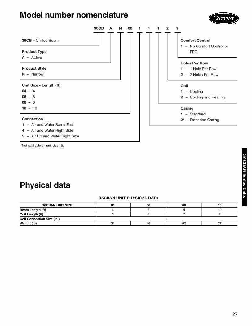
36CBAN UNIT SIZE LENGTH (ft) WEIGHT
(lb)04 4 3106 6 4608 8 6210 10 77
8.78
4.39
5.31
8.27
1.50
3.90
2.95
11.757.28
1.40
1.10
Ø 0.59
5.31
2.13
1.30
4.17 3.94
5.47
8.27
L
Ø 4.92
Ø 0.59
9.76
3.90 4.39
CONNECTION ALTERNATIVE 1 – AIR AND WATER CONNECTIONS RIGHT IN THE DIRECTION OF AIRFLOW
CONNECTION ALTERNATIVE 2 – AIR AND WATER CONNECTIONS THROUGH END WALL
CONNECTION ALTERNATIVE 3 – AIR CONNECTION UP AND WATER CONNECTION RIGHT IN THEDIRECTION OF AIRFLOW
a36-475.eps
29
36CBAN UNIT COOLING CAPACITY, TWO-WAY BLOW
LEGEND
NOTES:1. Water flow is equal to 0.8 gpm.2. Assume static pressure drop on the air side is 0.25 in. wg.3. T equals the difference between room air temperature and
average water temperature.4. Sound pressure level as measured in a room with 32.8 sq ft room
absorbtion.5. Total cooling capacity of the beam equals the cooling capacity of
the coil plus the cooling capacity of the primary air, where the
cooling capacity of the primary air is based on a difference of14.4 F between the primary air and room temperatures.
6. Data based on tests using the Nordtest method which requires azero temperature difference between the air entering the beam coiland the air at 3.6 ft above the floor surface. To achieve this, thewalls in the test room are cooled. In actual conditions, the temper-ature difference is normally 1.8 to 3.6 F. This is why the tempera-ture difference T should be increased by 1.8 to 3.6 F to avoidoversizing of the beam. Therefore, the table value can beincreased by 10 to 20%.
7. Sound is increased by 1 dB(A) with side connections. Sound isdecreased by 1 dB(A) with top connections.
8. The chilled beam can be supplied as a special unit for higher air-flow rates than those listed in these tables.
36CBAN UNIT COOLING CAPACITY FACTOR FOR ONE-WAY AND INTERMEDIATE BLOW
NOTE: The value given in the unit cooling capacity table is multiplied bythe capacity factor in the above table to reflect the reduced coil capacityin a one-way blow distribution or intermediate air distribution position.
36CBAN UNIT SIZE AIR DISTRIBUTION MAXIMUM PRIMARY AIRFLOW (cfm) CAPACITY FACTOR
04One-way 11 0.870 to 30% 21 0.9
06One-way 32 0.870 to 30% 32 0.9
08One-way 42 0.870 to 30% 53 0.9
10One-way 53 0.870 to 30% 64 0.9
Performance data (cont)3
6C
BA
N S
erie
s U
nits
0
500
1000
1500
2000
2500
3000
3500
4000
0 20 40 60 80 100 120
SUPPLY AIR - CFM
BT
UH
4'6'8'10'
36CBAN UNIT COOLING CAPACITY — SUPPLY AIR INCLUDED
a36-476.eps
31
36CBAN UNIT HEATING CAPACITY, TWO-WAY BLOW
LEGEND
NOTES:1. Water flow is equal to 0.8 gpm.2. Assume static pressure drop on the air side is 0.25 in. wg.3. T equals the difference between room air temperature and
LEGEND NOTE: The sound power levels for each octave band are obtained byadding the sound pressure level dB(A) to the corrections, Koct, given inthe table above. The correction is the average in the area of applicationof the chilled beam.
36CBAN UNIT SOUND ATTENUATION
LEGEND NOTE: The average sound attenuation of chilled beam from duct toroom includes the end reflection of the connecting duct.
36CBAN UNIT
CORRECTION Koct (dB)
OCTAVE BAND, MEAN FREQUENCY, Hz
63 125 250 500 1000 2000 4000 8000
04 6 –2 1 1 0 –4 –10 –10
06 6 –2 1 1 0 –4 –10 –10
08 6 –2 1 1 0 –4 –10 –10
10 6 –2 1 1 0 –4 –10 –10
Tol ± 6 3 2 2 2 2 2 3
Tol ± — Tolerance
36CBAN UNIT
SOUND ATTENUATION IN PRIMARY AIR DUCT OF THE BEAM (dB)
NOTES:1. Dimensions shown in inches.2. L = Nominal length 0.31 inches.–
a36-478.eps
35
36
CB
PB
,PD
,PS
Series U
nits
4
4
4
36CBPD UNIT DIMENSIONS — LIGHTING OPTION
LEGEND
NOTES:1. Dimensions shown in feet.2. The fitting has a T5 fluorescent lamp which is available in two power levels, HE and HO, depending on how much
light is required. The HE version has an output of 28 W while the HO version has an output of 54 W.3. The color temperature of the fluorescent lamp is 830/3000 K. 4. The connection cable can be supplied with a plug, Ensto or Wieland connector.
36CBPD UNIT SIZE
FITTING LENGTH (ft)
NUMBER OF FITTINGS
OUTPUT (W)HE/HO
04-08 4 1 28/5410-14 4 2 28/54
HE — High EfficiencyHO — High Output
a36-479.eps
UNIT SIZES 04-08
UNIT SIZES 10-14
36
Performance data3
6C
BP
B,P
D,P
S S
erie
s U
nits
36CBPD LIGHT DISTRIBUTION CURVE
a36-480.eps
LEGEND
NOTE: Light output shown in candle power per 1000 lumens.
36CBPD UNIT SIZE
OUTPUT (W)HE/HO
04-08 28/5410-14 28/54
HE — High EfficiencyHO — High Output
High EfficiencyHigh Output
110°
90°
70°
50°
30°
40°
110°
90°
70°
50°
30°
40°
120° 140° 140° 120°180°
20° 10° 10° 20°0°
500
400
300
200
100
LMS
100
cd/1000 lm
37
36
CB
PB
,PD
,PS
Series U
nits
50
100
150
200
250
300
350
9 10 11 12 13 14 15 16 17 18 19 20 21 22
Δt, R
Pk, Btuh/Ft
36CBPB
36CBDPD,PS
COOLING EFFECT IN BTUH/FT EFFECTIVE LENGTH
NOTES:1. Water flow = 0.8 gpm.2. Data based on tests using the Nordtest method which requires a zero temperature differ-
ence between the air entering the beam coil and the air at 3.6 ft above the floor surface. Toachieve this, the walls in the test room are cooled. In actual conditions, the temperature dif-ference is normally 1.8 to 3.6 F. The temperature difference between room air and watershould in this case be increased by 1.8 to 3.6 F. This is because in the actual conditions, thebeam will produce a higher effect.
a36-481.eps
LEGENDPk — PowerR — Rankines
0
1,000
2,000
3,000
4,000
5,000
0.40 0.60 0.80 1.00 1.20 1.40 1.60 1.80qW, GPM
Pk, Btuh
ΔtW = 7.2°F 6.3°F
5.4°F
4.5°F
3.6°F
2.7°F
1.8°F
WATER FLOW (GPM)
NOTE: Data based on tests using the Nordtest method which requires a zero temperature differencebetween the air entering the beam coil and the air at 3.6 ft above the floor surface. To achieve this, the wallsin the test room are cooled. In actual conditions, the temperature difference is normally 1.8 to 3.6 F. The tem-perature difference between room air and water should in this case be increased by 1.8 to 3.6 F. This isbecause in the actual conditions, the beam will produce a higher effect.
a36-482.eps
LEGENDPk — PowerqW— Flow of Watertw — Temperature Variance
of Supply Water
38
Performance data (cont)3
6C
BP
B,P
D,P
S S
erie
s U
nits
0.7
0.8
0.9
1.0
1.1
0.30 0.80 1.30 1.80 2.30 2.80qW, GPM
CORRECTION
CORRECTION OF COOLING EFFECT FOR WATER FLOWS OTHER THAN 0.8 GPM
a36-483.eps
LEGENDqw — Flow of Water
0
2
4
6
8
10
12
0.4 0.6 0.8 1 1.2 1.4 1.6 1.8
qW, GPM
∆pW, in. wg
12'
4'
6'
14'
10'
8'
WATER PRESSURE DROP (in. wg) — 36CBPB UNIT
a36-484.epsLEGEND
Pw — Water Pressure Dropqw — Flow of Water
39
36
CB
PB
,PD
,PS
Series U
nits
0
2
4
6
8
10
12
0.4 0.6 0.8 1 1.2 1.4 1.6 1.8
qW, GPM
ΔpW, in. wg
12'
4'
6'
14'
10'
8'
WATER PRESSURE DROP (in. wg) — 36CBPD,PS UNITS
a36-485.eps
LEGENDPw — Water Pressure Dropqw — Flow of Water
40
Active Chilled BeamsHVAC Guide SpecificationsSize Range: 4 to 10 ftCarrier Model Number: 36CBAC,AEPart 1 — General1.01 SYSTEM DESCRIPTION
A. Integrated chilled beam system for ventilation, cool-ing, and heating.
B. Equipment shall be completely assembled, andpiped. Capacities and characteristics as listed in theschedule and the guide specifications that follow.
1.02 QUALITY ASSURANCEA. Units shall be tested using the prEN 15116 test
method.B. All units shall be fully quality tested by factory run
testing under normal operating conditions and waterflow rates as described herein.
Part 2 — Product2.01 EQUIPMENT
A. General:1. The chilled beam shall be equipped with adjust-
ing rails, comfort control, and flow patterncontrol.
2. 36CBAC chilled beam unit shall be designed forexposed installation at ceiling level next to parti-tions or walls.
3. 36CBAE chilled beam unit shall be designed forexposed installation.
B. Unit Casing:1. Airflow through the supply air slot is directed
diagonally upwards and can be adjusted byadjusting rails change the length of the holes inthe primary air channel.
2. Hole lengths of standard beams shall be presetat the longest possible position before delivery.If individual factory adjustment of hole lengths isrequested, all beams shall be marked and mustbe identified at delivery and sorted at the build-ing site.
C. The casing shall be made of galvanized steel sheetand aluminum profiles, and shall be powder paintedin white.
D. The gables shall be made of ABS plastic.E. The standard color shall be RAL 9010, which corre-
sponds to NCS 0502-Y, gloss level 30.F. The bottom plates can be pushed aside to allow easy
cleaning and airflow adjustment.G. Extended casing shall be available.H. Coil:
1. The coil shall be made of copper tubes andaluminum fins, coil diameter connection size is1/2 in. OD.
2. The maximum working pressure shall be232 psi.
3. An optional hot water heating loop can beadded to the beam coil.
4. A purging vent shall be included as standard.I. Special Features:
1. An enclosure without end walls shall bemade available.
2. An enclosure with sealed end walls shall bemade available on 36CBAE units.
3. A gage rod for hole length adjustment isavailable.
4. High airflow shall be made available.5. Heating ability shall be made available.6. Lighting is available as a special order for
36CBAE units.7. Suspension rods shall be made available for unit
suspension.8. Suspension brackets shall be made available on
36CBAE units.9. Flexible water pipes (hoses) shall be made
available for series connections.10. Mounting brackets for ceiling suspension are
available.11. Protective film for installation over painted sur-
faces is available.
Guide specifications — 36CBAC,AE series
41
Active Chilled BeamsHVAC Guide SpecificationsSize Range: 4 to 12 ftCarrier Model Number: 36CBAFPart 1 — General1.01 SYSTEM DESCRIPTION
A. Integrated chilled beam system for ventilation, cool-ing, and heating.
B. Equipment shall be completely assembled, andpiped. Capacities and characteristics as listed in theschedule and the guide specifications that follow.
1.02 QUALITY ASSURANCEA. Units shall be tested using the prEN 15116 test
method.B. All units shall be fully quality tested by factory run
testing under normal operating conditions and waterflow rates as described herein.
Part 2 — Product2.01 EQUIPMENT
A. General:1. The chilled beam unit shall be designed for
flushed mounting in a false ceiling and shall besized to match a standard 2 ft false ceiling mod-ule.
B. Unit Casing:1. Airflow through the supply air slot can be
adjusted using the optional comfort controlfunction by adjusting rails which change thelength of the holes in the primary air channel.
2. Hole lengths of standard beams shall be presetat the longest possible position before delivery ifthe comfort control option is requested.
C. The casing shall be made of galvanized steel sheetand aluminum profiles, and shall be powder paintedin white.
D. The standard color shall be RAL 9010, which corre-sponds to NCS 0502-Y, gloss level 30.
E. Coil:1. The coil shall be made of copper tubes and
aluminum fins, coil diameter connection size is1/2 in. OD.
2. The maximum working pressure shall be232 psi.
3. An optional hot water heating loop can beadded to the beam coil.
4. A purging vent shall be made available.F. Special Features:
1. Flow pattern control shall be made available.2. Comfort control shall be made available.3. High airflow shall be made available.4. Lighting is a special order option.5. Provision for a sprinkler system can be
requested.6. Suspension rods shall be made available for unit
suspension.7. A gage rod for hole length adjustment shall be
made available.8. Mounting brackets shall be made available for
unit installation.9. Flexible water pipes (hoses) shall be made
available for series connections.
Guide specifications — 36CBAF series
42
Active Chilled BeamsHVAC Guide SpecificationsSize Range: 4 to 10 ftCarrier Model Number: 36CBANPart 1 — General1.01 SYSTEM DESCRIPTION
A. Integrated chilled beam system for ventilation, cool-ing, and heating.
B. Equipment shall be completely assembled, andpiped. Capacities and characteristics as listed in theschedule and the guide specifications that follow.
1.02 QUALITY ASSURANCEA. Units shall be tested using the prEN 15116 test
method.B. All units shall be fully quality tested by factory run
testing under normal operating conditions and waterflow rates as described herein.
Part 2 — Product2.01 EQUIPMENT
A. General:1. The chilled beam unit shall be designed for
flushed mounting in a false ceiling and shall besized to match a standard 1 ft false ceilingmodule.
2. The chilled beam shall be equipped with adjust-ing rails, comfort control, and flow patterncontrol.
B. Unit Casing:1. Airflow through the supply air slot can be
adjusted by adjusting rails change the length ofthe holes in the primary air channel.
2. Hole lengths of standard beams shall be presetat the longest possible position before delivery.
C. The casing shall be made of galvanized steel sheetand aluminum profiles, and shall be powder paintedin white.
D. The standard color shall be RAL 9010, which corre-sponds to NCS 0502-Y, gloss level 30.
E. The bottom plates can be pushed aside to allow easycleaning and airflow adjustment.
F. Coil:1. The coil shall be made of copper tubes and
aluminum fins, coil diameter connection size is1/2 in. OD.
2. The maximum working pressure shall be232 psi.
3. An optional hot water heating loop can beadded to the beam coil.
4. A purging vent shall be included as standard.G. Special Features:
1. A gage rod for hole length adjustment shall bemade available.
2. High airflow shall be made available.3. Lighting is a special order option.4. Suspension rods shall be made available for unit
suspension.5. Suspension brackets shall be made available.6. Flexible water pipes (hoses) shall be made
available for series connections.
Guide specifications — 36CBAN series
43
Passive Chilled BeamsHVAC Guide SpecificationsSize Range: 4 to 14 ftCarrier Model Number: 36CBPB,PD,PSPart 1 — General1.01 SYSTEM DESCRIPTION
A. Chilled beam system for cooling where air is sup-plied by separate supply air devices.
B. Equipment shall be completely assembled, andpiped. Capacities and characteristics as listed in theschedule and the guide specifications that follow.
1.02 QUALITY ASSURANCEA. Units shall be tested using the EN 14518 test
method.B. All units shall be fully quality tested by factory run
testing under normal operating conditions and waterflow rates as described herein.
Part 2 — Product2.01 EQUIPMENT
A. General:1. 36CBPB,PS chilled beams shall be designed for
either flush installation in a suspended ceiling orexposed installation without a false ceiling. The36CBPD unit is only intended for exposedinstallation.
2. 36CBPD chilled beams shall be designed forexposed installation.
B. Unit Casing:1. For 36CBPB,PS units, a casing adapter with
the same form as the beam shall be madeavailable to adjust the beam length or to be
placed between beams in case of seriesconnection.
2. The adapter shall be open-ended to allow theentry of duct and water pipes. A closed endshall be available upon request.
3. The bottom plate of the adapter shall be remov-able in order to make duct or pipe connections.
C. The casing shall be made of galvanized steel sheetand aluminum profiles, and shall be powder paintedin white.
D. The standard color shall be RAL 9010, which corre-sponds to NCS 0502-Y, gloss level 30. Other colorsshall be made available upon request.
E. Coil:1. The coil shall be made of copper tubes and
aluminum fins, coil diameter connection size is1/2 in. OD.
2. The maximum working pressure shall be232 psi.
3. A purging vent shall be required on the returnpipe if the beam is positioned in a high point inthe piping system.
F. Special Features:1. Lighting is a special order option on 36CBPD
units. Not available on 36CBPB,PS units.2. Suspension rods shall be made available for unit
suspension.3. Suspension brackets shall be made available.4. Beam attachments shall be made available.5. Flexible water pipes (hoses) shall be made
available for series connections.
Guide specifications — 36CBPB,PD,PS series
Manufacturer reserves the right to discontinue, or change at any time, specifications or designs without notice and without incurring obligations.Pg 44 Catalog No. 04-52360001-01 Printed in U.S.A. Form 36CB-1PD
Replaces: NEWSection 8Tab 8c
Carrier Corporation • Syracuse, New York 13221 8-08