39
Product Application Guidelines Weighfeeders
Product Application Guidelines
Weighfeeders

2
Weighfeeder Application Guidelines 2015 Siemens Level and Weighing
Table of Contents Preface ......................................................................................................................................................... 4
Introduction .................................................................................................................................................. 5
Engineering terms: ................................................................................................................................. 6
Weighfeeder Selection .............................................................................................................................. 9
Application and Mounting Guidelines .................................................................................................... 10
Applications ............................................................................................................................................... 11
Silo, Bin and Hopper Applications ..................................................................................................... 11
Screw Conveyor Applications ............................................................................................................. 14
Rotary Feeder Applications ................................................................................................................ 14
Bucket Elevator Applications .............................................................................................................. 16
Belt Conveyor Applications ................................................................................................................. 16
Drag Conveyor Applications ............................................................................................................... 17
Vibratory Feeder Applications ............................................................................................................ 18
Component Considerations .................................................................................................................... 18
Scale ...................................................................................................................................................... 18
Speed Sensor ....................................................................................................................................... 19
Construction .......................................................................................................................................... 19
Inlet ......................................................................................................................................................... 20
Shear gate ............................................................................................................................................. 21
Belting .................................................................................................................................................... 22
Pulleys .................................................................................................................................................... 23
Idlers ....................................................................................................................................................... 24
Bearings ................................................................................................................................................. 24
Motor ...................................................................................................................................................... 25
Gear Reducer ....................................................................................................................................... 27
Belt Tensioner ....................................................................................................................................... 27
Belt Scraper........................................................................................................................................... 28
Belt Plow ................................................................................................................................................ 28
Belt Cleaning Brush ............................................................................................................................. 29
Belt Guide Rollers or Trackers ........................................................................................................... 29

3
Weighfeeder Application Guidelines 2015 Siemens Level and Weighing
Belt Tracking Switches ........................................................................................................................ 29
Plugged Discharge Switch .................................................................................................................. 30
Application Considerations ..................................................................................................................... 30
Belt Speed ............................................................................................................................................. 30
Calibration ............................................................................................................................................. 30
Installation ............................................................................................................................................. 31
Inclines ................................................................................................................................................... 31
Belt loading ............................................................................................................................................ 31
Abrasion ................................................................................................................................................. 31
Temperature .......................................................................................................................................... 31
Fluidization ............................................................................................................................................ 31
Adhesion ................................................................................................................................................ 32
Causticity ............................................................................................................................................... 32
Maintenance and Modifications ............................................................................................................. 32
Maintenance .......................................................................................................................................... 32
Modifications ......................................................................................................................................... 33
Material Build-up ................................................................................................................................... 33
Material Spills ........................................................................................................................................ 33
Material Rating Definitions ...................................................................................................................... 34
Rating Chart for Common Materials ...................................................................................................... 35
Product Selection ..................................................................................................................................... 37
Weighfeeder .......................................................................................................................................... 37
Notes .......................................................................................................................................................... 38
4
Weighfeeder Application Guidelines 2015 Siemens Level and Weighing
Preface
The contents of this guide are intended to be used for pre-sales activities when a weighfeeder solution is being considered. The information required to properly size a weighfeeder does not take into consideration many of the other factors that are part of the environment or the system which can lead to adverse performance if not properly managed or eliminated. Please refer to the appropriate weighfeeder operating instructions for full specifications, as well as installation and calibration procedures. Operating Instructions can be downloaded from the Siemens website at www.siemens.com/weighing When installed and applied according to the guidelines, weighfeeder design and manufacture results in greater accuracy. To help the user maintain the accuracy and performance of the weighfeeder, this guideline provides recommendations for the proper application of weighfeeders under specific material handling and environmental conditions. The application of a weighfeeder is tailored to the individual requirements of each process. Detailed information about the material, the process, the control and the size of the unit are all considered when engineering a weighfeeder. The material characteristics and the way it flows from one process to another is a large factor in the sizing of a weighfeeder. Compared to a belt scale application on an existing conveyor where size and speed of the belt are known, a weighfeeder is an independent machine that interfaces between two connection points to control or monitor the material flow. Every component of a weighfeeder is configured to the specific needs of the application. Belt speeds need to be slow enough to ensure that shearing material from a bin or hopper is consistent and does not damage the belt or create belt slip. Motors are sized to exceed the power demands of starting a static belt under a full belt loading condition. Gearboxes are selected to achieve a specific belt speed to maintain a design rate and transfer high motor RPM to a usable conveyor speed. Weighfeeder belting needs to be configured based on the material abrasiveness and its temperature. The weigh bridge components need to be configured so that load cell capacity and speed sensor inputs are adequate to meet the requirements of the integrator. This is all in addition to normal conveyor design to ensure that the frame and structure is rigid enough to handle the load and dynamic forces from shearing and conveying material. Throughout the configuration process, strict safety standards and components are applied including belt tracking switches or pull cord alarms. Applying these rigorous design standards ensure that weighfeeders are designed specifically for weighing accuracy and feeding consistency. The guide is meant to be read chronologically, to both teach and build on the knowledge of how certain aspects of the application can compound with others to create poor performance from the weighfeeder.
Note: Other weighfeeder solutions are available such as apron feeders, weighscrews, and rotor weighfeeders .
Users of these mechanical based solutions can use this guide in the same way as those with belt conveyor-based designs can. Non-contact technologies also exist such as Microwave, Ultrasonic, Laser, Optical and Gamma ray. These technologies are non-contacting and therefore do not have the same point of reference as a gravimetric-based weighfeeder which is the basis for this application guideline.

5
Weighfeeder Application Guidelines 2015 Siemens Level and Weighing
Introduction Weighfeeders can:
Control flow rate of material into or out of a process
Indicate flow rate of material during processing
Totalize material for inventory monitoring
Quality control for material batching
Production monitoring A weighfeeder is a weighing solution that combines three components:
1. Weighfeeder (with weigh scale and speed sensor) Weighfeeders monitor and control the flow rate of gravity fed material from a pre feed device such as a bin or conveyor
2. Integrator Integrators collect the data from the weighfeeder and output:
Flow rate (max. & min.)
Belt load
Belt speed
Totalization
3. Variable frequency drive/converter (only required for controlling feed rate) Weighfeeders are generally not well suited to flow monitoring of batches or samples less than 10 minutes in duration.
6
Weighfeeder Application Guidelines 2015 Siemens Level and Weighing
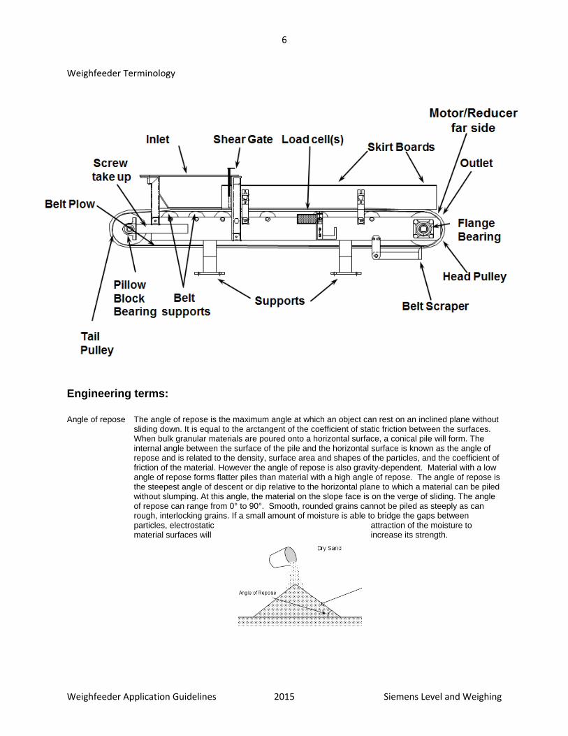
Weighfeeder Terminology
Engineering terms:
Angle of repose The angle of repose is the maximum angle at which an object can rest on an inclined plane without sliding down. It is equal to the arctangent of the coefficient of static friction between the surfaces. When bulk granular materials are poured onto a horizontal surface, a conical pile will form. The internal angle between the surface of the pile and the horizontal surface is known as the angle of repose and is related to the density, surface area and shapes of the particles, and the coefficient of friction of the material. However the angle of repose is also gravity-dependent. Material with a low angle of repose forms flatter piles than material with a high angle of repose. The angle of repose is the steepest angle of descent or dip relative to the horizontal plane to which a material can be piled without slumping. At this angle, the material on the slope face is on the verge of sliding. The angle of repose can range from 0° to 90°. Smooth, rounded grains cannot be piled as steeply as can rough, interlocking grains. If a small amount of moisture is able to bridge the gaps between particles, electrostatic attraction of the moisture to material surfaces will increase its strength.
7
Weighfeeder Application Guidelines 2015 Siemens Level and Weighing
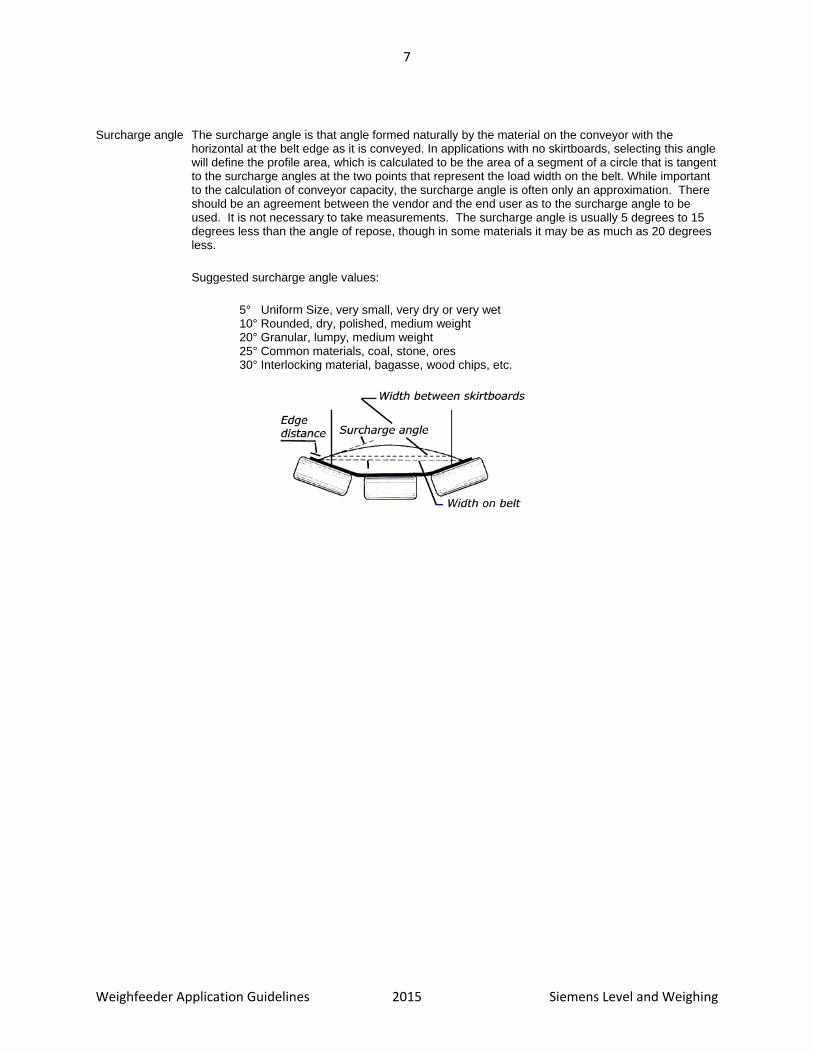
Surcharge angle The surcharge angle is that angle formed naturally by the material on the conveyor with the horizontal at the belt edge as it is conveyed. In applications with no skirtboards, selecting this angle will define the profile area, which is calculated to be the area of a segment of a circle that is tangent to the surcharge angles at the two points that represent the load width on the belt. While important to the calculation of conveyor capacity, the surcharge angle is often only an approximation. There should be an agreement between the vendor and the end user as to the surcharge angle to be used. It is not necessary to take measurements. The surcharge angle is usually 5 degrees to 15 degrees less than the angle of repose, though in some materials it may be as much as 20 degrees less.
Suggested surcharge angle values:
5° Uniform Size, very small, very dry or very wet 10° Rounded, dry, polished, medium weight 20° Granular, lumpy, medium weight 25° Common materials, coal, stone, ores 30° Interlocking material, bagasse, wood chips, etc.

8
Weighfeeder Application Guidelines 2015 Siemens Level and Weighing
Friction factor The material friction factor is used to calculate the required power to move material against a
stationary component. Friction factors affect belt tension and are based on CEMA standards. The following friction factors are available for use:
Material Cs Factor (lbf/(ft-in²)
Cs Factor (kgf/(m-mm²)
Alumina, pulverized, dry 0.121 10.810
Ashes, coal, dry 0.057 5.092
Bauxite, ground 0.188 16.795
Beans, navy, dry 0.080 7.147
Borax 0.073 6.521
Bran, granular 0.024 2.144
Cement, Portland, dry 0.212 18.939
Cement, Clinker 0.123 10.988
Clay, ceramic, dry fines 0.092 8.219
Coal, anthracite, sized 0.054 4.824
Coal, bituminous, mined 0.075 6.700
Coke, ground fine 0.045 4.020
Coke, lumps and fines 0.019 1.697
Copra, lumpy 0.020 1.787
Cullet 0.084 7.504
Flour, wheat 0.027 2.412
Grains, wheat, corn or rye 0.043 3.841
Gravel, bank run 0.115 10.274
Gypsum, 1/2" sceenings 0.090 8.040
Iron ore, 200 lbs/cuft 0.276 24.657
Lime, burned, 1/8" 0.117 10.452
Lime, hydrated 0.049 4.377
Limestone, pulverized, dry 0.128 11.435
Magnesium chloride, dry 0.028 2.501
Oats 0.022 1.965
Phosphate rock, dry, broken 0.018 1.608
Salt, common, dry, fine 0.081 7.236
Sand, dry, bank 0.137 12.239
Sawdust, dry 0.008 0.715
Soda ash, heavy 0.070 6.253
Starch, small lumps 0.062 5.539
Sugar, granulated dry 0.034 3.037
Wood chips, hogged fuel 0.009 0.804
9
Weighfeeder Application Guidelines 2015 Siemens Level and Weighing
Weighfeeder Selection Choose a weighfeeder that best suits your application, based on the following criteria:
Maximum flowrate.
Minimum flowrate.
Particle size.
Maximum material temperature. See page 31 for more information on specifying your weighfeeder using temperature.
Bulk density of material.
Use your application criteria to find an appropriate weighfeeder. Then, confirm your choice by checking the Material Rating Chart starting on page 35, giving secondary consideration to the following application consequences:
Abrasion Abrasion limits the life of the inlet, skirtboards and belt. Also consider wear caused by material clogging from the shear gate and under the skirtboards between the belt supports. See page 31 for more information.
Adhesion Material should not stick and build up on the belt and skirtboards as it will cause a calibration shift because of the continuous presence of non-conveyed material. See page 32for more information.
Causticity Caustic materials can damage weighfeeder components. Be aware of caustic vapours as well. See page 32 for more information.
Material damage from shearing or build up. Some materials must not be damaged by the conveying or weighing process, horseshoe style inlets offer better protection for the material if it is fragile. The use of other options such as corrugated side wall belts with no skirtboards should be avoided if material can pack in the sidewall causing contamination or damage.
Consider if the the following aspects have been properly considered: Idler loading (CEMA class) Effect of load and belt speed on predicted bearing life (L10) Belt tension and wrap Motor power to convey the material and rotate all the idlers or pulleys as well as manage friction Shaft deflection and stress

10
Weighfeeder Application Guidelines 2015 Siemens Level and Weighing
Application and Mounting Guidelines In static testing with test weights or chains, the weighfeeder’s performance is repeatable, linear, and reacts minimally to ambient temperature changes. The weighfeeder is a very accurate machine in static mode. The weighfeeder application will determine how well the weighfeeder performs in dynamic mode with material conveying. Follow the guidelines below to reduce the need for modification after the initial installation of your weighfeeder.
Condition the material flow as required to provide repeatable flow patterns for consistent flow from the pre-feed device. Linearization of repeatable flow patterns can also be achieved through weighfeeder integrator functions.
Ensure that chute-work downstream from the weighfeeder will not cause material back up at the outlet discharge flange.
Avoid materials that flow poorly and/or materials that will stick to surfaces of the weighfeeder.
Protect components of the weighfeeder system from damaging, caustic material. Damage can come from the weighed material, as well as from backup air from the downstream process or air flow from the upstream process.
If the material is abrasive, ensure that the belt, inlet`, and skirtboards are selected for maximum abrasion resistance. AR steel and thicker belt options are ideal for abrasive materials. The transition chutes upstream from the weighfeeders inlet may also require protection.
Ensure that the temperature of the material being weighed falls within the weighfeeder temperature range. The material temperature can have a greater range than the ambient conditions around the weighfeeder. Also ensure that the ambient air temperature is not unreasonably high.
If required, ensure that the weighfeeder has the necessary optional equipment for operation within a hazardous environment.
Isolate or remove any influence from vibration
Plan for a method of referencing a known material sample during verification and final calibration of the weighfeeder. Two methods are: pre-weighing and running the sample through the weighfeeder, or collecting and weighing after the sample has been run through the weighfeeder.
11
Weighfeeder Application Guidelines 2015 Siemens Level and Weighing
Applications
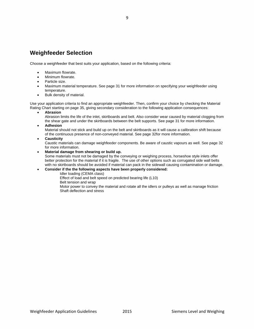
Silo, Bin and Hopper Applications The most typical application for a weighfeeder is shearing material out of a storage vessel such as a silo, bin, or hopper. The material is stored in the bin and replenished as it is discharged through the feeder at specific set points so that the bin never runs empty. Some silos can be over 300 ft (100 m) in height. The deflection of these structures under full load or thermal expansion can be considerable. A material shut off gate is required in order to perform routine maintenance as well as weighfeeder calibration. These gates can either be rod, knife, or slide style.
A rod or pin gate has a series of steel bars sliding inside a rectangular opening. This valve provides full product flow when open, and is ideal for product sizes of 0.5” (12mm) or greater. For applications with a large variance between particle sizes with fine rods that interlock can be used from both sides of the bin discharge for better flow control. A knife gate valve has a semi-circular gate sliding inside a circular body. This valve creates a circular aperture when open while acting as a seal when closed. Knife gate valves are very common in piping systems for fluid flow, but are also used for control of powdered, dry bulk solids. A slide gate valve is the rectangular version of the knife gate valve. It is traditionally used for granular, dry bulk solids and does not use the sealing function that is required for fluids and fine powders. All three devices modulate flow in control systems, and provide on/off control. For modulation applications, the gate and seat should be designed so the opening and closing of the gate maintains a linear opening.
Positioning and Mounting When used with weighfeeders, rod gate, knife gate and slide gate valves are usually positioned at the bottom of bins and silos. The slide gate valve is relatively problem-free because the materials being handled are usually free-flowing and granular. In an on/off situation, all valve types should have the opening size fixed and limited so the flow levels remain consistent. Bin aeration and minimum bin levels should be consistently maintained. If the head of the material in the bin becomes a determining factor of flowrate, a special transition chute between the gate valve and the weighfeeder may be required to eliminate weighfeeder starvation. Any gate or connection to a bin or silo should be done with a flexible coupling to ensure thermal expansion and filling do not transfer additional loads to the weighfeeder.
Flow Considerations Normally, material flow problems only occur when the bin level drops below a certain point, or flow conditions within the bin change suddenly, or if the bin runs empty and the weighfeeder then receives material from the process without it coming to rest within the bin. In applications that are designed to ensure bin emptying for cleaning or
12
Weighfeeder Application Guidelines 2015 Siemens Level and Weighing
material expiration issues, the weighfeeder should include special impact-rated idlers or belt supports in the inlet area to help with material impact from high velocities. The gate can also be closed to allow for material fill in the bin to isolate the weighfeeder from damage or material fluidization. When measuring granular material using a knife gate valve, a decrease in bin level to low levels or an empty bin can also cause problems. Also, when the knife gate valve is used with powders, inconsistent flows from the bin due to the lack of, or the excess of, flow assistance can cause measuring problems. Flow assistance is usually aeration or vibration to assist the material flow from the bin or hopper.
Chute Applications
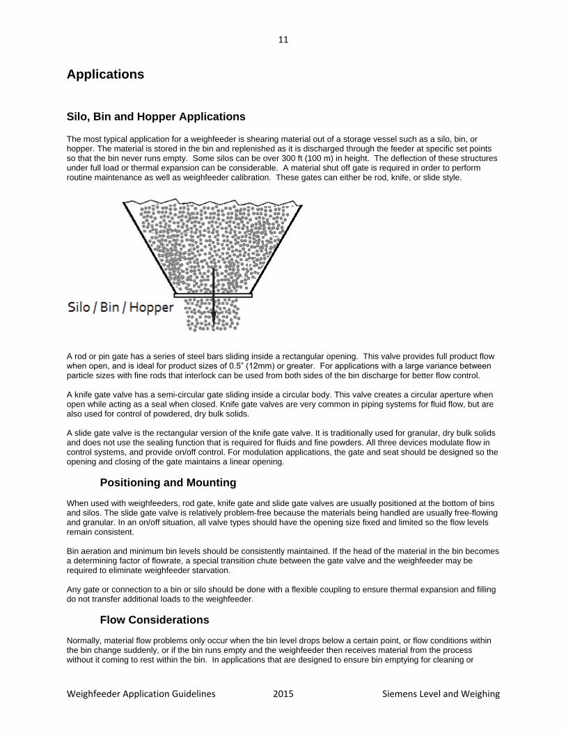
Short Fall Chutes A short fall chute from a prefeeding device or a bin requires minimal monitoring unless the material has exceptionally poor flow characteristics, is abrasive, or the change in level in the bin would cause different discharge velocities.
In general, to ensure a smooth, repeatable flow of material to the inlet, create a straight run of chute work immediately before the inlet that is aligned with the inlet vertically. The material can collect and form a consistent and repeatable flow pattern before entering the inlet. This is especially important when the chute has a second angle.
13
Weighfeeder Application Guidelines 2015 Siemens Level and Weighing
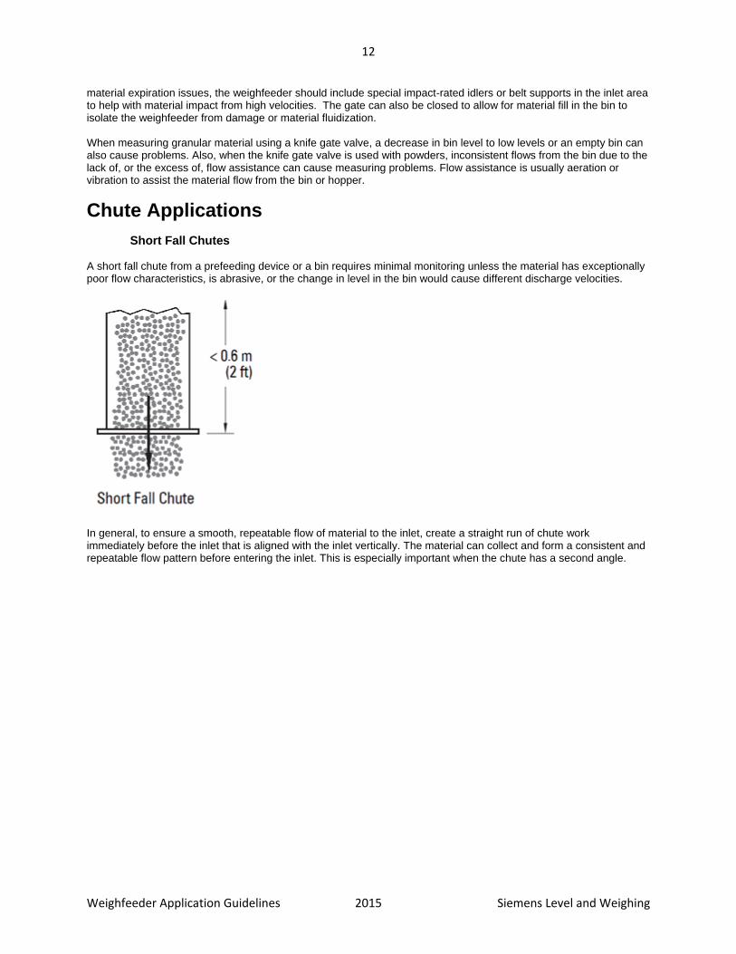
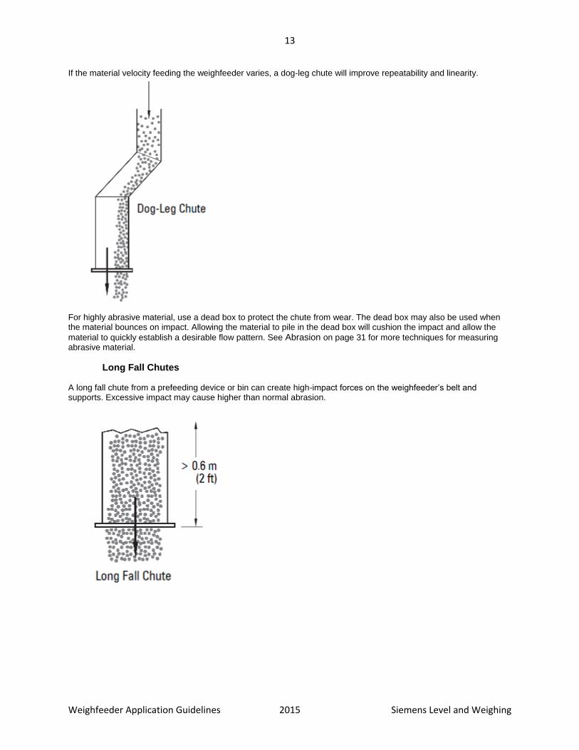
If the material velocity feeding the weighfeeder varies, a dog-leg chute will improve repeatability and linearity.
For highly abrasive material, use a dead box to protect the chute from wear. The dead box may also be used when the material bounces on impact. Allowing the material to pile in the dead box will cushion the impact and allow the
material to quickly establish a desirable flow pattern. See Abrasion on page 31 for more techniques for measuring abrasive material.
Long Fall Chutes A long fall chute from a prefeeding device or bin can create high-impact forces on the weighfeeder’s belt and supports. Excessive impact may cause higher than normal abrasion.

14
Weighfeeder Application Guidelines 2015 Siemens Level and Weighing
Screw Conveyor Applications
Screw conveyors have a ribbon (or flight) of steel formed and fixed to a shaft. Rotation of the shaft within a tubular structure will convey the material horizontally, or on a slope, from an inlet point to a discharge point. These devices tend to have constant speed with low lineal distance per second values. Screw conveyors provide an inexpensive method of transporting and/or controlling the feed rate of many products. Variable speed screw conveyors are often called screw feeders and typically shear material from a bin or hopper.
Screw Conveyor Application Notes When using a high speed conveyor and/or transporting abrasive materials, a dead box arrangement can limit the impact and wear on the inlet. The material flow will need to be tuned to the volumetric capacity of the weighfeeder. The inlet should always have enough material to allow for consistent shearing. If the inlet is overfilled, it could jam or plug and damage the belt or shear gate. If the inlet is underfilled, the material profile won’t be consistent for optimum weighing accuracy.
Flighting Normally, the pulsation frequency of material flow from a screw conveyor with standard flighting is acceptable for weighfeeders. However, short pitch flighting and double flighting are preferred because they generate a higher pulse frequency and lower magnitude of material pulses.
Constant Speed Conveyors Constant speed conveyors can be applied to maximum speeds of 40 rpm. For abrasive materials, a dead box arrangement is suitable for low and high speed applications.
Variable Speed Conveyors Slower conveyors, with a top speed of up to 20 rpm, can be applied as well. For abrasive materials, a dead box arrangement would be suitable for low and high speed applications.
Rotary Feeder Applications Rotary feeders are generally used for modulating (dosing) material flow or for providing an air seal between processes. The rotary feeder is composed of vanes fixed to a shaft that rotates within a cylindrical structure. The inlet and discharge flanges are normally in-line but can be offset.

15
Weighfeeder Application Guidelines 2015 Siemens Level and Weighing
In most cases, rotary feeders are designed with minimal clearance between the vanes and the housing, and can be classified as rotary airlock feeders. A reasonably good air seal can be maintained because of the structure and because a pocket can be sealed from both the inlet and the outlet at any given time. This feature allows the device to be applied to situations where the material to be modulated is aerated and free-flowing, as well as in applications where it is desirable to transfer material from one point to another while maintaining an air seal.
Rotary Feeder Application Notes The pockets normally discharge material as a pulse. Rotary feeders seldom exceed 30 rpm. Worn vanes and housing will contribute to poor modulation control, as well as leakage of both material and air. Rotary feeders often require the vanes and housing to be resurfaced and machined on a regular basis to compensate for this wear. Constant speed rotary feeders are generally driven by an AC voltage gear motor/chain drive arrangement. Variable speed rotary feeders tend to be driven by a motor speed controlled DC gear motor/chain drive arrangement, although an AC gear motor can be used with a variable frequency controller. The material flow will need to be tuned to the volumetric capacity of the weighfeeder. The inlet should always have enough material to allow for consistent shearing. If the inlet is overfilled, it could jam or plug and damage the belt or shear gate. If the inlet is underfilled, the material profile won’t be consistent for optimum weighing accuracy.
Constant Speed Rotary Feeders Weighfeeders can be applied to constant speed rotary feeders, below maximum speeds of 10 rpm. Above that speed, the variation of the trajectory of material from the feeder may cause undesirable wear patterns inside the weighfeeders inlet. For highly abrasive materials, a dead box arrangement would reduce wear to the inlet and belt.
Variable Speed Rotary Feeders Weighfeeders can be applied to variable speed rotary feeders with control being derived from either the flow rate or belt loading output from the weighfeeder. This allows for an automatic tuning of the rotary feeder to ensure a consistent material flow.
Cylindrical Feeders A special version of the rotary air lock feeder has been developed. It uses cylindrical slotting of a solid shaft to create a continuous flow of material through the feeder without creating a pulsating flow. This device is a preferred pre-feeder for weighfeeders because of the smooth material flow and because a consistent pressure seal can be maintained.

16
Weighfeeder Application Guidelines 2015 Siemens Level and Weighing
Bucket Elevator Applications Bucket elevators are conveying devices that elevate material vertically from a lower level to a higher level. Buckets are attached to a chain drive or a reinforced belt. A chain drive is generally slow and material pulsates heavily. A reinforced belt design, sometimes called a leg, is generally used in the grain industry. This belt travels very quickly and creates a high frequency of pulsation. Bucket elevators are constant speed devices that produce constant discharge velocities. Flow pulsation on slower moving elevators will require mechanical damping. Higher speed elevators cause more material abrasion due to higher discharge velocities.
Bucket Elevator Application Notes When using a bucket elevator, a dead box arrangement can limit the impact and wear on the inlet. The material flow will need to be tuned to the volumetric capacity of the weighfeeder. The inlet should always have enough material to allow for consistent shearing. If the inlet is overfilled, it could jam or plug and damage the belt or shear gate. If the inlet is underfilled, the material profile won’t be consistent for optimum weighing accuracy.
Low Speed Bucket Elevator Knife or rod gate valves can be used effectively to dampen flow pulses. The valve should be mounted at an opening that will provide the most effective damping without causing material plugging and/or backup.
High Speed Bucket Elevator For high discharge velocities, a dead box arrangement can help limit the velocity and reduce wear when required, if the material is abrasive. The use of the gate valve is not required with a high speed bucket elevator.
Belt Conveyor Applications Belt conveyors convey dry bulk solids in a horizontal or near-horizontal direction. The belt conveyor has a long moving belt travelling over idlers (rollers). The idlers can be flat (one single horizontal roller) or troughed (combination of three rollers installed at various angles to the horizontal). Belt speeds vary
17
Weighfeeder Application Guidelines 2015 Siemens Level and Weighing
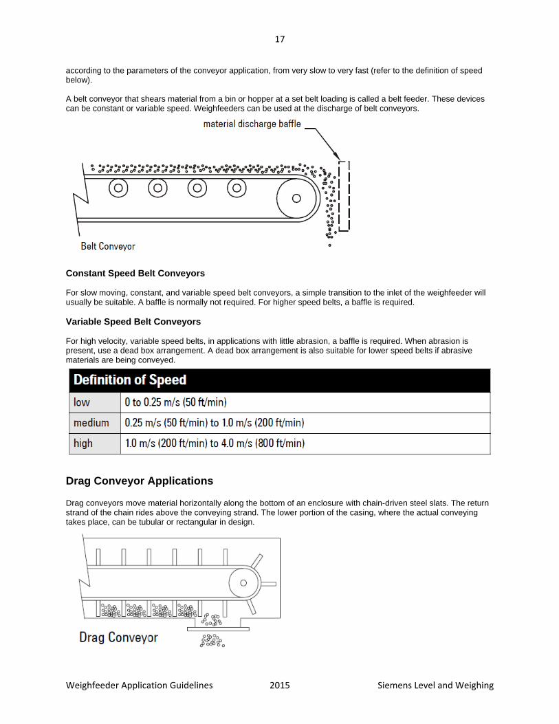
according to the parameters of the conveyor application, from very slow to very fast (refer to the definition of speed below). A belt conveyor that shears material from a bin or hopper at a set belt loading is called a belt feeder. These devices can be constant or variable speed. Weighfeeders can be used at the discharge of belt conveyors.
Constant Speed Belt Conveyors For slow moving, constant, and variable speed belt conveyors, a simple transition to the inlet of the weighfeeder will usually be suitable. A baffle is normally not required. For higher speed belts, a baffle is required.
Variable Speed Belt Conveyors For high velocity, variable speed belts, in applications with little abrasion, a baffle is required. When abrasion is present, use a dead box arrangement. A dead box arrangement is also suitable for lower speed belts if abrasive materials are being conveyed.
Drag Conveyor Applications Drag conveyors move material horizontally along the bottom of an enclosure with chain-driven steel slats. The return strand of the chain rides above the conveying strand. The lower portion of the casing, where the actual conveying takes place, can be tubular or rectangular in design.

18
Weighfeeder Application Guidelines 2015 Siemens Level and Weighing
Drag Conveyor Application Notes Drag conveyors move at a slow, constant speed. These conveyors are wide and have large discharge flanges. Material usually discharges in surges, requiring extensive damping. When using a drag conveyor, a dead box arrangement can limit the impact and wear on the inlet. The material flow will need to be tuned to the volumetric capacity of the weighfeeder. The inlet should always have enough material to allow for consistent shearing. If the inlet is overfilled, it could jam or plug and damage the belt or shear gate. If the inlet is underfilled, the material profile won’t be consistent for optimum weighing accuracy.
Vibratory Feeder Applications The vibratory (or pan) feeder is suitable for use with weighfeeders. The material is vibrated down a slightly sloped trough, or pan, by a mechanical oscillating drive, making the material flow even and consistent. The feeders can feed at a constant vibration rate, which can be varied by modulating the amplitude of the vibrations to create a variable vibration rate.
When using a vibration feeder, ensure the vibrations are isolated from the weighfeeder.
Component Considerations
Scale The belt scale within the weighfeeder requires all the attention to detail that a normal belt scale application requires, however the weighfeeder is designed to be an optimum weighing device with the scale integrated into it. Mounting load cells outside of the weighfeeder frame allows for quick and easy cleaning as well as calibration. Vertical adjustment of the scale allows for easy alignment with the approach and retreat belt supports.

19
Weighfeeder Application Guidelines 2015 Siemens Level and Weighing
Recommendation Follow all the belt scale guidelines where applicable for use on a weighfeeder. Select load cell capacity based on the belt loading and electronic limitations of the signal processing. Typically any load cell signal below 2mV is not acceptable. The capacity of the load cell should not be exceeded.
Speed Sensor The speed sensor is normally mounted to the driven pulley of the weighfeeder. Return belt mounted versions can also be used, however positive contact and installation space may be a concern. Motor-mounted speed sensors are also an option, however belt-slip from the drive pulley is not detected with a motor mounted version. An ideal combination is a driven pulley primary speed sensor with a secondary motor mounted sensor to detect belt slip as well as accurately monitor the belt speed.
Recommendation Select a driven pulley mounted speed sensor with the proper resolution based on the belt speed and electronic limitations of the signal processing. Typically anything under 2Hz will not be a reliable signal for accurate weighing. 2000 Hz output is acceptable as a maximum limit, however the electronics being paired with the weighfeeder will be the definitive limitation. When selecting a speed sensor, choose the lowest resolution that will work in the application at the maximum and minimum flow rates required.
Construction The material of construction for the weighfeeder should meet the demands of the environment it is being placed in. Indoor ambient applications are well suited to mild steel painted versions, where outdoor or wash-down applications should be of a stainless steel construction. The end-user will typically request an open or enclosed style design based on their application history and the regulations for their plant and local government. Where no indication is given on any of these options, best practises should be followed. Open style units are better suited to wash down in
critical applications in the food and chemical process industries. Enclosed versions help control dust and environmental contamination.

20
Weighfeeder Application Guidelines 2015 Siemens Level and Weighing
Recommendation Select the material and type of construction based on end user input and application conditions.
Inlet The inlet of the weighfeeder needs to be designed to promote the “mass flow” of material from the bin or hopper. “Mass flow” helps discharge the bin uniformly so that material does not remain in the bin and become compacted, solidified, or expired. The contrast is “funnel flow” where material will support itself and rat holes or bridging can occur. If the material bridges in the bin and flow is stopped at the weighfeeder, additional material may be supplied to the bin and create an unstable disruption to the normal flow characteristics. This break down or avalanche of material can damage the bin or weighfeeder. A bridge of material is created when an opening occurs at the discharge of the bin, but does not open all the way to the top of the material pile. A rat hole is a column of flow inside the material which leaves material in the bin along the inside edges. “Mass flow” bin designs promote FIFO (first in, first out) and are required for materials where aging or spoiling is a concern. In applications with an inconsistent material feed to the inlet, the horseshoe style inlet can be used. This inlet has no shear gate, so the material profile will not be consistent. In applications with materials that cannot be damaged by shearing, the horseshoe inlet must be used. The inlet should also be designed for compatibility with the material. Caustic materials should be met with stainless steel or coated inlets. In applications with abrasive materials, an inlet constructed of AR400 or AR500 steel or with wear plates should be used. The inlet should have flexible seals that contact the belt to ensure material does not escape from the sides or back. The inlet width should allow for minor belt mis-alignment without colliding with a belt flange as well as cleaning with a belt scraper. In general, inlet width should meet the following standards: Inlet width Belt width Flat belt “B” section/flange belt Corrugated belt 12” / 300mm BW–2” / 50mm BW-4” / 100mm BW-6” / 150mm 18” / 450mm BW-6” / 150mm BW-6” / 150mm BW-10” / 250mm 24” / 600mm BW-6” / 150mm BW-6” / 150mm BW-10” / 250mm 30” / 800mm BW-6” / 150mm BW-6” / 150mm BW-10” / 250mm 36” / 900mm BW-6” / 150mm BW-6” / 150mm BW-10” / 250mm 42” / 1000mm BW-6” / 150mm BW-6” / 150mm BW-10” / 250mm 48” / 1200mm BW-6” / 150mm BW-6” / 150mm BW-10” / 250mm 54” / 1400mm BW-6” / 150mm BW-6” / 150mm BW-10” / 250mm 60” / 1500mm BW-6” / 150mm BW-6” / 150mm BW-10” / 250mm
21
Weighfeeder Application Guidelines 2015 Siemens Level and Weighing
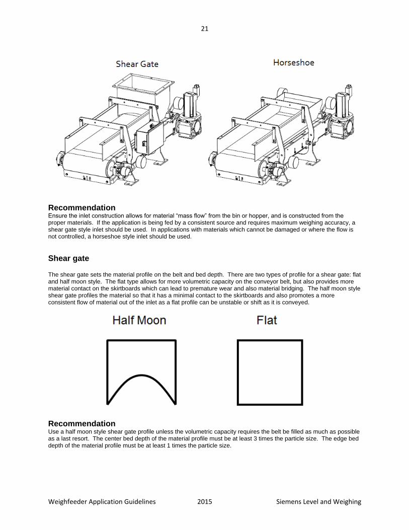
Recommendation Ensure the inlet construction allows for material “mass flow” from the bin or hopper, and is constructed from the proper materials. If the application is being fed by a consistent source and requires maximum weighing accuracy, a shear gate style inlet should be used. In applications with materials which cannot be damaged or where the flow is not controlled, a horseshoe style inlet should be used.
Shear gate The shear gate sets the material profile on the belt and bed depth. There are two types of profile for a shear gate: flat and half moon style. The flat type allows for more volumetric capacity on the conveyor belt, but also provides more material contact on the skirtboards which can lead to premature wear and also material bridging. The half moon style shear gate profiles the material so that it has a minimal contact to the skirtboards and also promotes a more consistent flow of material out of the inlet as a flat profile can be unstable or shift as it is conveyed.
Recommendation Use a half moon style shear gate profile unless the volumetric capacity requires the belt be filled as much as possible as a last resort. The center bed depth of the material profile must be at least 3 times the particle size. The edge bed depth of the material profile must be at least 1 times the particle size.

22
Weighfeeder Application Guidelines 2015 Siemens Level and Weighing
Skirtboards The material containment along the belt is critical to ensure accurate weighing. The skirtboards should be flared out and up from the inlet so that material plugging or jamming does not occur. In applications with materials that can fluidize, skirtboard seals should be added so that spills are avoided at the sides of the belt. The skirtboards should also be designed for compatibility with the material. Caustic materials should be met with stainless steel or coated skirtboards. In applications with abrasive materials skirtboards constructed of AR400 or AR500 steel or with wear plates should be used.
Recommendation The edge bed depth must not exceed the skirtboard height. Select the material of construction based on end user input and application conditions.
Belting In general, weighfeeder belts should be the endless type for optimum weighing accuracy. An endless belt has a more consistent cross section over its entire length, where belts with a mechanical splice have a singular heavy section which can impact accuracy. An endless style belt requires a cantilevered weighfeeder frame for belt removal. Cantilevered frames and endless belts also provide a faster changeover than vulcanizing in place or mechanical splice belts. Belt PIW rating must be determined by the application considerations such as material bed depth, belt width, conveyor, and inlet length. The PIW rating must be met or exceeded to ensure reliable conveying of the material. The belt PIW rating should not exceed 400, as the belt becomes self-supporting at that tension rating and will not provide proper deflection for accurate weighing results. Weighfeeder belts are normally supported on flat pans, bars, or idlers so that tension and temperature influences are minimized. Heat dissipation through a belt to electronic components is considered good but the temperature specifications of the belt and of the weighfeeder should not be exceeded. Where possible, actual temperature profiling can provide data for comparison with a high degree of reliability. Applications conveying minerals or aggregate are suited towards an SBR (Styrene-butadiene) style belt. Higher temperature applications can use Butyl styles. For applications in food and chemical industries, a polyurethane type belt can be generally used. Higher temperature applications can use nitrile or silicone. FDA, USDA and EN 10204 requirements should be reviewed to ensure material contact with the belt is appropriate. These applications typically require an anti-static rated belt as well to control discharges in potentially dangerous areas. Special consideration should be given to applications with a high oil content in the material, as oils can penetrate fabric-based belts. Sharp or abrasive materials which require food or chemical grade belting should use a thicker style Nitrile belt. The thinner polyurethane or silicone style belts will rip or tear easier than a thicker rubber style. If the application has a high water content which should be removed from the material or is subject to CIP (clean in place), the use of an intralox style belt can be used. Intralox style belting features plastic hinged plates with slots to
23
Weighfeeder Application Guidelines 2015 Siemens Level and Weighing
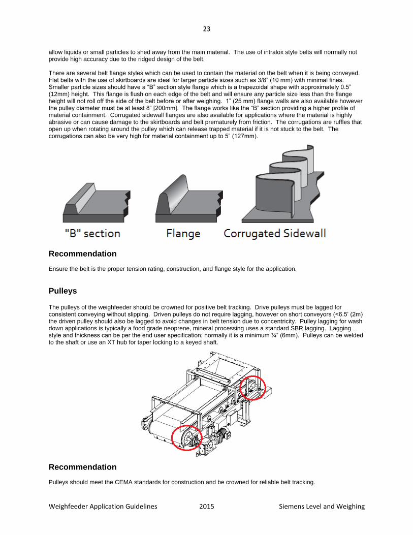
allow liquids or small particles to shed away from the main material. The use of intralox style belts will normally not provide high accuracy due to the ridged design of the belt. There are several belt flange styles which can be used to contain the material on the belt when it is being conveyed. Flat belts with the use of skirtboards are ideal for larger particle sizes such as 3/8” (10 mm) with minimal fines. Smaller particle sizes should have a “B” section style flange which is a trapezoidal shape with approximately 0.5” (12mm) height. This flange is flush on each edge of the belt and will ensure any particle size less than the flange height will not roll off the side of the belt before or after weighing. 1” (25 mm) flange walls are also available however the pulley diameter must be at least 8” [200mm]. The flange works like the “B” section providing a higher profile of material containment. Corrugated sidewall flanges are also available for applications where the material is highly abrasive or can cause damage to the skirtboards and belt prematurely from friction. The corrugations are ruffles that open up when rotating around the pulley which can release trapped material if it is not stuck to the belt. The corrugations can also be very high for material containment up to 5” (127mm).
Recommendation Ensure the belt is the proper tension rating, construction, and flange style for the application.
Pulleys The pulleys of the weighfeeder should be crowned for positive belt tracking. Drive pulleys must be lagged for consistent conveying without slipping. Driven pulleys do not require lagging, however on short conveyors (<6.5’ (2m) the driven pulley should also be lagged to avoid changes in belt tension due to concentricity. Pulley lagging for wash down applications is typically a food grade neoprene, mineral processing uses a standard SBR lagging. Lagging style and thickness can be per the end user specification; normally it is a minimum ¼” (6mm). Pulleys can be welded to the shaft or use an XT hub for taper locking to a keyed shaft.
Recommendation Pulleys should meet the CEMA standards for construction and be crowned for reliable belt tracking.
24
Weighfeeder Application Guidelines 2015 Siemens Level and Weighing
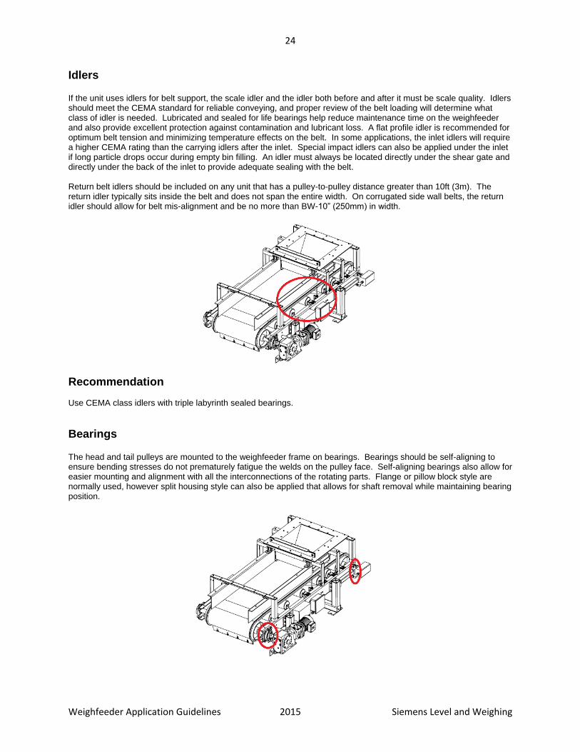
Idlers If the unit uses idlers for belt support, the scale idler and the idler both before and after it must be scale quality. Idlers should meet the CEMA standard for reliable conveying, and proper review of the belt loading will determine what class of idler is needed. Lubricated and sealed for life bearings help reduce maintenance time on the weighfeeder and also provide excellent protection against contamination and lubricant loss. A flat profile idler is recommended for optimum belt tension and minimizing temperature effects on the belt. In some applications, the inlet idlers will require a higher CEMA rating than the carrying idlers after the inlet. Special impact idlers can also be applied under the inlet if long particle drops occur during empty bin filling. An idler must always be located directly under the shear gate and directly under the back of the inlet to provide adequate sealing with the belt. Return belt idlers should be included on any unit that has a pulley-to-pulley distance greater than 10ft (3m). The return idler typically sits inside the belt and does not span the entire width. On corrugated side wall belts, the return idler should allow for belt mis-alignment and be no more than BW-10” (250mm) in width.
Recommendation Use CEMA class idlers with triple labyrinth sealed bearings.
Bearings The head and tail pulleys are mounted to the weighfeeder frame on bearings. Bearings should be self-aligning to ensure bending stresses do not prematurely fatigue the welds on the pulley face. Self-aligning bearings also allow for easier mounting and alignment with all the interconnections of the rotating parts. Flange or pillow block style are normally used, however split housing style can also be applied that allows for shaft removal while maintaining bearing position.
25
Weighfeeder Application Guidelines 2015 Siemens Level and Weighing
Recommendation Bearings must meet or exceed the loading required for the weighfeeder. Wash down applications will generally require a composite or stainless steel housing.
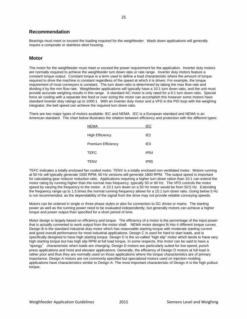
Motor The motor for the weighfeeder must meet or exceed the power requirement for the application. Inverter duty motors are normally required to achieve the weighfeeder turn down ratio or rate range. Inverter duty motors feature a constant torque output. Constant torque is a term used to define a load characteristic where the amount of torque required to drive the machine is constant regardless of the speed at which it is driven. For example, the torque requirement of most conveyors is constant. The turn down ratio is determined by taking the max flow rate and dividing it by the min flow rate. Weighfeeder applications will typically have a 10:1 turn down ratio, and the unit must provide accurate weighing results in this range. A standard AC motor is only rated for a 6:1 turn down ratio. Special force air cooling with a separate line feed or over sizing the motor can accomplish this however some motors have standard inverter duty ratings up to 1000:1. With an inverter duty motor and a VFD in the PID loop with the weighing integrator, the belt speed can achieve the required turn down ratio. There are two major types of motors available: IEC and NEMA. IEC is a European standard and NEMA is an American standard. The chart below illustrates the relation between efficiency and protection with the different types:
NEMA IEC
High Efficiency IE2
Premium Efficiency IE3
TEFC IP54
TENV IP55
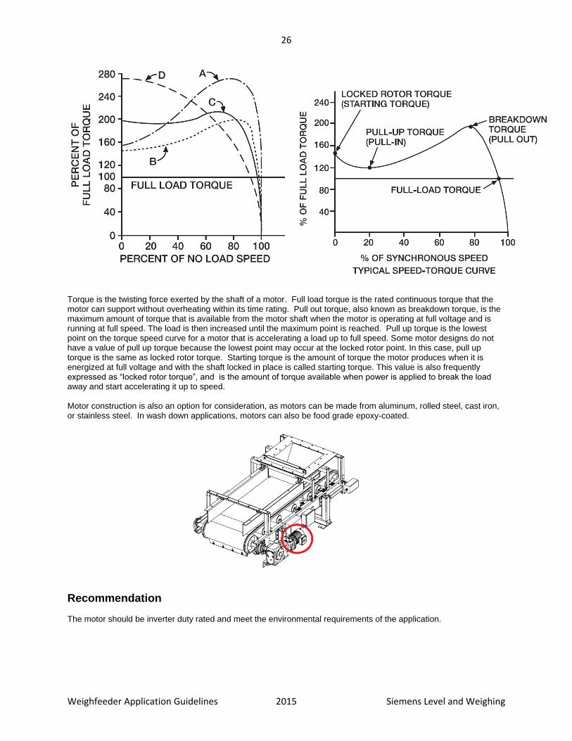
TEFC indicates a totally enclosed fan cooled motor; TENV is a totally enclosed non ventilated motor. Motors running at 50 Hz will typically generate 1500 RPM; 60 Hz versions will generate 1800 RPM. The output speed is important for calculating gear reducer reduction ratio. Applications requiring a higher turn down ration than 10:1 can extend the motor rating by running higher than the normal max frequency, typically 50 or 60 Hz. The VFD controls the motor speed by varying the frequency to the motor. A 10:1 turn down on a 50 Hz motor would be from 50:5 Hz. Extending the frequency range up to 1.5 times the normal running frequency allows for a 15:1 turn down ratio. Going below 5 Hz is not recommended, as the dependability of the signal from the drive may not provide reliable conveying speeds. Motors can be ordered in single or three phase styles or also for connection to DC drives or mains. The starting power as well as the running power need to be evaluated independently, but generally motors can achieve a higher torque and power output than specified for a short period of time. Motor design is largely based on efficiency and torque. The efficiency of a motor is the percentage of the input power that is actually converted to work output from the motor shaft. NEMA motor designs fit into 4 different torque curves. Design B is the standard industrial duty motor which has reasonable starting torque with moderate starting current and good overall performance for most industrial applications. Design C is used for hard to start loads, and is specifically designed to have high starting torque. Design D is the so-called “high slip” motor which tends to have very high starting torque but has high slip RPM at full load torque. In some respects, this motor can be said to have a
“spongy” characteristic when loads are changing. Design D motors are particularly suited for low speed, punch
press applications and hoist and elevator applications. Generally, the efficiency of Design D motors at full load is rather poor and thus they are normally used on those applications where the torque characteristics are of primary importance. Design A motors are not commonly specified but specialized motors used on injection molding applications have characteristics similar to Design A. The most important characteristic of Design A is the high pullout torque.
26
Weighfeeder Application Guidelines 2015 Siemens Level and Weighing
Torque is the twisting force exerted by the shaft of a motor. Full load torque is the rated continuous torque that the motor can support without overheating within its time rating. Pull out torque, also known as breakdown torque, is the maximum amount of torque that is available from the motor shaft when the motor is operating at full voltage and is running at full speed. The load is then increased until the maximum point is reached. Pull up torque is the lowest point on the torque speed curve for a motor that is accelerating a load up to full speed. Some motor designs do not have a value of pull up torque because the lowest point may occur at the locked rotor point. In this case, pull up torque is the same as locked rotor torque. Starting torque is the amount of torque the motor produces when it is energized at full voltage and with the shaft locked in place is called starting torque. This value is also frequently expressed as “locked rotor torque”, and is the amount of torque available when power is applied to break the load away and start accelerating it up to speed. Motor construction is also an option for consideration, as motors can be made from aluminum, rolled steel, cast iron, or stainless steel. In wash down applications, motors can also be food grade epoxy-coated.
Recommendation The motor should be inverter duty rated and meet the environmental requirements of the application.

27
Weighfeeder Application Guidelines 2015 Siemens Level and Weighing
Gear Reducer The motor for the weighfeeder is running at a very high speed, 1500-1800 RPM, so a gear reducer converts that speed to a suitable belt travel speed for accurate weighing and conveying. The gear reducer sizing is dependent on many application details such as belt width, material profile, conveyor length, material bulk density, and infeed length, as well as motor power, shaft size, bearing size, and environmental conditions. The torque required by the application must be met with a minimum of a 1.2 safety factor. This allows for some jamming to occur without damaging the gear reducer. A hollow bore shaft mount style is the most popular option as it can be easily replaced and maintained compared to a belt or chain drive style system. The helical bevel style gear reducer provides optimum torque ratings as well as compact mounting and versatile installation options. The input of the gear reducer must match the flange type of the motor. The orientation of mounting has an impact on the quantity of oil that is to be used. The application will provide a precise reduction ratio required; the next highest value provided by the gear reducer manufacturer is sufficient for selection. Gear reducer construction is limited, however in wash down applications they can be food grade epoxy coated. Food grade oil can also be supplied when required.
Recommendation The gear reducer should have a 1.2 service factor compared to the application demands.
Belt Tensioner The belt tension must remain constant during operation. For critical or high accuracy applications, a gravity actuated belt tensioner allows for changes in tension due to temperature influences or material flow changes. The driven pulley bearings are normally mounted on some kind of telescoper or threaded bearing slider to properly track and tighten the belt.

28
Weighfeeder Application Guidelines 2015 Siemens Level and Weighing
Recommendation Use gravity based belt tensioners on high accuracy or critical applications.
Belt Scraper Keeping the belt clean during operation is critical for weighing applications as material can build up and continuously be weighed without discharging into the process, creating a performance offset. The belt scraper cleans the material contact side of the belt at the discharge end. The scraper blade should be positioned so that material that is cleaned off the belt enters into the process. The scraper blade can contact the belt from tension of a spring or counterweight. The blade length needs to provide adequate cleaning, while also allowing for minor belt tracking movements and not colliding with belt flanges.
Recommendation A belt scraper should always be included on the weighfeeder to help clean the belt during operation.
Belt Plow Keeping the belt clean during operation is critical for reliable conveying, as material can build up on the pulleys and create a change in tension, which will lead to belt mis-alignment. The belt plow is mounted against the clean side of the belt as close to the tail pulley as possible to ensure adequate cleaning. The plow blade is a chevron shape and centered on the belt to ensure proper cleaning. The blades must protrude past the edges of the belt so that material is pushed off the underside of the belt.
Recommendation A belt plow should always be included on the weighfeeder to help clean the belt during operation.
29
Weighfeeder Application Guidelines 2015 Siemens Level and Weighing
Belt Cleaning Brush Keeping the belt clean during operation is critical for weighing applications, as material can build up and continuously be weighed without discharging into the process, this creates a performance offset. The belt cleaning brush cleans the material contact side of the belt at the inlet end. The brush should be positioned so that the brush is against the bottom edge of the belt plow. The brush length needs to provide adequate cleaning while also allowing for minor belt tracking movements.
Recommendation A belt cleaning brush should be included on the weighfeeder in extremely dusty applications or with adhesive materials.
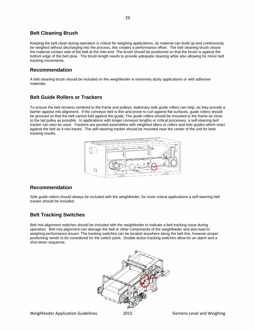
Belt Guide Rollers or Trackers To ensure the belt remains centered to the frame and pulleys, stationary side guide rollers can help, as they provide a barrier against mis-alignment. If the conveyor belt is thin and prone to curl against flat surfaces, guide rollers should be grooved so that the belt cannot fold against the guide. The guide rollers should be mounted to the frame as close to the tail pulley as possible. In applications with longer conveyor lengths or critical processes, a self-steering belt tracker can also be used. Trackers are pivoted assemblies with weighted idlers or rollers and side guides which react against the belt as it mis-tracks. The self-steering tracker should be mounted near the center of the unit for best tracking results.
Recommendation Side guide rollers should always be included with the weighfeeder, for more critical applications a self-steering belt tracker should be included.
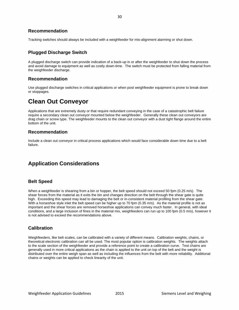
Belt Tracking Switches Belt mis-alignment swtiches should be included with the weighfeeder to indicate a belt tracking issue during operation. Belt mis-alignment can damage the belt or other components of the weighfeeder and also lead to weighing performance issues. The tracking switches can be located anywhere along the belt line, however proper positioning needs to be considered for the switch point. Double action tracking switches allow for an alarm and a shut-down sequence.
30
Weighfeeder Application Guidelines 2015 Siemens Level and Weighing
Recommendation Tracking switches should always be included with a weighfeeder for mis-alignment alarming or shut down.
Plugged Discharge Switch A plugged discharge switch can provide indication of a back-up in or after the weighfeeder to shut down the process and avoid damage to equipment as well as costly down-time. The switch must be protected from falling material from the weighfeeder discharge.
Recommendation Use plugged discharge switches in critical applications or when post weighfeeder equipment is prone to break down or stoppages.
Clean Out Conveyor Applications that are extremely dusty or that require redundant conveying in the case of a catastrophic belt failure require a secondary clean out conveyor mounted below the weighfeeder. Generally these clean out conveyors are drag chain or screw type. The weighfeeder mounts to the clean out conveyor with a dust tight flange around the entire bottom of the unit.
Recommendation Include a clean out conveyor in critical process applications which would face considerable down time due to a belt failure.
Application Considerations
Belt Speed When a weighfeeder is shearing from a bin or hopper, the belt speed should not exceed 50 fpm (0.25 m/s). The shear forces from the material as it exits the bin and changes direction on the belt through the shear gate is quite high. Exceeding this speed may lead to damaging the belt or in-consistent material profiling from the shear gate. With a horseshoe style inlet the belt speed can be higher up to 70 fpm (0.35 m/s). As the material profile is not as important and the shear forces are removed horseshoe applications can convey much faster. In general, with ideal conditions, and a large inclusion of fines in the material mix, weighfeeders can run up to 100 fpm (0.5 m/s), however it is not advised to exceed the recommendations above.
Calibration Weighfeeders, like belt scales, can be calibrated with a variety of different means. Calibration weights, chains, or theoretical electronic calibration can all be used. The most popular option is calibration weights. The weights attach to the scale section of the weighfeeder and provide a reference point to create a calibration curve. Test chains are generally used in more critical applications as the chain is applied to the unit on top of the belt and the weight is distributed over the entire weigh span as well as including the influences from the belt with more reliability. Additional chains or weights can be applied to check linearity of the unit.
31
Weighfeeder Application Guidelines 2015 Siemens Level and Weighing
Installation The process connection points of a weighfeeder are the inlet and discharge. On open style units there is no discharge connection point and horseshoe style inlets are also isolated from the pre feed process. When these connection points exist it is important to note that they will not support loads beyond the material flowing through them. The weighfeeder must be installed on a sturdy platform or support structure to ensure that twisting or bending does not occur during or after installation. The weighfeeder requires clearance on the belt change side for replacing and cleaning the belt. Access is also required on the opposite side for calibration and cleaning.
Inclines Weighfeeders are generally installed horizontally. An inclined unit can accurately weigh and control material, however the maximum angle is 10°. Variable inclines are not recommended due to fluctuating material movement during conveying.
Belt loading Belt loading must be reviewed to ensure that the idler class as well as frame and scale are properly sized or engineered. Typically a weighfeeder will not have a belt loading above 500 lb/ft (744 kg/m). If the loading is above this value, a belt feeder with a scale should be considered rather than a weighfeeder. The spacing of the idlers under the inlet and after the inlet also are affected by the belt loading. Idlers should be spaced evenly under the inlet and also before and after the scale idler.
Abrasion Measuring abrasive products reduces the life of the belt and material contact parts. When material changes direction (in the inlet), wear is also a concern. With some highly abrasive materials, protection against inlet and skirtboard wear may also be necessary. AR rated steel can be used for constructing the inlet and skirtboards without the use of a liner. Additional removable liners made out of UHMW PE or AR steel can be used. With highly abrasive materials, it is recommended to not use skirtboards and provide a corrugated sidewall belt.
Temperature The material on a weighfeeder is isolated from any electronic component which allows for a higher material temperature than ambient conditions. Without special features, a typical weighfeeder can convey materials up to 100°C [212°F], higher temperatures are possible up to 200°C (400°F).
Note: The ambient air temperature surrounding the weighfeeder should not exceed 55°C (131°F) in any application.
Fluidization When a dry powdered solid is aerated or accelerates to a critical velocity, it can transform its dynamic state and behave similar to a liquid. In applications with a material that can fluidize, special consideration needs to be paid to the weighfeeder. A rotary airlock is an ideal pre-feed device, as it limits the amount of material that can enter the weighfeeder, and also changes its velocity as it moves through the rotary vanes. A plastic shear curtain should be used behind the shear gate to control dust and particle movement. Skirtboard seals should be used to ensure material does not flush out the sides of the belt and skirtboard covers so that the material does not rush over top of the skirtboards.

32
Weighfeeder Application Guidelines 2015 Siemens Level and Weighing
Adhesion Adhesive materials that build up on the belt, inlet and skirtboards are a concern when the buildup hampers the movement of the material. If the material sticks to the belt, it can be continuously weighed without discharging creating an inaccuracy. It is vital that material not stick and build up on the weigh area of the weighfeeder. Material build up will cause a calibration shift due to the disruption of the material flow, or due to the additional buildup of material over the dynamic scale parts. Material build up in the inlet can also cause damage to the belt as it moves below the material. Most materials will be self-cleaning on the inlet surfaces and on the skirtboards due to the continuous motion of the flow. Some materials will not be self-cleaning and will require anti-stick coatings in the inlet and on the skirtboards. However, some materials simply will not be suitable for weighing with a weighfeeder, especially if the moisture
content is too high. See the Material Rating Chart on page 35 for information. Polishing of the inlet and skirtboards can help as the surface of the steel becomes more smooth and less likely to trap material against it. The flaring effect of the skirtboards also helps promote good material flow to the discharge. Normal bead blasting or paint finishing is not recommended for highly adhesive materials. Adhesion problems are almost always associated with very fine materials such as flour, starch, and icing sugar which have high moisture content. Materials which are larger than powder size tend to be self-cleaning in the area of material movement. In most cases, PTFE coating of the material contact surfaces will be useful for an adhesive material, but if the particle size is fine enough to lodge itself in a microscopic pore on the surface of the PTFE, material build up can still be a problem. In this case, a mirror finish polish may be the best solution and is the less costly resolution. So generally, for an adhesive product, PTFE coating is the first solution unless there is prior knowledge of it not being effective with the material in question. Plasmadized coatings can also be applied. Plasmadizing is the combination of tungsten carbide and PTFE, which provides good protection from abrasion, while also promoting a slick surface that will limit material buildup.
Causticity Materials that have caustic qualities can damage weighfeeder components. Sometimes the material being measured is not caustic itself, but caustic vapors may be present from the processes downstream or upstream from the weighfeeder. Steel components can be made of stainless steel when the device is to be used with caustic materials. The load cell, the most critical component, is fabricated from stainless steel. The load cell’s encapsulated strain gauges are protected by a gel compound. Some caustic materials can damage the load cell potting gel and eventually the strain gauges, especially where the material has a high moisture content. When there is concern about the suitability of a caustic material, use a hermetically sealed IP68+ load cell. The speed sensor can also be constructed from stainless steel or plated aluminum. In applications for caustic material, the belt of the weighfeeder may require special consideration to prevent chemical reaction between the measured material and the belt. Epoxy paint and synergistic coatings may be required as protection of the gear reducer and motor. The weighfeeders inlet and skirtboards may require special painting or stainless steel construction. The standard type 304 stainless steel should be suitable for most caustic material, but some will require type 316, which has a slightly better overall chemical resistance.
Maintenance and Modifications
Maintenance Once the weighfeeder is installed with a pre-feed device, it requires more attention as it is now part of the weighing system. To ensure accurate weighing, take good care of the weighfeeder and the surrounding area. Perform the following maintenance for proper weighfeeder operation:
consistent material flow
lubrication of all bearings
proper belt tracking and training
proper belt cleaning and scraping

33
Weighfeeder Application Guidelines 2015 Siemens Level and Weighing
proper belt take-up operation
proper material and spillage control
Maintenance Precautions:
When welding near the scale, do not allow current to pass through the weighfeeder scale.
Reset the shipping stops to reduce physical shock to the load cells during maintenance.
Modifications Any changes to the process and/or related equipment could have a profound effect upon the operation and resulting accuracy of the weighfeeder.
Recommendation Consult your Siemens representative for advice regarding weighfeeder installation in a modified process system.
Material Build-up Keep the conveyor belt and associated equipment as clean as possible, so that the scale measures only the loads intended and not the added load due to material sticking to the belt. To remove materials that stick to the belt and conveyor equipment, use good quality belt cleaning equipment such as belt scrapers, brushes, and plows. Although scales can be frequently and automatically recalibrated at no load (zero), it is not a good practice to allow material buildup to remain on the belt.
Material Spills General good housekeeping is always important. Material spillage results in lost production and can also adversely affect weighfeeder operation when spilled material wedges between dynamic parts preventing proper scale deflection. In addition, the build-up affects the zero balance of the scale.
Recommendation Do not overload the weighfeeder. As a precaution, install by-pass systems to keep spills from reaching the weighfeeder.

34
Weighfeeder Application Guidelines 2015 Siemens Level and Weighing
Material Rating Definitions
On page 35, materials that have been successfully weighed with a weighfeeder are listed using the rating criteria defined below. Flowability: How the material flows
Poor Material has qualities that cause sluggish and unpredictable flow, including moisture, material size, and particle size.
Fair Material will flow in a repeatable manner, but the application may require adjustment to achieve consistent and repeatable material flow. Having the right infeed configuration and perhaps a polished finish becomes important.
Good Material flows in a predictable and repeatable manner Excellent Material will flow in a predictable and repeatable manner, and will not require flow
aid devices such as bin aeration and bin vibrators.
Abrasion: How easily does the material wear the inlet and skirtboards? Low Very little abrasion, standard painted steel will be sufficient. Medium Material is somewhat abrasive. The inlet and skirtboards should be constructed
from AR400 abrasion resistant steel. High Material is abrasive. The skirtboards should not be included with the weighfeeder
and the inlet should be constructed of AR400 steel.
Adhesion: How easily does the material stick to the inlet, skirtboards or belt? Low Material will not stick to the flow surface of the inlet and skirtboards or belt. Medium Material may build up heavily on the belt where it is not in contact with a cleaning
component. Consider a polished finish for the inlet and skirtboards. High Material will build up in the inlet, skirtboards, and belt. An anti-stick coating is
required for the surfaces of the inlet and skirtboards. A belt cleaning brush should be used.
Causticity: What is the level of chemical reaction that is detrimental to components
of the weighing process? Low Very limited chemical reaction. Standard equipment will be suitable. Medium Material is mildly caustic; paints and coatings offering protection
for the standard components should be considered. High Material is highly caustic, special painting, special coatings
and/or stainless steel options are a requirement.
General Rating: With all things considered, a rating of the material in terms of its suitability for the application of a weighfeeder. Good The material is suitable. Fair The material is suitable, but only if the limiting properties listed above have been
properly addressed. Poor The material, despite attempts to compensate for the limiting properties, will still
not produce results within the specifications of the weighfeeder. The customer should be pre-warned of this possibility.

35
Weighfeeder Application Guidelines 2015 Siemens Level and Weighing
Rating Chart for Common Materials
Material Flowability Abrasion Adhesion Causticity General Rating Alumina good low to high low low good Ammonium Nitrate fair low high high fair Asbestos Fibre fair low low low good Asbestos Rock good medium low low good Ash fair medium medium low fair Barite good low low low good Barley excellent medium low low good Barley Malt good low low low good Beans good medium low low good Bentonite good low low low good Bran good low low low good Calcined Coke good low low low good Calcined Gypsum good low low low good Carbide good medium low high good Carbon good low low low good Carbon Black good low low low good Cattle Feed Pellets good low low low good Cement good low low low good Cheese fair low high low fair Clay fair low high low fair Clinker good high low low fair Coal good medium medium low fair Cocoa fair low medium low fair Cocoa Beans good low low low good Coffee Beans good low low low good Coke good low low low good Copper Calcine good low low low good Copper Concentrate good low low low good Corn excellent medium low low good Corn Fibre good low low low good Corn Flakes fair low low low good Cut Peanuts good low low low good Dog Food (pellets) good low low low good Dog Food (mix) good low low low good Dry Soap poor low high low fair Fertilizer good low medium medium good Flour (Wheat) fair low medium low good Flue Dust good low low low good Flyash good high low low good Fruits good low low low good Garlic good low low low good Gluten fair low medium low good Grain Screenings fair low low low good Grain Tailings fair low low low good Graphite good low low low good Ground Soybean Hulls good low low low good Gypsum fair low low low good Iron Oxide good low low low good Kiln Dust good low low low good Kiln Feed (cement) good low low low good Laundry Detergent poor low high low fair Lime (powder) good low low low good Limestone (crushed) good medium low medium good Malt good low low low good Milk powder good low medium low good Nuts good low low low good Oat Flour good low low low good Oat Groats good low low low good Pasta good low low low good Perlite good low low low good Perlite Ore good high low low fair Petroleum Coke good low low low good Phosphate Rock good low low medium good

36
Weighfeeder Application Guidelines 2015 Siemens Level and Weighing
Material Flowability Abrasion Adhesion Causticity General Rating Plastic Pellets good low low low good Polymer Percol good low low low good Polyethylene Pellets good low low low good Polyethylene Regrind fair low low low good Polystyrene Pellets good low low low good Polymers good low low low good Popping Corn good low low low good Potash good low low medium good Potato Flakes fair low low low good Potato Starch fair low low low good Poultry Feed (mash) good low low low good Pozzolan good low low low good Precipitator Dust good low low low good Puffed Wheat good low low low good Pulverized Coal good low low low good Resin good low low low good Rice good low low low good Rice Hulls fair low low low good Rye Flour good low low low good Salt good low low medium good Salt Cake poor low medium high fair Sand good medium low low good Sawdust fair low low low good Seeds good medium low low good Shale fair low medium low fair Shorts (wheat) good low low low good Silica Flour good low to med low low good Soap Powder fair low high low fair Soda Ash good low medium medium good Sodium Chloride good low low medium good Sodium Sulphate good low low medium fair Soya Beans good medium low low good Soya Bean Hulls fair low low low good Starch fair low medium low fair Steel Shot good medium low low good Sugar good low medium low good Sunflower Seeds good low low low good Tablets good low low medium good Titanium Dioxide good low low low good Tobacco fair low low low fair Unshelled Peanuts good low low low good Uranium Dioxide good low low low good Uranium Trioxide good low low low good Urea fair low high high fair Vegetables good low low low good Vermiculite good low low low good Wheat good medium low low good Wheat Fines good low low low good Whole Onions good low low low good Wood Pellets good low low low good Wood Pulp poor low low low fair Zinc Oxide good low low low good

37
Weighfeeder Application Guidelines 2015 Siemens Level and Weighing
Product Selection
Weighfeeder There are many different styles of weighfeeders available: low capacity, open, enclosed, and high capacity. Generally there are three drivers to selection of the proper weighfeeder:
Application needs Drives the specific selection of models and options. The environment will also play a part: the weighfeeder should be stainless in corrosive areas or near sea ports. If the location is considered hazardous, approved electrical components will be needed
Price point Influences the selection of the type of weighfeeder. Open style models by their nature are less expensive, but if the application is not suited to them, they should not be used.
Weighfeeder sizing Limitations based on application needs and product features or performance will narrow the selection of the product in most cases. Product size, sensor optimization, and material flow means are all considered when a weighfeeder is engineered.

38
Weighfeeder Application Guidelines 2015 Siemens Level and Weighing
Notes

For more information www.siemens.com/weighing


