40
UniGear 550 Medium voltage, arc-proof, air-insulated, metal-clad switchgear Product brochure

UniGear 550Medium voltage, arc-proof, air-insulated,metal-clad switchgear
Product brochure

2
Contents
Description04 Applications
Air-insulated05 Normal service conditions
05 Standards
05 Electrical characteristics
Metal-clad06 Compartments
06 Main busbars
06 Branch connections
06 Earthing switch
06 Earthing busbar
06 Insulating bushings and shutters
06 Cables
06 Gas exhaust duct
Safety07 Interlocks
07 Padlocks
07 Locking magnets
Type tests08 Temperature rise
08 Dielectric
08 Apparatus making and breaking capacity
08 Earthing switch capacity
08 Mechanical operations
Arc proof09 Vacuum circuit-breakers-Vmax
09 Insulating monobloc
Vacuum circuit-breakers11 Vacuum circuit-breakers-Vmax
11 Insulating monobloc
11 Operating mechanism
11 Truck
11 Apparatus-operator interface
12 Standards
Uses and features13 Block-type CTs
13 Bushing-type current transformers
13 Earthing switch ST1-UG
Feeder protection14 General
14 Applications and features
15 Recommended products
Transformer protection16 General
16 Applications and features
Motor protection17 General
17 Applications and features
18 Recommended products
Communication19 General
19 Utility applications IEC 61850
19 SPA
19 LON
19 IEC 60870-5-103
19 DNP V3.0
Industrial applications20 Profibus DP V1
20 Modbus
20 OPC
Arc protection
21 General
21 Applications and features
21 Recommended products
22 Selection guide
REF542plus multifunction protection and control unit23 Hardware
23 Machine-user interface
23 Central unit
24 Communication
24 Synchronization
25 Automatic transfer systems
Typical units and technical data26 Single-line diagram of the typical units
27 Single-line diagram of the busbar applications
27 Graphical symbols
27 Technical data
Main connection example29 Incoming/outgoing-bottom cables
31 Incoming/outgoing-top cables entry (depth: 1650 mm)
33 Incoming/outgoing-top busbar entry (depth: 1650 mm)
35 Bus-tie
36 Measurement
37 Measurement (VTs)
39 Bus-riser
Contens I UniGear 550

3UniGear 550 I Description
Description
The UniGear 550 can be positioned against the wall. This
in turn allows all service and maintenance operations to be
carried out directly from the front.
Accessing the cable area is particularly convenient by simply
removing the base of the circuit-breaker compartment.
As a standard solution, it is possible to connect up to three
singlepole cables per phase (with a maximum cross-section
of 185 mm2 per panel up to 1250 A and 500 mm2 per panel
up to 2000 A) or two cables per phase with a maximum cross
section of 300 mm2 per panel up to 1250 A and 800 mm2 per
panel up to 2000 A).
The connection height of the cables in relation to the floor
should be 600 mm for the panel up to 1250 A and 565 mm
for the 1600 A and 2000 A panels.
As standard solution UniGear 550 uses toroidal current
transformers (CTs) which are fixed onto a “CT Rod". As an
optional solution, the transformers can be fixed on a DIN rail.
The panel design is such that fixed voltage transformers (VTs)
can be inserted into the front of the panel. The capacitive
signal for indicating the voltage present is connected directly
to the insulators which support the busbars on the cable side.
The surge arresters can also be inserted in the cable area.
The UniGear 550 switchgear is fitted with the interlocks and
accessories needed to guarantee top level safety and
reliability, both for the installation and the operators.
It has undergone all the tests required by the international
standards (IEC) and local standards (for example the GB,
Chinese and Russian GOST standards).
The UniGear 550 switchgear panel is the latest product to join
the large family of UniGear products. UniGear 550 mirrors all
the construction characteristics of other UniGear standard
panels.
UniGear 550 can support a maximum panel current of 2000 A and
it is designed to accommodate ABB Vmax/L circuit breaker.
One of the most unique aspects of this panel is its size. It only
measures 550 mm in width, making it a very compact and
versatile product.
It has been built so that it can be connected directly to the
UniGear standard panel. In fact, it has the same overall
dimensions (height and depth) and the same omnibus
busbars, allowing it to handle a maximum current value of up
to 4000 A.

4
Description
ApplicationsBusiness services, public and civil buildings■ Shopping malls
■ Supermarkets
■ Telecom building
■ 0ffice buildings
■ Banks
■ Hospitals
■ Sports grounds
■ Playgrounds
■ Residential areas
■ Large infrastructures and civil works
Light industrial applications■ Machinery
■ Automotive products manufacturing
■ Electronics
■ Communications products processing
■ Tobacco
■ Wine processing
■ Food processing
■ Textile
■ Chemicals
■ Pulp and paper
■ Cement
Transport■ Airports
■ Ports
Power systems■ Switching stations
Description I UniGear 550

5
Normal service conditionsThe rated characteristics of the switchboard are guaranteed
under the following ambient conditions:
■ Minimum ambient temperature:-5℃■ Maximum ambient temperature: +40℃■ Maximum relative humidity: 95%
■ Maximum altitude: 1000 m a.s.1
■ Presence of normal, non-corrosive and uncontaminated
atmosphere
StandardsThe switchboard and main apparatus contained in it comply
Air-insulated
with the following standards:
■ IEC 62271-1 for general purposes
■ IEC 62271-200 for the switchgear
■ IEC 62271-102 for the earthing switch
■ IEC 60071-2 For the insulation coordination
■ IEC 62271-100 for the circuit-breakers
UnlGear 550 has been certified as having satisfied the
requirements of major shipping registers (LR RINA BV and GL)
for use in marine Installations.
In accordance with the IEC 62271-200 standard, UniGear 550
is defined as follows:
■ Partition metallic (PM): This means the panel is equipped
with metallic shutters and partitions between the operating
parts and an open compartment
■ Loss of service continuity (LSC2B): In other words, service
of the main busbar and of the cable compartment is
guaranteed when normal maintenance is being carried
out in one of the main circuit compartments (e.g. circuit-
breaker compartment)
■ Internal arc classified (IAC AFLR): Panels classified as IAC
AFLR, have fulfilled the five criteria of the internal arc tests
from the front, side and rear having fulfilling the five criteria
of the internal arc tests
Degrees of protectionThe degrees of protection of the switchgears conform with
IEC 60529 standards.
UniGear switchboards are normally supplied with the following
standard degrees of protection:
■ IP 4X on the external housing
■ IP 2X inside the units
Color at the external surfaces: RAL 7035
Electrical characteristics
IEC GB GB IEC
Rated voltage kV 12 12 12 17.5
Rated insulationvoltage kV 12 12 12 17.5
Rated power frequency withstand voltage kV 1 m 28 42 42 38
Rated lightning impulse withstand voltage kV 75 75 75 95
Nominal frequency Hz 50-60 50-60 50-60 50-60
Rated short-time withstand current kA 3 s ...31.5 ...31.5 ...31.5(2) ...31.5
Peak curent kA 80 80 80 ...80
Internal arc withstand current kA 1 s ...31.5 ...31.5 ...31.5 ...31.5
Main busbars rated current(1) A ...4000 ...4000 ...4000 ...4000
Branch connections rated current A 630-1250 630-1250 1600-2000 630-1250
(1) Up to 4000 A if coupled with other Unigear units
(2) Panel for 1600 A-2000 A is tested for 4 s
UniGear 550 I Air-insulated

6
Metal-clad
Metal-clad I UniGear 550
CompartmentsEach UniGear 550 panel consists of three power compartments:
apparatus, busbars and feeder, which are segregated from
each other by metallic partitions.
There are two panel versions available for closing the apparatus
and feeder compartment doors: one version uses screws and
the other a central handle.
Each unit is fitted with an auxiliary compartment where all the
instruments and cabling are housed. Arc-proof switchgear is
normally provided with a duct to evacuate the gases produced
by an arc. All units are accessible from the front, and the
maintenance and service operations can therefore also be
carried out with the switchgear wall mounted.
Main busbarsThe busbar compartment contains the main busbar system
which is connected to the fixed upper isolating contacts of the
apparatus by means of branch connections.
The main busbars are made of electrolytic copper-flat busbars
or a special copper section is used-and are normally covered
with insulating material. There is a single busbar compartment
along the whole length of the switchgear and this can be fitted
with segregations so as to divide each unit into compartments.
Branch connectionsThe feeder compartment contains a branch system that enables
a connection between the power cables and the fixed lower
isolating contacts of the apparatus.
The branch connections are made with flat busbars composed
of electrolytic copper for the whole range of currents and are
normally covered with insulating material.
Earthing switchEach incoming/outgoing feeder compartment can be fi tted with
an earthing switch for cable earthing. This switch can also be
used to earth the busbar system (measurements and bus-tie
units). The earthing switch has short-circuit making capacity.
The position of the earthing switch can be seen from the front
of the switchgear by means of an indicator.
Earthing busbarThe earthing busbar is made of electrolytic copper. It runs
longitudinally all round of the switchgear, thereby guaranteeing
maximum personnel and installation safety.
Insulating bushings and shuttersThe insulating bushings contained in the apparatus compartment
contain the fixed contacts that enable a connection between
the apparatus, and the busbar and feeder compartments
respectively. The bushings are of a single-pole type and made
of epoxy resin. The shutters are metallic and are activated
automatically as the apparatus is being moved from the
rackedout position to the service position and vice versa.
CablesSingle and three-core cables-up to a maximum of twelve per
phase-can be used depending on the rated voltage, the unit
dimensions and the cable cross section. The cables are easily
accessible from the front of the switchgear panel which can
be wall mounted in the station.
Gas exhaust ductThe hot gases and incandescent particles produced by the
internal arc must be evacuated from the room. Therefore, a
gas exhaust duct is positioned above the switchgear, running
along its entire length. Each power compartment is fitted with
a flap positioned at the top. The pressure generated by the
fault causes it to open, allowing the gas to pass into the duct.
The UniGear 550 switchgear is equipped with a complete
range of solutions to deal with all requirements, irrespective
of whether evacuation is required directly at the end of the
switchgear, or if solutions from the front or rear are requested.
Some installations, such as those in the marine industry,
do not allow the gases to be conveyed outside the room
and therefore dedicated solutions have been realized using
expansion chambers and longitudinal evacuation chimneys
that not only guarantee personnel safety, but which conform
with the relevant standards.

7
Safety
UniGear 550 I UniGear 550 | Safety
The UniGear 550 switchgear is fitted with all the interlocks
and accessories needed to guarantee the high level of safety
and reliability needed both during installation and for the
operators.
InterlocksStandard safety interlocks, foreseen by the relevant standards,
are necessary to guarantee the correct operation sequence.
Other interlocks, available on request, must be considered in
the installation, service and maintenance procedures. Their
presence guarantees the highest level of reliability even when
an accidental error occurs, and allows what ABB defines as
an "error-free" system of interlocks.
PadlocksThe apparatus and feeder compartment doors can be locked
in the closed position by means of padlocks. These can be
applied to both door-closing versions, i.e. where screws are
used or a central handle.
The operations needed to rack the apparatus in and out, and
to open and close the earthing switch can be prevented by
applying the padlocks to the insertion slots of the relevant
operating levers.
The metallic segregation shutters can be locked by means
of two independent padlocks in both the open and closed
positions.
The switchgear is able to accommodate padlocks with diameters
ranging from 4 mm to 8 mm.
Locking magnetsThe locking magnets are used to make automatic interlock
logics without human intervention.
The apparatus racking-in/out and the earthing switch
opening/closing operations can be prevented. The doors of
the apparatus and feeder compartments can be locked in the
closed position. The magnets can be applied to both door
closing versions.
The magnets operate with active logics and therefore the lack
of auxiliary voltage makes the lock become operative.

8
Type tests
Type tests I UniGear 550
The UniGear switchgear has undergone all the tests required
by the international (IEC) and regional standards (including the
Chinese GB and Russian GOST standards). In addition, tests
required by the main shipping registers (LR, DNV, RINA, BV
and GL) have been carried out to ensure that the switchgear
is suitable for use in marine installations.
The tests simulate situations which occur very rarely or
never in normal installations. For example, a short circuit
at the maximum current level for which the installation has
been designed is unrealistic because of the presence of
currentlimiting components (such as the cables) and because
the power available is normally lower than rated levels.
Each switchgear unit is also subjected to routine factory
tests before delivery. These “functional” tests check that the
switchgear is configured correctly according to the specific
characteristics of each installation.
Typical type tests include:■ Short-time withstand current and peak withstand current tests
■ Temperature rise tests and main circuit impendence
measurements
■ Dielectric test on the main and auxiliary circuits
■ Verifi cation of making and breaking capacity of the apparatus
■ Verifi cation of making and breaking capacities of earthing switch
■ Mechanical operation tests
■ Arc-withstand testing
The shipping registers require that the switchgear be tested to ensure it remains unaffected by:■ High ambient temperatures
■ Inclination
■ Vibration
Routine factory tests include:■ Visual inspection and check
■ Mechanical sequence operations
■ Cabling check
■ Electrical sequence operations
■ Insulation testing
■ Resistance measurement of the main circuits
Type testsShort-time and peak withstand current The test ensures that
the main power and earthing circuits are able to withstand
the stresses inflicted by a short-circuit current without being
damaged. The earthing system of the withdrawable apparatus
and the earthing busbar of the switchgear are included in the
test. The mechanical and electrical properties of the main
busbar system and of the top and bottom branch connections
remain unchanged, even when a short circuit occurs.
Temperature riseThe temperature rise test is carried out at the rated current
value of the switchgear unit and is used to ensure that the
temperature does not become excessive inside the unit.
During the test, both the switchgear and any additional
apparatus, such as circuit breakers, contactors and switch
disconnectors, are checked.
An apparatus subject to testing in free air is able to withstand
higher rated currents than those connected to a switchgear
unit, which means the rated current of the apparatus depends
on the characteristics of the switchgear and on the relevant
ventilation system (natural or forced).
Dielectric
These tests check if the switchgear is able to withstand
lightning surges and the power frequency voltage. The power
frequency withstand-voltage test is carried out as a type test,
but also routinely on every switchgear unit manufactured.
Apparatus making and breaking capacity
All circuit breakers are subjected to the rated current and
shortcircuit current breaking tests. Furthermore, they are
also subjected to the opening and closing of capacitive and
inductive loads, capacitor banks and cable lines.
Earthing switch capacityThe earthing switch of the UniGear switchgear can be closed
in case of a short circuit and is normally interlocked to avoid
being used on live circuits. However, should this happen
for any one of several reasons, the safety of the personnel
operating the installation is fully guaranteed.
Mechanical operationsThe mechanical testing of all the operating parts highlights
thereliability of the apparatus. Experience in the electro-
technical sector shows that mechanical problems are one of
the most common causes of a fault in an installation.
The switchgear and apparatus it contains are tested by
carrying out a high number of operations, higher than those
which are normally carried out in installations in service.
Moreover, the switchgear components are part of a quality
program system and are regularly taken up from the
production lines and subjected to mechanical life tests to
verify that the quality is identical to that of the components
subjected to the type tests.

9
Arc proof
UniGear 550 I Arc proof
When developing medium-voltage switchgear, personnel
safety must take priority, which is why the UniGear 550
switchgear has been designed and tested to withstand an
internal arc caused by a short-circuit current at the same level
as the maximum shorttime withstand level.
The tests show that the metal housing of the UniGear switchgear
is able to protect personnel working near the switchgear
should a fault occur that results in an internal arc.
An internal arc is among the most unlikely of faults, although it
can theoretically be caused by various factors, such as:
■ Insulation defects due to a deterioration in component
quality, which can be caused by adverse environmental
conditions and a highly polluted atmosphere
■ Over-voltages of atmospheric origin or generated by the
operation of a component
■ Incorrect operation resulting from not following proper
procedures or inadequate training of personnel in charge
of the installation
■ Breakage or tampering of the safety interlocks
■ Overheating of the contact area due to the presence of
corrosive agents or insufficiently tightened connections
■ Small animals in the switchgear
■ Material left behind inside the switchgear during maintenance
operations
While the characteristics of the UniGear switchgear notably
reduce the incidence of these causes, some of them cannot
be eliminated entirely.
The energy produced by an internal arc causes the following
phenomena:
■ An Increase in the internal pressure
■ An increase in temperature
■ Visual and acoustic effects
■ Mechanical stresses on the switchgear structure
■ Melting, decomposition and the vaporization of materials
Unless suitably controlled, operators could incur serious injury
due to the shock wave, flying parts and the doors opening. In
addition, they could be burned by the hot gases emitted by an
internal arc.
The tests ensure that the compartment doors remain closed
and that no components are ejected from the switchgear even
when it is subjected to very high pressures. Additionally, the
tests check that no flames or incendiary gases are emitted.
Moreover, the lack of holes in the external, freely accessible
parts of the housing, and the assurance that all the connections to
the earthing circuit remain intact, guarantee the safety of the
personnel who must access the switchgear after a fault has
occurred.
The IEC 62271-200 standard describes the methods to
be used to carry out the tests and the criteria which the
switchgear must conform to, such as:
■ The doors of the switchgear must remain closed and there
must be no openings in the cover panels
■ Any part of the switchgear which may be hazardous for
personnel must not be ejected
■ No holes must appear in any part of the switchgear
accessible by personnel
■ The vertically and horizontally arranged fabric indicators
placed outside the switchgear must not get burnt
■ All the switchgear earthing connections must remain effective
A metal enclosed switchgear that successfully fulfills these
criteria are designated as follows:
■ General: Internal arc classified (IAC AFLR)
■ Accessibility: Given as A, B or C, where (A) means the
switchgear is accessible to authorized personnel only, to
all (B), not accessible due to installation (C)
■ Test values: Test current in kA, and duration in seconds
When installing the switchgear, some fundamental points must
be taken into consideration, such as:
■ The level of the fault current (16...31.5 kA)
■ The duration of the fault (0.1...1 s)
■ Escape routes for the hot and toxic gases given off by
combustion of materials.
■ Dimensions of the room, with special attention paid to the
height.
The parameters of each specific plant mean that evacuation of
the hot gases and burning particles must be carefully checked
to ensure and maintain personnel safety.
The UniGear switchgear is fitted with a complete range of
solutions to deal with all requirements when evacuation is
possible inside the room, but also when it is not compatible
with the plant characteristics, as in the case of shipping
installations.

10
Arc proof
The UniGear 550 switchgear offers complete passive structural
protection against the effects of a fault due to an internal arc
for a period of 1s up to 31.5 kA. ABB has also developed
protection systems which allow very important objectives to
be achieved:
■ The detection and repair of the fault in less than 100 ms
■ Minimal effects of the fault on the apparatus
■ Minimal down time
For active protection against an internal arc, devices
consisting of various types of sensors which detect faults
immediately and carry out selected opening of circuit breakers
can be installed in the various compartments.
1 Arc with stand test
Arc proof I UniGear 550

11
Vacuum circuit-breakers
UniGear 550 I Vacuum circuit-breakers
The Vmax medium-voltage circuit-breaker interrupters are the
same as those used in the VD4 and VM1 series, thereby
ensuring they all share the same characteristics, i.e. interruption
of the currents without arc chopping and over-voltages, and
extremely rapid recovery of the dielectric properties after an
interruption.
Operating mechanismThe Vmax series is fitted with an easy-to-use mechanical
operating mechanism, which is derived from the same
mechanism that equips the VD4 series.
The stored energy operating mechanism with free trip therefore
allows the opening and closing of operations independent of
the operator. The spring system of the operating mechanism
can be recharged manually or by means of a geared motor.
The apparatus can be opened and closed using the pushbuttons
located on the front of the operating mechanism, and by
means of the electric releases (shunt closing, shunt opening
and undervoltage).
The circuit breaker is always fi tted with a mechanical antipumping
device to prevent repeated opening and closing following
simultaneous and maintained opening and closing commands
(local and/or remote).
TruckThe poles and operating mechanism are fixed onto a metal
supporting and handling truck. The truck is fitted with a set
of wheels, making the insertion and removal of the apparatus
into the switchgear panel possible with the door still closed.
The truck allows the circuit breaker to be properly earthed by
means of the metallic structure of the switchgear.
Apparatus-Operator InterfaceThe circuit-breaker user interface is fitted with the following
parts:
■ Open button
■ Close button
■ An operation counter
■ Circuit-breaker open/closed indicator
■ Operating spring charged/discharged indicator
■ A manual spring operator
■ A selector for the exclusion of under-voltage release
(optional)
Vacuum circuit-breakers-VmaxVmax medium-voltage circuit breakers are used in electrical
distribution for the control and protection of cables, overhead
lines, transformers and distribution substations, motors,
transformers, generators and capacitor banks.
They are the synthesis of ABB vacuum interrupter technology,
and excellence in breaker design, engineering and production.
With specifications of up to 12 kV (rated voltage), 2000 A
(rated current) and 31.5 kA (internal arc withstand current),
Vmax breakers are ideally suited to the narrow (550 mm)
UniGear ZS1 type switchgear panels.
Insulating monoblocThe Vmax structure is particularly innovative in that it features
a single insulating monobloc instead of three distinct separate
poles to house the three vacuum interrupters. The monobloc
and mechanical operating mechanism, with a spring for
controlling energy storage, are fixed to a sturdy metallic frame.
This compact structure ensures the same sturdiness and
mechanical reliability as a traditional circuit breaker consisting
of an operating mechanism/pole base cover and three separate
poles. The low speed of the contacts together with the
reduced run and mass container, limit the energy required for
an operation, and therefore guarantee extremely limited wear
on the system. This means the circuit breaker requires minimal
maintenance.
12
Standards
Standards I UniGear 550
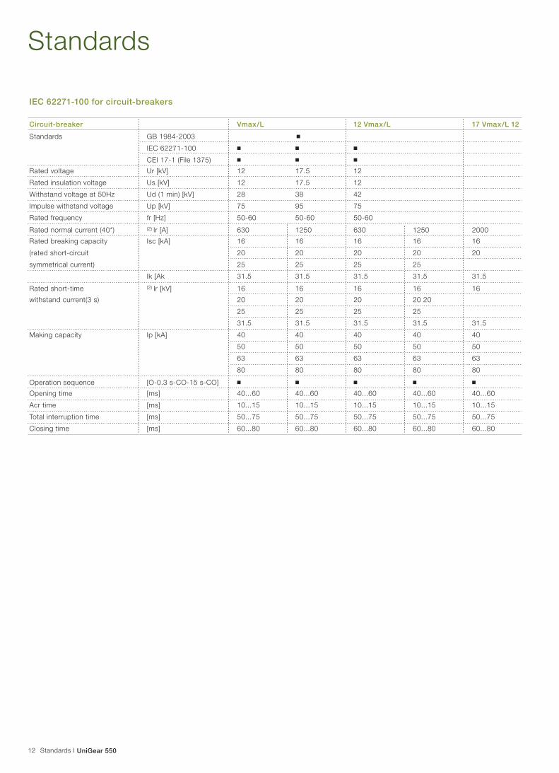
IEC 62271-100 for circuit-breakers
Circuit-breaker Vmax/L 12 Vmax/L 17 Vmax/L 12
Standards GB 1984-2003 ■
IEC 62271-100 ■ ■ ■
CEI 17-1 (File 1375) ■ ■ ■
Rated voltage Ur [kV] 12 17.5 12
Rated insulation voltage Us [kV] 12 17.5 12
Withstand voltage at 50Hz Ud (1 min) [kV] 28 38 42
Impulse withstand voltage Up [kV] 75 95 75
Rated frequency fr [Hz] 50-60 50-60 50-60
Rated normal current (40*) (2) lr [A] 630 1250 630 1250 2000
Rated breaking capacity Isc [kA] 16 16 16 16 16
(rated short-circuit 20 20 20 20 20
symmetrical current) 25 25 25 25
Ik [Ak 31.5 31.5 31.5 31.5 31.5
Rated short-time (2) Ir [kV] 16 16 16 16 16
withstand current(3 s) 20 20 20 20 20
25 25 25 25
31.5 31.5 31.5 31.5 31.5
Making capacity Ip [kA] 40 40 40 40 40
50 50 50 50 50
63 63 63 63 63
80 80 80 80 80
Operation sequence [O-0.3 s-CO-15 s-CO] ■ ■ ■ ■ ■
Opening time [ms] 40...60 40...60 40...60 40...60 40...60
Acr time [ms] 10...15 10...15 10...15 10...15 10...15
Total interruption time [ms] 50...75 50...75 50...75 50...75 50...75
Closing time [ms] 60...80 60...80 60...80 60...80 60...80

13
Uses and features
UniGear 550 I Uses and features
UniGear 550 units are designed to be used in conjunction with the following instruments:■ Ring core-type CTs (standard)■ Block-type CTs (optional)■ Bushing-type CTs (optional)■ Ring-core type CTs
With the advent of new digital protection and measuring
instruments, the use of low-power measuring instruments can
be easily extended to primary distribution switchgear.
The CTs are fixed to a support, i.e. a CT rod, inside the
switchgear which is positioned above the cable terminals. This
ensures the CTs remain unaffected by the number of cables,
cross sections or terminals used.
Each CT rod is designed to accommodate a maximum of
two CTs per phase (metering and protection) and it has the
following dimensional constraints:
■ A minimum internal diameter of 59 mm
■ A maximum external diameter of 200 mm
■ A maximum height of 100 mm
Block-type CTsAs an alternative to the above specified current measuring
instruments, a dedicated combination of block-type current
transformers, current sensors and combi-sensors can be used.
These are used in case of special requirements, such as fiscal
metering on incoming feeders (Class 0.2), differential protection
on line feeders, etc.
The use of block-type CTs will allow for the application of ring
core-type CTs on cables.
Bushing-type current transformersIn a large part of the market, especially among those who
apply BS concepts, the bushing-type CT is very common.
Earthing switch ST1-UGThe UniGear 550 panel is equipped with the patented earthing
switch type ST1-UG, which features a rectilinear movement.
The switch is fitted with a snap-action operation mechanism
for positive high-speed closing. It is dimensioned to conduct
the rated short-circuit current when closed under load conditions.
The speed of the snap-action closing operation is independent
of the controls.
The switch is equipped with an earthing blade which connects
the three phases to the earthing pins located on the copper bars
of the cable connecting system. The earthing bar is electrically
connected to ground by a standard copper conductor.
The closing mechanism of the earthing switch functions
independently of the rotation of the drive shaft, and the
switching speed and torque achieved are independent of
the action of the operating mechanism. During the opening
process, however, the toggle springs have no effect on the
speed of contact separation.
A manual operating lever is provided to operate the switch.
The switch has been tested for two closing operations at
100% of the rated short-circuit current.
The device is provided with auxiliary switches, operated by
the rod mechanism, to indicate the status (open or closed) of
the switch.
Other components, such as a locking magnet, padlock, and
key locks for the open and closed positions are available on
request.
1 Ring core-type CT | 2 Block-type CT | 3 Bushing-type CT | 4 Earthing switch ST1-UG
1 2 3 4

14
Feeder protection
Feeder protection I UniGear 550
GeneralThe protection functions can be divided into two major groups:
(1) Those that trip the circuit breaker of the faulted feeder if a
short circuit, or an earth fault, for example, occurs.
(2) Protection functions that monitor the operation of the
feeder and the rest of the network. voltage, frequency and
overload protection functions (alarming/tripping) are typical
monitoring functions.
The basic requirements of a protection system are adequate
sensitivity and speed of operation, taking into account the
minimum and maximum fault currents occurring in the intelligent
electronic device (IED)-such as the REF615-locations,
selectivity, monitoring inrush currents and the thermal and
mechanical strength of the lines behind the relaying point.
In many cases, the above requirements can be fulfilled with
nondirectional/directional current or multi-staged impedance
measuring functions.
The purpose of an over-and under-voltage protection system
is to monitor the voltage level of the network. If the voltage
level deviates from the target value by more than the permitted
margin for a specific period of time, the voltage protection
system limits the duration of the fault and any resulting stress
on the mechanism.
To prevent major outages due to frequency disturbances,
the substations are usually equipped with under-frequency
protection relays, which in turn control various load-shedding
schemes.
These are just a few examples of the main protection functions
for feeders. more details can be found in the technical
documentation produced for ABB protection relays.
Applications and featuresDepending on the needs of the customer, a suitable IED type
can be selected and configured in a way that provides an
overall solution for different feeder types.
Generally, the required protection functionality of the feeder
types mentioned above differs greatly depending on the
characteristics of the fault current sources and the types of
advanced functions that may be needed to fulfill the basic
requirements of the protection application. A few examples
will now be given to illustrate the requirement level.
Fig. 1: Comparison of standard and high requirement feeders

15UniGear 550 I Feeder protection
Recommended productsABB supplies a wide range of feeder protection relays and
terminals to fulfill the requirements of each unique application.
For an application with standard requirements and a need
for additional features, the REF615, REX521 units are
excellent choices. for applications with higher functionality
requirements, the multifunction terminals REF54_ should be
selected.
Fig. 2 Typical standard feeder I Fig. 3 Typical high requirement feeder
Fig. 2 Fig. 3
1) Optional intermittent E/F protection

16
Transformer protection
Transformer protection I UniGear 550
GeneralThe power transformer is an important component and one
of the most valuable individual units in the power distribution
network. A highly reliable power transformer is therefore of
particular importance in preventing disturbances in the power
distribution system.
Although high-quality power transformers are highly reliable,
faults including insulation breakdowns sometimes occur.
These faults, which appear as short circuits and/or earth
faults generally cause severe damage to the windings and
transformer core. The damage is proportional to the fault
clearing time so the power transformer must be disconnected
as quickly as possible. The power transformer has to be
transported to a workshop for repair, which is a very time-
consuming process.
The operation of a power network in which the power
transformer is out of service is always cumbersome.
Therefore, a power transformer fault often constitutes a more
severe power system fault than a line fault, which usually can
be rectified rather quickly. It is therefore extremely important
that fast and reliable protection relays are used to detect
transformer faults and initiate tripping.
The size, voltage level and importance of the power
transformer determine the extent and choice of the monitoring
and protection devices used to limit the damage of a
possible fault. When compared to the total cost of the power
transformer and the costs caused by a power transformer
fault, the cost of the protection system is negligible.
Applications and featuresABB divides transformer applications into standard
transformer protection applications (typically<1 MVA) and high
requirement transformer applications (typically>5 MVA).
Basic protection requirements (<1 MVA) include:■ Sudden pressure (buchholz) relay
■ Differential protection
■ Over-current protection
■ Earth fault protection
■ Overload protection
■ Unbalance protection
■ Oil level monitoring
High requirements (>5 MVA) are:■ Sudden pressure (buchholz) relay
■ Differential protection
■ Over-current protection
■ Restricted earth fault (REF) protection
■ Overload protection
■ Unbalance protection
■ Over/Under-voltage protection
■ Over/under-frequency protection
■ Oil-level monitoring

17
Motor protection
UniGear 550 I Motor protection
GeneralMotor protection generally provides over-current, unbalance,
earth-fault and short-circuit protection. However, as well as
electrical faults, one of the worst threats facing motors is
overheating, which comes from improper operation. That is
why the fundamental issue for motors is thermal protection.
ABB's solutions focus on advanced thermal protection that
prevents the improper use of the motors. Thermal overload
protection is needed to protect the motor against both
shortand longtime overload and it is extremely important
for the performance of the motor. Short overload conditions
mainly occur during motor start-up.
There are four crucial elements in thermal motor protection:
(1) Most importantly, the thermal overload protection function
monitors the thermal load and records related events.
(2) A cumulative start-up time counter supporting the overload
protection limits the number of consecutive cold starts.
(3) Thermal stress during any single start-up condition is
monitored by the start-up supervision function, which
protects the motor from becoming locked and extending
start-up times.
(4) The fourth element is thermal protection based on
Resistance. Temperature detector (RTD) sensors. As RTD
sensors directly measure the temperature of the stator
winding, bearings, etc., this type of thermal protection is
especially useful if the motor's cooling system is blocked.
Improper use of running motors does not necessarily break
the equipment, but shortens its lifespan. Therefore, a reliable
and versatile motor protection system not only protects
the motor but it also prolongs its life, which contributes to
improving the return on investment of your motor drive.
Applications and featuresThanks to comprehensive communication protocols, including
the widely used industrial protocols such as Modbus RTU/ASCII
and profibus DP, ABB motor protection relays and terminals
can be easily integrated into various control systems.

18
Motor protection
Motor protection I UniGear 550
Recommended productsThe REF541/543/545 transformer terminals are designed for
the comprehensive protection, control, measurement and
supervision of two-winding power transformers and power
generator transformer blocks in utility distribution networks.
It is suitable for applications where on-load tap-changer
control is required. The functionality for standard transformer
protection is provided in the REF542plus terminal.
Fig. 4 Typical standard transformer protection I Fig.5 Typical high requirement transformer protection
Fig. 4 Fig. 5

19
Communication
UniGear 550 I Communication
GeneralIn the complex world of communication, ABB puts a great
deal of effort into finding communication buses and protocols
that ensure a secure and efficient data flow. In addition to the
recently introduced IEC 61850 protocol, ABB uses LON and
SPA communication buses for communication between relays.
In addition, protocols such as IEC 60870-5-103, modbus,
profibus and DNP 3.0 and OPC interface are available.
Depending on the application area, different protocols are
used according to industry de-facto standards.
Utility applicationsIEC 61850IEC 61850 is a flexible, future-proof standard that adapts to
changing requirements, philosophies and technologies. The
function of the IEC 61850 standard is to ensure essential
features, such as interoperability between devices from
different suppliers, the free allocation of functions, adaptability
to ever-changing communication technology and ease of
engineering and maintenance.
Because of the long-term stability of the IEC 61850 standard,
investments in utilities are safeguarded.
Since its inception, ABB has taken a leading position in
the elaboration of corresponding standards in the field of
substation automation.
SPAThe SPA protocol is supported by all ABB relays and
enables a wide range of distribution automation functions.
It is a proven serial bus that has formed the backbone
communication protocol for ABB relays for many years. The
information content that can be transferred is similar to that of
the IEC 61850. To ensure EMI immunity, the SPA protocol is
run over a fiberoptic network.
LONThe LON protocol is a fast bus-based protocol featuring both
vertical (to a master system) and horizontal communication.
When horizontal communication is used, IEDs are able to
exchange interlocking information, for example, over the
communication bus. This reduces the need for hard wiring
between devices, thus saving costs.
The LON bus runs at a substantially higher speed than the
serial buses. ABB has defined extensions to the basic LON
protocol, enabling any information appearing in distribution
automation to be efficiently and securely transferred.To secure
immunity against EMI disturbances, the LON bus runs over
optical fibers.
IEC 60 870-5-103IEC 60 870-5-103 is a standard protocol designed exclusively
for communication between protection IEDs and a master
system. Allowing IEDs of different vendors to be connected
to a common master system, it is widely supported within
distribution automation. The range of information that can be
transmitted with the IEC 60 870-5-103 protocol is smaller
than the information range available through the LON, SPA
and IEC 61850 protocols.
DNP V3.0The DNP protocol, based on the IEC 60 870 standard family,
was originally developed by a single vendor, but has now
evolved into an open standard controlled by a user group.
It is designed for local communication within a substation,
between a protection IED and an RTU (which forwards
information to a remote SCADA system). Additionally, protection
IEDs can be connected directly to a remote system using
this protocol. The DNP has a multitude of options enabling
it to be optimized for different types of applications and
communication environments (it can, for instance, be optimized
to run over a slow communication link).

20
Industrial applications
Industrial applications I UniGear 550
Profibus DP V1Profibus is a major de-facto standard for connectivity to
industrial systems. All ABB relays can be connected to
Profibus master systems using the SPA-ZC 302.
SPA/Profibus converter. The SPA-ZC 302 supports the
Profibus DP V1 protocol and can handle up to 16 SPA
devices. The speed of the Profibus is comparable to that of
LON and it is substantially higher than the speed of serial
protocols. To ensure EMI immunity, Profibus runs over a
double-shielded twisted pair cable. Profibus is generally used
when protected IED information is to be transmitted to a
controller or PLC.
ModbusThe modbus protocol was first introduced by modicon
Inc. and is a widely accepted communication standard for
industrial controllers and PLCs. It is a serial protocol designed
for the transfer of binary and numeric data in a generic format.
The modbus as such does not recognize the data model of a
distribution automation application (as. the IEC 61850 does).
Modeling is done in the application of the modbus master
system. Modbus typically uses a twisted pair RS-485 bus
network as a transmission medium.
OPCOPC is commonly used to interconnect systems in industrial
automation applications. A data exchange system using OPC
consists of an OPC server (which provides data and services)
and an OPC client (which receives data from and uses the
services of the OPC server). The OPC server and the OPC
client are both software components running on PCs. The
interaction between an OPC server and an OPC client can
take place either locally in one PC or over a LAN/WAN
computer network (in the latter case using DCOM as the
intermediate protocol). Data from protection IEDs can be
made available in different ways through an OPC interface.
One option is to use the SPA/OPC or LON/OPC servers,
which collect data from protection IEDs using LON or SPA and
make the data available in the OPC environment.
Another option is to connect the protection IEDs to the
COM610 gateway. Any data in the COM610 can be made
available to an OPC client.
OPC is usually used when the data from protection IEDs is
to be transmitted directly to a control system (as opposed to
profibus and modbus that usually supply data to a controller
or a PLC). Via PC or over a LAN/WAN computer network (in
the latter case using DCOM as the intermediate protocol),
data from protection IEDs can be made available in different
ways through an OPC interface. One option is to use the SPA/
OPC or LON/OPC servers, which collect data from protection
IEDs using LON or SPA and make the data available within
the OPC environment. Another option is to connect the
protection IEDs directly to the COM610, thereby making data
available to an OPC client. OPC is usually used when the data
from protection IEDs is to be transmitted directly to a control
system (as opposed to profibus and modbus that usually
supply data to a controller or a PLC).

21UniGear 550 I Arc protection
Arc protection
GeneralAn electric arc short-circuit in a switchgear installation is
normally caused by a foreign object entering the cubicle or by
a component failure. The arc causes explosion-like heat and
pressure that can extensively damage the switchgear and the
operating personnel.
An adequate arc protection system protects a substation
against arc faults by minimizing the burning time of the arc,
thus preventing excessive heat and damage. It minimizes
material damage and allows power distribution to be smoothly
and safely restored. The system can also bring cost benefits
even before an arc fault occurs. As older switchgear is more
prone to arc faults, an arc protection system will effectively
extend the life of your switchgear and make more of your
investment.
But more importantly, arc-protection technology can help save
lives.
Applications and featuresSources of arcing may be insulation faults, the incorrect
operation of devices, defective bus or cable joints, over-
voltage, corrosion, pollution, moisture, ferroresonance (in
instrument transformers) and even ageing due to electrical
stress. Most of these arc-fault sources could be prevented by
sufficient maintenance. However, in spite of the precautions
taken, human errors can lead to arc faults.
Time is critical when it comes to detecting and minimizing
the effects of an electric arc. An arc fault lasting 500 ms may
severely damage the installation. If the burning time of the
arc is less than 100 ms the damage is often limited, but if the
arc is extinguished in less than 35 ms, the effect goes almost
unnoticed.
Generally applied protection relays are not fast enough to
ensure safe fault clearance times when arc faults occur.
The operation time of the over-current relay controlling the
incoming circuit breaker may, for instance, have to be delayed
by hundreds of milliseconds for selectivity reasons. This delay
can be avoided by installing an arc-protection system.
The total fault clearance time can be reduced to a maximum
of 2.5 ms, plus the circuit breaker's contact travel time.
Furthermore, in cases of cable compartment faults, auto-
reclosures can be eliminated by employing arc protection.
Recommended productsThe arc protection system, REA101, with its extension units,
REA103, REA105 and REA107, are designed to be used
for the protection of medium and low-voltage air-insulated
switchgear. The central unit type REA101 can operate
independently or together with other REA101 units.
With tripping times as low as 2.5 ms, REA is the fastest arc
protection system on the market.
REAis equipped with a fast integrated over-current sensing
element and it works independently of other feeder protection
units. The REF610 feeder protection relay includes an optional
arc protection function for the feeder cubicle.
Fig. 8 Typical setup with REA101 and REA103 subunits
3
Trip
Trip
REA 101
REA 103 REA 103
Light

22
Selection guide
Selection guide I UniGear 550
Application REF615 REX521 REF54_ RET 54_ REM54_ REM610 REA10_
Feeder application ■ ■
High requirement feeder application ■ ■
Transformer application ■ ■
High requirement transformer application ■
Motor protection ■ ■ ■ ■
High requirement motor application ■
Generator & synchronous motor ■
Distance protection ■
Arc protection for feeder cubicle ■ ■
Arc protection system
Communication
IEC 60870-5-103 ■ ■ ■ ■ ■
IEC 61850 ■* ■* ■* ■* ■* ■*
DNP 3.0 ■ ■ ■ ■
SPA ■ ■ ■ ■ ■ ■
LON ■ ■* ■ ■ ■ ■*
Modbus ■ ■ ■ ■ ■
Profibus ■* ■* ■* ■* ■* ■*
Additional functions
Fault locator ■
Web interface ■
CAN interface ■
On load tap chemger control ■
Disturbance recording ■ ■ ■ ■ ■ ■
Withdrawable release mechanics ■ ■
Condition monitoring ■ ■ ■ ■ ■
Single line diagram HMI** ■ ■ ■
Remote contro ■ ■ ■ ■
Power quality monitoring ■ ■
Sensor inputs ■ ■ ■ ■
Auto re-closure 5 shots 3 shots 5 shots
RTD*** inputs 8 8 6
* With interface adapter
** HMI-human machine Interface
***RTD-resistive temperature detector

23
REF542plus multifunction protectionand control unit
UniGear 550 I REF542plus multifunction protection and control unit
The REF542plus unit integrates all the secondary functions
relevant to a switchgear unit in a single module fitted with a
watchdog.
Thanks to the flexibility of its software, the unit is able to
satisfy a vast range of installation requirements. The high
level of functionality of the REF542plus unit is supported by a
simple and easy-to-use user interface.
With a REF542plus unit, each medium-voltage UniGear panel
becomes an integrated and independent unit able to carry out
functions such as protection, measurement, control, signaling,
interlocking, automation and communication.
The REF542plus is characterized by■ A single interface between the switchgear and operator for
the installation panels: feeder, transformer, motor,generator,
power correction banks, bus-tie and measurements units.-
Single type of spares parts and accessories: a single
hardware unit
■ Low maintenance. Good preventive maintenance severely
limits the faults caused by tampering and errors
■ The functions can be easily modified and upgraded,
even when the switchgear is in service, by means of unit
configuration software switchgear
HardwareThe device central unit is housed inside the auxiliary
compartment of the switchgear while the user interface is
located on the door of this compartment.
The two pieces are connected together by means of a
simple communication cable. The user interface can be
replaced while the central unit remains in service and all the
measurement, control and protection functions are guaranteed
during maintenance work.
All the connections are made by means of plug socket
connectors to optimize service and maintenance operations.
Machine-user interfaceThe UniGear switchgear is easily operated via the user
interface of the REF542plus unit.
All the apparatus control operations, measurement readouts,
detection of signals and parameterization of functions can be
carried out directly from the front of the unit, or by means of a
laptop computer connected to the optic communication gate
located on the front.
Central unitThe REF542plus central unit consists of several electronic
modules:
■ Feeder. The apparatus is fitted with a multi-voltage
internal feeder and can operate from 48 Vdc to 220 Vdc.
Thanks to its digital technology, consumption is very low
■ Digital inputs. Each unit is fitted with a minimum of
14 digital inputs to interface with the apparatus-circuit-
breaker and earthing switch-contained in the switchgear.
These can be increased to a maximum of 42. They
operate between 20 Vdc and 250 Vdc. and are freely
programmable.
■ Digital outputs. These consist of free contacts made
available by bi-stable relays. Each unit has at least 8
outputs to operate the switchgear apparatus and the
minimum signals required. The number of outputs can be
increased to a maximum of 24. They operate up to
250 Vdc/ac. and are freely programmable.
- The output that controls circuit-breaker opening can also
carry out control of circuit continuity.
- By means of the static outputs with which it is fitted
(from 1 to a maximum of 3), it is possible to interface
conventional supervision systems by means of active
and reactive power measurements with impulse emitter.
■ Analogue inputs. Each unit is fitted with 8 analogue
inputs needed to carry out measurements and protections.
- Signals coming from conventional CTs (1 A and 5 A) and
VTs (100 V and 110 V) or from measurement sensors
(based on a Rogowski coil and resistive divider) can be
acquired.
■ Analogue outputs. The 4 analogue outputs the unit can
be provided with make it possible to interface conventional
supervision systems by means of the integrated
measurement functions. Each output can be freely
programmed as 0...20 mA or 4...20 mA.

24
REF542plus multifunction protectionand control unit
REF542plus multifunction protection and control unit I UniGear 550
CommunicationThe REF542plus unit can be connected to supervision and
process systems by means of an integrated communication
function.
This turns the apparatus into a window through which the
system accesses all the switchgear information and makes
the following functions possible:
■ Monitoring
■ Control
■ Parameterization of the protection functions
■ Measurements
■ Monitoring of all operating apparatus
■ Disturbance oscillography
The following protocols are available for connection to the
supervision and automation systems:
■ ABB SPA-bus
■ LON-bus in accordance with ABB lon application guide
(LAG 1.4)
■ IEC 60870-5-1 03 (in accordance with VDEW specifi cations)
■ MODBUS RTU
Use of the LON-bus protocol and relative LIB 542 library
allows the REF542plus unit to be integrated into ABB
supervision systems.
Using the hardware configuration with two gates and the
MODBUS RTU protocol, it is possible to create redundant
system architectures, or independent connections to two
different systems, for example, a supervisory control and data
acquisition system (SCADA) and a process distributed control
system (DCS).
SynchronizationThe REF542plus unit can be connected to an external master
clock (typically a GPS) by means of a dedicated optic input for
synchronization. When synchronized using this method, the
REF542plus units guarantee chronological recording of events
within a maximum time of 1 ms. The protocol accepted is
IRIG-B.

25
Automatic transfer systems
UniGear 550 I Automatic transfer systems
Automatic transfer systems (ATS) are used to give maximum
service continuity by ensuring an uninterrupted supply of
power. This is possible using various systems based on
different kinds of techniques.
The most common systems are described below with relevant
average transfer times of.
The first two systems on the list above are the simplest and
can be made with conventional logics and instruments. They
guarantee average transfer times and can therefore be used in
installations where voltage gaps are not particularly critical.
On the other hand, the other two systems:
■ Delayed: 1500 ms
■ Depending on the residual voltage: 400 ms-1200 ms
■ Synchronised (ATS): 200 ms-500 ms
■ High speed (HSTS): 30 ms-120 ms
Synchronized ATS and ahigh speed transfer system (HSTS)
require a microprocessor-based apparatus with high
technological content. They guarantee fast transfer times
and are generally applied in plants where the process times
are particularly critical. Slower transfers times would cause
serious malfunctions or even stoppages.
ABB is able to offer all the transfer systems, from the simplest
to the most complex.
The REF542plus unit can be used in medium-voltage
switchgear to manage automatic and manual transfer between
two different incoming feeders.
The time needed for automatic transfer using the REF542plus
unit is between 200 ms and 300 ms (including the circuit-
breaker operating times). This time can vary depending on
the complexity of the software transfer logics. Switchgear
equipped with suitably programmed REF542plus units are
considered complete and efficient systems able to manage
transfer between one power supply system and an alternative
one or reconfigure the network, passing from double radial
distribution to a simple system, in a fully automatic way.
It is also possible to carry out the same operation manually
from a remote control station, or from the front of the
switchgear under the supervision of user personnel. Manual
transfer first involves paralleling two parts of the power
system. By means of the synchronism control function
“synchro-check” (ANSI protection code 25) implemented
from the REF542plus , the power supply lines are closed
simultaneously as the voltage vectors become synchronized
before being disconnected when the transfer has taken place.
The applications described do not.........
Single-line diagram of UniGear switchgear with REF542plus architecture. This configuration is suitable for carrying out automatic and manual transfer (ATS), as well as switchgear protections and measurements.

26
Typical units and technical data
Typical units and technical data I UniGear 550
Single-line diagram of the typical units1 IF-incoming/outgoing feeder | 2 BT-bus tie | 3 R-bus riser | 4 RM-bus riser with measurements5 M-measurements | 6 IFD-direct incoming/Outgoing | 7 IFDM-direct incoming/outgoing with measurement

27UniGear 550 I Typical units and technical data
Single-line diagram of the busbar applications1 Current transformers | 2 Voltage transformers | 3 Duct entry | 4 Earthing switch
Graphical symbols1 Circuit-breaker | 2 Contactor | 3 Switch | 4 Isolating bar | 5 Socket and plug | 6 Voltage transformers | 7 Current transformers | 8 Fuse9 Earth | 10 Cable entry | 11 Busbar entry
...31.5 kA
IF
FM
BT
R
RM
M
IFD
IFDM
DF
Depth(mm)
Rated current (A)
Incoming/outgoing
Incoming/outgoing with measurements
Bus-tie
Riser
Riser with measurements
Measurements
Direct incoming/outgoing
Direct incoming/outgoing with measurement
Switch-disconnector unit
550
630 1250 1600 2000
■ ■ ■ ■
■ ■ ■ ■
■ ■ ■ ■
■ ■
■ ■
■ Altemative solutions
Technical data

28
Typical units and technical data
Typical units and technical data I UniGear 550
■ Width: 550 mm
■ Depth: 630 A~1250 A: 1340 mm
1600 A~2000 A: 1390 mm■ Deeper: 1650 mm
■ Height: 2200 mm
■ Height with gas exhaust duct: 2675 mm
Unit compartmentsA: ApparatusB: Main busbarsC: FeederD: InstrumentsE: Gas exhaust duct
E
A
C
BD
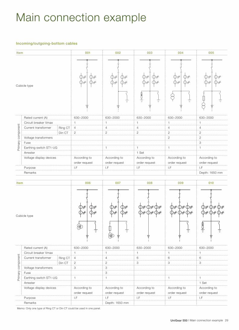
29UniGear 550 I Main connection example
Main connection example
Incoming/outgoing-bottom cables
Item 001 002 003 004 005
630~2000
1
4
2
According to
order request
I.F
630~2000
1
4
2
1
According to
order request
I.F
630~2000
1
4
2
1
1 Set
According to
order request
I.F
630~2000
1
4
2
2
1
According to
order request
I.F
630~2000
1
4
2
2
3
1
According to
order request
I.F
Depth: 1650 mm
Cubicle type
Ring CT
Din CT
Rated current (A)
Circuit breaker Vmax
Current transformer
Voltage transformers
Fuse
Earthing switch ST1-UG
Arrester
Voltage display devices
Purpose
Remarks
Pri
mary
co
mp
on
en
t
Item 006 007 008 009 010
630~2000
1
4
2
3
1
According to
order request
I.F
630~2000
1
4
2
3
3
1
According to
order request
I.F
Depth: 1650 mm
630~2000
1
6
3
According to
order request
I.F
630~2000
1
6
3
1
According to
order request
I.F
630~2000
1
6
3
1
1 Set
According to
order request
I.F
Cubicle type
Ring CT
Din CT
Rated current (A)
Circuit breaker Vmax
Current transformer
Voltage transformers
Fuse
Earthing switch ST1-UG
Arrester
Voltage display devices
Purpose
Remarks
Pri
mary
co
mp
on
en
t
Memo: Only one type of Ring CT or Din CT could be used in one panel.

30 Main connection example I UniGear 550
Main connection example
Item 011 012 013 014 015
630~2000
1
6
3
2
1
According to
order request
I.F
630~2000
1
6
3
2
3
1
According to
order request
I.F
Depth: 1650 mm
630~2000
1
6
3
3
1
According to
order request
I.F
630~2000
1
6
3
3
3
1
According to
order request
I.F
Depth: 1650 mm
630~2000
1
4
2
1 Set
According to
order request
I.F
Cubicle type
Ring CT
Din CT
Rated current (A)
Circuit breaker Vmax
Current transformer
Voltage transformers
Fuse
Earthing switch ST1-UG
Arrester
Voltage display devices
Purpose
Remarks
Pri
mary
co
mp
on
en
t
Item 016 017 018 019 020
630~2000
1
6
3
1 Set
According to
order request
I.F
630~2000
1
6
3
2
3
1
1 Set
According to
order request
I.F
Depth: 1650 mm
630~2000
1
6
3
3
3
1
1 Set
According to
order request
I.F
Depth: 1650 mm
630~2000
1
4
2
2
3
1
1 Set
According to
order request
I.F
Depth: 1650 mm
630~2000
1
4
2
3
3
1
1 Set
According to
order request
I.F
Depth: 1650 mm
Cubicle type
Ring CT
Din CT
Rated current (A)
Circuit breaker Vmax
Current transformer
Voltage transformers
Fuse
Earthing switch ST1-UG
Arrester
Voltage display devices
Purpose
Remarks
Pri
mary
co
mp
on
en
t
Memo: Only one type of Ring CT or Din CT could be used in one panel.
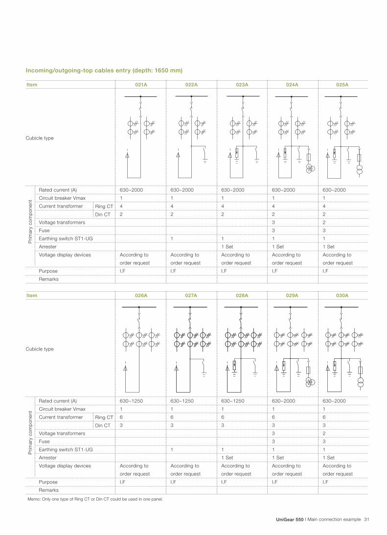
31UniGear 550 I Main connection example
Item 021A 022A 023A 024A 025A
630~2000
1
4
2
According to
order request
I.F
630~2000
1
4
2
1
According to
order request
I.F
630~2000
1
4
2
1
1 Set
According to
order request
I.F
630~2000
1
4
2
3
3
1
1 Set
According to
order request
I.F
630~2000
1
4
2
2
3
1
1 Set
According to
order request
I.F
Cubicle type
Ring CT
Din CT
Rated current (A)
Circuit breaker Vmax
Current transformer
Voltage transformers
Fuse
Earthing switch ST1-UG
Arrester
Voltage display devices
Purpose
Remarks
Pri
mary
co
mp
on
en
t
630~1250
1
6
3
According to
order request
I.F
630~1250
1
6
3
1
According to
order request
I.F
630~1250
1
6
3
1
1 Set
According to
order request
I.F
630~2000
1
6
3
3
3
1
1 Set
According to
order request
I.F
630~2000
1
6
3
2
3
1
1 Set
According to
order request
I.F
Cubicle type
Ring CT
Din CT
Rated current (A)
Circuit breaker Vmax
Current transformer
Voltage transformers
Fuse
Earthing switch ST1-UG
Arrester
Voltage display devices
Purpose
Remarks
Pri
mary
co
mp
on
en
t
Memo: Only one type of Ring CT or Din CT could be used in one panel.
Incoming/outgoing-top cables entry (depth: 1650 mm)
Item 026A 027A 028A 029A 030A

32 Main connection example I UniGear 550
Main connection example
630~2000
1
4
2
1 Set
According to
order request
I.F
630~2000
1
6
3
1 Set
According to
order request
I.F
Cubicle type
Ring CT
Din CT
Rated current (A)
Circuit breaker Vmax
Current transformer
Voltage transformers
Fuse
Earthing switch ST1-UG
Arrester
Voltage display devices
Purpose
Remarks
Pri
mary
co
mp
on
en
t
Cubicle type
Ring CT
Din CT
Rated current (A)
Circuit breaker Vmax
Current transformer
Voltage transformers
Fuse
Earthing switch ST1-UG
Arrester
Voltage display devices
Purpose
Remarks
Pri
mary
co
mp
on
en
t
Memo: Only one type of Ring CT or Din CT could be used in one panel.
Item 031A 032A 033A 034A 035A
Item 036A 037A 038A 039A 040A

33UniGear 550 I Main connection example
Incoming/outgoing-top busbar entry (depth: 1650 mm)
630~2000
1
4
2
According to
order request
I.F
630~2000
1
4
2
1
According to
order request
I.F
630~2000
1
4
2
1
1 Set
According to
order request
I.F
630~2000
1
4
2
3
3
1
1 Set
According to
order request
I.F
630~2000
1
4
2
2
3
1
1 Set
According to
order request
I.F
Cubicle type
Ring CT
Din CT
Rated current (A)
Circuit breaker Vmax
Current transformer
Voltage transformers
Fuse
Earthing switch ST1-UG
Arrester
Voltage display devices
Purpose
Remarks
Pri
mary
co
mp
on
en
t
630~1250
1
6
3
According to
order request
I.F
630~1250
1
6
3
1
According to
order request
I.F
630~1250
1
6
3
1
1 Set
According to
order request
I.F
630~2000
1
6
3
3
3
1
1 Set
According to
order request
I.F
630~2000
1
6
3
2
3
1
1 Set
According to
order request
I.F
Cubicle type
Ring CT
Din CT
Rated current (A)
Circuit breaker Vmax
Current transformer
Voltage transformers
Fuse
Earthing switch ST1-UG
Arrester
Voltage display devices
Purpose
Remarks
Pri
mary
co
mp
on
en
t
Memo: Only one type of Ring CT or Din CT could be used in one panel.
Item 021B 022B 023B 024B 025B
Item 026B 027B 028B 029B 030B

34 Main connection example I UniGear 550
Main connection example
630~2000
1
4
2
1 Set
According to
order request
I.F
630~2000
1
6
3
1 Set
According to
order request
I.F
Cubicle type
Ring CT
Din CT
Rated current (A)
Circuit breaker Vmax
Current transformer
Voltage transformers
Fuse
Earthing switch ST1-UG
Arrester
Voltage display devices
Purpose
Remarks
Pri
mary
co
mp
on
en
t
Cubicle type
Ring CT
Din CT
Rated current (A)
Circuit breaker Vmax
Current transformer
Voltage transformers
Fuse
Earthing switch ST1-UG
Arrester
Voltage display devices
Purpose
Remarks
Pri
mary
co
mp
on
en
t
Memo: Only one type of Ring CT or Din CT could be used in one panel.
Item 031B 032B 033B 034B 035B
Item 036B 037B 038B 039B 040B

35UniGear 550 I Main connection example
Bus-tie
Item 051 052 053 054 055
630~2000
1
4
2
BT
630~2000
1
4
2
1
BT
630~1250
1
4
2
1 Set
BT
Cubicle type
Ring CT
Din CT
Rated current (A)
Circuit breaker Vmax
Current transformer
Voltage transformers
Fuse
Earthing switch ST1-UG
Arrester
Voltage display devices
Purpose
Remarks
Pri
mary
co
mp
on
en
t
Item 056 057 058 059 060
630~2000
1
6
3
BT
630~2000
1
6
3
1
BT
630~1250
1
6
3
1 Set
BT
Cubicle type
Ring CT
Din CT
Rated current (A)
Circuit breaker Vmax
Current transformer
Voltage transformers
Fuse
Earthing switch ST1-UG
Arrester
Voltage display devices
Purpose
Remarks
Pri
mary
co
mp
on
en
t
Memo: Only one type of Ring CT or Din CT could be used in one panel.

36 Main connection example I UniGear 550
Main connection example
Measurement
Item 061 062 063 064 065
630~1250
2
2
3
M
630~1250
2
2
3
M
630~2000
2
2
3
M
630~2000
2
2
3
M
630~2000
2
2
3
M
Cubicle type
Rated current (A)
Circuit breaker Vmax
Current transformer Din CT
Voltage transformers
Fuse
Earthing switch ST1-UG
Arrester
Voltage display devices
Purpose
Remarks
Pri
mary
co
mp
on
en
t
Item 066 067 068 069 070
Cubicle type
Rated current (A)
Circuit breaker Vmax
Current transformer Din CT
Voltage transformers
Fuse
Earthing switch ST1-UG
Arrester
Voltage display devices
Purpose
Remarks
Pri
mary
co
mp
on
en
t

37UniGear 550 I Main connection example
Measurement (VTs)
Item 081 082 083 084 085
2
3
P
3
3
P
2
3
1 Set
P
3
3
1 Set
P
Cubicle type
Rated current (A)
Circuit breaker Vmax
Current transformer
Voltage transformers
Fuse
Earthing switch ST1-UG
Arrester
Voltage display devices
Purpose
Remarks
Pri
mary
co
mp
on
en
t
Item 086 087 088 089 090
630~1250
2
3
1 Set
P+(1)
630~1250
3
3
1 Set
P+(1)
630~1250
2
3
1 Set
P+R
630~2000
2
3
P+R
630~2000
3
3
P+R
Cubicle type
Rated current (A)
Circuit breaker Vmax
Current transformer
Voltage transformers
Fuse
Earthing switch ST1-UG
Arrester
Voltage display devices
Purpose
Remarks
Pri
mary
co
mp
on
en
t

38 Main connection example I UniGear 550
Main connection example
Item 091 092 093 094 095
630~1250
2
3
1 Set
P+R
630~1250
3
3
1 Set
P+R
Cubicle type
Rated current (A)
Circuit breaker Vmax
Current transformer
Voltage transformers
Fuse
Earthing switch ST1-UG
Arrester
Voltage display devices
Purpose
Remarks
Pri
mary
co
mp
on
en
t
Item 096 097 098 099 100
Cubicle type
Rated current (A)
Circuit breaker Vmax
Current transformer
Voltage transformers
Fuse
Earthing switch ST1-UG
Arrester
Voltage display devices
Purpose
Remarks
Pri
mary
co
mp
on
en
t
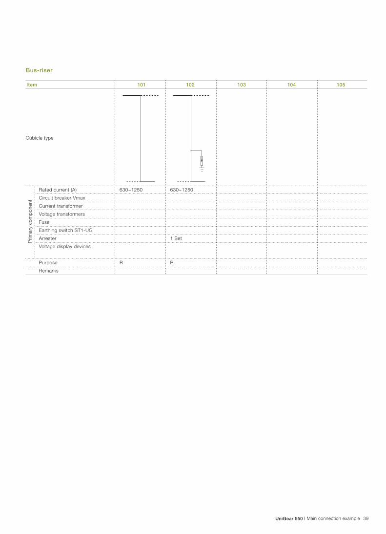
39UniGear 550 I Main connection example
Bus-riser
Item 101 102 103 104 105
630~1250
R
630~1250
1 Set
R
Cubicle type
Rated current (A)
Circuit breaker Vmax
Current transformer
Voltage transformers
Fuse
Earthing switch ST1-UG
Arrester
Voltage display devices
Purpose
Remarks
Pri
mary
co
mp
on
en
t
Contact us
We reserve the right to make changes in the course of
technical developmentABB Xiamen Electrical Controlgear Co., Ltd.No. 559, Weili Road, Xiamen, Fujian, P.R.China
Tel: +86 592 630 3000
Fax: +86 592 630 3002
Zip Code: 361009
www.abb.com.cn
Pu
blic
ati
on
nu
mb
er:
1V
XA
15
00
02
, E
N,
20
14
01


