The AquaSnap chiller is an effective all-in-one package that is easy to install and easy to own. AquaSnap chillers operate quietly and efficiently. Value-added features include:• Rotary scroll compression• HFC Puron® refrigerant (R-410A)• Low-sound AeroAcoustic™ fan system• Easy to use ComfortLink controls• Optional integrated hydronic pump
package with VFD (variable frequency drive) compatible motors, with optional VFD on size 070-150 models
• Microchannel condenser coil technology
• Accessory fluid storage tank on size 010-060 models
• Optional digital scroll compressors on size 010-090 models
Features/BenefitsCarrier’s superior chiller design provides savings at initial purchase, at installa-tion, and for years afterward.Costs less right from the startCarrier’s AquaSnap chillers feature a compact, all-in-one package design that installs quickly and easily on the ground or the rooftop. The optional pump and hydronic components are already built in; this costs less than buying and install-ing the components individually. The chiller’s fully integrated and pre-assem-bled hydronic system installs in minutes. No other chiller in this class installs so easily and inexpensively. The preassem-bled and integrated hydronic module uti-lizes top-quality components and pumps to ensure years of reliable operation.
AQUASNAP®
30RAP010-150Air-Cooled Chillers
with PURON® Refrigerant (R-410A)
10 to 150 Nominal Tons(35 to 528 Nominal kW)
ProductData
a30-4827
a30-4826
a30-5347
2
Use of the optional fluid storage tank, available on size 010-060 models, re-duces installation costs and ensures suf-ficient fluid volume is available for close-coupled and process cooling ap-plications. The AquaSnap unit’s high efficiency keeps costs down.
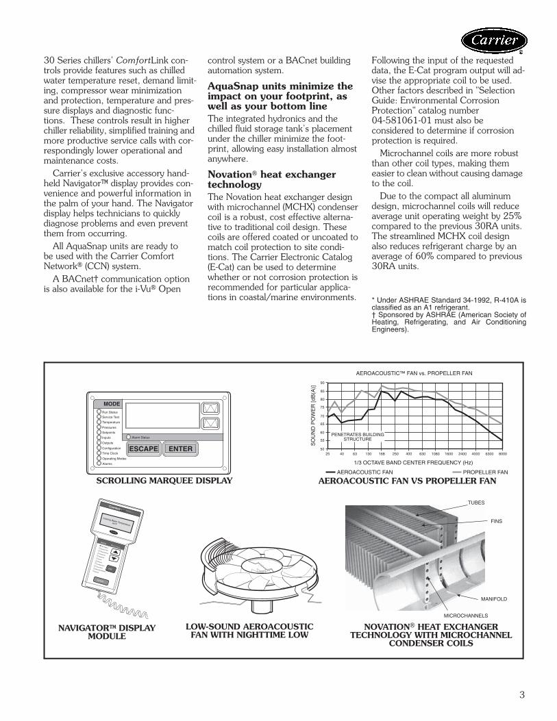
AquaSnap® chillers make noise in the marketplace, not the workplace.The AquaSnap chiller’s low-sound AeroAcoustic™ fan produces up to half the sound level of propeller fans. Much of the noise reduction is in frequencies where noise is most annoying, which makes AquaSnap chillers ideal for sound-sensitive environments. When lower ambient temperatures allow part load operation or during scheduled nighttime operation, the units operate with fewer fans and become even qui-eter. AquaSnap chillers are quiet dur-ing the day and even quieter at night.
The savings will continue to mountBesides costing less to buy and install, AquaSnap chillers are also more af-fordable to operate. Carrier’s AquaSeries chillers are our most efficient air-cooled models. The AquaSnap chiller provides full load EER (Energy Efficiency Ratio) up to 10.5 and IPLV (integrated part load value) up to 15.9. AquaSnap chillers use ultra-quiet, high-efficiency rotary scroll compressors, operated in single (sizes 010 and 015) tandem (sizes 018 to 060), and tan-dem or trio (sizes 070 to 150) per in-dependent circuit for greater efficiency at partial loads.Electronic expansion valve (EXV) allows for precise control through all
operating ranges, resulting in higher efficiency and improved reliability.
Proven reliability that’s built inThousands of AquaSnap chillers arealready in service around the world. This field-proven design is backed by a12-month warranty that includes the hydronic system. The compressors are maintenance-free and protected by an auto-adaptive control that minimizes compressor wear. Unit sizes 035 and up have two independent refrigerant circuits. Year-round operation isstandard, from –20 F (–29 C) (withoptional cooler heater, low ambient control, and wind baffles) to 120 F(50 C).Rotary scroll compressors provide smooth, quiet and reliable operation.
All-in-one packageAquaSnap chillers provide the most comprehensive chilled water circuit available for any air-cooled chiller.Included is a brazed plate directexpansion cooler that may be remote-mounted. The cooler is also completely drainable with factory-installed vents and drains.Electronic thermal-dispersion flow switch is included with the cool-er. The switch is factory installed and tested and contains no moving parts for high reliability.Optional integrated hydronics package is more than just a pump, it is an entire chilled water system,including:• Single/dual pumps up to 15 hp
and 160 ft head• Regular strainer• Cleanout strainer
• Flow regulator• Freeze protection to –20 F (–29 C)
and VFD compatibility on all models The factory-installed and tested hy-
dronics package provides faster, sim-pler and less expensive installation.Digital scroll compressors are available as a factory-installed option on sizes 010 to 090. These allow for incremental unloading with capacity modulation to better match building load when compared to standard scroll compressors.
Environmentally soundCarrier’s Puron® refrigerant (R-410A) enables you to make a responsible de-cision in the protection of the earth’s ozone layer. Puron refrigerant is an HFC refrigerant that does not contain chlorine that is damaging to the ozone layer. Puron refrigerant is unaffected by the Montreal Protocol. Puron refrig-erant is a safe, non-toxic*, efficient and environmentally sound refrigerant for the future.
Durable constructionThe 30RAP chillers have a structurally sound base that can be point-loaded, therefore, no perimeter base rail is re-quired. All 30RAP units have weather-ized cabinets constructed of heavy-duty galvanized steel with exterior panels painted with corrosion-resistant baked enamel. Inside and outside surfaces are protected to ensure long life and good appearance. The durable, galvanized steel, painted components exceed the requirements of the 500-hour salt spray test per ASTM (American Soci-ety for Testing and Materials) B117.
ComfortLink controls speak your languageThe ComfortLink controls communi-cate in plain English, making it as easy as possible to monitor and control each AquaSnap chiller while accurately maintaining fluid temperatures. The large scrolling marquee display acts as a window into the unit’s operation, providing easy-to-read information about chiller performance and over15 diagnostic functions. Carrier’s
30 Series chillers’ ComfortLink con-trols provide features such as chilled water temperature reset, demand limit-ing, compressor wear minimization and protection, temperature and pres-sure displays and diagnostic func-tions. These controls result in higher chiller reliability, simplified training and more productive service calls with cor-respondingly lower operational and maintenance costs.
Carrier’s exclusive accessory hand-held Navigator™ display provides con-venience and powerful information in the palm of your hand. The Navigator display helps technicians to quickly diagnose problems and even prevent them from occurring.
All AquaSnap units are ready to be used with the Carrier Comfort Network® (CCN) system.
A BACnet† communication option is also available for the i-Vu® Open
control system or a BACnet building automation system.
AquaSnap units minimize the impact on your footprint, as well as your bottom lineThe integrated hydronics and the chilled fluid storage tank’s placement under the chiller minimize the foot-print, allowing easy installation almost anywhere.
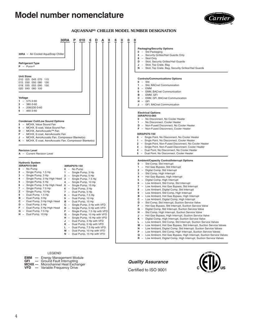
Novation® heat exchanger technologyThe Novation heat exchanger design with microchannel (MCHX) condenser coil is a robust, cost effective alterna-tive to traditional coil design. These coils are offered coated or uncoated to match coil protection to site condi-tions. The Carrier Electronic Catalog (E-Cat) can be used to determine whether or not corrosion protection is recommended for particular applica-tions in coastal/marine environments.
Following the input of the requested data, the E-Cat program output will ad-vise the appropriate coil to be used. Other factors described in "Selection Guide: Environmental Corrosion Protection" catalog number 04-581061-01 must also be considered to determine if corrosion protection is required. Microchannel coils are more robust than other coil types, making them easier to clean without causing damage to the coil. Due to the compact all aluminumdesign, microchannel coils will reduce average unit operating weight by 25% compared to the previous 30RA units. The streamlined MCHX coil design also reduces refrigerant charge by an average of 60% compared to previous 30RA units.
NOVATION® HEAT EXCHANGERTECHNOLOGY WITH MICROCHANNEL
CONDENSER COILS
* Under ASHRAE Standard 34-1992, R-410A isclassified as an A1 refrigerant.† Sponsored by ASHRAE (American Society ofHeating, Refrigerating, and Air ConditioningEngineers).
4
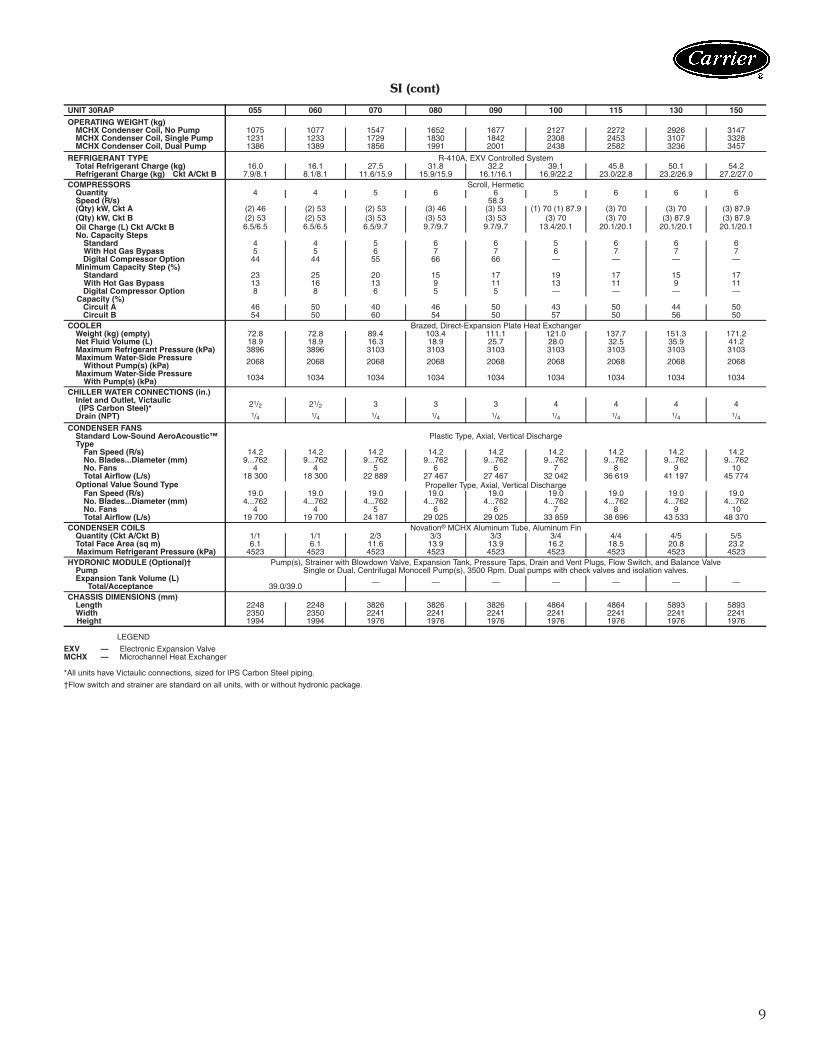
AQUASNAP® CHILLER MODEL NUMBER DESIGNATION
LEGENDEMM — Energy Management ModuleGFI — Ground Fault InterruptingMCHX — Microchannel Heat ExchangerVFD — Variable Frequency Drive
Hydronic System30RAP010-0600 – No Pump2 – Single Pump, 1.5 Hp3 – Single Pump, 3 Hp4 – Single Pump, 3 Hp High Head5 – Single Pump, 5 Hp6 – Single Pump, 5 Hp High Head7 – Single Pump, 7.5 HpZ – Single Pump, 10 Hp9 – Dual Pump, 1.5 HpB – Dual Pump, 3 HpC – Dual Pump, 3 Hp High HeadD – Dual Pump, 5 HpF – Dual Pump, 5 Hp High HeadG – Dual Pump, 7.5 HpH – Dual Pump, 10 Hp
Ambient/Capacity Control/Interrupt Options0 – Std Comp, Std Interrupt1 – Hot Gas Bypass, Std Interrupt2 – Digital Comp, Std Interrupt3 – Std Comp, High Interrupt4 – Hot Gas Bypass, High Interrupt5 – Digital Comp, High Interrupt6 – Low Ambient, Std Comp, Std Interrupt7 – Low Ambient, Hot Gas Bypass, Std Interrupt8 – Low Ambient, Digital Comp, Std Interrupt9 – Low Ambient, Std Comp, High InterruptB – Low Ambient, Hot Gas Bypass, High InterruptC – Low Ambient, Digital Comp, High InterruptD – Std Comp, Std Interrupt, Suction Service ValveF – Hot Gas Bypass, Std Interrupt, Suction Service ValveG – Digital Comp, Std Interrupt, Suction Service ValveH – Std Comp, High Interrupt, Suction Service ValveJ – Hot Gas Bypass, High Interrupt, Suction Service ValveK – Digital Comp, High Interrupt, Suction Service ValveL – Low Ambient, Std Comp, Std Interrupt, Suction Service ValvesM – Low Ambient, Hot Gas Bypass, Std Interrupt, Suction Service ValvesN – Low Ambient, Digital Comp, Std Interrupt, Suction Service ValvesP – Low Ambient, Std Comp, High Interrupt, Suction Service ValvesQ – Low Ambient, Hot Gas Bypass, High Interrupt, Suction Service ValvesR – Low Ambient, Digital Comp, High Interrupt, Suction Service Valves
Electrical Options30RAP010-0600 – No Disconnect, No Cooler Heater1 – No Disconnect, Cooler HeaterD – Non-Fused Disconnect, No Cooler HeaterF – Non-Fused Disconnect, Cooler Heater
30RAP070-1500 – No Pump1 – Single Pump, 3 Hp2 – Single Pump, 5 Hp3 – Single Pump, 7.5 Hp4 – Single Pump, 10 Hp5 – Single Pump, 15 Hp6 – Dual Pump, 3 Hp7 – Dual Pump, 5 Hp8 – Dual Pump, 7.5 Hp9 – Dual Pump, 10 HpB – Dual Pump, 15 HpC – Single Pump, 3 Hp with VFDD – Single Pump, 5 Hp with VFDF – Single Pump, 7.5 Hp with VFDG – Single Pump, 10 Hp with VFDH – Single Pump, 15 Hp with VFDJ – Dual Pump, 3 Hp with VFDK – Dual Pump, 5 Hp with VFDL – Dual Pump, 7.5 Hp with VFDM – Dual Pump, 10 Hp with VFDN – Dual Pump, 15 Hp with VFD
30RAP070-1500 – Single Point, No Disconnect, No Cooler Heater1 – Single Point, No Disconnect, Cooler Heater2 – Single Point, Non-Fused Disconnect, No Cooler Heater3 – Single Point, Non-Fused Disconnect, Cooler Heater4 – Dual Point, No Disconnect, No Cooler Heater5 – Dual Point, No Disconnect, Cooler Heater
A
a30-5438
Model number nomenclature
5
LEGEND * Air Conditioning, Heating, and Refrigeration Institute.NOTE: Based on AHRI-550/590 standard rating conditions. Ratings are forstandard chillers only. Ratings do not include options.
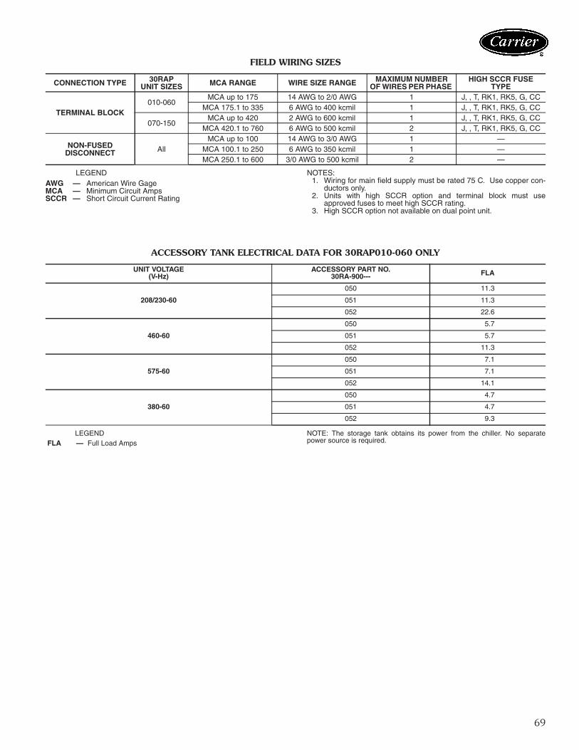
NOTE: When the accessory storage tank isemployed (sizes 010-060 only), the value fortotal weight increases (to be added to theweights shown above) by 1673 lb (759 kg)on 30RAP010-015, by 2193 lb (995 kg) on30RAP018-030, and by 4361 lb (1978 kg)on 30RAP035-060. Even with the storagetank, all 30RAP010-060 chillers require only4-point support.
30RAP100-150 UNITS
B
A
C D
CONTROLBOXSIDE
F E
a30-5439
12
Factory-installed optionsNovation® heat exchanger technology microchan-nel coil (aluminum fin/aluminum tube) e-coat con-denser is available for optimum durability. Novation heatexchangers with microchannel coil technology are offeredcoated or uncoated to match coil protection to site condi-tions. The Carrier Electronic Catalog (E-Cat) can be used todetermine whether or not corrosion protection is recom-mended for particular applications in coastal/marine envi-ronments. Following the input of the requested data, the E-Cat program output will advise the appropriate coil to beused. Other factors described in "Selection Guide: Environ-mental Corrosion Protection" catalog number04-581061-01 must also be considered to determine ifcorrosion protection is required.Value sound fans provide a metal, propeller-type fan sys-tem which is cost-effective when compared to the low-sound AeroAcoustic™ fan system. This factory-installed fanoption is compatible with the Motormaster® V option.Ultra-low sound provides a combination of low soundAeroAcoustic™ fans with sound blankets.Digital compressor control allows incremental unload-ing for a closer match to building load. This option is notavailable on sizes 100 - 150, or on any application with aleaving fluid temperature below 35 F (2 C).High short circuit current rating provides a short cir-cuit current rating protection for the unit up to 65,000 A
on 460-v, 380-v, and 208/230-v units or 25,000 A on575-v units. This is not available with dual point power.Motormaster® V low-ambient control provides con-trol of fan motor operation to maintain head pressure atlow outdoor ambient temperatures down to –20 F (–29 C)This option also requires field-installed wind baffles. Thisoption is also available as an accessory. This option is astandard feature on all 30RAP010 and 015 chillers.Non-fused disconnect includes factory-installed non-fused disconnect capability for power and control locatedat the unit. This is not available on dual point power at anysize, or on any 208/230-volt chiller in the 100-150 sizerange.Energy management module (EMM) provides energymanagement capabilities to minimize chiller energy con-sumption. Several features are provided with this moduleincluding leaving fluid temperature reset, cooling set pointreset or demand limit control from a 4 to 20 mA signal, 2-point demand limit control (from 0 to 100%) activated by aremote contact closure, and discrete input for “Ice Done”indication for ice storage system interface. The EMM isalso available as an accessory.Freeze protection with cooler heaters provides protec-tion from cooler freeze-up to –20 F (–29 C).GFI convenience outlet is a factory-installed conve-nience outlet that includes 4-amp GFI (ground faultinterrupter) receptacle with independent fuse protection.
ITEM FACTORY-INSTALLED OPTION FIELD-INSTALLED ACCESSORYCondenser Coil and Sound Options
MCHX E-Coat X Low Sound Compressor Blankets X
Value Sound Fans XUltra-Low Sound X
Controls/Communication OptionsBACnet Communication XBACnet Translator Control XChillervisor System Manager III Multi-Unit Control XEnergy Management Module (EMM) X XLON (Local Operating Network) Translator Control XNavigator™ Display XRemote Enhanced Display XTouch Pilot™ Display X
Cooler OptionsFreeze Protection — Cooler Heaters X
Remote Cooler Kit XElectrical Options
Unit-Mounted Main Disconnect, Non-Fused (not available with dual point power or 208/230 volt sizes 100-150) X
GFI Convenience Outlet (115 v) X X High SCCR (Short Circuit Current Rating) (not available with dual point power) X
Hydronics OptionHydronic Pump Package XChilled Water Storage Tank (available on sizes 010-060) XVariable Frequency Drive (VFD) (available on sizes 070-150) X
Refrigeration Circuit Options Compression Suction Service Valves (available on sizes 070-150) X
Low Ambient Temperature Head Pressure Control X XHot Gas Bypass (not available on sizes 010 and 015) X XDigital Compressor (available on sizes 010-090) X
Security/Packaging OptionsSecurity Grilles/Hail Guards X XVibration Isolation X
Wind Baffles X
Options and accessories
13
Convenience outlet is 115-v female receptacle. This optionis also available as an accessory.Compressor suction service valve provides additionalisolation of the compressor from the cooler vessel for ser-vice. This option is only available on sizes 070-150.Hydronic pump package option adds circulatingpumps, complete with controls, contactor, VFD compati-ble motors, and insulated expansion tank (expansion tankavailable on sizes 010-060 only). Available in single or dual(lead/lag controlled) cooler pump versions, with totaldynamic head external to the chiller from approximately15 to 160 ft (4.6 to 48.8 m). A VFD option is available onsizes 070-150.Hot gas bypass option allows additional capacity reduc-tion for unit operation down below the minimum standardstep of capacity. This option is not available on units withthe digital compressor option, on sizes 010 and 015 units,or any application with a leaving fluid temperature below35 F (2 C). This option is also available as an accessory onall 30RAP units without digital compressors.Security grilles/hail guards consist of louvered, sheetmetal panels which securely fasten to the chiller and pro-vide condenser coil protection against hail and physicaldamage. This option directly covers the coil(s) on sizes010-060. On sizes 070 and larger, the louvered panels areonly on the ends of the chiller, with a wire guard entirelycovering the sides of the chiller. This option is also avail-able as an accessory.BACnet communication option — Provides factory-installed communication capability with a BACnet MS/TPnetwork. Allows integration with i-Vu® Open control sys-tem or a BACnet building automation system.
Field-installed accessoriesBACnet translator control provides an interface be-tween the unit and a BACnet Local Area Network (LAN,i.e., MS/TP EIA-485). Field programming is required.Chillervisor System Manager III multi-unit controlaccessory allows sequencing of between two and eightchillers in parallel. Pump control is also provided.Energy management module provides energy manage-ment capabilities to minimize chiller energy consumption.Several features are provided with this module includingleaving fluid temperature reset, cooling set point reset ordemand limit control from a 4 to 20 mA signal, 2-pointdemand limit control (from 0 to 100%) activated by aremote contact closure, and discrete input for “Ice Done”indication for ice storage system interface. The EMM isalso available as an option.LON (local operating network) translator controlprovides an interface between the unit and a local operat-ing network (i.e., LonWorks* FT-10A ANSI/EIA-709.1).Field programming is required.Navigator™ display module provides a portable, handheld display module for convenient access to unit status,operation, configuration and troubleshooting diagnosticscapability. The 4-line, 80-character LCD (liquid crystaldisplay) display provides clear language information inEnglish, French, Spanish or Portuguese. The weatherproofenclosure and industrial grade extension cord make theNavigator module ideally suited for outdoor applications.Magnets located on the back of the module allow
attachment of any sheet metal component for hands freeoperation.Remote enhanced display accessory kit contains aremotely mounted 40-character per line, 16-line displaypanel for unit diagnostics.Touch Pilot™ display is a cost-effective, touch-screen,remote-mount device that can be used in lieu of the remoteenhanced display.Motormaster® V low-ambient control provides con-trol of outdoor-fan motor operation to maintain head pres-sure at low outdoor ambient temperatures down to –20 F(–29 C). This accessory also requires field-installed windbaffles. This accessory is also available as a factory-installedoption. This accessory is standard on 30RAP010 and 015units.Chilled water storage tank provides a minimum of4 gallons per ton loop storage capacity. Includes insulatedsteel shell tank, Victaulic pipe connections, electric tankheaters, electric cables, vent, drain, and enclosure to allowtank to be installed under the chiller to protect to –20 F(–29 C). The power supply for the storage tank is obtainedfrom the chiller, so no separate power source is requiredfor this accessory. This is available with sizes 010-060only.Vibration isolation consists of field-installed 1/4-in.(0.64 cm) neoprene isolator pads (24-in. x 3-in.) (61.0 cmx 7.6 cm) that reduce vibration transmission from the com-pressor through the floor and into the conditioned space.Low sound compressor blankets reduce unit soundlevels by providing an acoustic blanket on each compres-sor.Hot gas bypass accessory allows additional capacity re-duction for unit operation below the minimum standardstep of capacity. This accessory is not available on unitswhich have the digital compressor option or any applica-tion with a leaving fluid temperature below 35 F (2 C).This field-installed accessory is also available as afactory-installed option, but the factory option is notavailable with digital compressors or unit sizes 010 or 015.Remote cooler kit provides the additional hardware re-quired to remotely mount the cooler from the unit. Thereare limits to total separation of the unit to the cooler as wellas vertical separation limits, and these are delineated in theaccessory installation instructions. Never bury refrigerantpiping on these or any other applications.GFI convenience outlet is a field-installed convenienceoutlet that includes a 4-amp GFI (ground fault interrupter)receptacle with independent fuse protection. The conve-nience outlet is a 115-v female receptacle. The GFI conve-nience outlet is also available as a factory-installed option.Security grilles/hail guards consist of louvered, sheetmetal panels which securely fasten to the chiller and pro-vide condenser coil protection against hail and physicaldamage. This accessory directly covers the coil(s) on sizes010-060. On sizes 070 and larger, the louvered panels areonly on the ends of the chiller, with a wire guard entirelycovering the sides of the chiller. Security grilles/hail guardsare also available as a factory-installed option.Wind baffles facilitate operation down to –20 F (–29 C)when used in conjunction with low ambient temperaturehead pressure control.
*Registered trademark of Echelon Corporation.
14
9.
DIM
EN
SIO
NS
AR
E IN
INC
HE
S.
DIM
EN
SIO
NS
IN [
] AR
E IN
MIL
LIM
ETE
RS
.
a30-5578
Base unit dimensions — 30RAP010,015
15
9.
DIM
EN
SIO
NS
AR
E IN
INC
HE
S.
DIM
EN
SIO
NS
IN [
] AR
E IN
MIL
LIM
ET
ER
S.
a30-5579
Base unit dimensions — 30RAP018-030
16
9.
DIM
EN
SIO
NS
AR
E IN
INC
HE
S.
DIM
EN
SIO
NS
IN [
] AR
E IN
MIL
LIM
ET
ER
S.
a30-5580
Base unit dimensions — 30RAP035-060
17
a30-5881
Base unit dimensions — 30RAP070-090
18
a30-5882
Base unit dimensions — 30RAP100,115
19
a30-5583
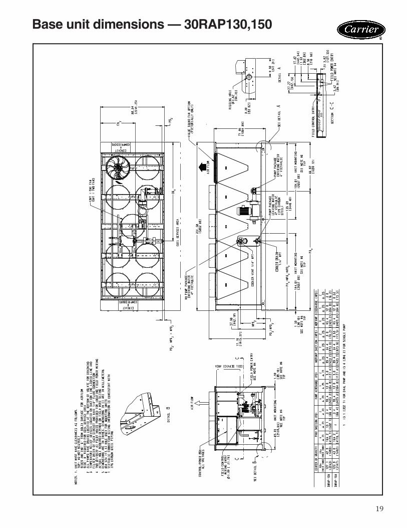
Base unit dimensions — 30RAP130,150
20
SE
E D
ETA
IL A
Ø2-
1/2
IN. V
ICTA
ULI
C W
ATE
RIN
LET/
OU
TLE
TA
CH
ILLE
R M
OU
NTI
NG
SLO
T
TAN
KA
CC
ES
S
TAN
KA
CC
ES
S
TAN
KA
CC
ES
S
TAN
KA
CC
ES
S
CH
ILLE
R W
ATE
R IN
(RE
F)
TAN
K A
CC
ES
S2'
8-1
3/32
"[8
23]
2' 4
7/64
"[6
28]
9-25
/32"
[248
]5-
3/4"
[146
]
5' 6
-15/
16"
[170
0]
TAN
K A
CC
ES
S
CH
ILLE
R W
ATE
R O
UT
(RE
F)
CO
NTR
OL
BO
X E
ND
1' 1
0-7/
8"[5
81]
2 X
12.
03[3
05.6
4]S
EC
TIO
N A
-A2
PLC
S
2 X
12.
03[3
05.6
6]
2 X
7.0
3[1
78.6
8]
2 X
14.
07[3
57.2
5]
1/4"
VE
NT
2 P
LCS
2" S
Q D
RA
IN2
PLC
S
3" [7
6.2]
MO
UN
TIN
G H
OLE
S,
FOU
R C
OR
NE
RS
(TY
P)
Ø .3
95/.4
05 (T
YP
)M
OU
NTI
NG
HO
LES
MID
DLE
EA
CH
SID
E2'
9-1
5/32
" [85
0]C
EN
TER
OF
GR
AVIT
Y
A1'
5-1
3/32
"[4
42]
Ø2-
1/2"
VIC
TAU
LIC
WAT
ER
INLE
T/O
UTL
ET
2 X
4-7
/8"
[124
]
2 X
1-1
/16"
[27]
1' 1
/32"
[306
]1' 1
/32"
[306
]
1' 5
-13/
32"
[442
]
1' 1
1-1/
2" [5
97]
CE
NTE
R O
F G
RAV
ITY
DE
TAIL
AAT
(4) P
LCS
Ø7/
16" [
11] X
1" [
25] L
G S
LOT
2 X
1" [
25]
CO
NTR
OL
BO
X E
ND
.88"
[22.
35]Ø
KN
OC
KO
UT
FOR
PO
WE
R T
O C
ON
TRO
L B
OX
TAN
KA
CC
ES
STA
NK
AC
CE
SS
TAN
KA
CC
ES
S
2 X
3' 1
-1/4
" [94
6]C
HIL
LER
MO
UN
TIN
G S
LOT
C.B
.A
CC
ES
S3'
10-
63/6
4"[1
193]
1-1/
2"[3
8.1]
AC
CESSO
RY
STO
RA
GE T
AN
K F
OR
UN
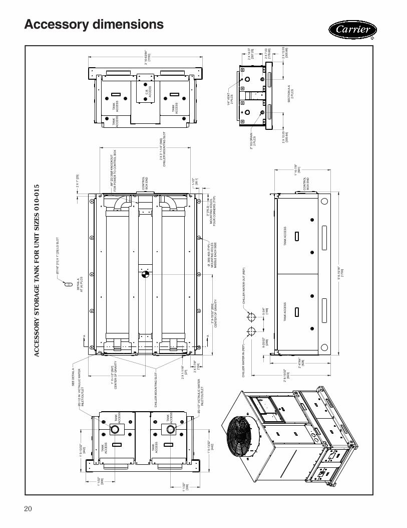
IT S
IZES 0
10-0
15
a30-5429
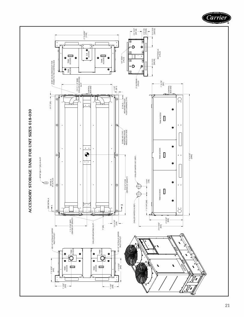
Accessory dimensions
21
AC
CESSO
RY
STO
RA
GE T
AN
K F
OR
UN
IT S
IZES 0
18-0
30
a30-5430
1' 5
-13/
32"
[442
]
1' 1
/32"
[305
]TA
NK
AC
CE
SS
TAN
KA
CC
ES
S
TAN
KA
CC
ES
S
TAN
KA
CC
ES
S
1' 1
/32"
[306
]
1' 5
-13/
32"
[442
]
Ø2-
1/2"
VIC
TAU
LIC
WAT
ER
INLE
T/O
UTL
ET
SE
E D
ETA
IL A
A
1' 1
1-17
/32"
[597
]C
EN
TER
OF
GR
AVIT
Y
CH
ILLE
R M
OU
NTI
NG
SLO
T
1" [2
6] 2 X
4-7
/8"
[124
]Ø
2-1/
2" V
ICTA
ULI
C W
ATE
RIN
LET/
OU
TLE
T
CH
ILLE
R W
ATE
R IN
(RE
F)
1' 3
-7/1
6" [3
92]
2' 8
-13/
32"
[823
]
2' 2
3/32
"[6
28]
7' 4
-31/
32"
[226
0]
TAN
K A
CC
ES
STA
NK
AC
CE
SS
5-3/
4"[1
46]
CH
ILLE
R W
ATE
R O
UT
(RE
F)
3' 8
-1/2
" [11
30]
CE
NTE
R O
F G
RAV
ITY
DE
TAIL
AAT
(4) P
LCSØ
7/32
" [6]
X 1
" [25
] LG
SLO
T
2 X
1" [
25]
Ø.8
8" (2
2.35
) KN
OC
KO
UT
FOR
PO
WE
R T
O T
HE
CO
NTR
OL
BO
X
TAN
KA
CC
ES
STA
NK
AC
CE
SS
2 X
3' 1
-1/4
" [94
6]C
HIL
LER
MO
UN
TIN
GS
LOT
CO
NTR
OL
BO
X E
ND
TAN
KA
CC
ES
S
Ø.3
95/.4
05 (T
YP
)M
OU
NTI
NG
HO
LES
,M
IDD
LE E
AC
H S
IDE
3" [7
6.2]
MO
UN
TIN
G H
OLE
SFO
UR
CO
RN
ER
S (T
YP
)
1-1/
2"[3
8.1] 2" S
Q D
RA
IN2
PLC
S
TAN
K A
CC
ES
S
CO
NTR
OL
BO
X E
ND1'
10-
7/8"
[581
]
SE
CTI
ON
A-A
2 P
LCS
2 X
12.
2[3
05.2
4]2
X 1
2.03
[305
.52]
2 X
7.0
3[1
78.6
8]
2 X
14.
07[3
57.2
5]
1/4"
VE
NT
2 P
LCS
3' 1
0-63
/64"
[119
3]C
.B.
AC
CE
SS
22
1' [3
05]
1' 5
-13/
32"
[442
]
TAN
KA
CC
ES
S
TAN
KA
CC
ES
S
TAN
KA
CC
ES
S1'
1/1
6"[3
06]
1' 5
-13/
32"
[442
]
CH
ILLE
R M
OU
NTI
NG
SLO
T
Ø2-
1/2"
VIC
TAU
LIC
WAT
ER
INLE
T/O
UTL
ET
DE
TAIL
AAT
(4) P
LCSØ
7/32
" [6]
X 1
" [25
] LG
SLO
T
SE
E D
ETA
IL A
1-1/
2"[3
8.1]
3" [7
6.2]
MO
UN
TIN
G H
OLE
S,
FOU
R C
OR
NE
RS
(TY
P)
A
4' 1
-3/8
" [12
54]
CE
NTE
R O
F G
RAV
ITY
3' 7
-31/
32"
[111
7]
MO
UN
TIN
G H
OLE
S 3' 7
-31/
32"
[111
7]
A
3' 8
-1/2
" [11
30]
CE
NTE
R O
F G
RAV
ITY
3' 8
-3/3
2" [1
120]
4' 6
-5/8
"[1
387]
2' 1
0-3/
32"
[866
]
2' 4
7/64
"[6
28]
TAN
KA
CC
ES
STA
NK
AC
CE
SS
TAN
KA
CC
ES
S
CO
NTR
OL
BO
X E
ND1'
10-
7/8"
[581
]
7' 4
-31/
32"
[226
0]
CH
ILLE
R W
ATE
R O
UT
FAR
SID
E (R
EF)
2 X
12.
02[3
05.2
3]2
X 2
2.94
[582
.56]
2" S
Q D
RA
IN4
PLC
S
CH
ILLE
R W
ATE
R IN
FAR
SID
E (R
EG
)
2 X
0' -
1 1/
6"2
X 0
' -4
7/8"
2 X
28.
84[7
32.4
3]
SE
CTI
ON
A-A
2 P
LCS
CO
NTR
OL
BO
X E
ND
MO
UN
TIN
G H
OLE
S
Ø.8
8" (2
2.35
) KN
OC
KO
UT
FOR
PO
WE
R T
O T
HE
CO
NTR
OL
BO
X
2 X
7' 5
" [22
60]
CH
ILLE
R M
OU
NTI
NG
SLO
T
TAN
KA
CC
ES
S
CO
NTR
OL
BO
X E
ND
Ø.8
8" (2
2.35
) KN
OC
KO
UT
FOR
PO
WE
R T
O T
HE
CO
NTR
OL
BO
X
TAN
KA
CC
ES
S
Ø.3
95/.4
05 (T
YP
)M
OU
NTI
NG
HO
LES
,M
IDD
LE E
AC
H S
IDE
TAN
KAC
CES
S
8' 2
-3/4
"[2
508]
1/4"
VE
NT
4 P
LCS
2 X
22.
90[5
81.6
5]2
X 1
2.06
[306
.43]
4 X
14.
07[3
57.2
5]
4 X
7.0
3[1
78.6
8]
TAN
KAC
CES
S
TAN
KAC
CES
S
TAN
KAC
CES
SC.B
.AC
CES
S
C.B
.AC
CES
S
AC
CESSO
RY
STO
RA
GE T
AN
K F
OR
UN
IT S
IZES 0
35-0
60
a30-5431
Accessory dimenions (cont)
23
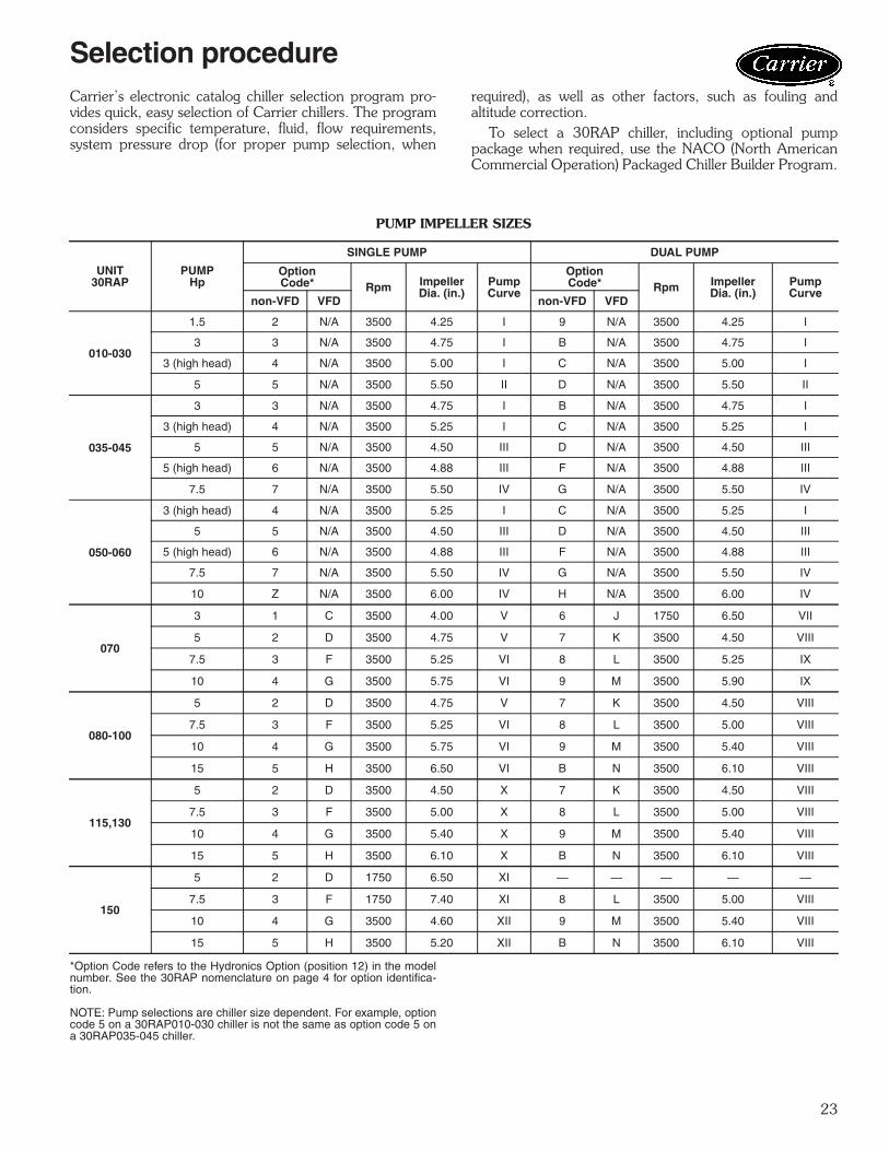
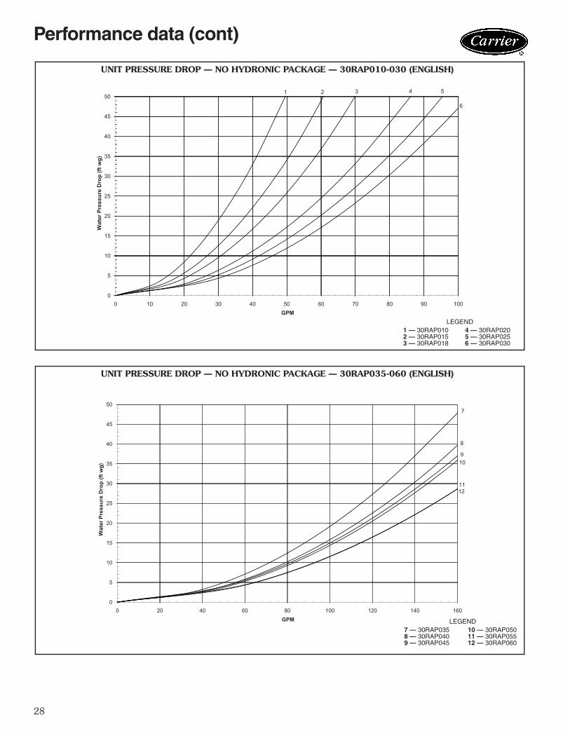
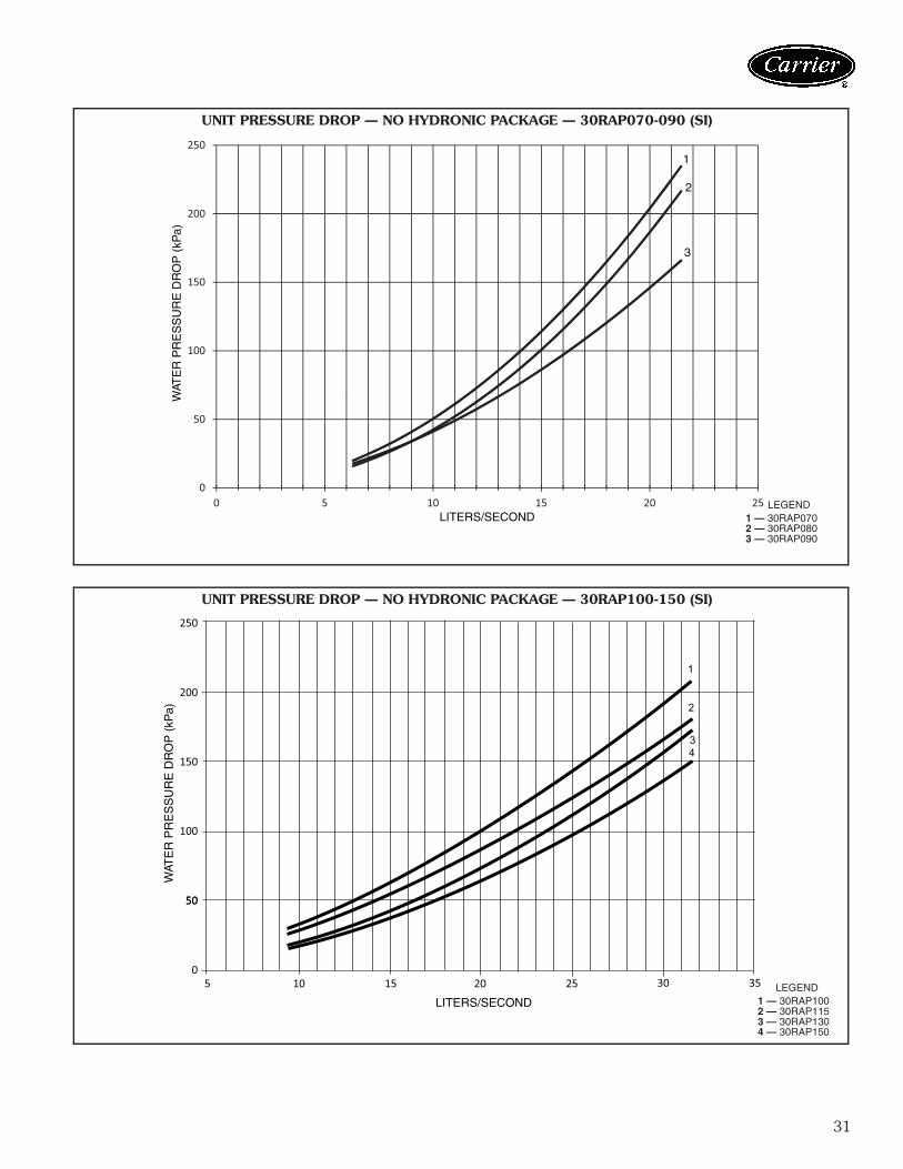
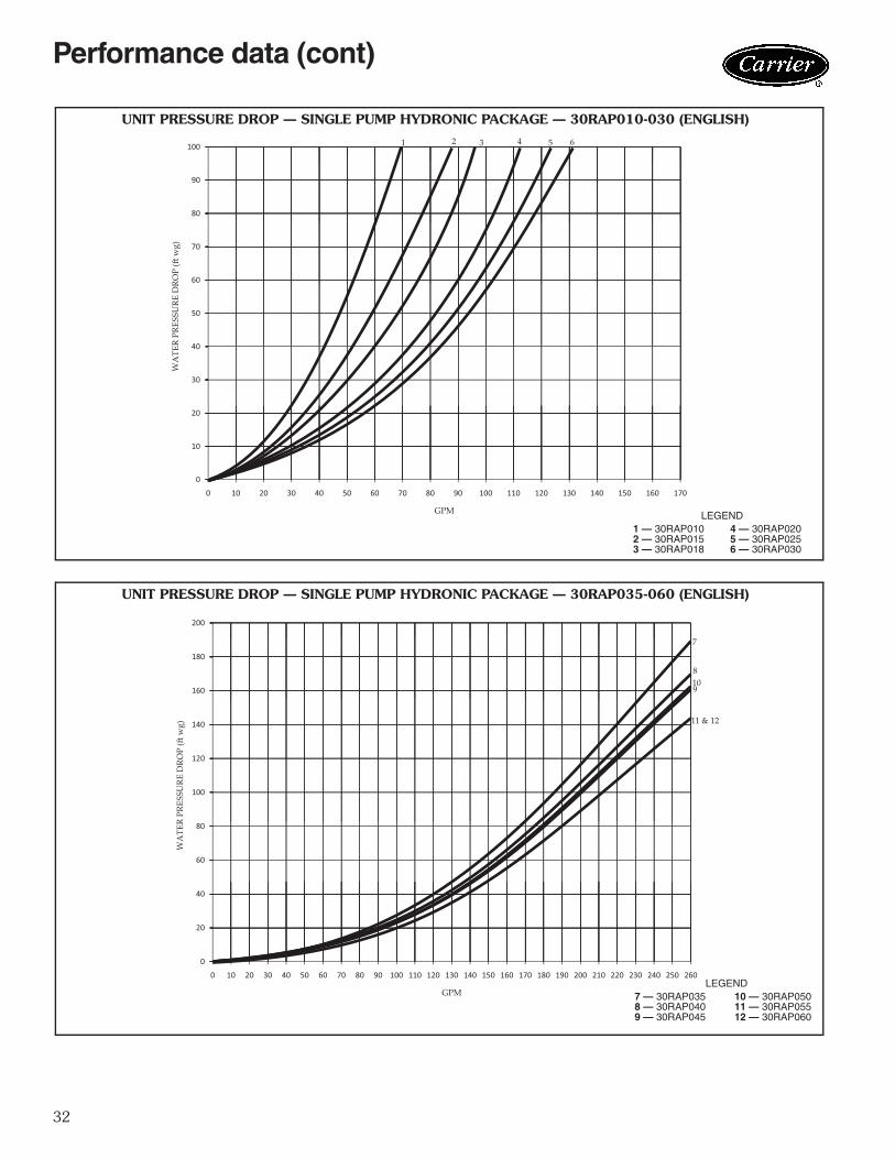
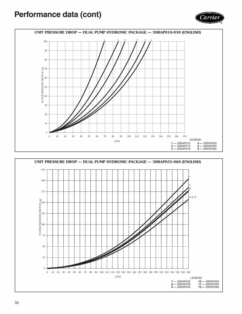
Carrier’s electronic catalog chiller selection program pro-vides quick, easy selection of Carrier chillers. The programconsiders specific temperature, fluid, flow requirements,system pressure drop (for proper pump selection, when
required), as well as other factors, such as fouling andaltitude correction.
To select a 30RAP chiller, including optional pumppackage when required, use the NACO (North AmericanCommercial Operation) Packaged Chiller Builder Program.
PUMP IMPELLER SIZES
*Option Code refers to the Hydronics Option (position 12) in the modelnumber. See the 30RAP nomenclature on page 4 for option identifica-tion.
NOTE: Pump selections are chiller size dependent. For example, optioncode 5 on a 30RAP010-030 chiller is not the same as option code 5 ona 30RAP035-045 chiller.
UNIT30RAP
PUMPHp
SINGLE PUMP DUAL PUMP
OptionCode* Rpm Impeller
Dia. (in.)PumpCurve
OptionCode* Rpm Impeller
Dia. (in.)PumpCurve
non-VFD VFD non-VFD VFD
010-030
1.5 2 N/A 3500 4.25 I 9 N/A 3500 4.25 I
3 3 N/A 3500 4.75 I B N/A 3500 4.75 I
3 (high head) 4 N/A 3500 5.00 I C N/A 3500 5.00 I
5 5 N/A 3500 5.50 II D N/A 3500 5.50 II
035-045
3 3 N/A 3500 4.75 I B N/A 3500 4.75 I
3 (high head) 4 N/A 3500 5.25 I C N/A 3500 5.25 I
5 5 N/A 3500 4.50 III D N/A 3500 4.50 III
5 (high head) 6 N/A 3500 4.88 III F N/A 3500 4.88 III
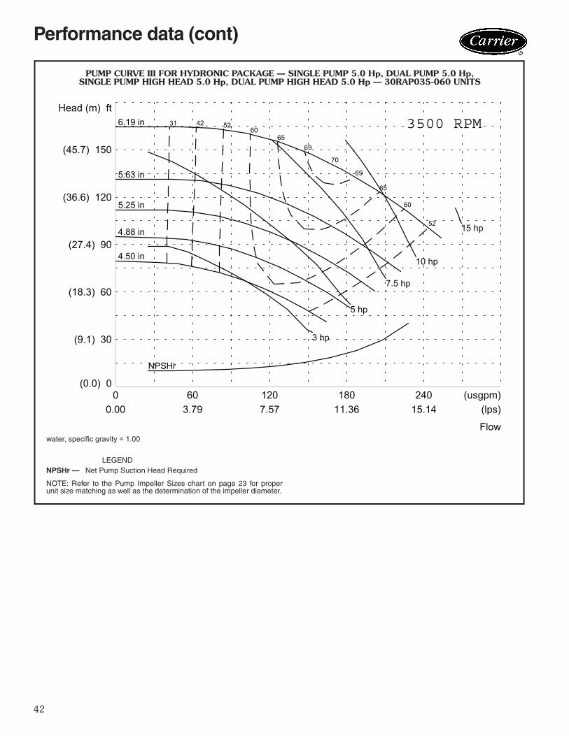
7.5 7 N/A 3500 5.50 IV G N/A 3500 5.50 IV
050-060
3 (high head) 4 N/A 3500 5.25 I C N/A 3500 5.25 I
5 5 N/A 3500 4.50 III D N/A 3500 4.50 III
5 (high head) 6 N/A 3500 4.88 III F N/A 3500 4.88 III
PUMP CURVE I FOR HYDRONIC PACKAGE — SINGLE PUMP 1.5 Hp, DUAL PUMP 1.5 Hp,SINGLE PUMP 3.0 Hp, DUAL PUMP 3.0 Hp, SINGLE PUMP HIGH HEAD 3.0 Hp,
DUAL PUMP HIGH HEAD 3.0 Hp — 30RAP010-060 UNITS
00.00
301.89
603.79
905.68
1207.57
(usgpm)(lps)
(0.0) 0
(6.1) 20
(12.2) 40
(18.3) 60
(24.4) 80
(30.5) 100
HEAD (m) ft
FLOW
3500 RPM
NPSHr
4.25 in
4.50 in
4.75 in
5.00 in
5555
53
53
51
51
48
48
4336
NPSHr 0.75 hp
1 hp
1.5 hp
2 hp
3 hp
5.25 in
4.00 in
54
LEGEND
NOTE: Refer to the Pump Impeller Sizes chart on page 23 for properunit size matching as well as the determination of the impeller diameter.
NPSHr — Net Pump Suction Head Required a30-5260
water, specific gravity = 1.00
Performance data (cont)
41
00.00
301.89
603.79
905.68
1207.57
1509.46
(usgpm)(lps)
(0.0) 0
(12.2) 40
(24.4) 80
(36.6) 120
(48.8) 160
(61.0) 200
HEAD (m) ft
FLOW
3500 RPM
NPSHr
6.50 in
6.00 in
5.50 in
54
54
51
51
47
47
41
41
35
35%
27
NPSHr2 hp
3 hp
5 hp
7.5 hp
10 hp
7.00 in
5.00 in
55
PUMP CURVE II FOR HYDRONIC PACKAGE — SINGLE PUMP 5.0 Hp,DUAL PUMP 5.0 Hp — 30RAP010-030 UNITS
LEGEND
NOTE: Refer to the Pump Impeller Sizes chart on page 23 for properunit size matching as well as the determination of the impeller diameter.
NPSHr — Net Pump Suction Head Requireda30-5261
water, specific gravity = 1.00
42
00.00
603.79
1207.57
18011.36
24015.14
(usgpm)(lps)
(0.0) 0
(9.1) 30
(18.3) 60
(27.4) 90
(36.6) 120
(45.7) 150
Head (m) ft
Flow
3500 RPM
4.88 in
5.25 in
5.63 in
69
69
65
65
60
60
52
52
4231
NPSHr
3 hp
5 hp
7.5 hp
10 hp
15 hp
6.19 in
4.50 in
70
LEGEND
NOTE: Refer to the Pump Impeller Sizes chart on page 23 for properunit size matching as well as the determination of the impeller diameter.
NPSHr — Net Pump Suction Head Required
PUMP CURVE III FOR HYDRONIC PACKAGE — SINGLE PUMP 5.0 Hp, DUAL PUMP 5.0 Hp,SINGLE PUMP HIGH HEAD 5.0 Hp, DUAL PUMP HIGH HEAD 5.0 Hp — 30RAP035-060 UNITS
a30-5262
water, specific gravity = 1.00
Performance data (cont)
43
00.00
603.79
1207.57
18011.36
24015.14
30018.93
(usgpm)(lps)
(0.0) 0
(12.2) 40
(24.4) 80
(36.6) 120
(48.8) 160
(61.0) 200
Head (m) ft
Flow
3500 RPM
NPSHr
6.50 in
6.00 in
5.50 in
61
61
58
58
55
55
49
49%
4233
NPSHr
3 hp
5 hp
7.5 hp
10 hp
15 hp
20 hp
7.00 in
5.00 in
61
PUMP CURVE IV FOR HYDRONIC PACKAGE — SINGLE PUMP 7.5 Hp, DUAL PUMP 7.5 Hp,SINGLE PUMP 10.0 Hp, DUAL PUMP 10.0 Hp — 30RAP035-060 UNITS
LEGEND
NOTE: Refer to the Pump Impeller Sizes chart on page 23 for properunit size matching as well as the determination of the impeller diameter.
NPSHr — Net Pump Suction Head Required a30-5263
water, specific gravity = 1.00
44
PUMP CURVE V FOR HYDRONIC PACKAGE — SINGLE PUMP 3 Hp, SINGLE PUMP 5 Hp — 30RAP070-100 UNITS
4.75 in.39 50
5966
71
74
75
74
71
66
59%
50% 3 hp
1 hp
3.21 in.
4.00 in.
5 hp
1.5 hp2 hp
3500 RPM
00.00
805.05
16010.09
24015.14
32020.19
40025.24
(usgpm)(lps)
Flow
(0.0) 0
(3.0) 10
(6.1) 20
(9.1) 30
(12.2) 40
(15.2) 50
Head (m) ft
(18.3) 60
(21.3) 70
NPSHr
3.63 in.
4.38 in.
39%
LEGEND
NOTE: Refer to the Pump Impeller Sizes chart on page 23 for properunit size matching as well as the determination of the impeller diameter.
NPSHr — Net Pump Suction Head Required
a30-5359water, specific gravity = 1.00
Performance data (cont)
45
00.00
805.05
16010.09
24015.14
32020.19
40025.24
(usgpm)(lps)
(0.0) 0
(9.1) 30
(18.3) 60
(27.4) 90
(36.6) 120
(45.7) 150
Head (m) ft
Flow
3500 RPM
NPSHr
6.13 in.
5.75 in.
5.38 in.
69
71
64
69
58
64
49
58%
39
NPSHr 3 hp
5 hp
7.5 hp
10 hp
15 hp
20 hp
6.50 in.
5.00 in.
71
72
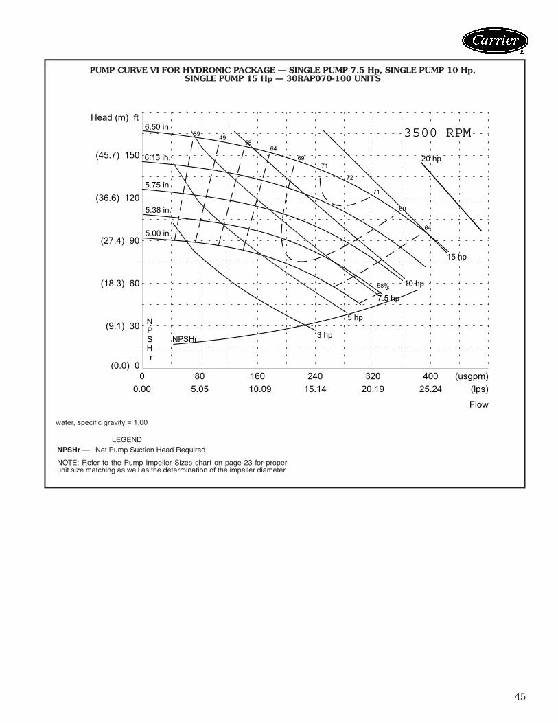
PUMP CURVE VI FOR HYDRONIC PACKAGE — SINGLE PUMP 7.5 Hp, SINGLE PUMP 10 Hp,SINGLE PUMP 15 Hp — 30RAP070-100 UNITS
LEGEND
NOTE: Refer to the Pump Impeller Sizes chart on page 23 for properunit size matching as well as the determination of the impeller diameter.
NPSHr — Net Pump Suction Head Required
a30-5358
water, specific gravity = 1.00
46
0
(0.00)
80
(5.05)
160
(10.09)
240
(15.14)
320
(20.19)
400
(25.24)
(gpm)
(l/s)us
(0.0) 0
(3.7) 12
(7.3) 24
(11.0) 36
(14.6) 48
(18.3) 60
Head Pressure (m) ft of fluid
Flow Rate
1750 RPM
NPSHr
6.50 in
7.30 in
8.15 in80
80
77
77
72
72
64
64
53
53
39
NPSHr1 hp
1.5 hp2 hp
3 hp
5 hp
7.5 hp
8.19 in
6.00 in
80
PUMP CURVE VII FOR HYDRONIC PACKAGE — DUAL PUMP 3 Hp — 30RAP070 UNITS
LEGEND
NOTE: Refer to the Pump Impeller Sizes chart on page 23 for properunit size matching as well as the determination of the impeller diameter.
NPSHr — Net Pump Suction Head Requireda30-4391
water, specific gravity = 1.00
Performance data (cont)
47
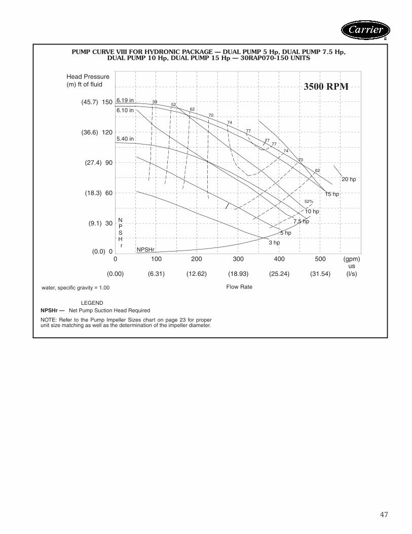
0
(0.00)
100
(6.31)
200
(12.62)
300
(18.93)
400
(25.24)
500
(31.54)
(gpm)
(l/s)us
(0.0) 0
(9.1) 30
(18.3) 60
(27.4) 90
(36.6) 120
(45.7) 150
Head Pressure (m) ft of fluid
Flow Rate
3500 RPM
NPSHr
77
77
74
74
70
70
62
62
52
52%
39
NPSHr3 hp
5 hp
7.5 hp
10 hp
15 hp
20 hp
6.19 in
6.10 in
5.40 in 77
PUMP CURVE VIII FOR HYDRONIC PACKAGE — DUAL PUMP 5 Hp, DUAL PUMP 7.5 Hp,DUAL PUMP 10 Hp, DUAL PUMP 15 Hp — 30RAP070-150 UNITS
a30-4393
LEGEND
NOTE: Refer to the Pump Impeller Sizes chart on page 23 for properunit size matching as well as the determination of the impeller diameter.
NPSHr — Net Pump Suction Head Required
water, specific gravity = 1.00
48
0
(0.00)
60
(3.79)
120
(7.57)
180
(11.36)
240
(15.14)
(gpm)
(l/s)us
(0.0) 0
(9.1) 30
(18.3) 60
(27.4) 90
(36.6) 120
(45.7) 150
Head Pressure(m) ft of fluid
Flow Rate
3500 RPM
NPSHr
5.90 in69
69
65
65
60
60
52
52
4231
NPSHr
3 hp
5 hp
7.5 hp
10 hp
15 hp
6.19 in
4.50 in
70
5.25 in
PUMP CURVE IX FOR HYDRONIC PACKAGE — DUAL PUMP 7.5 Hp,DUAL PUMP 10 Hp — 30RAP070 UNITS
a30-4392 LEGEND
NOTE: Refer to the Pump Impeller Sizes chart on page 23 for properunit size matching as well as the determination of the impeller diameter.
NPSHr — Net Pump Suction Head Required
water, specific gravity = 1.00
Performance data (cont)
49
00.00
503.15
1006.31
1509.46
20012.62
25015.77
(usgpm)(lps)
(0.0) 0
(12.2) 40
(24.4) 80
(36.6) 120
(48.8) 160
Head (m) ft
FlowWater, sg= 1.00
3500 RPM
NPSHr
6.19 in
4.50 in
5 hp
7.5 hp
10 hp
15 hp
3 hp
65
65
62
62
56
56
49
49
4029
4.88 in
5.25 in
5.63 in
NPSHr
66
PUMP CURVE X FOR HYDRONIC PACKAGE — SINGLE PUMP 5 HP, SINGLE PUMP 7.5 HP, SINGLE PUMP 10 HP, SINGLE PUMP 15 HP — 30RAP115,130 UNITS
a30-5450
LEGEND
NOTE: Refer to the Pump Impeller Sizes chart on page 23 for properunit size matching as well as the determination of the impeller diameter.
NPSHr — Net Pump Suction Head Required
water, specific gravity = 1.00
50
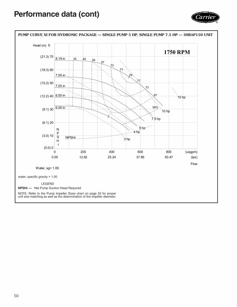
00.00
20012.62
40025.24
60037.85
80050.47
(usgpm)(lps)
(0.0) 0
(3.0) 10
(6.1) 20
(9.1) 30
(12.2) 40
(15.2) 50
(18.3) 60
(21.3) 70
Head (m) ft
FlowWater, sg= 1.00
1750 RPM
NPSHr
8.19 in
6.00 in
4 hp5 hp
7.5 hp
10 hp
15 hp
3 hp
77
77
73
73
67
67
59
59%
4835
6.50 in
7.00 in
7.50 in
NPSHr
78
PUMP CURVE XI FOR HYDRONIC PACKAGE — SINGLE PUMP 5 HP, SINGLE PUMP 7.5 HP — 30RAP150 UNIT
a30-5451 LEGEND
NOTE: Refer to the Pump Impeller Sizes chart on page 23 for properunit size matching as well as the determination of the impeller diameter.
NPSHr — Net Pump Suction Head Required
water, specific gravity = 1.00
Performance data (cont)
51
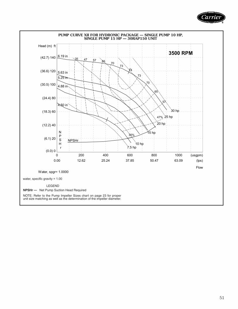
00.00
20012.62
40025.24
60037.85
80050.47
100063.09
(usgpm)(lps)
(0.0) 0
(6.1) 20
(12.2) 40
(18.3) 60
(24.4) 80
(30.5) 100
(36.6) 120
(42.7) 140
Head (m) ft
6.19 in
4.50 in
10 hp
15 hp
20 hp
25 hp
30 hp
7.5 hp
73
73
70
70
65
65
57
57
47
47%
35
35%
4.88 in
5.25 in 5.63 in
NPSHr
FlowWater, spgr= 1.0000
3500 RPM
NPSHr
74
PUMP CURVE XII FOR HYDRONIC PACKAGE — SINGLE PUMP 10 HP, SINGLE PUMP 15 HP — 30RAP150 UNIT
a30-5452 LEGEND
NOTE: Refer to the Pump Impeller Sizes chart on page 23 for properunit size matching as well as the determination of the impeller diameter.
NPSHr — Net Pump Suction Head Required
water, specific gravity = 1.00
52
STORAGE TANK PRESSURE DROP CURVES
1ACCESSORY TANK FLOW RATE (gpm)
PR
ES
SU
RE
DR
OP
(ft
wg)
30RAP035-060
30RAP010-030
100.0
10.0
1.0
0.110 100 1000
a30-4882
0.1
1.0
10.0
1.0 10.0ACCESSORY TANK FLOW RATE (L/s)
PR
ES
SU
RE
DR
OP
(kP
a)
30RAP035-060
30RAP010-030
100.0
a30-4883
Performance data (cont)
53
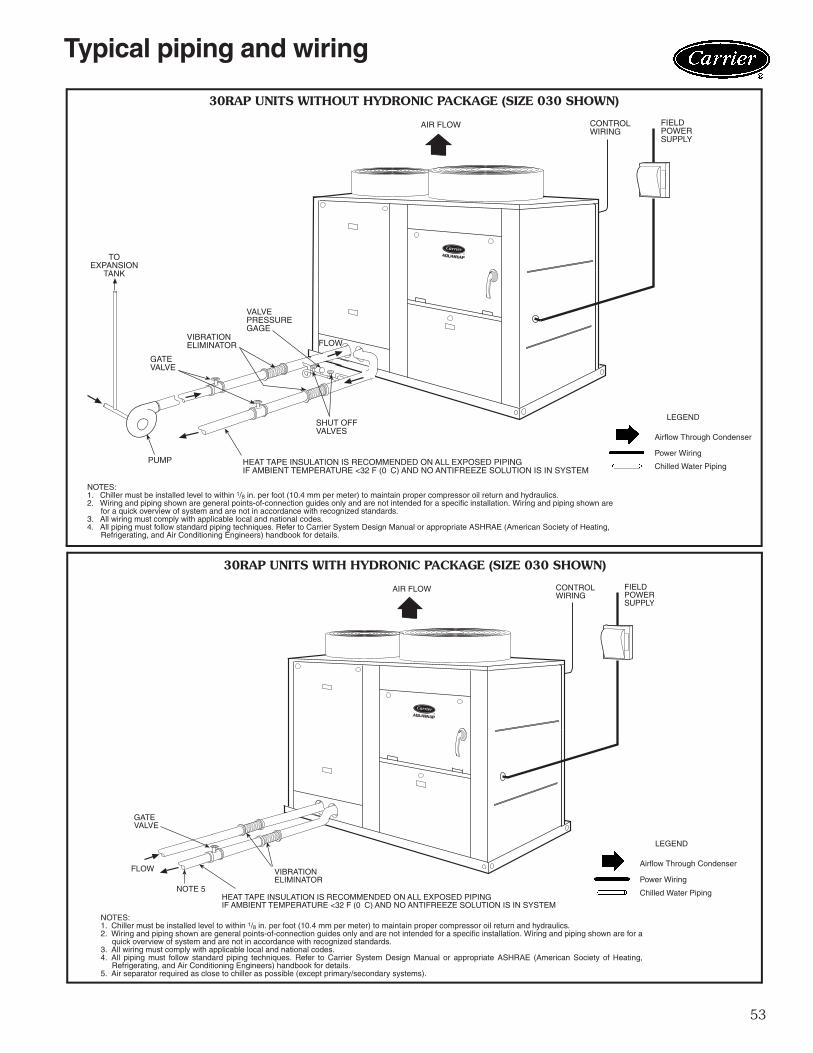
AIR FLOW FIELDPOWERSUPPLY
CONTROLWIRING
FLOW
GATEVALVE
VIBRATIONELIMINATOR
VALVEPRESSUREGAGE
SHUT OFFVALVES
HEAT TAPE INSULATION IS RECOMMENDED ON ALL EXPOSED PIPINGIF AMBIENT TEMPERATURE <32 F (0 C) AND NO ANTIFREEZE SOLUTION IS IN SYSTEM
TOEXPANSION
TANK
PUMP
AIR FLOW FIELDPOWERSUPPLY
CONTROLWIRING
FLOW
GATEVALVE
VIBRATIONELIMINATOR
NOTE 5HEAT TAPE INSULATION IS RECOMMENDED ON ALL EXPOSED PIPINGIF AMBIENT TEMPERATURE <32 F (0 C) AND NO ANTIFREEZE SOLUTION IS IN SYSTEM
30RAP UNITS WITHOUT HYDRONIC PACKAGE (SIZE 030 SHOWN)
30RAP UNITS WITH HYDRONIC PACKAGE (SIZE 030 SHOWN)
NOTES:1. Chiller must be installed level to within 1/8 in. per foot (10.4 mm per meter) to maintain proper compressor oil return and hydraulics.2. Wiring and piping shown are general points-of-connection guides only and are not intended for a specific installation. Wiring and piping shown are
for a quick overview of system and are not in accordance with recognized standards.3. All wiring must comply with applicable local and national codes.4. All piping must follow standard piping techniques. Refer to Carrier System Design Manual or appropriate ASHRAE (American Society of Heating,
Refrigerating, and Air Conditioning Engineers) handbook for details.
LEGEND
Airflow Through Condenser
Power Wiring
Chilled Water Piping
LEGEND
Airflow Through Condenser
Power Wiring
Chilled Water Piping
NOTES:1. Chiller must be installed level to within 1/8 in. per foot (10.4 mm per meter) to maintain proper compressor oil return and hydraulics.2. Wiring and piping shown are general points-of-connection guides only and are not intended for a specific installation. Wiring and piping shown are for a
quick overview of system and are not in accordance with recognized standards.3. All wiring must comply with applicable local and national codes.4. All piping must follow standard piping techniques. Refer to Carrier System Design Manual or appropriate ASHRAE (American Society of Heating,
Refrigerating, and Air Conditioning Engineers) handbook for details.5. Air separator required as close to chiller as possible (except primary/secondary systems).
a30-4867
a30-4868
Typical piping and wiring
54
FLOWGATEVALVE
VIBRATIONELIMINATOR
TOEXPANSION
TANK
PUMP
HEAT TAPE INSULATION IS RECOMMENDED ON ALL EXPOSED PIPINGIF AMBIENT TEMPERATURE <32 F (0 C) AND NO ANTIFREEZE SOLUTION IS IN SYSTEM
FLOW
GATEVALVE
VIBRATIONELIMINATOR
VALVEPRESSUREGAGE
SHUT OFFVALVES
FIELDPOWERSUPPLY
GATEVALVE
VIBRATIONELIMINATOR
NOTE 5HEAT TAPE INSULATION IS RECOMMENDED ON ALL EXPOSED PIPINGIF AMBIENT TEMPERATURE <32 F (0 C) AND NO ANTIFREEZE SOLUTION IS IN SYSTEM
FLOW
VIBRATIONELIMINATOR
FIELDPOWERSUPPLY
30RAP UNITS WITHOUT HYDRONIC PACKAGE (SIZE 060 SHOWN)
30RAP UNITS WITH HYDRONIC PACKAGE (SIZE 060 SHOWN)
NOTES:1. Chiller must be installed level to within 1/8 in. per foot (10.4 mm per meter) to maintain proper compressor oil return and hydraulics.2. Wiring and piping shown are general points-of-connection guides only and are not intended for a specific installation. Wiring and piping shown are
for a quick overview of system and are not in accordance with recognized standards.3. All wiring must comply with applicable local and national codes.4. All piping must follow standard piping techniques. Refer to Carrier System Design Manual or appropriate ASHRAE (American Society of Heating,
Refrigerating, and Air Conditioning Engineers) handbook for details.
LEGEND
Airflow Through Condenser
Power Wiring
Chilled Water Piping
LEGEND
Airflow Through Condenser
Power Wiring
Chilled Water PipingNOTES:1. Chiller must be installed level to within 1/8 in. per foot (10.4 mm per meter) to maintain proper compressor oil return and hydraulics.2. Wiring and piping shown are general points-of-connection guides only and are not intended for a specific installation. Wiring and piping shown are for a
quick overview of system and are not in accordance with recognized standards.3. All wiring must comply with applicable local and national codes.4. All piping must follow standard piping techniques. Refer to Carrier System Design Manual or appropriate ASHRAE (American Society of Heating,
Refrigerating, and Air Conditioning Engineers) handbook for details.5. Air separator required as close to chiller as possible (except primary/secondary systems).
a30-4869
a30-4870
Typical piping and wiring (cont)
55
FIELDPOWERSUPPLY
CONTROLWIRING
AIR FLOW
FLOWVIBRATORELIMINATOR
GATE VALVE
HEAT TAPE INSULATION RECOMMENDED ON ALL EXPOSED PIPINGIF AMBIENT TEMPERATURE <32 F (0 C) AND NO ANTIFREEZE SOLUTION IS IN SYSTEM
NOTES:1. Chiller must be installed level to within 1/8 in. per foot (10.4 mm per meter) to maintain proper compressor oil return and hydraulics.2. Wiring and piping shown are general points-of-connection guides only and are not intended for a specific installation. Wiring and piping
shown are for a quick overview of system and are not in accordance with recognized standards.3. All wiring must comply with applicable local and national codes.4. All piping must follow standard piping techniques. Refer to Carrier System Design Manual or appropriate ASHRAE (American Society of
Heating, Refrigerating, and Air Conditioning Engineers) handbook for details.
LEGEND
Airflow Through Condenser
Power Wiring
Chilled Water Piping
LEGEND
Airflow Through Condenser
Power Wiring
Chilled Water Piping
NOTES:1. Chiller must be installed level to within 1/8 in. per foot (10.4 mm per meter) to maintain proper compressor oil return and hydraulics.2. Wiring and piping shown are general points-of-connection guides only and are not intended for a specific installation. Wiring and piping
shown are for a quick overview of system and are not in accordance with recognized standards.3. All wiring must comply with applicable local and national codes.4. All piping must follow standard piping techniques. Refer to Carrier System Design Manual or appropriate ASHRAE (American Society of
Heating, Refrigerating, and Air Conditioning Engineers) handbook for details.5. Air separator required as close to chiller as possible (except primary/secondary systems).
30RAP UNITS WITH HYDRONIC PACKAGE FOR SIZES 070 AND LARGER (SIZE 070-090 SHOWN)
FIELDPOWERSUPPLY
CONTROLWIRING
AIR FLOW
TOEXPANSION
TANKVALVE PRESSURE
GAGEGATEVALVE
PUMPVIBRATOR ELIMINATOR SHUT OFF
VALVES HEAT TAPE INSULATION RECOMMENDED ON ALL EXPOSED PIPINGIN AMBIENT TEMPERATURE <32 F (0 C) AND NO ANTIFREEZE SOLUTION IS IN SYSTEM
30RAP UNITS WITHOUT HYDRONIC PACKAGE FOR SIZES 070 AND LARGER (SIZE 070-090 SHOWN)
56
89
10
12 11
14
12 11
13
2
1
3
4
5 6
7
6
TYPICAL PIPING DIAGRAM ON 30RAP UNITS WITH HYDRONIC PACKAGE
LEGEND
1 — Strainer/Blow-Down Valve2 — Expansion Tank (sizes 010 - 060 only)3 — Pump4 — Electric Heater5 — Air Vent Connection Port6 — Pressure/Temperature Access Port7 — Heat Exchanger
Electrical data30RAP ELECTRICAL DATA — SINGLE POINT NO HYDRONIC PACKAGE
LEGEND
NOTES:1. Units are suitable for use on electrical systems where voltage supplied to the
unit terminals is not below or above the listed minimum and maximum limits.Maximum allowable phase imbalance is: voltage, 2%; amps 10%.
2. All units/modules have single point primary power connection. (Each unit/module requires its own power supply.) Main power must be supplied from afield-supplied disconnect.
3. Cooler heater is wired into the control circuit so it is always operable as longas the power supply disconnect and heater safety device are on.
4. Power draw control circuits include both crankcase heaters (sizes 070-150only) and cooler heaters (where used). Each compressor on sizes 070-090has a crankcase heater which draws 90 watts of power, while each compres-sor on sizes 100-150 has a crankcase heater which draws 56 watts of power.
UNIT30RAP
UNIT VOLTAGE POWERSUPPLY
QTYREQD.
NO HYDRONIC PACKAGESTANDARD LOW-SOUND AEROACOUSTIC™ FAN
ICF — Instantaneous Current FlowMCA — Minimum Circuit AmpsMOCP — Maximum Overcurrent Protection
58
30RAP ELECTRICAL DATA (cont)DUAL POINT LOW SOUND AEROACOUSTIC™ FAN NO HYDRONIC PACKAGE
DUAL POINT OPTIONAL VALUE SOUND FAN NO HYDRONIC PACKAGE
LEGEND
NOTES:1. Units are suitable for use on electrical systems where voltage supplied to the
unit terminals is not below or above the listed minimum and maximum limits.Maximum allowable phase imbalance is: voltage, 2%; amps 10%.
2. All units/modules have dual point primary power connection. (Each unit/mod-ule requires its own power supply.) Main power must be supplied from a field-supplied disconnect.
3. Cooler heater is wired into the control circuit so it is always operable as longas the power supply disconnect and heater safety device are on.
4. Power draw control circuits include both crankcase heaters (sizes 070-150only) and cooler heaters (where used). Each compressor on sizes 070-090has a crankcase heater which draws 90 watts of power, while each compres-sor on sizes 100-150 has a crankcase heater which draws 56 watts of power.
ICF — Instantaneous Current FlowMCA — Minimum Circuit AmpsMOCP — Maximum Overcurrent Protection
Electrical data (cont)
59
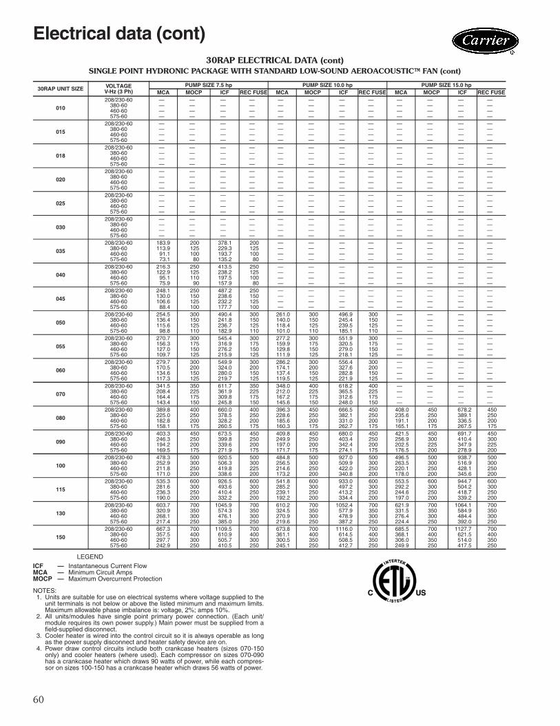
30RAP ELECTRICAL DATA (cont)SINGLE POINT HYDRONIC PACKAGE WITH STANDARD LOW-SOUND AEROACOUSTIC™ FAN
LEGEND
NOTES:1. Units are suitable for use on electrical systems where voltage supplied to the
unit terminals is not below or above the listed minimum and maximum limits.Maximum allowable phase imbalance is: voltage, 2%; amps 10%.
2. All units/modules have single point primary power connection. (Each unit/module requires its own power supply.) Main power must be supplied from afield-supplied disconnect.
3. Cooler heater is wired into the control circuit so it is always operable as longas the power supply disconnect and heater safety device are on.
4. Power draw control circuits include both crankcase heaters (sizes 070-150only) and cooler heaters (where used). Each compressor on sizes 070-090has a crankcase heater which draws 90 watts of power, while each compres-sor on sizes 100-150 has a crankcase heater which draws 56 watts of power.
ICF — Instantaneous Current FlowMCA — Minimum Circuit AmpsMOCP — Maximum Overcurrent Protection
60
30RAP ELECTRICAL DATA (cont)SINGLE POINT HYDRONIC PACKAGE WITH STANDARD LOW-SOUND AEROACOUSTIC™ FAN (cont)
LEGEND
NOTES:1. Units are suitable for use on electrical systems where voltage supplied to the
unit terminals is not below or above the listed minimum and maximum limits.Maximum allowable phase imbalance is: voltage, 2%; amps 10%.
2. All units/modules have single point primary power connection. (Each unit/module requires its own power supply.) Main power must be supplied from afield-supplied disconnect.
3. Cooler heater is wired into the control circuit so it is always operable as longas the power supply disconnect and heater safety device are on.
4. Power draw control circuits include both crankcase heaters (sizes 070-150only) and cooler heaters (where used). Each compressor on sizes 070-090has a crankcase heater which draws 90 watts of power, while each compres-sor on sizes 100-150 has a crankcase heater which draws 56 watts of power.
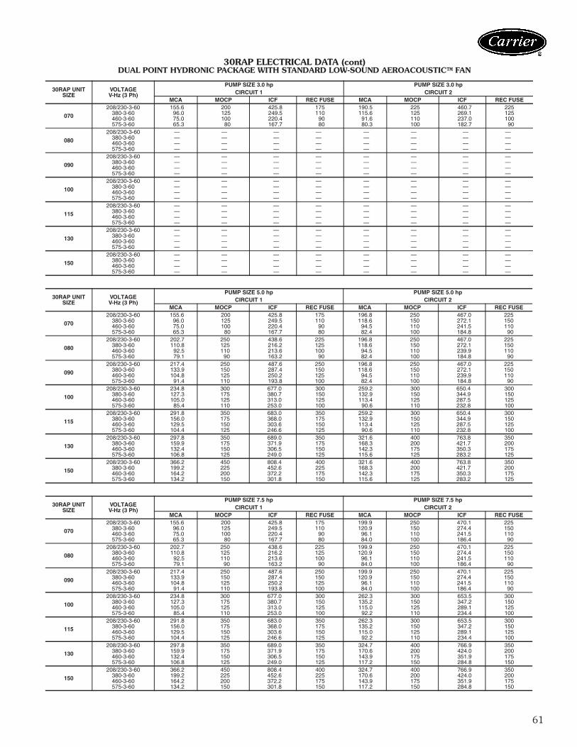
DUAL POINT HYDRONIC PACKAGE WITH STANDARD LOW-SOUND AEROACOUSTIC™ FAN (cont)
LEGEND
NOTES:1. Units are suitable for use on electrical systems where voltage supplied to the unit terminals
is not below or above the listed minimum and maximum limits. Maximum allowable phaseimbalance is: voltage, 2%; amps 10%.
2. All units/modules have dual point primary power connection. (Each unit / module requiresits own power supply.) Main power must be supplied from a field-supplied disconnect.
3. Cooler heater is wired into the control circuit so it is always operable as long as the powersupply disconnect and heater safety device are on.
4. Power draw control circuits include both crankcase heaters (sizes 070-150 only) and coolerheaters (where used). Each compressor on sizes 070-090 has a crankcase heater whichdraws 90 watts of power, while each compressor on sizes 100-150 has a crankcase heaterwhich draws 56 watts of power.
ICF — Instantaneous Current FlowMCA — Minimum Circuit AmpsMOCP — Maximum Overcurrent Protection
Electrical data (cont)
63
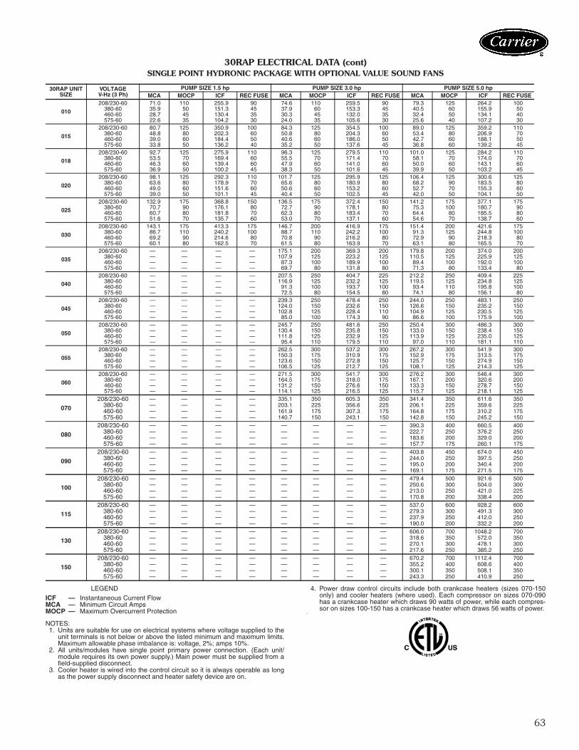
30RAP ELECTRICAL DATA (cont)SINGLE POINT HYDRONIC PACKAGE WITH OPTIONAL VALUE SOUND FANS
LEGEND
NOTES:1. Units are suitable for use on electrical systems where voltage supplied to the
unit terminals is not below or above the listed minimum and maximum limits.Maximum allowable phase imbalance is: voltage, 2%; amps 10%.
2. All units/modules have single point primary power connection. (Each unit/module requires its own power supply.) Main power must be supplied from afield-supplied disconnect.
3. Cooler heater is wired into the control circuit so it is always operable as longas the power supply disconnect and heater safety device are on.
4. Power draw control circuits include both crankcase heaters (sizes 070-150only) and cooler heaters (where used). Each compressor on sizes 070-090has a crankcase heater which draws 90 watts of power, while each compres-sor on sizes 100-150 has a crankcase heater which draws 56 watts of power.
ICF — Instantaneous Current FlowMCA — Minimum Circuit AmpsMOCP — Maximum Overcurrent Protection
64
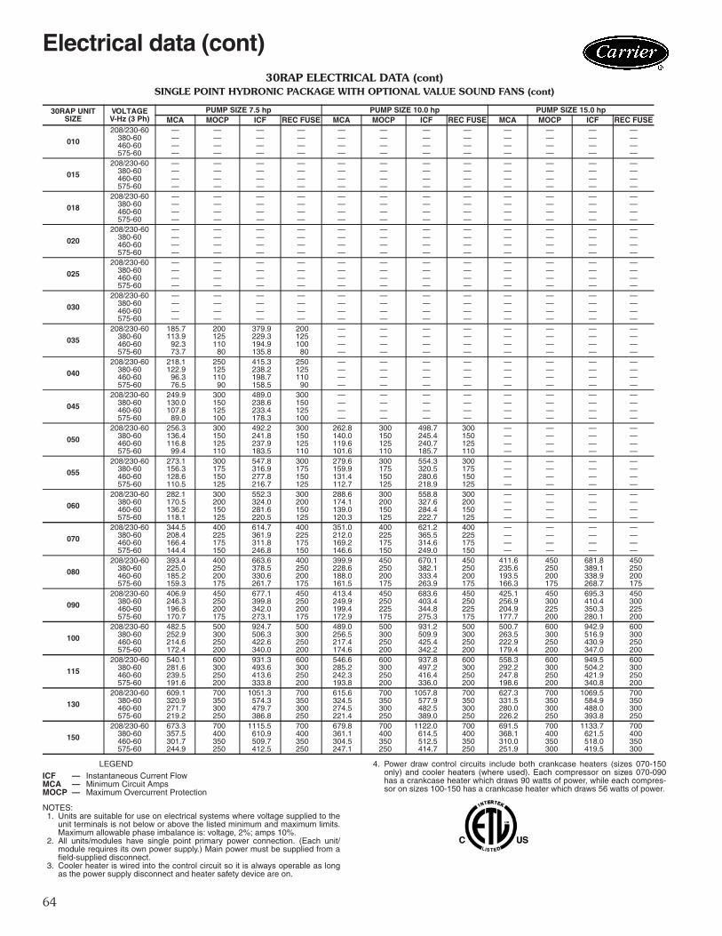
30RAP ELECTRICAL DATA (cont)SINGLE POINT HYDRONIC PACKAGE WITH OPTIONAL VALUE SOUND FANS (cont)
LEGEND
NOTES:1. Units are suitable for use on electrical systems where voltage supplied to the
unit terminals is not below or above the listed minimum and maximum limits.Maximum allowable phase imbalance is: voltage, 2%; amps 10%.
2. All units/modules have single point primary power connection. (Each unit/module requires its own power supply.) Main power must be supplied from afield-supplied disconnect.
3. Cooler heater is wired into the control circuit so it is always operable as longas the power supply disconnect and heater safety device are on.
4. Power draw control circuits include both crankcase heaters (sizes 070-150only) and cooler heaters (where used). Each compressor on sizes 070-090has a crankcase heater which draws 90 watts of power, while each compres-sor on sizes 100-150 has a crankcase heater which draws 56 watts of power.
30RAP ELECTRICAL DATA (cont)DUAL POINT HYDRONIC PACKAGE WITH OPTIONAL VALUE SOUND FANS (cont)
LEGEND
NOTES:1. Units are suitable for use on electrical systems where voltage supplied to the unit terminals
is not below or above the listed minimum and maximum limits. Maximum allowable phaseimbalance is: voltage, 2%; amps 10%.
2. All units/modules have dual point primary power connection. (Each unit/module requires itsown power supply.) Main power must be supplied from a field-supplied disconnect.
3. Cooler heater is wired into the control circuit so it is always operable as long as the powersupply disconnect is on, even if any safety device is open.
4. Power draw control circuits include both crankcase heaters (sizes 070-150 only) and coolerheaters (where used). Each compressor on sizes 070-090 has a crankcase heater whichdraws 90 watts of power, while each compressor on sizes 100-150 has a crankcase heaterwhich draws 56 watts of power.
ICF — Instantaneous Current FlowMCA — Minimum Circuit AmpsMOCP — Maximum Overcurrent Protection
Electrical data (cont)
67
FAN ELECTRICAL DATA(Single Point Standard Low-Sound AeroAcoustic™ Fans)
FAN ELECTRICAL DATA(Single Point Optional Value Sound Fans)
LEGEND
NOTES:1. Units are suitable for use on electrical systems where voltage supplied
to the unit terminals is not below or above the listed minimum and max-imum limits. Maximum allowable phase imbalance is: voltage, 2%;amps 10%.
2. All units/modules have single point primary power connection. (Eachunit/module requires its own power supply.) Main power must be sup-plied from a field-supplied disconnect.
3. The unit control circuit power transformer (24 v, single-phase for allvoltages) is factory supplied.
4. Cooler heater is wired into the control circuit so it is always operable aslong as the power supply disconnect and heater safety device are on.
NOTES:1. Units are suitable for use on electrical systems where voltage supplied to
the unit terminals is not below or above the listed minimum and maximumlimits. Maximum allowable phase imbalance is: voltage, 2%; amps 10%.
2. All units/modules have single point primary power connection. (Each unit/module requires its own power supply.) Main power must be supplied from afield-supplied disconnect.
3. The unit control circuit power transformer (24 v, single-phase for all voltages)is factory supplied.
4. Cooler heater is wired into the control circuit so it is always operable as longas the power supply disconnect and heater safety device are on.
30RAP SIZE PUMP OPTION PUMP SIZE PUMP RPM UNIT VOLTAGE V-Hz (3 Ph) FLA (each)
Microprocessor — The ComfortLink microprocessorcontrols overall unit operation. Its central executive routinecontrols a number of processes simultaneously. Theseinclude internal timers, reading inputs, analog to digitalconversions, fan control, display control, diagnostic con-trol, output relay control, demand limit, capacity control,head pressure control, and temperature reset. Some pro-cesses are updated almost continuously, others every 2 to3 seconds, and some every 30 seconds. The microproces-sor routine is started by switching the Emergency ON-OFFswitch to ON position. Pump control of external pumps(where so configured) or optional internal pump, willenergize the cooler pump to the internal (or CCN) timeschedule (or input occupied signal from external system).
Where dual pumps are utilized, only one pump will beused at a time. The control will start the pump with theleast number of operating hours. When the unit receives acall for cooling (based on a deviation from chilled water setpoint), the unit stages up in capacity to maintain the coolerfluid set point. The first compressor starts 1 to 3 minutesafter the call for cooling. The ComfortLink microproces-sor controls the capacity of the chiller by cycling compres-sors at a rate to satisfy actual dynamic load conditions. Thecontrol maintains leaving-fluid temperature set pointshown on the scrolling marquee display board throughintelligent cycling of compressors. Accuracy depends onloop volume, loop flow rate, load, outdoor-air temperature,number of stages, and particular stage being cycled off. Noadjustment for cooling range or cooler flow rate isrequired, because the control automatically compensatesfor cooling range by measuring both return-fluid tempera-ture and leaving-fluid temperature. This is referred to asleaving-fluid temperature control with return-fluid tempera-ture compensation.
The basic logic for determining when to add or remove astage is a time band integration of deviation from set pointplus rate of change of leaving-fluid temperature. Whenleaving-fluid temperature is close to set point and slowlymoving closer, logic prevents addition of another stage.
If 1° F per minute (0.6° C per minute) pulldown controlhas been selected (adjustable setting), no additional steps ofcapacity are added as long as difference between leaving-fluid temperature and set point is greater than 4° F (2.2° C)and rate of change in leaving-fluid temperature is greaterthan the selected pulldown control rate. If it has been lessthan 90 seconds since the last capacity change, compres-sors will continue to run unless a safety device trips. Thisprevents rapid cycling and also helps return oil during shorton periods.Sensors — Thermistors are used for temperature-sensinginputs to microprocessor. Additional thermistor sensorsmay be used as remote temperature sensors for optionalLCWT (leaving chilled fluid temperature) reset.• Cooler leaving chilled fluid temperature• Cooler entering fluid (return) temperature• Outside-air temperature• Compressor suction temperature
Two refrigerant pressure transducers are used in eachcircuit for sensing suction and discharge pressure. Themicroprocessor uses these inputs to control capacity, theelectronic expansion valve, and fan cycling.
• Saturated condensing temperature• Cooler saturation temperature
Control sequenceOff cycle — If ambient temperature is below 36 F (2 C),cooler heaters (if equipped) are also energized.Start-up — After control circuit switches on, the prestartprocess takes place, then microprocessor checks itself,starts pump (if configured) and waits for temperature tostabilize. The controlled pulldown feature limits compres-sor loading on start-up to reduce demand on start-up andunnecessary compressor usage. The microprocessor limitssupply-fluid temperature decrease (start-up only) to 1° F(0.6° C) per minute.Capacity control — On first call for cooling, micropro-cessor starts initial compressor and fan stage on leadcircuit.
As additional cooling is required, additional compressorsare energized.
Speed at which capacity is added or reduced is con-trolled by temperature deviation from set point and rate oftemperature change of chilled fluid.
The Main Base Board (MBB) responds to temperature ofsupply chilled water to cycle the compressor(s) and to con-trol compressor unloading and loading to match coolingload requirements.
Hot gas bypass valve is energized by the MBB. Valveallows hot gas to pass directly into the cooler circuit on thefinal step of unloading, maintaining constant suction pres-sure and permitting the unit to operate at lower loads withless compressor cycling.
On units equipped with the digital compressor option(available on sizes 010-090), the control will integrate themodulation of the digital compressor into the capacity rou-tine to match cooling load requirements. The digital com-pressor will modulate in 13 steps for sizes 010 and 015,22 steps (11 per compressor) for sizes 020-030, 44 steps(11 per compressor) for sizes 035-060, 55 steps for size070 and 66 steps for sizes 080-090.
The digital scroll option provides better capacity controlby incrementally modulating capacity effectively, increasingthe number of compression stages compared to chillersthat are not equipped with this option. The digital scrollcompressor is not a variable speed device, it modulates thecapacity output by allowing the scroll sets to separate dur-ing operation, alternating between full capacity and zerocapacity. Utilizing a fixed timeframe ratio, the percentageof time that the scroll set is engaged is the percentagecapacity of that compressor.
There are 2 major advantages of this type of capacitycontrol. First, there is closer capacity control operationwith all the available capacity steps compared to the on/offcycling control of conventional scrolls. Second, there ismuch less wear factor on digital scrolls compared to stan-dard scroll compressors because the digital scrolls are notsubject to as many of the shutdown/restart cycles as con-ventional scrolls. Digital scrolls, rather than shutting off,tend to remain on as they vary to deliver the correct capac-ity step.
Controls
72
STANDARD CAPACITY CONTROL STEPS
Additional information — Detailed information on con-trols and operation is available in the Controls, Operation,and Troubleshooting literature included with each unit.Packaged service training programs are also available.Contact your Carrier representative for more information.Dual chiller control — The ComfortLink controllerallows 2 chillers (piped in parallel) to operate as a singlechilled water plant with standard control functions coordi-nated through the master chiller controller. This standardComfortLink feature requires a communication linkbetween the 2 chillers and an additional thermistor andwell in the common supply line.Dynamic ComfortLink controls — Dynamic Com-fortLink�controls keep the chiller on line during periods ofextreme operating conditions. If the entering fluid temper-ature is 85 F (29 C) or higher and the saturated suctiontemperature is 60 F (16 C) or higher the maximum operat-ing pressure (MOP) feature limits the suction to keep thechiller online. The control automatically starts the chiller inthe unloaded state to eliminate the potential of compressoroverload due to high head pressure or low suction pres-sure. The controller will equalize run time on each circuitthrough the lead/lag feature. If a circuit becomes disabled,the control will automatically set the active circuit to lead,keeping the chiller online at a reduced capacity.Standard ComfortLink controls with scrolling mar-quee display module — A four-digit alphanumeric dis-play shows all of the ComfortLink control codes (with 60-character expandable clear language), plus set points, timeof day, temperatures, pressures, and superheat. Additionalinformation can be displayed all at once with the accessoryNavigator™ display.Navigator display module — An optional 4-line,20-character per line display is also available as a field-installed accessory.Low-temperature override — This feature preventsLCWT (leaving chilled fluid temperature) from
overshooting the set point and possibly causing a nuisancetrip-out by the freeze protection.High-temperature override — This feature allowschiller to add capacity quickly during rapid load variations.Abnormal conditions — All control safeties in chilleroperate through compressor sensor board and the micro-processor.
Loss of feedback signal to the MBB will cause the com-pressor(s) to shut down. For other safeties, microprocessormakes appropriate decision to shut down a compressordue to a safety trip or bad sensor reading and displaysappropriate failure code on the display. Chiller holds insafety mode until reset. It then reverts to normal controlwhen unit is reset.Low-pressure safety — Safety cuts out if system pres-sure drops below minimum.High-pressure cutout — Switch shuts down compres-sors if compressor discharge pressure increases to650 psig (4482 kPa).Compressor anti-cycling — This feature limits com-pressor cycling.Loss of flow protection — Proof of flow switches arestandard and installed on all 30RAP chillers.Sensor failures — Failures are detected by themicroprocessor.Temperature reset — The energy management module(EMM) is required for 4 to 20 mA reset of LCWT in con-stant fluid systems. Reset by return fluid, outdoor-air tem-perature, or space temperature does not require thisoption. Reset reduces compressor power usage at partload when design LCWT is not necessary. Humidity con-trol should be considered since higher coil temperaturesresulting from reset will reduce latent heat capacity. Threereset options are offered, based on the following:Return-fluid temperature — Increases LCWT set point asreturn (or entering) fluid temperature decreases (indicatingload decrease). Option may be used in any applicationwhere return fluid provides accurate load indication. Limi-tation of return fluid reset is that LCWT may only be resetto value of design return fluid temperature.Outdoor-air temperature — Increases LCWT as outdoorambient temperature decreases (indicating load decrease).This reset should be applied only where outdoor ambienttemperature is an accurate indication of load.Space temperature — Increases LCWT as space tempera-ture decreases (indicating load decrease). This reset shouldbe applied only where space temperature is an accurateindication of load. An accessory thermistor and the energymanagement module accessory is required.
For details on applying a reset option, refer to unitControls, operation, and Troubleshooting literature.Obtain ordering part numbers for reset option from thePackaged Chiller Builder program or contact your localCarrier representative.Accessory controls — Demand can be limited by con-trolling the chiller capacity through the demand limit con-trol (the energy management module is required for thisfunction). This FIOP (factory-installed option)/accessory
interfaces with microprocessor to control unit so thatchiller’s kW demand does not exceed its setting. It is acti-vated from an external switch or a 4 to 20 mA signal.
The standard ComfortLink controller is programmed toaccept various accessory temperature reset options (basedon outdoor-air temperature [standard], return-fluid temper-ature, or space temperature), that reset the LCWT. Anaccessory thermistor for space temperature reset isrequired. The energy management module (EMM) is onlyrequired for temperature reset that is initiated by a 4 to20 mA signal.Demand limit — If applied, the demand limit functionlimits the total power draw of unit to selected point by con-trolling number of operational compressors during periodsof peak electrical demand.
The energy management module is required for either 2-stage or 4 to 20 mA demand limit.Electronic expansion valve (EXV) — The EXV con-trols refrigerant flow to the cooler for different operatingconditions by moving an orifice to increase or decrease theflow area through the valve based on microprocessorinput. The orifice is positioned by a stepper motor and ismonitored every 3 seconds. The EXV maintains approxi-mately 9° F (5° C) refrigerant superheat entering thecompressor.Diagnostics — The microprocessor may be put througha service test (see Controls, Operation, and Troubleshoot-ing literature). Service test confirms microprocessor isfunctional, informs observer through display the conditionof each sensor and switch in chiller, and allows observer tocheck for proper operation of fans and compressors.
Default settings — To facilitate quick start-ups, 30RAPchillers with ComfortLink controls are pre-configured witha default setting that assumes stand-alone operation sup-plying 44 F (6.7 C) chilled water.
Configuration settings will be based on any optionsor accessories included with the unit at the time ofmanufacturing.
Date and time are set to U.S.A. Eastern Time zone andwill need reconfiguring based on location and local timezone. If operation based on occupancy scheduling isdesired, this will also need to be set during installation.Ice duty — ComfortLink controls have the capability ofreduced leaving fluid temperature operation for thermalstorage, or ice duty. The optional energy managementmodule includes input contacts for the “ice done” signalgenerated by the thermal storage control system. The iceduty feature may be configured to start on an externalinput command or by the ComfortLink standard internalscheduling function. Ice duty may be used in combinationwith any other standard features offered by the energymanagement module and ComfortLink controls.
The production of ice, which is stored for peak coolingdemands, can significantly decrease energy costs. The unitproduces ice (normally at night) by supplying ice storagetanks with low temperature cooling fluid. The chiller takesadvantage of reduced ambient conditions at night for ice-making mode, so the capacity suffers a lower penalty forthe low leaving fluid temperatures.
At peak cooling demands the chiller and the stored icemay share the cooling load to reduce operating costs. Thethermal storage system may potentially reduce the size ofthe chiller plant required to meet demand loads.
74
a30-5514
Typical control wiring schematic
75
Chiller location and clearancesDo not locate near sound sensitive areas without properacoustic consideration. For applications requiring mount-ing a chiller on a building rooftop, consideration should begiven to using rubber-in-shear or spring isolators to mini-mize structure-borne transmission. Unit must be level wheninstalled to ensure proper oil return to the compressors.Clearances must be provided around chillers for airflow,service and local code requirements. See dimensionaldrawings for specific unit clearance requirements. Ensureadequate clearance between adjacent chillers ismaintained. For 30RAP010-060: When parallel chillers are alignedsuch that coils face each other, a minimum of 6 ft(1829 mm) is recommended. When the parallel arrange-ment has only one coil drawing air from the space betweenchillers, a minimum of 3.5 ft (1067 mm) is recommended.When parallel chillers have no coils facing each other (aback-to-back arrangement), be sure to maintain the largerof the recommended service clearances associated witheach chiller (see the certified drawings). Due to NEC(National Electric Code, U.S.A.) regulations, a minimumclearance of 4 ft (1219 mm) must be maintained on theside of the chiller that has an electrical box. Chiller fan dis-charge must be at least as high as adjacent solid walls.Installation in pits is not recommended.
For 30RAP070-150: When chillers are arranged in par-allel, a minimum of 10 ft (3048 mm) between chillers isrecommended. Acceptable clearance on the cooler con-nection side or end opposite the control box of the unitcan be reduced to 3 ft (1 m) without sacrificing perfor-mance as long as the remaining three sides are
unrestricted. Acceptable clearance on the side with a con-trol box can be reduced to 4 ft (1.3 m) due to NEC(National Electric Code, U.S.A.) regulations, without sacri-ficing performance as long as the remaining three sidesare unrestricted. Clearances between chillers in dual chillerapplications may be reduced to 6 ft (1.8 m) without sacri-ficing performance provided the remaining sides are unre-stricted. For acceptable clearance with layout involvingmore than 2 chillers, please contact application engineer-ing.
Oversizing chillersOversizing chillers by more than 15% at design conditionsmust be avoided as the system operating efficiency isadversely affected (resulting in greater or excessive electri-cal demand). When future expansion of equipment isanticipated, install a single chiller to meet present loadrequirements and add a second chiller to meet the addi-tional load demand. It is also recommended that 2 smallerchillers be installed where operation at minimum load iscritical. The operation of a smaller chiller loaded to agreater percentage over minimum is preferred to operatinga single chiller at or near its minimum recommended value.Hot gas bypass should not be used as a means to allowoversizing chillers. Hot gas bypass should be given consid-eration where substantial operating time is anticipatedbelow the minimum unloading step.
Multiple chillersWhere chiller capacities greater than can be supplied by asingle 30RAP chiller are required, or where standby capa-bility is desired, chillers may be installed in parallel. Unitsmay be of the same or different sizes with this piping ar-rangement. However, cooler flow rates must be balancedto ensure proper flow to each chiller. When multiple 30RAP chillers are applied in parallel,and the chillers include the optional hydronic packagewhich contains expansion tanks (sizes 010-060), the indi-vidual chiller expansion tanks must be disconnected and asingle field-supplied expansion tank must be installed in thecommon header. Unit software is capable of controlling two parallel unitsas a single plant by making use of the dual chiller controlfeature. Refer to the Controls, Start-up, Operation, Serviceand Troubleshooting guide for further details. The accesso-ry Chillervisor System Manager can be used to ensureproper staging sequence of up to 8 chillers. Refer to theaccessory Chillervisor System Manager installation instruc-tions for further details. If the dual chiller algorithm is used, and the machines areinstalled in parallel, one chiller must be configured as themaster chiller and the other as the slave. With this configu-ration, an additional leaving fluid temperature thermistormust be installed as shown in the figure on page 76. Parallel chiller control with dedicated pumps is recom-mended. The chiller must start and stop its own waterpump located in its own piping. Check valves are requiredat the discharge of each pump (when the factory hydronicpackage option is chosen, and dual pumps are select-ed, the check valves are automatically supplied). Ifpumps are not dedicated for each chiller, then isolation
6 ft(1.8 m)
MINIMUM*
3.5 ft (1.1 m)MINIMUM†
30RAP010-060 MULTIPLE UNIT SEPARATION
* Minimum for when coils face each other. Less clearance is requiredin other configurations.† Clearance of 3.5 ft is required when a coil faces the wall. Whenthere is no coil facing the wall, see the certified drawing for therequired service clearance.
a30-4873
10 ft(3 m)
MINIMUM
6 ft (1.8 m)MINIMUM
30RAP070-150 MULTIPLE UNIT SEPARATION
a30-4904
Application data
76
valves are required. Each chiller must open and close itsown isolation valve through the unit control (the valve mustbe connected to the pump outputs). If a series application is required, the master/slave con-trol feature cannot be used. Hydronic pump packages maynot be applied in series applications.
Series chillers Where a large temperature drop (greater than 20 F[11.1 C]) is desired or where chiller capacities greater thancan be supplied by a single 30RAP chiller are required orwhere standby capability is required, chillers may beinstalled in series. The leaving fluid temperature sensorsneed not be relocated. However, the cooler minimumentering fluid temperature limitations should be consideredfor the chillers located downstream of other chillers. Whenchillers are operated in a series arrangement, the use of aChillervisor System Manager is recommended.
Cooler water temperature1. Maximum leaving chilled water (fluid) temperature
(LCWT) for the unit is 60 F (15.6 C). Unit can startand pull down with up to 95 F (35 C) entering-fluidtemperature. It is recommended that entering-fluidtemperature not exceed 70 F (21.1 C).
2. Minimum LCWT for fresh water applications is 40 F(4.4 C). For leaving-fluid temperatures between 14and 39.9 F (–10.0 C and 4.4 C) an inhibited anti-freeze solution in the fluid loop is required, but nomodification to the 30RAP chiller (accessory mediumtemperature brine, for example) is required.
NOTE: For leaving-fluid temperatures below 35 F (2 C),neither hot gas bypass nor the digital compressor optionare to be employed.NOTE: Water flowing through cooler should not exceed100 F (38 C).NOTE: The 30RAP010-060 chillers do not require amedium temperature brine modification at any tempera-ture within the chiller application range which is as low as14 F (–10 C) leaving-fluid temperature. For 30RAP070-150, the appropriate field charge adjustment is required.See Controls, Start Up, Operation, Service, and Trouble-shooting Guide for details.
StrainersA 40 mesh strainer is installed in the cooler fluid inlet line,just ahead of the cooler.
Cooler flow/rangeRatings and performance data in this publication are for acooling temperature rise of 10° F (6° C). The 30RAP chill-ers may be operated at a different temperature rise, provid-ing flow limits are not exceeded and corrections to systemguidelines are made. For minimum and maximum coolerflow rates, see the Minimum and Maximum Cooler FlowRates table. A high flow rate is generally limited by themaximum pressure drop that can be tolerated by the unit.The 30RAP chillers are designed for a full load tempera-ture rise of 5° to 20° F (2.8° to 11. 1° C). Use the Pack-aged Chiller Builder Program to obtain the rating if atemperature rise other than 10° F (6° C) is used.Minimum cooler flow (maximum cooler tempera-ture rise) — The minimum cooler flow for standard unitsis shown in Minimum and Maximum Cooler Fluid FlowRates table. When system design conditions require alower flow (or higher rise) than the minimum allowablecooler flow, follow the recommendations below.• Multiple smaller chillers may be applied in series, each
providing a portion of the design temperature rise.• Cooler fluid may be recirculated to raise the flow rate to
the chiller. The mixed temperature entering the coolermust be maintained to a minimum of at least 5° F(2.8° C) above the LCWT and to a maximum of nomore than 20° F (11.1° C) above the LCWT.
NOTE: Recirculation flow is shown below.
Maximum cooler flow — The maximum cooler flow(approximately 5° F [2.8° C] rise) results in a practical max-imum pressure drop through cooler.
Return fluid may bypass the cooler to keep the pressuredrop through the cooler within acceptable limits. This per-mits a higher delta T with lower fluid flow through coolerand mixing after the cooler. The mixed temperatureentering the cooler must be maintained to a minimum of atleast 5° F (2.8° C) above the LCWT and to a maximum ofno more than 20° F (11.1° C) above the LCWT.NOTE: Bypass flow is shown on the following page.
MASTERCHILLER
SLAVECHILLER
LEAVINGFLUID
RETURNFLUID
THERMISTORWIRING*
INSTALL DUAL CHILLER LWTLEAVING FLUID TEMPERATURETHERMISTOR (T10) HERE
*Depending on piping sizes, use either:• HH79NZ014 sensor/10HB50106801 well (3-in. sensor/well)• HH79NZ029 sensor/10HB50106802 well (4-in. sensor/well)
PARALLEL CHILLER INSTALLATION
RECIRCULATION FLOW
a30-4042
Application data (cont)
77
Variable cooler flow ratesVariable flow rates may be applied to a standard chiller.The unit will, however, attempt to maintain a constantleaving chilled water temperature. In such cases, minimumflow must be in excess of minimum flow given in the Mini-mum and Maximum Cooler Fluid Flow Rates table onpage 79, and minimum fluid volume in circulation must bein excess of those values shown for normal air-conditioningapplications in the Minimum Fluid Volume in Circulationtable. Flow rate must change in steps of less than 10% perminute. Apply 6 gal. or more per ton (6.5 L per kW) waterloop volume minimum if flow rate changes more rapidly.
The 30RAP chiller is available without a hydronic pump-ing package, a constant-speed pumping package, or with avariable-speed drive pumping package on sizes 070-150.Traditional pumping systems incorporate constant-speeddrives and waste energy by relying upon throttling valves asthe only means to control flow. A more energy-efficientapproach to this issue is use a variable-speed drive. The30RAP070-150 units are now available with an optionalvariable-speed hydronic package with sensorless technol-ogy to meet this market requirement.
The major cost of a pump over its lifetime will be energyconsumption and maintenance, and both of these factorswill be reduced using variable-speed pumping. Energy issaved by the combination of lowering the pump speed inconjunction with the resulting lowering of pumping systemresistance when conditions permit. Maintenance benefitsfrom the sensorless pumping system include the lack of theneed to maintain remote sensors as well as the beneficialeffects of lower speed/pressure on the pump and pumpbearings.
Another advantage associated with variable-speedpumping is reduced system noise in part load operationwhen the pump is running at lower speeds. The variable-speed pump package offered on the 30RAP is offeredboth in single and dual-pump designs. In the dual pumpcase, in which one pump is the back-up of the other, eachpump connection is fitted with an isolation valve whichallows one pump to be isolated for service with the otherpump still operating.
As already mentioned, the 30RAP variable-speedhydronic package employs sensorless technology. Theterm "sensorless" means that no remote sensors arerequired for pump operation. The sensorless pumpcontrol monitors system requirements for pump speed andpower. The hydronic unit is provided with a pre-definedcontrol curve to automatically adjust speed at all operating
conditions. Pump performance and characteristic curvesfor multiple speeds are programmed into the speed-con-troller memory. The pre-programmed information includespower, pressure and flow throughout the entire range ofthe pump. During chiller operation, the power and speedof the pump are monitored. This enables the controller toestablish the hydraulic performance, and to position thepump's head-flow characteristic. Although this curve is pre-defined, it is also fully field adjustable. The pump has agraphical user interface, and the graphic keypad can alsobe used to allow manual pump speed control.
This variable-speed pumping system easily connects toBMS (Building Management System) systems (BACnet isstandard, and LON can be obtained via special order). Thepumps may be controlled directly by the BMS system. Thesensorless feature can also be switched off to allow the useof either a 0 to 10 VDC signal or a 0 to 20 mA signal.
For multiple chiller applications employing the variable-speed pumping package, such as chillers operated in a par-allel arrangement, the drives must be connected by controlwiring and set up to run the same speed. This is to preventsurging or hunting of the speed set point. One drive willact as the master while the other slave drive will run at thesame speed. The master drive may be controlled by a 0 to10 VDC signal, a 0 to 20 mA signal, or a BMS. The drivemust be configured to not use the sensorless function inthis arrangement.
A typical example of a chiller operating with a variable-speed pumping system would be the case when the userrequires the chiller to operate with a constant fluid temper-ature difference as the load is reduced. This can be accom-plished with the 30RAP variable-speed pumping packagewith the understanding that the minimum allowable flowfor the chiller must be respected. Once that limit isreached, the flow cannot be further reduced. To accom-plish this purpose, the minimum speed of the drive is pre-set based upon the chiller size that is being employed.
As a specific example, let us say the schedule calls for a90-ton, fresh-water chiller, and it is desired to have a con-stant 10-degree temperature difference in part load opera-tion (say 54 to 44 F). The schedule calls for 216 gpm atfull load based upon the desired capacity and the fluid tem-perature difference. A constant temperature difference inpart load operation is essentially the same as providingflow in direct proportion to chiller load. In the presentexample, this means that 100% load will run at the sched-uled 216 gpm, 90% load will be 194 gpm, etc. down tothe minimum allowable flow for this unit size, which, in thecase of a 30RAP090 unit, is 107 gpm. The chiller in thisexample will therefore be able to run down to just under50% load while approximately maintaining a constant 10degree fluid temperature difference, and then the flow willbe held constant for all lower loads. Throughout the rangein which flow is reduced (down to minimum allowableflow), the pump speed is proportionally reduced, resultingin pump energy savings.
Fluid loop volumeThe minimum volume of fluid required to be in circulationis a function of the number of compressors in the chiller,the type of application, and whether or not a device
BYPASS FLOW
a30-533
78
providing additional unloading steps is employed. The min-imum fluid in circulation must equal or exceed the values inthe following table. Note that in process cooling applica-tions, or for operation at ambient temperatures below32 F (0° C) with low loading conditions, there should bemore volume than is required for normal air-conditioningapplications.
MINIMUM FLUID VOLUME IN CIRCULATION
LEGEND
To achieve this fluid volume, it is often necessary to installa tank in the loop. The tank should be baffled to ensurethere is no stratification and that water (or brine) enteringthe tank is adequately mixed with liquid in the tank. A fluidstorage tank is available as an accessory. The piping between the chiller and the accessory tank canbe done to allow the tank to be on the return side of thechiller (tank piped to chiller inlet) or the supply side of thechiller (tank piped to the chiller outlet). However, it is rec-ommended that the tank be piped to the return side of thechiller to buffer any changes in load to allow more stablechiller operation.
Tank volume and weightA properly baffled storage tank is available as an accessoryon 30RAP010-060. These tanks are designed tophysically fit beneath the corresponding 30RAP unit, tak-ing up the same footprint. Available volume is as follows:30RAP010,015 83 gallons (314 liters)30RAP018-030 119 gallons (450 liters)30RAP035-060 241 gallons (912 liters)
Storage tank weight (water weight included) is as follows:30RAP010,015 1673 lb (759 kg)30RAP018-030 2193 lb (995 kg)30RAP035-060 4361 lb (1978 kg)NOTE: This tank will obtain power from the main unit. Noseparate power source is required.NOTE: Units with storage tanks weigh considerably morethan units without tanks.
Cooler fouling factorThe fouling factor used to calculate tabulated ratings is0.00010 ft2 � hr � °F/Btu (0.000018 m2 � °C/W). As foul-ing factor is increased, unit capacity decreases and com-pressor power increases. Use the NACO (North AmericanCommercial Operation) Packaged Chiller Builder for cor-rections to published ratings.
Cooler and hydronic system freeze protectionFreeze protection for down to –20 F (–28.9 C) for thecooler and hydronic package is available as a factory-installed option. Since power is sometimes lost for extend-ed periods during winter storms, freeze protection provid-ed by heater tapes will be effective only if a back-up powersupply can be assured for the unit’s control circuit, heaterand cooler pump. If not protected with an antifreeze solu-tion, draining the cooler and outdoor piping is recom-mended if the system will not be used during freezingweather conditions.
Two conditions that must be considered when determin-ing antifreeze concentration are leaving water set pointand ambient freeze conditions. Both of these parameterscan help determine the recommended concentration level.Higher concentration must be used to adequately protectthe machine.NOTE: Use only antifreeze solutions approved for heat ex-changer duty.
For applications in which the leaving water temperatureset point is less than 40 F (4.4 C), a suitable inhibited anti-freeze solution must be used. The solution concentrationmust be sufficient to protect the chilled water loop to afreeze protection (first crystals) concentration of at least15° F (8.3º C) below the leaving water temperature setpoint.
If the chiller refrigerant or fluid lines are in an area whereambient conditions fall below 34 F (1º C), it is required thatan antifreeze solution be added to protect the unit and fluidpiping to a temperature of 15º F (8.3º C) below the lowestanticipated ambient temperature.
Select concentration based on either burst or freeze pro-tection as dictated by the application. If the chiller does notoperate during the winter, nor is a start-up expected, aburst protection concentration is recommended. Thisconcentration may not be high enough to pump the fluidthrough the unit. Burst protection is typically a lower con-centration that will provide better performance from themachine. If the chiller does operate during winter, a freezeprotection concentration is recommended. This concentra-tion will be high enough to keep the fluid in a conditionthat it can be pumped at low ambient conditions.
* For minimum cooler flow rate with brine applications, refer to E-CATsoftware performance.
Consult glycol fluid manufacturers for burst protectionrecommendations and fluid specifications.
High ambient temperature operationHigh outdoor ambient chiller start-up and operation is pos-sible for standard 30RAP chillers at ambient temperaturesup to 120 F (50 C) at nominal voltage. The unit will addi-tionally be able to stay running at reduced capacity up to125 F (52 C).
Low ambient temperature operationUnits will operate down to –20 F (–29 C) on size 010 and015 units, 45 F (7 C) on size 018-030 units, and 32 F(0° C) on size 035-150 units as standard.
Operation to –20 F (–29 C) for size 018-150 unitsrequires optional Motormaster® V condenser head pres-sure control (included as standard on size 010 and 015units) as well as wind baffles. Inhibited propylene glycol orother suitable corrosion-resistant anti-freeze solution mustbe field supplied and installed in all units for unit operationbelow 32 F (0° C). Solution must be added to fluid loop toprotect loop down to 15° F (8° C) below minimum operat-ing ambient temperature. Concentration should be basedon expected minimum temperature and either “Burst” or“Freeze” protection levels. At least 6 gal. per ton (6.5 Lper kW) of fluid volume is the recommended minimum fora moderate system load.NOTE: In order for a chiller to operate at –20 F (–29 C)ambient temperature, the minimum load on the chillermust be above the minimum step of unloading.NOTE: As an alternative to requiring a glycol solution, thecooler may be remotely located. Burying refrigerant lines isnever permitted.
Altitude correction factorsCorrection factors must be applied to standard ratingsat altitudes above 2000 ft (610 m). Use the NACO Pack-aged Chiller Builder to determine the altitude effect onpeformance.
Water system overview (closed loop systems only)The 30RAP chillers are designed for use with closed sys-tems, meaning that there is no more than one water-airinterface in the water loop. Cooling tower loops, forexample, have two water-air interfaces (sump and nozzles)and would thus be classified as open, whereas a correctlydesigned chilled water loop with the only water-air inter-face being in the expansion tank is closed. Since closedand open water systems behave very differently, the follow-ing assumes that the chilled water loop is closed. A systeminstalled incorrectly such that air is not handled properly —pipe leaks, vent leaks, air in pipes, etc. — may behave asan open system and thus have unsatisfactory operation.Pump seal wear can also cause leaks that cause poor sys-tem operation. Proper closed system design and installation proceduresshould be followed closely. The system must be con-structed with pressure tight components and thoroughlytested for installation leaks. Factory-supplied hydronic sys-tems are available with single or dual (for back-up) pumps.The factory-installed system includes all of the componentswithin the dashed lines shown in the figure on page 56. Installation of water systems should follow sound engi-neering practice as well as applicable local and industrystandards. Improperly designed or installed systems maycause unsatisfactory operation and/or system failure. Con-sult a water treatment specialist or appropriate literaturefor information regarding filtration, water treatment, andcontrol devices. A typical installation with components thatmight be installed with the hydronic package of the 30RAPunit is shown on pages 53-55.
IMPORTANT: Glycol anti-freeze solutions are highlyrecommended since heater tapes provide no protec-tion in the event of a power failure.
80
It is recommended that isolation (shutoff) valves be placedexterior to the unit to allow removal and service of theentire pump assembly, if necessary. Also, if the unit is iso-lated with valves, a properly sized pressure relief valveshould be installed in the piping between the unit and thevalves, following all applicable state and local codes.
Water system cleaningProper water system cleaning is of vital importance. Exces-sive particulates in the water system can cause excessivepump seal wear, reduce or stop flow, and cause damage ofother components. Water quality should be maintainedwithin the limits indicated in the Water Quality Characteris-tics and Limitations table.
1. Install a temporary bypass around the chiller to avoidcirculating dirty water and particulates into the pumppackage and chiller during the flush. Use a temporarycirculating pump during the cleaning process. Also,be sure that there is capability to fully drain the sys-tem after cleaning.
2. Be sure to use a cleaning agent that is compatiblewith all system materials. Be especially careful if thesystem contains any galvanized or aluminum compo-nents. Both detergent-dispersant and alkaline-disper-sant cleaning agents are available.
3. It is a good idea to fill the system through a watermeter. This provides a reference point for the futurefor loop volume readings, but it also establishes thecorrect quantity of cleaner needed in order to get therequired concentration.
4. Use a feeder/transfer pump to mix the solution andfill the system. Circulate the cleaning system for thelength of time recommended by the cleaning agentmanufacturer.a. After cleaning, drain the cleaning fluid and flush
the system with fresh water.b. A slight amount of cleaning residue in the system
can help keep the desired, slightly alkaline, waterpH of 8 to 9. Avoid a pH greater than 10, sincethis will adversely affect pump seal components.
c. A side stream filter is recommended during thecleaning process. Filter side flow rate should beenough to filter the entire water volume every 3 to4 hours. Change filters as often as necessary dur-ing the cleaning process.
d. Remove temporary bypass when cleaning iscomplete.
A strainer with a blow-down valve is standard on all30RAP units, both with and without hydronic packages.The blow-down valve allows removal of particulates caughtin the strainer without complete removal of the screen. Afemale NPT connection is provided on the valve, allowinghose connection for drainage outside the unit. The ComfortLink controls provided have a built-in fea-ture to remind building owners or operators to clean thestrainer by discharging the blow-down valve at a pre-settime interval. Properly installed and cleaned systems willrarely need the strainer cleaned after the initial fill. Thistime interval is user-configurable.
WATER QUALITY CHARACTERISTICSAND LIMITATIONS
*Sulfides in the water quickly oxidize when exposed to air, requiring that noagitation occur as the sample is taken. Unless tested immediately at thesite, the sample will require stabilization with a few drops of one Molarzinc acetate solution, allowing accurate sulfide determination up to 24hours after sampling. A low pH and high alkalinity cause system prob-lems, even when both values are within the ranges shown. The term pHrefers to the acidity, basicity, or neutrality of the water supply. Below 7.0,the water is considered to be acidic. Above 7.0, water is considered to bebasic. Neutral water contains a pH of 7.0.
†Dissolved carbon dioxide can either be calculated from the pH and totalalkalinity values, shown below, or measured on the site using a test kit.Dissolved Carbon Dioxide, PPM = TA x 2[(6.3-pH)/0.3] where TA = Total Alka-linity, PPM as CaCO3.
Condenser coil protection (Enviro-Shield™)Refer to the environmental selection guides for more infor-mation. If the standard Novation® (microchannel) coil doesnot meet the corrosion requirements for a given applica-tion, an e-coated Novation coil option is available. For spe-cific geographical recommendations, please refer to theNACO Packaged Chiller Builder program.E-coated Novation® coils have an extremely flexibleand durable epoxy coating uniformly applied to all coil sur-faces. Unlike brittle phenolic dip and bake coatings, e-coatprovides superior protection with unmatched flexibility,edge coverage, metal adhesion, thermal performance andmost importantly, corrosion resistance. E-coated coilsprovide this protection since all coil surfaces are complete-ly encapsulated from environmental contamination.
Electrical/utility interestsEnergy management — Use of energy managementpractices can significantly reduce operating costs, espe-cially during off-peak modes of operation. Demand limitingand temperature reset are 2 techniques for accomplishingefficient energy management. See Demand Limiting (alsocalled load shedding) section on this page for furtherdetails.Demand limiting (load shedding) — When a utility’sdemand for electricity exceeds a certain level, loads areshed to keep electricity demand below a prescribed maxi-mum level. Typically, this happens on hot days when airconditioning is most needed. The energy managementmodule (EMM) can be added to accomplish this reduction.Demand may be limited on unit by resetting the fluidtemperature, or by unloading the chiller to a given prede-termined percentage of the load. Demand limit may alsobe driven by an external 4 to 20 mA signal. These features
WATER CHARACTERISTIC QUALITY LIMITATIONAlkalinity (HCO3-) 70 – 300 ppm
Sulfate (SO42-) Less than 70 ppm
HCO3-/SO42- Greater than 1.0Electrical Conductivity 10 – 500��S/cmpH 7.5 – 9.0Ammonium (NH3) Less than 2 ppmChorides (Cl-) Less than 300 ppmFree chlorine (Cl2) Less than 1 ppm
Hydrogen Sulfide (H2S)* Less than 0.05 ppm
Free (aggressive) CarbonDioxide (CO2)†
Less than 5 ppm
Total Hardness (dH) 4.0 – 8.5Nitrate (NO3) Less than 100 ppm
Iron (Fe) Less than 0.2 ppmAluminum (Al) Less than 0.2 ppmManganese (Mn) Less than 0.1 ppm
Application data (cont)
81
require a signal from an intelligent central control. Do notcycle demand limiter for less than 10 minutes on and5 minutes off. Duty cycling cycles electrical loads at regularintervals regardless of need. This reduces the electricaloperating costs of building by “fooling” demand indicatingdevices. Duty cycling of compressors or fans is not recom-mended since motor winding and bearing life will sufferfrom constant cycling.Remote on-off controlRemote on-off control may be applied by hard-wired con-nection (see Controls and Troubleshooting literature) or byconnection to a Carrier Comfort Network® (CCN) system.Optional hydronic system selectionSelect pump gpm from resulting chiller selection and totalpressure loss in the system plus the chiller internal pressureloss.NOTE: Maximum gpm (L/s), pressure and pump hp mustnot exceed maximum on pump curve.NOTE: Optional hydronic system is available in constant-speed configuration on all models. It is also available inVFD configuration on sizes 070-150, as described in Vari-able Cooler Flow Rates section.
Pump flow can be reduced by using the factory-suppliedtriple-duty valve up to 10%. Beyond that, impellertrimming is recommended to reduce energy consumption.Follow local codes or ASHRAE 90.1 recommendations.Contact your Carrier representative for specific amount oftrim required.
Expansion tank supplied (sizes 010-060 only) will allowloop expansion due to ambient fluctuations for loop vol-umes of up to the values in the table below. If loop volumeexceeds the maximum loop volume, a larger expansiontank must be field supplied.
The supplied expansion tanks have the followingspecifications: 30RAP010-030 — 4.4 total gal. (17.0 L)and 3.2 gal. (12.4 L) acceptance volume, 30RAP035-060— 10.3 total gal. (39.0 L) and 10.3 gal. (39.0 L) accep-tance volume.
MAXIMUM LOOP VOLUME
LEGEND
Maximum loop volume is based on typical system pres-sure of 12 psig (83 kPa) and 30 psig (207 kPa) of mini-mum and maximum pressures, and 100 F (37.8 C) meantemperature.
Parallel chillers with hydronic packages require thatpump inlets be equalized to prevent pump cavitation.
Pump expansion tanks must be removed and locatedtogether in the common pump suction header. All materi-als needed for expansion tank relocation are field supplied.Appropriate measures must be taken for freeze protection.Air separationFor proper system operation, it is essential that waterloops be installed with proper means to manage air in thesystem. This is typically done by the installing contractor.Free air in the system can cause noise, reduce terminal out-put, stop flow, or even cause pump failure due to pumpcavitation. For closed systems, equipment should be pro-vided to eliminate all air from the system. The amount of air that water can hold in solution dependson the pressure and temperature of the water/air mixture.Air is less soluble at higher temperatures and at lower pres-sures. Therefore, separation can best be done at the pointof highest water temperature and lowest pressure. Typical-ly, this point would be on the suction side of the pump asthe water is returning from the system or terminals. Gener-ally speaking, this is the best place to install an air separa-tor, if possible.
1. Install automatic air vents at all high points in the sys-tem. (If the 30RAP unit is located at the high point ofthe system, a vent can be installed on the pipingentering the heat exchanger on the ¼-in. NPT femaleport.)
2. Install an air separator in the water loop, at the placewhere the water is at higher temperatures and lowerpressures — usually in the chilled water return piping.On a primary-secondary system, the highest tempera-ture water is normally in the secondary loop, close tothe decoupler. Preference should be given to thatpoint on the system. In-line or centrifugal air separa-tors are readily available in the field.
It may not be possible to install air separators at the placeof lowest pressure and highest temperature. In such cases,preference should be given to the points of highesttemperature. It is important that pipe be sized correctly sothat free air can be moved to the point of separation. Gen-erally, a water velocity of at least 2 ft per second (0.6 mper second) will keep free air entrained and prevent it fromforming air pockets. Automatic vents should be installed at all physically elevat-ed points in the system so that air can be eliminated duringsystem operation. Provision should also be made for man-ual venting during the water loop fill. It is important thatthe automatic vents be located in accessible locations formaintenance purposes, and that they be located wherethey can be prevented from freezing.Minimum time to power chiller before start-upIn order to ensure that the crankcase heaters are providedsufficient time to raise the crankcase temperature to the re-quired operating point, power must be applied to the chill-er and the compressor circuit breakers must be on a mini-mum of 24 hours before chiller start-up. This requirementapplies to sizes 070-150. It is also applicable to all remotecooler applications (all sizes).
(35 to 528 Nominal kW)Carrier Model Number: 30RAPPart 1 — General1.01 SYSTEM DESCRIPTION
Microprocessor controlled, air-cooled liquid chillerutilizing scroll compressors, low sound fans, elec-tronic expansion valve, optional hydronic pump sys-tem, and fluid storage tank (storage tank on models010-060 only).
1.02 QUALITY ASSURANCEA. Unit shall be rated in accordance with AHRI Stan-
dard 550/590, latest edition (U.S.A.) and all unitsshall be ASHRAE 90.1 compliant.
B. Unit construction shall comply with ASHRAE 15Safety Code, UL latest edition, and ASME applica-ble codes (U.S.A. codes).
C. Unit shall be manufactured in a facility registered toISO 9001 Manufacturing Quality Standard.
D. Unit shall be full load run tested at the factory.1.03 DELIVERY, STORAGE AND HANDLING
A. Unit controls shall be capable of withstanding150 F (66 C) storage temperatures in the controlcompartment.
B. Unit shall be stored and handled per unit manufac-turer's recommendations.
Part 2 — Products2.01 EQUIPMENT
A. General:Factory assembled, single-piece chassis, air-cooledliquid chiller. Contained within the unit cabinet shallbe all factory wiring, piping, controls, refrigerantcharge (R-410A), and special features required priorto field start-up.
B. Unit Cabinet:1. Frame shall be of heavy-gage, galvanized steel.2. Exterior panels shall be galvanized steel with a
baked enamel powder or pre-painted finish.3. Cabinet shall be capable of withstanding
500-hour salt spray test in accordance with theASTM (U.S.A.) B-117 standard.
C. Fans:1. Standard condenser fans shall be direct-driven,
9-blade airfoil cross-section, reinforced polymerconstruction, shrouded-axial type, and shall bestatically and dynamically balanced with inher-ent corrosion resistance.
2. Fan operation shall allow reduced sound levelsduring scheduled unoccupied operating periods.Manufacturers without unoccupied reducedsound capability shall submit 1/3 octave banddata and sound power data as measured
according to AHRI 370 as confirmation of unitsound characteristics.
3. Air shall be discharged vertically upward.4. Fans shall be protected by coated steel wire
2. Compressor motors shall be cooled by refriger-ant gas passing through motor windings andshall have either internal line break thermal andcurrent overload protection or external currentoverload modules with compressor temperaturesensors.
3. Compressors shall be mounted on rubber inshear vibration isolators.
4. Staging of compressors shall provide unloadingcapability. Digital compressor unloading controlshall be available as an option (sizes 010-090only).
5. Each compressor (sizes 070-150 only) shall beequipped with crankcase heaters to minimize oildilution. Crankcase heaters are not required onsizes 010-060 due to very low refrigerantcharge.
E. Cooler:1. Cooler shall be rated for a refrigerant working-
side pressure of 505 psig (3482 kPa) on sizes010-025, 565 psig (3896 kPa) on sizes 030-060, and 450 psig (3103 kPa) on sizes 070-150 and shall be tested for a maximum water-side pressure of 300 psig (2068 kPa) or150 psig (1034 kPa) when optional hydronicpackage is installed.
2. Shall be single-pass, ANSI type 316 stainlesssteel, brazed plate construction.
3. Shell shall be insulated with 3/4-in. (19 mm)closed-cell, polyvinyl-chloride foam with a maxi-mum K factor of 0.28.
4. Shall incorporate 2 independent refrigerant cir-cuits on sizes 035 to 150; sizes 010 to 030shall have one independent refrigerant circuit.
5. Cooler shall have optional factory-installedheater, to protect cooler from ambient tempera-ture freeze down to –20 F (–29 C).
6. Unit shall be provided with a factory-installedflow switch.
7. All connections shall use standard Victaulic-typefittings.
8. Cooler fluid inlet line shall have a 40 meshstrainer just ahead of the cooler.
F. Condenser:1. Coil shall be air-cooled Novation® heat
exchanger technology with microchannel(MCHX) coils and shall have a series of flattubes containing a series of multiple, parallel
Guide specifications
84
flow microchannels layered between therefrigerant manifolds.
2. Coils shall consist of a two-pass arrangement.Coil construction shall consist of aluminumalloys for fins, tubes, and manifolds in combina-tion with a corrosion-resistant coating.
3. Tubes shall be cleaned, dehydrated, and sealed.4. Assembled condenser coils shall be leak tested
and pressure tested at 656 psig (4522 kPa).G. Refrigeration Components:
Refrigerant circuit components shall include filterdrier, moisture indicating sight glass, electronicexpansion device, discharge and liquid service valves(sizes 070-150 only) and complete operating chargeof sides both refrigerant R-410A and compressoroil.
H. Controls, Safeties, and Diagnostics:1. Unit controls shall include the following mini-
mum components:a. Microprocessor with non-volatile memory.
Battery backup system shall not be accepted.b. Separate terminal block for power and
controls.c. Control transformer to serve all controllers,
relays, and control components.d. ON/OFF control switch.e. Replaceable solid-state controllers.f. Pressure sensors shall be installed to mea-
sure suction and discharge pressure for eachcircuit. Thermistors shall be installed to mea-sure cooler entering and leaving fluid tem-peratures, outdoor ambient temperature,and suction temperature. Provision for fieldinstallation of accessory sensor to measurecompressor return gas temperature.
2. Unit controls shall include the followingfunctions:a. Automatic circuit lead/lag for dual circuit
chillers.b. Hermetic scroll compressors are mainte-
nance free and protected by an auto-adaptivecontrol that minimizes compressor wear.
c. Capacity control based on leaving chilledfluid temperature and compensated by rateof change of return-fluid temperature withtemperature set point accuracy to 0.1° F(0.06° C).
d. Limiting the chilled fluid temperature pull-down rate at start-up to an adjustable rangeof 0.2° F to 2° F (0.11° C to 1.1° C) perminute to prevent excessive demand spikesat start-up.
e. Seven-day time schedule.f. Leaving chilled fluid temperature reset from
return fluid and outside air temperature.
g. Chilled water pump start/stop control andprimary/standby sequencing to ensure equalpump run time.
h. Dual chiller control for parallel chiller appli-cations without addition of hardwaremodules and control panels (additionalthermistors and wells are required).
i. Timed maintenance scheduling to signalmaintenance activities for pumps, condensercoil cleanings, strainer maintenance anduser-defined maintenance activities.
j. Boiler enable signal to initiate system heat-ing mode.
k. Low ambient protection to energize coolerand hydronic system heaters.
l. Periodic pump start to ensure pump sealsare properly maintained during off-seasonperiods.
m. Single step demand limit control activated byremote contact closure.
n. Nighttime sound mode to reduce the soundof the machine by a user-defined schedule.
3. Diagnostics:a. The control panel shall include, as standard,
a scrolling marquee display capable of indi-cating the safety lockout condition bydisplaying a code for which an explanationmay be scrolled at the display.
b. Information included for display shall be:1) Compressor lockout.2) Loss of charge.3) Low fluid flow.4) Cooler freeze protection.5) Cooler set point.6) Chilled water reset parameters.7) Thermistor and transducer malfunction.8) Entering and leaving-fluid temperature.9) Compressor suction temperature.
10) Evaporator and condenser pressure.11) System refrigerant temperatures.12) Chiller run hours.13) Compressor run hours.14) Compressor number of starts.15) Low superheat.16) Time of day:
a) Display module, in conjunction withthe microprocessor, must also becapable of displaying the output(results) of a service test. Service testshall verify operation of everyswitch, thermistor, fan, and com-pressor before chiller is started.
b) Diagnostics shall include the abilityto review a list of the 20 most recentalarms with clear language descrip-tions of the alarm event. Display ofalarm codes without the ability forclear language descriptions shall beprohibited.
Guide specifications (cont)
85
c) An alarm history buffer shall allowthe user to store no less than 20alarm events with clear languagedescriptions, time and date stampevent entry.
d) The chiller controller shall includemultiple connection ports for com-municating with the local equipmentnetwork, the Carrier ComfortNetwork® (CCN) system and accessto chiller control functions from anypoint on the chiller.
e) The control system shall allow soft-ware upgrade without the need fornew hardware modules.
4. Safeties:a. Unit shall be equipped with thermistors and
all necessary components in conjunctionwith the control system to provide the unitwith the following protections:1) Loss of refrigerant charge.2) Reverse rotation.3) Low chilled fluid temperature.4) Thermal overload.5) High pressure.6) Electrical overload.
b. Factory pump motors shall have externalovercurrent protection.
I. Operating Characteristics:1. Unit shall be capable of operating down to
–20 F (–29 C) on size 010 and 015 units, 45 F(7 C) on size 018-030 units, and 32 F (0° C) onsize 035-150 units as standard.
2. Unit shall be capable of starting and running atoutdoor ambient temperatures up to 120 F(50 C) for all sizes. Unit shall additionally beable to stay online when running with a 125 F(52 C) ambient temperature.
3. Unit shall be capable of starting up with 95 F(35 C) entering fluid temperature to the cooler.
J. Fan Motors:1. Condenser fans shall be direct-drive Aero-
Acoustic™ type, discharging air verticallyupward.
2. All condenser fan motors shall be totallyenclosed 3-phase type with permanently lubri-cated ball bearings, class F insulation and inter-nal, automatic reset thermal overloadprotection or manual reset calibrated circuitbreakers.
3. Shafts shall have inherent corrosion resistance.4. Fan blades shall be statically and dynamically
balanced.5. Condenser fan openings shall be equipped with
PVC coated steel wire safety guards.
K. Electrical Requirements:1. Unit/module primary electrical power supply
shall enter the unit at a single electrical box(includes option for dual point connection onsizes 070-150).
2. Unit shall operate on 3-phase power at the volt-age shown in the equipment schedule.
3. Control points shall be accessed through termi-nal block.
4. Unit shall be shipped with factory control andpower wiring installed.
L. Chilled Water Circuit:1. Chilled water circuit shall be rated for 300 psig
(2068 kPa). Units with optional pump packageare rated for 150 psig (1034 kPa) workingpressure.
2. Solid-state flow monitor with integral relay shallbe factory installed and wired.
3. Brass body strainer with 40 mesh screen andball type blow down.
4. Optional hydronic package (applies to all unitsizes except as noted, with or without the use ofa VFD [variable frequency drive]):a. Field pipe connections shall be copper Vic-
taulic type.b. Optional single or primary/stand-by opera-
tion pump systems. Dual pump systems shallhave a pump discharge check valve.
c. Pumps shall be single stage design, capableof being serviced without disturbing pipingconnections.1) Pump casing shall be of class 30 cast
iron.2) The impeller shall be of cast bronze,
closed type, dynamically balanced,keyed to the shaft and secured by lock-ing cap screw.
3) The hydronic kit will be provided witha flush line connection to ensure lubrica-tion at the seal face and allow forpositive venting of the seal chamber.
4) Pump shall be rated for 150 psig(1034 kPa) working pressure.
5) The pump case shall have gage tappingsat the suction and discharge nozzles andinclude drain ports.
7) Each pump shall be factory tested perHydraulic Institute Standards.
8) Pump motors shall be VFD compatible.d. Fluid expansion tank (sizes 010-060) shall be
factory installed within the chiller cabinetinsulates, pre-charged and rated for a maxi-mum working pressure of 150 psig(1034 kPa).
86
e. Water pressure taps (2) shall be factoryinstalled across the cooler and rated for150 psig (1034 kPa).
f. Balancing valve shall be factory installed toset flow gage ports shall be factory-installedand rated for 300 psig (2068 kPa).
g. Hydronic assembly shall have factory-supplied electric freeze protection to –20 F(–29 C) when optional heaters are used.
h. Piping shall be type-L seamless coppertubing.
5. With VFD (these comments are applicable inaddition to the comments in section L.4 whenthe VFD hydronic package is employed[30RAP070-150 only]):a. The drive shall be of the VVC-PWM (voltage
vector control - pulse with modulation) type,providing near unity displacement powerfactor without the need for external powerfactor correction capacitors at all loads andspeeds.
b. The drive and motor protection shallinclude; motor phase to ground fault, loss ofsupply phase, over voltage, under voltage,motor overtemperature, inverter overload,and overcurrent. Overcurrent is not allowed,ensuring hydronic units will not overload themotor at any point in the operating range ofthe unit.
c. Sensorless control software shall be availablein the hydronic unit to provide automaticspeed control without the need for pumpmounted (internal/external) or remotelymounted differential pressure system feed-back sensors. Control mode setting andminimum/maximum head set points shall beset at the factory and be user adjustable viathe programming interface.
d. The integrated control shall incorporate anintegrated graphical user interface that shallprovide running and diagnostic informationand identify faults and status in clear Englishlanguage. Faults shall be logged and/orrecorded for review at a later date. It shall bepossible to upload parameters from onedrive into the non-volatile memory of a com-puter and download the parameters intoother drives requiring the same settings. Thekeypad shall incorporate Hand-Off-Autopushbuttons to enable switching betweenBMS (Building Management System) andmanual control. The drive shall incorporatea USB port for direct connection to a PCand an RS485 connection with ModbusRTU protocol. Optional protocols availableshould include BACnet and LonWorks.
e. The control shall have the following addi-tional features: Sensorless override for BMS,manual pump control or closed loop PID(proportional/integral/derivative) control;programmable skip frequencies and adjust-able switching frequency for noise/vibrationcontrol; auto alarm reset; motor pre-heatfunction; six programmable digital inputs;two analog inputs; one programmable ana-log/digital output; two volt-free contacts.
f. The hydronic unit shall be capable of operat-ing in any of the following control modes:1) Duty pump and standby pumps with
sensorless control.2) Duty pump and standby pumps with
remote sensor or building system (BAS)control.
M. Special Features:Certain standard features are not applicablewhen the features designated by * are specified. Forassistance in amending the specifications, contactyour Carrier representative.
* 1. Low-Ambient Operation:Unit shall be capable of operating down to–20 F (–29 C) with the addition of the field orfactory-installed solid-state Motormaster® Vcontrol with condenser coil temperature sensor.In addition, adequate field-supplied antifreezewith suitable corrosion inhibitor protection shallbe field-installed in the evaporator circuit.Additional components shall be required andused in conjunction with the low ambientdevice. Components include field-installed windbaffles. If significant low-load operation is antic-ipated, then hot gas bypass is recommended.Motormaster® V control is standard on sizes010 and 015.NOTE: The motors associated with Motormas-ter® V fan will be open type and shall haveclass B insulation.
2. Unit-Mounted Non-Fused Disconnect:Unit shall be supplied with factory-installed,non-fused electrical disconnect for main powersupply. For unit sizes 070 and larger, thisoption is available only with single-point power.Additionally, on sizes 100-150, this option isonly available with 380/460/570 volts.
3. Optional E-Coated MCHX Condenser Coil:E-coated aluminum microchannel coils shallhave a flexible epoxy polymer coating uni-formly applied to all coil external surface areaswithout material bridging between fins or lou-vers. Coating process shall ensure completecoil encapsulation, including all exposed finedges. E-coat thickness of 0.8 to 1.2 mil withtop coat having a uniform dry film thicknessfrom 1.0 to 2.0 mil on all external coil surfaceareas, including fin edges, shall be provided.
Guide specifications (cont)
87
E-coated coils shall have superior hardnesscharacteristics of 2H per ASTM D3363-00 andcross-hatch adhesion of 4B-5B per ASTMD3359-02. E-coated products shall have supe-rior impact resistance with no cracking,chipping or peeling per NSF/ANSI 51-2002Method 10.2 (U.S.A. Standards).
4. Remote Enhanced Display:Unit shall be supplied with indoor-mounted,remote, 40-character per line, 16-line displaypanel for field installation.
5. Chillervisor System Manager III Multi-UnitControl:Field-installed control shall sequence between 2and 8 chillers in parallel in a single system.
6. Hot Gas Bypass:Unit shall be equipped with factory or field-installed, microprocessor-controlled, hot gasbypass that shall permit unit operation downbelow the minimum standard step of capacity.Option not available on sizes 010 and 015 oron any application with a leaving fluid tempera-ture below 35 F (2 C). Option and accessorynot available on units with the digital compres-sor option.
7. Energy Management Module:A factory or field-installed module shall providethe following energy management capabilities:4 to 20 mA signals for leaving fluid temperaturereset, cooling set point or demand limit control;2-point demand limit control (from 15% to100%) activated by a remote contact closure;and discrete input for “Ice Done” indication forice storage system interface.
8. Security Grilles/Hail Guards:Unit shall be supplied with factory or field-installed, louvered, sheet metal panels whichsecurely fasten to the chiller and provide con-denser coil protection against hail and otherphysical damage. This option or accessorydirectly covers the coil(s) on sizes 010 to 060.On sizes 070 and larger, the louvered panelsare only on the ends of the chiller, with a wireguard entirely covering the sides of the chiller.
9. Vibration Isolation:Vibration isolation pads shall be supplied forfield installation at unit mounting points. Padsshall help to reduce vibration transmission intothe occupied space.
10. Chilled Water Storage Tank (Sizes 010-060only):a. Fluid storage tank shall be rated for a maxi-
mum of 150 psig (1034 kPa).b. Shall provide a minimum 4 gallon per ton
(3.7 L per kW) fluid storage capacity.c. Shall fit under the chiller to minimize system
footprint requirements. Tanks fitted
outside of the chiller footprint shall not beacceptable.
d. Tank shall be constructed a cold rolled car-bon steel shell.
e. Tank shall be insulated with 3/4-in. (19 mm)closed-cell, polyvinyl-chloride foam with amaximum K factor of 0.28.
f. Tank shall be baffled to prevent temperaturestratification.
g. Tank shall have Victaulic connections. h. Tank shall have vent and drain plugs accessi-
ble from outside tank enclosure.i. Internal heaters shall provide freeze protec-
tion to –20 F (–29 C).11. BACnet Communication Option:
Shall provide factory-installed communicationcapability with a BACnet MS/TP network.Allows integration with i-Vu® Open control sys-tem or a BACnet building automation system.
12. BACnet Translator Control:Unit shall be supplied with field-installed inter-face between the chiller and a BACnet LocalArea Network (LAN, i.e., MS/TP EIA-485).Field programming shall be required.
13. LON Translator control:Unit shall be supplied with field-installed inter-face between the chiller and a Local OperatingNetwork (LON, i.e., LonWorks FT-10A ANSI/EIA-709.1). Field programming shall berequired.
14. Navigator™ Hand Held Display:a. Portable hand held display module with a
minimum of 4 lines and 20 characters perline, of clear English, Spanish, Portuguese orFrench language.
b. Display menus shall provide clear languagedescriptions of all menu items, operatingmodes, configuration points and alarmdiagnostics. Reference to factory codes shallnot be accepted.
c. RJ-14 connection plug shall allow displaymodule to be connected to factory-installedreceptacle.
d. Industrial grade coiled extension cord shallallow the display module to be movedaround the chiller.
e. Magnets shall hold the display module toany sheet metal panel to allow hands-freeoperation.
f. Display module shall have NEMA 4xhousing suitable for use in outdoorenvironments.
Manufacturer reserves the right to discontinue, or change at any time, specifications or designs without notice and without incurring obligations.Pg 88 Catalog No. 04-52300055-01 Printed in U.S.A. Form 30RAP-10PD
Replaces: 30RAP-9PDBook 9Section 9b
Carrier Corporation • Syracuse, New York 13221 2-13
g. Display shall have back light and contrastadjustment for easy viewing in brightsunlight or night conditions.
h. Raised surface buttons with positive tactileresponse.
15. Touch Pilot™ Display:Unit shall be supplied with a remote mounttouch screen display for network attachmentto the chiller.
16. GFI Convenience Outlet:Shall be factory or field installed to provide thechiller with a 4 amp GFI receptacle. Thereceptacle shall have independent fuse protec-tion. The convenience outlet is a 115-v femalereceptacle.
17. Freeze Protection Cooler Heaters:Cooler heaters shall provide protection fromcooler freeze-up to –20 F (–29 C).
18. Value Sound Fans:Shall provide propeller-type fans for applica-tions that are not highly sound-sensitive.These fans shall have Class F insulation andinternal, automatic-reset thermal overloadprotection or manual reset calibrated circuitbreakers.
19. Ultra-Low Sound:Shall provide sound blankets around eachcompressor in conjunction with low-soundAero-Acoustic™ fans to provide significantchiller sound reduction.
20. High SCCR (Short Circuit Current Rating):The optional high SCCR (short circuit currentrating) device shall allow the chiller to toleratea 65 kA (208/230, 380 and 460-v units) or
25 kA (575-v units) short circuit current for abrief period of time while protecting thedownstream components. The high SCCRoption shall provide a higher level of protec-tion than the standard unit. This is not avail-able with dual point power.
21. Compressor Suction Service Valves (Sizes070-150 only):Shall provide a suction service valve per cir-cuit, which is in addition to the standard dis-charge service valve.
22. Digital Compressor Option (Sizes 010-090only):Shall provide a factory-installed digital com-pressor to provide incremental steps fortighter temperature control (not available onany application with a leaving fluid tempera-ture below 35 F [2 C]).
23. Remote Cooler Kit:Field-installed remote cooler kit shall providethe additional hardware required to remotelymount the cooler from the unit. There are lim-its to total separation of the unit to the cooleras well as vertical separation limits, and theseshall be delineated in the accessory installationinstructions. Never bury refrigerant piping onthese or any other applications.
24. Wind Baffles:Wind baffles facilitate operation down to–20 F (–29 C) when used in conjunction withlow ambient temperature head pressurecontrol.
25. Low Sound Compressor Blankets:Accessory low sound compressor blanketsshall reduce unit the sound levels by providingan acoustic blanket on each compressor.