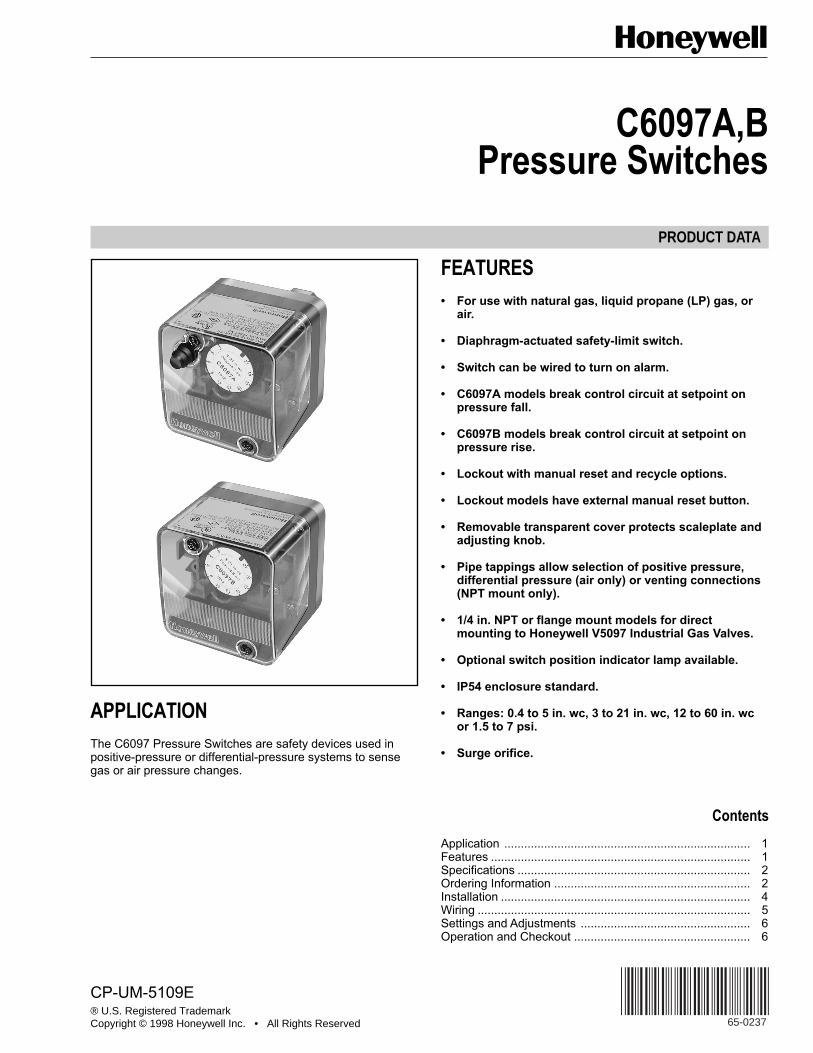
APPLICATIONThe C6097 Pressure Switches are safety devices used inpositive-pressure or differential-pressure systems to sensegas or air pressure changes.
FEATURES• For use with natural gas, liquid propane (LP) gas, or
air.
• Diaphragm-actuated safety-limit switch.
• Switch can be wired to turn on alarm.
• C6097A models break control circuit at setpoint onpressure fall.
• C6097B models break control circuit at setpoint onpressure rise.
• Lockout with manual reset and recycle options.
• Lockout models have external manual reset button.
• Pipe tappings allow selection of positive pressure,differential pressure (air only) or venting connections(NPT mount only).
• 1/4 in. NPT or flange mount models for directmounting to Honeywell V5097 Industrial Gas Valves.
• Optional switch position indicator lamp available.
• IP54 enclosure standard.
• Ranges: 0.4 to 5 in. wc, 3 to 21 in. wc, 12 to 60 in. wcor 1.5 to 7 psi.
• Surge orifice.
Contents
Application .......................................................................... 1Features .............................................................................. 1Specifications ...................................................................... 2Ordering Information ........................................................... 2Installation ........................................................................... 4Wiring .................................................................................. 5Settings and Adjustments ................................................... 6Operation and Checkout ..................................................... 6
CP-UM-5109E
C6097A,B PRESSURE SWITCHES
65-0237 2
ORDERING INFORMATION
When purchasing replacement and modernization products from your TRADELINE® wholesaler or distributor, refer to theTRADELINE® Catalog or price sheets for complete ordering number.
If you have additional questions, need further information, or would like to comment on our products or services, please write orphone:1. Your local Home and Building Control Sales Office (check white pages of your phone directory).2. Home and Building Control Customer Logistics
Honeywell Inc., 1885 Douglas Drive NorthMinneapolis, Minnesota 55422-4386 (612) 951-1000
In Canada—Honeywell Limited/Honeywell Limitée, 155 Gordon Baker Road, North York, Ontario M2H 3N7.International Sales and Service Offices in all principal cities of the world. Manufacturing in Australia, Canada, Finland, France,Germany, Japan, Mexico, Netherlands, Spain, Taiwan, United Kingdom, U.S.A.
SPECIFICATIONSModels:C6097A Pressure Switch: Breaks a circuit when pressure falls
to scale setting. See Table 1.C6097B Pressure Switch: Breaks a circuit when pressure
rises to scale setting. See Table 1.
Table 2 shows switch ratings and Table 3 shows alternateelectrical ratings when used with Honeywell Flame SafeguardProgrammers.
Minimum Ambient Temperature:5°F (-15°C).
Maximum Ambient Temperature:140°F (60°C).
Connections (Depending on Model):1/4-18 NPT tapping for main or high-pressure connection.1/8-27 NPT tapping for vent or low-pressure connection (air
only).Flange mount for connection to Honeywell V5097 Industrial
Gas Valves (internal vent only, no external connections).
Scale Range:0.4 to 5 in. wc (0.10 kPa to 1.25 kPa).3 to 21 in. wc (0.75 to 5.23 kPa).12 to 60 in. wc (3.0 kPa to 15 kPa).1.5 to 7 psi (10.3 kPa to 48 kPa).
Approvals:Underwriters Laboratories Inc. listed.Canadian Standards Association listed.Factory Mutual: Approved.Industrial Risk Insurers: Acceptable.CSD-1 AFB: Acceptable.
Accessories:32003041-001 C6097 Cover for manual reset models.32003040-001 C6097 Cover for recycle models.32003039-001 Position Indication Lamp Kit.
Dimensions:See Fig. 1 and 2.
Fig. 1. C6097 1/4 in. NPT Mount dimensions in in. (mm).
27/32 (22) HOLE
HOUSING
GAS CONNECTION 1/4 NPT WITH DUST SEAL
2-1/4(57)
3-3/16(81)
1-17/32(90)
2-21/32 (68)2-21/32 (68)
31/32(25)
25/32(21)
15/32 (12)1-3/32 (28)
13/32 (11)
2-23/32 (69)2-23/32 (69)
1-3/4 (45)
2-13/32(61)
DIFFERENTIALCONNECTION 1/8 NPT
INDICATOR
M17125
1 2 3
P
NO
NC
COM
TERMINAL DIAGRAM
C6097A,B PRESSURE SWITCHES
65-02373
Table 1. Pressure Switch Model Selection.
Manual Reset DifferentialNon-Manual Reset
Differential Maximum
Model
OperatingPressure
Range
Maximum atMinimumSetpoint
Maximumat
MaximumSetpoint Nominal Maximum
DifferentialType
RatedPressure
(continuous)(psi)
ManualReset Mediaa
SwitchAction atSetpoint Comments
C6097A1004 0.4 to 5 in.wc
— — 0.16 in.wc
0.24 in. wc Additive 2.9 No Air BreaksN.O. to
1/4 in. NPT Mount
C6097A1012 3 to 21 in.wc
2.4 in. wc 4.2 in. wc — — 4.3 Yes Air/Gas C.connec-
1/4 in. NPTMount
C6097A1020 3 to 21 in.wc
2.4 in. wc 4.2 in. wc — — 4.3 Yes Air/Gas tion onpressure
FlangeMount
C6097A1038 12 to 60 in.wc
10 in. wc 12 in. wc — — 4.8 Yes Air/Gas fall. 1/4 in. NPTMount
C6097A1046 12 to 60 in.wc
10 in. wc 12 in. wc — — 4.8 Yes Air/Gas FlangeMount
C6097A1053 3 to 21 in.wc
— 0.24 in.wc
0.48 in.wc 4.3 No Air/Gas 1/4 in. NPTMount
C6097A1061 3 to 21 in.wc
— — 0.24 in.wc
0.48 in. wc 4.3 No Air/Gas FlangeMount
C6097A1079 12 to 60 in.wc
— — 1.1 in. wc 2.4 in. wc 4.8 No Air/Gas 1/4 in. NPTMount
C6097A1087 12 to 60 in.wc
— — 1.1 in. wc 2.4 in. wc 4.8 No Air/Gas FlangeMount
C6097A1095 0.4 to 5 in.wc
0.6 in. wc 1.0 in. wc — — 2.9 Yes Air/Gas 1/4 in. NPTMount
C6097B1051 1.5 to 7 psi 1.1 psi 1.4 psi — — 21.0 Yes Air/Gas 1/4 in. NPTMount
C6097B1069 3 to 21 in.wc
— — 0.24 in.wc
0.48 in. wc 4.3 No Air/Gas FlangeMount
C6097B1077 12 to 60 in.wc
— — 1.1 in. wc 2.4 in. wc 4.8 No Air/Gas FlangeMount
C6097B1085 12 to 60 in.wc
— — 1.1 in. wc 2.4 in. wc 4.8 No Air/Gas 1/4 in. NPTMount
C6097B1093 1.5 to 7 psi — — 0.1 psi 0.3 psi 21.0 No Air/Gas FlangeMount
C6097B1101 1.5 to 7 psi — — 0.1 psi 0.3 psi 21.0 No Air/Gas 1/4 in. NPTMount
C6097B1119 3 to 21 in.wc
— — 0.24 in.wc
0.48 in. wc 4.3 No Air/Gas 1/4 in. NPTMount
a Acceptable media: Natural gas, liquid propane (LP) gas, and air.
C6097A,B PRESSURE SWITCHES
65-0237 4
Table 2. Switch Ratings (Amperes).
Table 3. Alternate Electrical Ratings when used withHoneywell Flame Safeguard Programmers.
Fig. 2. C6097 Flange Mount dimensions in in. (mm).
INSTALLATION
WARNINGExplosion or Fire Hazard.Can cause severe personal injury, death orproperty damage.Observe all safety requirements each time a control isinstalled on a burner.
When Installing this Product...1. Read these instructions carefully. Failure to follow them
can damage the product or cause a hazardouscondition.
2. Check the ratings given in the instructions and on theproduct to make sure that the product is suitable foryour application.
3. Installer must be a trained, experienced servicetechnician.
4. After installation is completed, check out productoperation as provided in these instructions.
WARNINGElectrical Shock Hazard.Can cause serious personal injury or death.Disconnect power supply before beginninginstallation. More than one disconnection can beinvolved.
Mounting
NOTE: On flange models, remove the label holding theO-ring in place and make sure O-ring seal is in placebefore mounting the pressure switch on the valve.
The C6097 models allow NPT or flange (directly to valve)mounting. The NPT models have a hexagonal fitting with a1/4 in. NPT tapping, which is the high pressure connection, indifferential applications. The bleed fitting is 1/8 in. NPTtapped. In differential pressure control applications using aironly, connect the lower pressure to the bleed fitting. See Fig.1 and Table 1. In applications using combustible gases, ventthe bleed tapping according to applicable standard code orjurisdictional authority.
C6097 models with flange mount can be fitted directly toHoneywell V5097 Industrial Gas Valves (model specific). SeeFig. 2 and Table 1. The flange mount models vent internally,with no external tap.
Mount the C6097A,B in any position.
Leak CheckAfter installation, perform a leak check on the pressureswitch:
1. Turn on main gas. Make sure gas has reached thepressure switch (e.g., high gas pressure switch)
2. Check installation for gas leaks using a gas leakdetector or a soap solution.
27/32 (22) HOLE
PRESSURE INLET
5/8 (16)
2-1/4(57)
2(52)
2 (52)
1-1/4(32)
1/32 (1)
2-21/32 (68)
2-23/32 (69)
2-23/32 (69)
INDICATOR
M17124
1 2 3
P
NO
NC
COM
TERMINAL DIAGRAM
120/240 Vac, 50/60 Hz
Inductive Full Load 3.0
Locked Rotor 18.0
Resistive 5.0
Device Rating
Ignition Transformer 540 VA
Pilot Valve 50 VA
Main Valve 400 VA with 2-1/2 times inrush.
C6097A,B PRESSURE SWITCHES
65-02375
WIRING
WARNINGElectrical Shock Hazard.Can cause serious personal injury or death.Disconnect power supply before beginninginstallation. More than one disconnection can beinvolved.
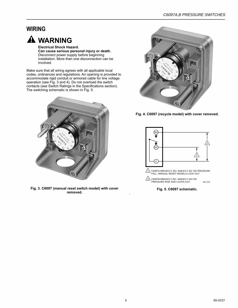
Make sure that all wiring agrees with all applicable localcodes, ordinances and regulations. An opening is provided toaccommodate rigid conduit or armored cable for line voltageoperation (see Fig. 3 and 4). Do not overload the switchcontacts (see Switch Ratings in the Specifications section).The switching schematic is shown in Fig. 5.
Fig. 3. C6097 (manual reset switch model) with coverremoved.
Fig. 4. C6097 (recycle model) with cover removed.
1
1
2
2
NO
NC
C
C6097A BREAKS C-NO, MAKES C-NC ON PRESSURE FALL. MANUAL RESET MODELS LOCK OUT.
C6097B BREAKS C-NC, MAKES C-NO ON PRESSURE RISE AND LOCKS OUT. M17123
Fig. 5. C6097 schematic..
C6097A,B PRESSURE SWITCHES
65-0237 6
SETTINGS AND ADJUSTMENTS
Pressure Setpoint AdjustmentTo adjust the pressure setting, turn the setpoint adjustmentdial (Fig. 3, 4 and 5) clockwise to increase the pressuresetting and counterclockwise to decrease the pressuresetting.
OPERATION AND CHECKOUT
OperationThe manual reset C6097A diaphragm actuates the snap-acting switch to break a control circuit and lock out whenpressure falls to the scale setting. The recycle C6097Amodels recycle automatically when the control circuit returnsto scale setting plus differential.
The manual reset C6097B diaphragm actuates the snap-acting switch that breaks a control circuit and locks out whenthe pressure rises to the scale setting. The recycle C6097Bmodels recycle automatically when the control pressure fallsto the scale setting minus differential.
Manual ResettingThe C6097A manual reset models lock out when pressurefalls to the scale setting and require manual resetting after thepressure rises to scale setting plus differential to resumenormal operation.
The C6097B manual reset models lock out when pressurerises to the scale setting and require manual resetting afterthe pressure falls to scale setting minus the differential toresume normal operation.
To reset, once normal operating pressure is restored, pushthe reset button in as far as it goes, then release.
IMPORTANTLockout models cannot be made to recycleautomatically by permanently holding in the resetlever.
CheckoutC6097 Gas or Air Switch
1. Set cutoff pressure.2. Open main supply line. Depress reset lever on lockout
models until switch makes control circuit.3. Set controller and limit switch to call for heat.4. For C6097A: Close the manual gas shutoff valve.
C6097 should open control circuit when pressurereaches cutoff point.For C6097B: Open the manual gas shutoff valve, wait afew minutes for the pressure to rise; then lower thescale setting until the switch breaks control circuit andlocks out.
5. For C6097A: Open the shutoff valve, return thepressure switch to its original setting and press thereset button (if necessary).For C6097B: raise setting to normal and press resetbutton (if necessary).
6. Allow system to operate through at least one completecycle to make sure all components are functioningproperly.
C6097A Air Switch Only1. Set cutoff pressure.2. Turn on fan.3. Block fan inlet or filter area. Switch should break control
circuit when pressure drops to cutoff point. Manualreset models lock out.
4. Remove obstruction. Press reset lever (manual resetmodels) and allow system to operate through at leastone complete cycle to be sure all components arefunctioning properly.
C6097A,B PRESSURE SWITCHES
65-02377
C6097A,B PRESSURE SWITCHES
65-0237 8
Honeywell Europe S.A.3 Avenue du Bourget1140 BrusselsBelgium
Honeywell Asia Pacific Inc.Room 3213-3225Sun Hung Kai CentreNo. 30 Harbour RoadWanchaiHong Kong
Home and Building ControlHoneywell Limited-Honeywell Limitée155 Gordon Baker RoadNorth York, OntarioM2H 3N7
Honeywell Latin American Region480 Sawgrass Corporate ParkwaySuite 200Sunrise FL 33325
65-0237 G.R. 12-98
Home and Building ControlHoneywell Inc.Honeywell PlazaP.O. Box 524Minneapolis MN 55408-0524
Printed in U.S.A. on recycled paper containing at least 10% post-consumer paper fibers. www.honeywell.com


![~g Lr# G *Ññ ãˆr#™Ì 1 Ññ - Deoband · LZÐœÓZKZäV,ZÔ¸Õ@»šMF,ŒÆ{Š%vZgâ~z0+» äV,ZÐ=ÂÅ]+Z[ gvZX ‰™h+zYï0+ix *CZŠp gzZ H×zgx *»',»Z Å yZ~„Vß‚ðZ’Z](https://static.documents.pub/doc/80x56/5d3c040b88c993d64f8c2e9d/g-lr-g-nn-ari-1-nn-lzdoeozkzaevzoosmfoeasvzgaz0.jpg)


