56
Product Guide 2009
Product Guide 2009
PI0418Fe_9571119_ProductGuide_2009_engl.indd 1 22.4.2009 09:36:25

- Reflex - Factory Ahlen
Reflex – You can depend on us!
The Reflex brand name is well known in Europe and throughout the world as a major leader in pressure control technology for heating, chilled and potable water applications. Our world wide growth has allowed us to build several state-of-the-art manufacturing facilities supplying the industry with outstanding quality products.Reflex Winkelmann GmbH + Co. KG having its headquarters in the Westfalian city of Ahlen is not only a recognized leader in expansion vessels but also a significant manufacturer of advanced system solutions such as compressor and pump-controlled pressurization systems, automatic air separation systems and hot water heaters.
Reflex has achieved its significant global growth today thanks to the unique combination of its world-class manufacturing skills, dedication to high-product quality at an affordable price and its commitment to continuous technical training of its people, our most precious resource. Our tradition goes back to 1898. This family oriented company started its core business in the elaboration of steel. A business in which we are recognised leaders today. The Heinrich Winkelmann Group form the parent company to a whole group of diversified manufacturing companies serving the heating segment and the whole automotive industry with over 2.000 employees. A tradition of more than a hundred years in this business makes us real experts today.
2
- Reflex - Factory Wabrzezno
PI0418Fe_9571119_ProductGuide_2009_engl.indd 2 22.4.2009 09:36:34

3
reflex ’V Intermediate vessel’ 34reflex ’EB Dirt collector’, reflex ’LA Air separator’, reflex ’T Expansion trap’ 35 reflex ’Water shock arrestor’, reflex ’Digital pressure gauge’ 36
reflex Accessories
Your Reflex export help team 52Reflex International 53Notes 55
About Reflex
Pressurization systems Page
Heat exchangers & hot water heatersreflex ’longtherm’ 37 - 41reflex ’longtherm’ - Sizing chart 42reflex ’Buffer tank’ 43 - 46reflex ’Hot water heater’ 48reflex ’Solar hot water heater’ 49reflex ’Hot water storage tank’ 50Accessories and spare parts for reflex ’Hot water heaters’ 50 - 51
Expansion vesselsfor heating, cooling and solar applications’reflex NG and N’ 4’reflex S’ 5’reflex G’ 6’reflex G’ - Accessories for bladder type expansion vessels 7’reflex F’ 8’reflex EN’ 8
Pressure vesselsfor potable water applications’refix DE’ 9 - 11’refix DE junior’ and ’refix HW’ 12’refix DD’ + Accessories for bladder type pressure vessels 13 ’refix DT5’ 14 - 17’refix’ - Sizing chart 18
Pressurization systemsreflex ’reflexomat’ compressor-controlled 20 - 22reflex ’minimat’ compressor-controlled 23reflex ’variomat’ pump-controlled 24 - 26reflex ’gigamat’ pump-controlled 27 - 28
reflex ’fillset’ 30reflex ’magcontrol’ 30reflex ’fillcontrol’ 30reflex ’Solenoid valve with ball valve’ 31reflex ’control P’ 31reflex ’servitec magcontrol’ 32reflex ’servitec levelcontrol’ 33
Make-up units & deaeration systems
Content
PI0418Fe_9571119_ProductGuide_2009_engl.indd 3 22.4.2009 09:36:35

Type Article-No. Weight Product-group
Qpp* Ø D H h Cred white kg mm mm mm
NG 8 7230100 7230107 1.7 10 96 206 285 --- R ¾NG 12 7240100 7240107 2.3 10 72 280 275 --- R ¾NG 18 7250100 7250107 2.8 10 56 280 345 --- R ¾NG 25 7260100 7260107 3.5 10 42 280 465 --- R ¾NG 35 7270100 7270107 5.7 10 24 354 460 130 R ¾NG 50 7001000 7001100 7.5 11 24 409 493 175 R ¾NG 80 7001200 7001300 9.9 11 12 480 565 175 R 1NG 100 7001400 7001500 11.2 11 10 480 670 175 R 1NG 140 7001600 7001700 14.5 11 8 480 912 175 R 1
N 200 7213300 --- 36.7 18 4 634 760 205 R 1N 250 7214300 --- 45.0 18 --- 634 890 205 R 1N 300 7215300 --- 52.0 18 --- 634 1060 235 R 1N 400 7218000 --- 65.0 18 --- 740 1070 245 R 1N 500 7218300 --- 79.0 18 --- 740 1290 245 R 1N 600 7218400 --- 85.0 18 --- 740 1530 245 R 1N 800 7218500 --- 103.0 18 --- 740 1995 245 R 1N 1000 7218600 --- 120.0 18 --- 740 2410 245 R 1
6 bar / 120 °C
6 bar / 120 °C
Vn Nominal volume [Litres]
’reflex’ Diaphragm type expansion vesselsfor heating, cooling and solar applications
4
8 - 25 Litres 35 - 250 Litres 300 - 1000 Litres
Ø D
H
h
C
Ø D
Ø D
HH
C
h
C
reflex ’Wall hung holder’ for vessels 8 - 25 litres
’reflex NG and N’
for heating and chilled water applicationsthreaded connectionsnon-replaceable diaphragm,according to DIN 4807 norm part 3,max. operating temperature 70 °Cmeets or exceeds EC norms for pressure vessels 97/23/CEcolour: red or white, durable powder coating finishpreset pressure 1.5 bar (Nitrogen)
* = Quantity per pallet** = Quantity per carton
Article-No. Product Qpc**group
8 - 25 l 7611000 75 36
bracket with tightening strap for vertical mounting
Article-No. Productgroup
8 - 25 l 7612000 75
holder with multiple connections
280
95 95 30
40
DN 32
Connection forexpansion pipe Rp ¾
Connection for filling Rp ½
Connection for manometer Rp ⅜
Connection for air-vent Rp ⅜
PI0418Fe_9571119_ProductGuide_2009_engl.indd 4 22.4.2009 09:36:40

2 - 33 Litres 50 - 250 Litres 300 - 600 Litres
Diaphragm type expansion vesselsfor heating, cooling and solar applications ’reflex’
Type Article-No. Weight Product-group
Qpp* Ø D H h C Pre-set pressurered white kg mm mm mm bar
S 2 9707700 --- 1.1 14 280 132 260 --- G ¾ 0.5S 8 9703900 9702600 2.5 14 96 206 325 --- G ¾S 12 9704000 9702700 3.5 14 72 280 300 --- G ¾S 18 9704100 9702800 4.5 14 56 280 380 --- G ¾ 1.5S 25 9704200 9702900 5.5 14 42 280 500 --- G ¾S 33 9706200 9706300 6.3 14 24 354 450 --- G ¾
10 bar / 120 °C
S 50 7209500 --- 13.2 19 20 409 469 168 R ¾S 80 7210300 --- 18.4 19 12 480 538 166 R 1S 100 7210500 --- 22.7 19 10 480 644 166 R 1S 140 7211500 --- 29.0 19 --- 480 886 166 R 1S 200 7213400 --- 40.0 19 --- 634 760 205 R 1 3.0S 250 7214400 --- 48.0 19 --- 634 890 205 R 1S 300 7215400 --- 54.0 19 --- 634 1060 235 R 1S 400 7219000 --- 78.0 19 --- 740 1070 245 R 1S 500 7219100 --- 80.0 19 --- 740 1290 245 R 1S 600 7219200 --- 103.0 19 --- 740 1530 245 R 1
Vn Nominal volume [Litres]
* = Quantity per pallet
5
Ø D
H
h
C
Ø D
Ø D
H H
h
C
C
reflex ’Digital pressure gauge’reflex ’SU Check valve’
for solar, heating and chilled water applicationssuitable for anti-frost substance up to 50%threaded connectionsnon-replaceable diaphragm,according to DIN 4807 norm part 3,max. operating temperature 70 °C33 litres with wall-hung clipmeets or exceeds EC norms for pressure vessels 97/23/CEcolour: red or white, durable powder coating finish
’reflex S’
display range up to approximately 9 barpressure indication in bar, kPa, psi
Article-No. Productgroup
9119198 86
shut-off device for inspection and removal of expansion vessels including dischargeaccording to DIN EN 12828PN 10 / 120 °C
’SU’ R ¾ x ¾
Automaticallyclosing coupling whendisconnected
’SU’ R 1 x 1
Vessel coupling connectionprotected shut-off with sealed cap
lock-sure valveDischarge
Discharge
PI0418Fe_9571119_ProductGuide_2009_engl.indd 5 22.4.2009 09:36:43

6
’reflex G’ - Options upon request
’reflex’ Bladder type expansion vesselsfor heating, cooling and solar applications
Type Article-No. Weight Product-group
Ø D H h Ckg mm mm mm
G 400 7521605 51.0 21 740 1253 146 G 1G 500 7521705 59.0 21 740 1473 146 G 1G 600 7522605 74.0 21 740 1718 146 G 1G 800 7523610 102.0 21 740 2183 146 G 1G 1000 Ø 740 7546605 158.0 21 740 2593 146 G 1G 1000 Ø 1000 7524605 248.0 22 1000 1975 305 DN 65/PN 6G 1500 7526605 297.0 22 1200 1975 305 DN 65/PN 6G 2000 7527605 370.0 22 1200 2430 305 DN 65/PN 6G 3000 7544605 640.0 22 1500 2480 335 DN 65/PN 6G 4000 7529605 828.0 22 1500 3055 335 DN 65/PN 6G 5000 7530605 905.0 22 1500 3590 335 DN 65/PN 6
G 100 7518000 16.5 21 480 856 152 G 1G 200 7518100 36.5 21 634 972 144 G 1¼G 300 7518200 41.6 21 634 1267 144 G 1¼G 400 7521005 59.0 21 740 1245 133 G 1¼G 500 7521006 65.1 21 740 1475 133 G 1¼G 600 7522006 128.0 21 740 1859 263 G 1½G 800 7523005 176.0 21 740 2324 263 G 1½G 1000 Ø 740 7546005 214.0 21 740 2604 263 G 1½G 1000 Ø 1000 7524005 355.0 22 1000 2000 290 DN 65/PN 16G 1500 7526005 410.0 22 1200 2000 290 DN 65/PN 16G 2000 7527005 505.0 22 1200 2450 290 DN 65/PN 16G 3000 7544005 870.0 22 1500 2580 320 DN 65/PN 16G 4000 7529005 1120.0 22 1500 3070 320 DN 65/PN 16G 5000 7530005 1330.0 22 1500 3610 320 DN 65/PN 16
6 bar / 120 °C
10 bar / 120 °C
Vn Nominal volume [Litres]
Article-No. Product-group
7945610 95
German TÜV factory test certification
’reflex G’ 100 - 5000 Litres
600 - 1000 (Ø 740) Litres 1000 (Ø 1000) - 5000 Litres(1000-2000 Litres zonder bovenste flens)
100 - 500 Litres
Ø D
H
C h
Ø D
H
Ø D
H
h Ch C
vessels > 5000 litresvessel operating pressure > 10 barflanged connections: DN 150 as an option for G 1000 - 5000 Ø 1000butyl bladder according to German DIN norm
’reflex G’
for heating and chilled water applicationsreplaceable bladder,according to DIN 4807 norm part 3,max. operating temperature 70 °Cmeets or exceeds EC norms for pressure vessels 97/23/ECinspection openingfactory-mounted pressure gaugecolour: red, durable powder coating finishpreset pressure 3.5 bar (Nitrogen)
PI0418Fe_9571119_ProductGuide_2009_engl.indd 6 22.4.2009 09:36:47

Accessories ’reflex’
Type Article-No. Product-group
MBM II 7857700 86
7
Electrode,fitted on the vessel (factory-mounted)
Relay, to be wall-mounted
Installation example’reflex G’ with reflex ’fillcontrol’ - Pressurization and Water make-up
’reflex G’
Expansion vessels
→ p. 6
reflex ’AG’
Connection setreflex ’fillcontrol’
Water make-up unit → p. 30
Make-up watermax. 6 bar
for the signalling of diaphragm rupture in ’reflex G’consists of an electrode and electrode relay(factory-mounted) operates 230 V / 50 Hz supplythree terminal dry contactrecommended: 1 device for each vessel
reflex ’MBM II Diaphragm rupture detector’
Type Article-No. Product-group
1 9119204 801¼ 9119205 801½ 9119206 80
for quick installation and easy inspection of vesselincluding lock-sure isolation valve G ½ discharge valve with lose connection according to DIN EN 12828PN 16 / 120 °C
reflex ’AG Connection set’
Vessel couplingconnection
Discharge
Lock-sureisolation valve
Expansion line
PI0418Fe_9571119_ProductGuide_2009_engl.indd 7 22.4.2009 09:36:50

’reflex’ Bladder type expansion vesselsfor heating, cooling and solar applications
8
Vn Nominal volume [Litres]
Type Article-No. Weight Product-group
H Ø D B C Pre-set pressurekg mm mm mm bar
F 8 9600011 6.5 15 389 389 88 G ⅜ 0.75F 12 9600030 8.5 15 444 350 108 G ½F 15 9600040 9.0 15 444 350 134 G ¾ 1.0F 18 9600000 9.5 15 444 350 158 G ¾F 24 9600010 9.8 15 444 350 180 G ¾
3 bar / 120 °C
Vn Nominal volume [Litres]
Type Article-No. Weight Product-group
Qpp* Ø D H L B C Pre-set pressurekg mm mm mm mm bar
EN 8 7280000 2.5 17 96 280 287 163 52 R ½
1.0EN 12 7280100 4.0 17 60 354 361 168 64 R ½EN 18 7280200 4.6 17 48 354 367 222 76 R ¾EN 25 7280300 5.8 17 42 409 419 239 93 R ¾EN 35 7280400 7.3 17 24 480 457 240 97 R ¾EN 50 7280500 8.6 17 20 480 457 317 125 R ¾ 1.5EN 80 7280600 15.6 17 8 634 612 325 135 R ¾
3 bar / 120 °C
∅ D
C
L
H
B8 - 80 Litres
* = Quantity per pallet
8 Litres 12 - 24 Litres
H
C
HHH
C
B BØ D Ø D
’reflex F’
flat vessel for heating (built-in boiler applications)non-replaceable diaphragm,according to DIN 4807 norm part 3,max. operating temperature 70 °Cfrom 18 litres with wall-hung clipmeets or exceeds EC normsfor pressure vessels 97/23/CEcolour: white, stove enamelled finish
’reflex EN’
for heating and chilled water applicationssuitable for anti-frost substance up to 50%provided with suspension bracket for easy installationbutyl bladder according to DIN 4807 norm part 3,max. operating temperature 70 °Cmeets or exceeds EC normsfor pressure vessels 97/23/ECcolour: red, durable powder coating finish
PI0418Fe_9571119_ProductGuide_2009_engl.indd 8 22.4.2009 09:36:52

10 bar / 70 °C
Vn Nominal volume [Litres]
Type Article-No. Weight Product-group
Qpp** Ø D H h Ckg mm mm mm
DE 2 7200300 1.0 40 100 132 260 --- G ¾DE 8 7301000 1.8 40 96 206 320 --- G ¾DE 12 7302000 2.4 40 72 280 310 --- G ¾DE 18 7303000 2.8 40 56 280 380 --- G ¾DE 25 7304000 3.7 40 42 280 500 --- G ¾DE 33 7303900 6.6 40 24 354 455 --- G ¾DE 33* 7305500 11.0 40 24 354 520 65 G ¾
DE 60 7306400 14 42 --- 409 740 160 G 1DE 80 7306500 16 42 --- 480 730 150 G 1DE 100 7306600 19 42 --- 480 835 150 G 1DE 200 7306700 47 42 --- 634 970 145 G 1¼DE 300 7306800 53 42 --- 634 1270 145 G 1¼DE 400 7306850 70 42 --- 740 1245 135 G 1¼DE 500 7306900 79 42 --- 740 1475 135 G 1¼
DE 600 7306950 155 42 --- 740 1860 265 G 1½DE 800 7306960 195 42 --- 740 2325 265 G 1½DE 1000 Ø 740 7306970 228 42 --- 740 2604 265 G 1½
DE 1000 Ø 1000 7311405 418 44 --- 1000 2010 290 DN 65 / PN 16 DE 1500 7311605 528 44 --- 1200 2010 290 DN 65 / PN 16DE 2000 7311705 703 44 --- 1200 2470 290 DN 65 / PN 16 DE 3000 7311805 1043 44 --- 1500 2520 320 DN 65 / PN 16DE 4000 7354000 1120 44 --- 1500 3095 320 DN 65 / PN 16DE 5000 7354200 1330 44 --- 1500 3630 320 DN 65 / PN 16
60 - 500 Litres
33 litreswith wall-hung clip
(back view)
2 - 25 Litres 33 Litres*
* = DE 33 Litres with feet** = Quantity per pallet
9
10 bar
Ø D
H
Ch
Ø D
H
Ch
1000 (Ø 1000) - 2000 Litres
Ø D
H
Ch
3000 - 5000 Litres
Ø D
Ch
H
Ø D
H
C
Ø D
H
Ch C
Ø D
H
600 - 1000 (Ø 740) Litres
Bladder type expansion vesselsPotable water, water heating & hydro-pneumatic well applications ’refix’
ACS’refix DE’
for potable water, water heating andhydro-pneumatic well applicationsbladder according to DIN 4807 norm part 3from 60 litres volume with replaceable bladderall vessel parts in contact with water are coated against corrosion meets or exceeds EC normsfor pressure vessels 97/23/ECfitted with manometer from Ø 1000 mmcolour: blue, durable powder coating finishpreset pressure 4.0 bar (Nitrogen)
vessels > 25 barvessels > 5000 litresbutyl-bladder according to German KTW-C norminner lining against corrosion according to German KTW-A (food stuff regulation)stainless steel connectionnon-standard flanged connections’MBM II Diaphragm rupture detector’ → p.11German TÜV factory test certificate according to EC norms for pressure vessels → p.11
’refix DE’ - Options upon request
PI0418Fe_9571119_ProductGuide_2009_engl.indd 9 22.4.2009 09:37:01

’refix’ Bladder type expansion vesselsPotable water, water heating & hydro-pneumatic well applications
10
Vn Nominal volume [Litres]
Type Article-No. Weight Product-group
Ø D H h Ckg mm mm mm
DE 8 7301006 2.0 40 206 320 --- G ¾DE 12 7302105 2.8 40 280 310 --- G ¾DE 25 7304015 4.2 40 280 500 --- G ¾
DE 80 7348600 24 42 480 730 150 G 1DE 100 7348610 27 42 480 835 150 G 1DE 200 7348620 54 42 634 970 145 G 1¼DE 300 7348630 63 42 634 1270 145 G 1¼
DE 400 7348640 111 42 740 1395 265 G 1½DE 500 7348650 123 42 740 1615 265 G 1½DE 600 7348660 167 42 740 1860 265 G 1½DE 800 7348670 217 42 740 2325 265 G 1½DE 1000 Ø 740 7348680 252 42 740 2604 265 G 1½
DE 1000 Ø 1000 7312805 519 44 1000 2010 290 DN 65 / PN 16DE 1500 7312905 674 44 1200 2030 290 DN 65 / PN 16DE 2000 7313005 884 44 1200 2500 290 DN 65 / PN 16DE 3000 7313105 1229 44 1500 2570 320 DN 65 / PN 16DE 4000 7354100 1344 44 1500 3145 320 DN 65 / PN 16DE 5000 7354300 1596 44 1500 3680 320 DN 65 / PN 16
16 bar / 70 °C
8 - 25 Litres 80 - 500 Litres 600 - 1000 (Ø 740) Litres
16 bar
Ø D
H
C
3000 - 5000 Litres
Ø D
Ch
1000 (Ø 1000) - 2000 Litres
Ø D
H
Ch
Ø D
H
Ch
H
Ø D
H
Ch
ACS
vessels > 25 barvessels > 5000 litresbutyl-bladder according to German KTW-C norminner lining against corrosion according to German KTW-A (food stuff regulation)stainless steel connectionnon-standard flanged connections’MBM II Diaphragm rupture detector’ → p.11
’refix DE’ - Options upon request
German TÜV factory test certification
’refix DE’ 80 - 5000 litres
Article-No. Productgroup
7945610 95
PI0418Fe_9571119_ProductGuide_2009_engl.indd 10 22.4.2009 09:37:04

Vn Nominal volume [Litres]
Type Article-No. Weight Product-group
Ø D H h Ckg mm mm mm
DE 8 7290100 3.5 40 206 320 --- G ¾
DE 80 7317600 95 44 450 925 185 DN 50 / PN 40DE 120 7313700 130 44 450 1235 185 DN 50 / PN 40DE 180 7313500 167 44 450 1515 185 DN 50 / PN 40DE 300 7313800 189 44 750 1275 200 DN 50 / PN 40DE 400 7313300 290 44 750 1395 200 DN 50 / PN 40DE 600 7321500 392 44 750 1860 185 DN 50 / PN 40DE 800 7321200 466 44 750 2260 185 DN 50 / PN 40DE 1000 Ø 750 7321000 547 44 750 2760 185 DN 50 / PN 40DE 1000 Ø 1000 7322200 674 44 1000 1980 210 DN 65 / PN 40DE 1500 7322100 876 44 1200 2050 285 DN 65 / PN 40DE 2000 7313400 1149 44 1200 2500 285 DN 65 / PN 40DE 3000 7345700 1597 44 1500 2520 315 DN 65 / PN 40
25 bar / 70 °C
11
25 bar
Ø D
8 Litres 80 - 1000 (Ø 750) Litres
Ø D
H
C
h
H
C3000 Litres
Ø D
Ch
1000 (Ø 1000) - 2000 Litres
Ø D
H
Ch
H
Bladder type expansion vesselsPotable water, water heating & hydro-pneumatic well applications ’refix’
ACS
’refix DE’ - Options upon request
vessels > 25 barflanged connections: DN 65 and DN 80butyl-bladder according to German KTW-C norminner lining against corrosion according to German KTW-A (food stuff regulation)German TÜV factory test certification
for the signalling of diaphragm rupture in ’reflex DE’ 60 ltr and aboveconsists of an electrode and electrode relay (factory-mounted)
operates 230 V / 50 Hz supplythree terminal dry contactrecommended: 1 device for each vessel
reflex ’MBM II Diaphragm rupture detector’
Electrode,fitted on the vessel (factory-mounted)
Relay, to be wall-mounted
Type Article-No. Productgroup
MBM II 7857700 86
PI0418Fe_9571119_ProductGuide_2009_engl.indd 11 22.4.2009 09:37:06

’refix’ Diaphragm type expansion vesselsPotable water & hydro-pneumatic well applications
10 bar / 70 °C
Vn Nominal volume [Litres]
Type Article-No. Weight Product-group
Ø D H h C Pre-set pressurekg mm mm mm bar
DE junior 25 7200400 4.7 54 280 485 --- G 1 2.0DE junior 50 7309600 13.2 54 409 605 115 R 1
4.0
DE junior 80 7309700 18.4 54 480 665 105 R 1DE junior 100 7309800 22.7 54 480 770 105 R 1DE junior 140 7309900 29.0 54 480 1015 105 R 1DE junior 200 7363500 40.0 54 634 885 90 R 1DE junior 300 7363600 54.0 54 634 1185 90 R 1DE junior 400 7363700 78.0 54 740 1175 80 R 1DE junior 500 7363800 80.0 54 740 1390 80 R 1DE junior 600 7363900 103.0 54 740 1630 75 R 1
Ø D
H
12
50 - 400 Litres 500 - 600 Litres
hh
Ø D
H
C
Ø D
H
CC
25 Litres
10 bar / 70 °C
Vn Nominal volume [Litres]
Type Article-No. Weight Product-group
Qpp* Ø D H L L2 W2 W Ckg mm mm mm mm mm mm
HW 25 7200200 5.6 49 36 280 294 484 228 214 270 G 1HW 50 7308805 15.0 49 20 409 434 492 175 285 350 G 1HW 80 7200260 18.0 49 --- 480 504 562 193 285 350 G 1HW 100 7200250 21.0 49 --- 480 504 667 303 285 350 G 1
* = Quantity per pallet
H
Ø D
WW2
LL2
C
∅ 86
115
G ½
ACS
ACS
’refix DE junior’
for potable water, fire fighting andhydro-pneumatic well applicationsnon-replaceable diaphragm,according to DIN 4807 norm part 3,max. operating temperature 70 °Call vessel parts in contact with water are coated against corrosionmeets or exceeds EC normsfor pressure vessels 97/23/ECcolour: blue, durable powder coating finish
’refix HW’
for potable water, fire fighting and hydro-pneumatic well applicationsnon-replaceable diaphragm, according to DIN 4807 norm part 3, max. operating temperature 70 °Call vessel parts in contact with water are coated against corrosionmeets or exceeds EC norms for pressure vessels 97/23/ECcolour: blue, durable powder coating finishpreset pressure 2.0 bar (Nitrogen)
Article-No. Productgroup
7351000 7410 bar / 70 °C
reflex ’Water shock arrestor’
to be used along devices where sudden pressure build-up is caused by quick shut-off such as washing machines, dish washers etc.meets or exceeds EC normsfor pressure vessels 97/23/EC volume 165 cm³preset pressure 4 barcolour: blue, durable powder coating finish
PI0418Fe_9571119_ProductGuide_2009_engl.indd 12 22.4.2009 09:37:08

Bladder type expansion vesselsPotable water, water heating & hydro-pneumatic well applications ’refix’
13
ACS
ACS
Vn Nominal volume [Litres]
10 bar / 70 °C
25 bar / 70 °C
Type Article-No. Weight Product-group
Qpp* Ø D H Agroen white kg mm mm
DD 8 7308000 7307700 1.9 48 96 206 335 G ¾DD 12 7308200 7307800 2.3 48 72 280 325 G ¾DD 18 7308300 7307900 2.8 48 56 280 395 G ¾DD 25 7308400 7380400 3.7 48 42 280 515 G ¾DD 33 7380700 7380800 6.6 48 24 354 465 G ¾
DD 8 7290200 7290300 9.0 48 --- 206 335 G ¾
* = Quantity per pallet
33 litreswith wall-hung clip
(back view)
8 - 25 Litres
T-piece Rp ¾ included(for ’DD 8 - 33l’)
Ø D
A
Ø D
H
A
H
’refix DD’
for potable water applications according to DIN/DVGW 4807 norm part 5integrated internal circulation / anti-legionellabutyl bladder according to German KTW-C normmeets or exceeds EC normsfor pressure vessels 97/23/ECgreen or white inner and outer anti-corrosion coating according to German KTW-A (food stuff regulation)preset pressure 4.0 bar (Nitrogen)can be installed with ’flowjet’ - flow through valve
** delivery in package containing 5 pieces
Type Article-No. Product Qpp*group**
fl owjet ¾ 9116799 85 5
for easy assembly and maintenance of ’refix DD’ pressure tanks according to DIN/DVGW 4807 norm part 5 max. operating pressure 16 barmax. operating temperature 70 °Cconnectable to T-piece Rp ¾ (included in ’refix DD’ delivery)
’flowjet’ - Flow through, shut-off and discharge valve
’refix’ - Accessories
reflex ’Wall hung holder’ for vessels 8 - 25 litres
bracket with tightening strap for vertical mounting
’flowjet’on-site installation
Scope ofdelivery
’refix DD’
T-piece
Type Article-No. Product Qpc*group
8 - 25 l 7611000 75 36
* = Quantity per carton
PI0418Fe_9571119_ProductGuide_2009_engl.indd 13 22.4.2009 09:37:11

10 bar / 70 °CType Connection Article-No. Weight Product-
groupØ D H h
C kg mm mm mmDT5 60 ’fl owjet’ Rp 1 ¼ 7309000 15 47 409 766 80
DT5 80 ’fl owjet’ Rp 1 ¼ 7309100 17 47 480 750 65DN 50 / PN 16 7365000 23 47 480 750 100DN 65 / PN 16 7335705 24 47 480 750 110DN 80 / PN 16 7335805 26 47 480 750 115
DT5 100 ’fl owjet’ Rp 1 ¼ 7309200 20 47 480 835 65DN 50 / PN 16 7365400 26 47 480 835 100DN 65 / PN 16 7365405 27 47 480 835 110DN 80 / PN 16 7365406 29 47 480 835 115
DT5 200 ’fl owjet’ Rp 1 ¼ 7309300 47 47 634 975 80DN 50 / PN 16 7365100 53 47 634 975 105DN 65 / PN 16 7365105 54 47 634 975 115DN 80 / PN 16 7365106 57 47 634 975 120
DT5 300 ’fl owjet’ Rp 1 ¼ 7309400 53 47 634 1275 80DN 50 / PN 16 7365200 59 47 634 1275 105DN 65 / PN 16 7336305 60 47 634 1275 115DN 80 / PN 16 7336405 63 47 634 1275 120
DT5 400 ’fl owjet’ Rp 1 ¼ 7319305 73 47 740 1245 70DN 50 / PN 16 7365500 79 47 740 1245 95DN 65 / PN 16 7336505 80 47 740 1245 105DN 80 / PN 16 7336605 83 47 740 1245 110
DT5 500 ’fl owjet’ Rp 1 ¼ 7309500 79 47 740 1475 70DN 50 / PN 16 7365300 85 47 740 1475 90DN 65 / PN 16 7365307 86 47 740 1475 100DN 80 / PN 16 7365305 89 47 740 1475 110
Vn Nominal volume [Litres]
’refix’ Bladder type expansion vesselsPotable water, water heating & hydro-pneumatic well applications
14
10 bar
1000 (Ø 1000) - 2000 Litres 3000 Litres
H
Ch
60 - 500 Litres
Ø D
600 - 1000 (Ø 740) Litres
Ø D
Ø D
Ø D
HH
H
hhh CCC
ACS’refix DT5’
for potable water applications according to DIN/DVGW 4807 norm part 5integrated internal circulation / anti-legionellain case of Rp 1¼ connection (60 - 500 litres) factory-equipped with ’flowjet’: flow-through, shut-off and discharge valvereplaceable butyl bladder according to German KTW-C normgreen inner and outer anti-corrosion coating according to German KTW-A (food stuff regulation)meets or exceeds EC norms for pressure vessels 97/23/ECpreset pressure 4.0 bar (Nitrogen)
PI0418Fe_9571119_ProductGuide_2009_engl.indd 14 22.4.2009 09:37:13

Bladder type expansion vesselsPotable water, water heating & hydro-pneumatic well applications ’refix’
Type Connection Article-No. Weight Product-group
Ø D H hC kg mm mm mm
DT5 600 DN 50 / PN 16 7365600 164 47 740 1860 235DN 65 / PN 16 7336705 165 47 740 1860 235DN 80 / PN 16 7336806 168 47 740 1860 235
DT5 800 DN 50 / PN 16 7365700 204 47 740 2325 235DN 65 / PN 16 7336905 205 47 740 2325 235DN 80 / PN 16 7337006 208 47 740 2325 235
DT5 1000 Ø 740 DN 50 / PN 16 7365800 244 47 740 2604 235DN 65 / PN 16 7337105 245 47 740 2604 235DN 80 / PN 16 7337205 248 47 740 2604 235
DT5 1000 Ø 1000 DN 65 / PN 16 7320105 424 46 1000 2000 160DN 80 / PN 16 7337305 426 46 1000 2000 150DN 100 / PN 16 7337405 428 46 1000 2000 140
DT5 1500 DN 65 / PN 16 7320305 539 46 1200 2000 160DN 80 / PN 16 7337505 541 46 1200 2000 150DN 100 / PN 16 7337605 543 46 1200 2000 140
DT5 2000 DN 65 / PN 16 7320505 714 46 1200 2450 160DN 80 / PN 16 7337705 716 46 1200 2450 150DN 100 / PN 16 7337805 718 46 1200 2450 140
DT5 3000 DN 65 / PN 16 7320705 714 46 1500 2520 190DN 80 / PN 16 7337905 716 46 1500 2520 180DN 100 / PN 16 7338005 718 46 1500 2520 170
Vn Nominal volume [Litres]
10 bar / 70 °C
15
Electrode,fitted on the vessel (factory-mounted)
Relay, to be wall-mounted
for the signalling of diaphragm rupture in ’reflex DT5’consists of an electrode and electrode relay(factory-mounted)
operates 230 V / 50 Hz supplythree terminal dry contactrecommended: 1 device for each vessel
reflex ’MBM II Diaphragm rupture detector’
’refix DT5’ - Options upon request
vessels > 16 barstainless steel connections
German TÜV factory test certification
’refix DT5’
Type Article-No. Productgroup
MBM II 7857700 86
Article-No. Productgroup
7945610 95
PI0418Fe_9571119_ProductGuide_2009_engl.indd 15 22.4.2009 09:37:17

’refix’ Bladder type expansion vesselsPotable water, water heating & hydro-pneumatic well applications
Vn Nominal volume [Litres]
Type Connection Article-No. Weight Product-group
Ø D H hC kg mm mm mm
DT5 80 ’fl owjet’ Rp 1 ¼ 7316005 27 47 480 750 65DN 50 / PN 16 7370000 32 47 480 750 100 DN 65 / PN 16 7310306 33 47 480 750 110DN 80 / PN 16 7310307 35 47 480 750 115
DT5 100 ’fl owjet’ Rp 1 ¼ 7365408 29 47 480 835 65DN 50 / PN 16 7370100 34 47 480 835 100 DN 65 / PN 16 7370101 35 47 480 835 110DN 80 / PN 16 7370102 37 47 480 835 115
DT5 200 ’fl owjet’ Rp 1 ¼ 7365108 55 47 634 975 80DN 50 / PN 16 7370200 61 47 634 975 105DN 65 / PN 16 7370205 62 47 634 975 115DN 80 / PN 16 7370206 65 47 634 975 120
DT5 300 ’fl owjet’ Rp 1 ¼ 7319205 64 47 634 1275 80DN 50 / PN 16 7370300 70 47 634 1275 105DN 65 / PN 16 7314205 71 47 634 1275 115DN 80 / PN 16 7314206 74 47 634 1275 120
DT5 400 DN 50 / PN 16 7370400 118 47 740 1395 235DN 65 / PN 16 7339006 119 47 740 1395 235DN 80 / PN 16 7339005 122 47 740 1395 235
DT5 500 DN 50 / PN 16 7370500 130 47 740 1620 235DN 65 / PN 16 7370507 131 47 740 1620 235DN 80 / PN 16 7370505 134 47 740 1620 235
DT5 600 DN 50 / PN 16 7370600 174 47 740 1860 235DN 65 / PN 16 7339105 175 47 740 1860 235DN 80 / PN 16 7339205 178 47 740 1860 235
DT5 800 DN 50 / PN 16 7370700 224 47 740 2325 235DN 65 / PN 16 7339305 225 47 740 2325 235DN 80 / PN 16 7339406 228 47 740 2325 235
DT5 1000 Ø 740 DN 50 / PN 16 7370800 259 47 740 2604 235DN 65 / PN 16 7339505 260 47 740 2604 235DN 80 / PN 16 7339605 263 47 740 2604 235
16 bar / 70 °C
16
16 bar
1000 (Ø 1000) - 2000 Litres 3000 Litres
H
Ch
60 - 500 Litres
Ø D
600 - 1000 (Ø 740) Litres
Ø D
Ø D
Ø D
HH
H
hhh CCC
ACS
PI0418Fe_9571119_ProductGuide_2009_engl.indd 16 22.4.2009 09:37:19

Bladder type expansion vesselsPotable water, water heating & hydro-pneumatic well applications ’refix’
Type Connection Article-No. Weight Product-group
Ø D H hC kg mm mm mm
DT5 1000 Ø 1000 DN 65 / PN 16 7320205 530 46 1000 2000 160DN 80 / PN 16 7339705 533 46 1000 2000 150DN 100 / PN 16 7339805 536 46 1000 2000 140
DT5 1500 DN 65 / PN 16 7320405 685 46 1200 2000 160DN 80 / PN 16 7339905 688 46 1200 2000 150DN 100 / PN 16 7340005 691 46 1200 2000 140
DT5 2000 DN 65 / PN 16 7320605 895 46 1200 2450 160DN 80 / PN 16 7340105 898 46 1200 2450 150DN 100 / PN 16 7340205 901 46 1200 2450 140
DT5 3000 DN 65 / PN 16 7320805 1240 46 1500 2520 190DN 80 / PN 16 7340305 1243 46 1500 2520 180DN 100 / PN 16 7340405 1246 46 1500 2520 170
16 bar / 70 °C
Vn Nominal volume [Litres]
17
Electrode,fitted on the vessel (factory-mounted)
Relay, to be wall-mounted
for the signalling of diaphragm rupture in ’reflex DT5’consists of an electrode and electrode relay(factory-mounted)
operates 230 V / 50 Hz supplythree terminal dry contactrecommended: 1 device for each vessel
reflex ’MBM II Diaphragm rupture detector’
’refix DT5’ - Options upon request
vessels > 16 barstainless steel connections
German TÜV factory test certification
’refix DT5’
Type Article-No. Productgroup
MBM II 7857700 86
Article-No. Productgroup
7945610 95
PI0418Fe_9571119_ProductGuide_2009_engl.indd 17 22.4.2009 09:37:21

’refix’ Sizing chart
18
DT5 DT5
DD DD
Selection of the nominal vessel volume Vn
pa pSVVn
p0VSp
V10 °C Cold water inlet temperature
60 °C Storage temperature
psv / bar 6 8 10Vsp [Litres] Nominal volume ’refi x’ [litres]
90 8 8 8100 12 8 8120 12 8 8130 12 8 8150 18 8 8180 18 8 8200 18 12 8250 25 12 12300 25 18 12400 33 18 18500 60 25 18600 60 33 25700 60 33 25800 80 60 25900 80 60 33
1000 100 60 601500 200 80 602000 200 100 803000 300 200 100
psv / bar 6 8 10Vsp [Litres] Nominal volume ’refi x’ [litres]
90 8 8 8100 8 8 8120 8 8 8130 8 8 8150 8 8 8180 12 8 8200 12 8 8250 12 12 8300 18 12 12400 25 18 18500 25 18 18600 33 25 18700 33 25 25800 60 33 25900 60 33 25
1000 60 33 331500 80 60 602000 100 80 803000 200 100 100
Detailed information on calculation can be taken from our bro-chure "Pressurization, deaeration, water make-up, and heat trans-fer systems" and also from our sizing software "reflex 4.1" which is available on CD-ROM or can be downloaded at www.reflex.de.
Preset press. gas p0 = 3.0 barSet press. of the pa ≥ 3.2 barpressure reducer
Preset press. gas p0 = 4.0 bar = factory settingSet press. of the pa ≥ 4.2 barpressure reducer
PI0418Fe_9571119_ProductGuide_2009_engl.indd 18 22.4.2009 09:37:22

Pressurization systems
19
PI0418Fe_9571119_ProductGuide_2009_engl.indd 19 22.4.2009 09:37:23

reflex ’reflexomat’ Pressurization unitcompressor-controlled
20
RG basic vessel 200 - 800with control unit VS 90/1
RG basic vessel 1000 - 5000with control unit VS 150/1
Hg
H
Ø D
h
H
Ø D
hC
compressor-controlled pressurization system for heating and cooling systems up to 120 °C max. flow temperaturemaintains the pressure level within +/- 0.1 bar boundarymeets or exceeds EC normsfor pressure vessels 97/23/ECsuperior quality butyl bladder according to German DIN 4807 norm part 3,max. operating temperature 70 °Cmicroprocessor control with display in 8 languagespermanent display of system pressure and tank volume level230 V output for fully automated water make-up2 dry contacts(collective alarm, min. water level)
data output through RS-485 (not for VS 90/1)
reflex ’reflexomat’
Type Article-No. Weight Product H / W / Dkg group mm
up to 800 l / 6 barVS on theRG basic
vessel
VS 90/1* 7880100 21 33 415 / 395 / 520 Compressor in the VSVS 150/1 7880200 28 33 415 / 395 / 520VS 300/1 7880300 34 33 415 / 395 / 520
Compressor alongsideVS 400/1 7880400 51 33 415 / 395 / 520VS 580/1 7880500 102 33 415 / 395 / 520
350, 500750 l / 10 bar
and from1000 l VS
in front of theRG basic vessel
VS 90/1* 7880600 25 33 585 / 395 / 345 Compressor in the VSVS 150/1 7880700 32 33 585 / 395 / 345VS 300/1 7880800 38 33 585 / 395 / 345
Compressor alongsideVS 400/1 7880900 55 33 585 / 395 / 345VS 580/1 7881200 106 33 585 / 395 / 345
VS control unit with 1 compressor
** Voltage 230 V / 50 Hz; from VS 150: 400 V / 50 Hz
Operation of more than 2 compressors and tailor-made control panels upon request
Type Article-No. Weight Product H / W / Dkg group mm
up to 800 l / 6 barVS on theRG basic
vessel
VS 90/2** 7882100 33 33 415 / 395 / 520 1 Compressor in the VSVS 150/2 7883100 45 33 415 / 395 / 520 1 Compressor alongsideVS 300/2 7884100 61 33 415 / 395 / 520
2 Compressors alongsideVS 400/2 7885100 95 33 415 / 395 / 520VS 580/2 7886100 197 33 415 / 395 / 520
350, 500750 l / 10 bar
and from1000 l VS
in front of theRG basic vessel
VS 90/2** 7886200 37 33 585 / 395 / 345 1 Compressor in the VSVS 150/2 7886300 49 33 585 / 395 / 345 1 Compressor alongsideVS 300/2 7886400 65 33 585 / 395 / 345
2 Compressors alongsideVS 400/2 7886500 99 33 585 / 395 / 345VS 580/2 7886600 201 33 585 / 395 / 345
VS control unit with 2 compressors
Type Article-No. Weight Product H / W / Dkg group mm
until 800 l VS 90/1* 7881100 9 33 415 / 395 / 520 without compressorfrom 1000 l VS 90/1* 7881105 9 33 585 / 395 / 345* Voltage 230 V / 50 Hz
additional price for solenoid valve for the feed of oil-free, compressed air(fi tted ready for connection in the VS 90/1 control unit without compressor)
MV ¼ 7913000 35 ---
Control unit without compressor (for on-site air circuits)
* - Voltage 230 V / 50 Hz; from VS 150: 400 V / 50 Hz* - 1 dry contact (common fault)
PI0418Fe_9571119_ProductGuide_2009_engl.indd 20 22.4.2009 09:37:29

Options reflex ’reflexomat’
21reflex ’reflexomat’ - Options
RG Basic vessel
6 bar 10 barType Article-No. Weight Article-No. Weight Product Ø D H Hg h C
kg kg group mm mm mm mmRG 200 7799100 37 --- --- 30 634 970 1350 115 R 1RG 300 7799200 54 --- --- 30 634 1270 1650 115 R 1RG 400 7799300 65 --- --- 30 740 1255 1640 100 R 1RG 500 7799400 78 --- --- 30 740 1475 1860 100 R 1RG 600 7799500 94 --- --- 30 740 1720 2110 100 R 1RG 800 7799600 149 --- --- 30 740 2185 2570 100 R 1
RG 350 --- --- 7654000 230 30 750 1320 --- 200 DN 40RG 500 --- --- 7654100 275 30 750 1740 --- 200 DN 40RG 750 --- --- 7654200 345 30 750 2185 --- 200 DN 50
RG 1000 7650105 330 7651005 580 32 1000 2025 --- 195 DN 65RG 1500 7650305 465 7651205 800 32 1200 2025 --- 185 DN 65RG 2000 7650405 656 7651305 960 32 1200 2480 --- 185 DN 65RG 3000 7650605 795 7651505 1425 32 1500 2480 --- 220 DN 65RG 4000 7650705 1080 7651605 1950 32 1500 3065 --- 220 DN 65RG 5000 7650805 1115 7651705 2035 32 1500 3590 --- 220 DN 65
flanged connections: PN 6 at 6 bar, PN 16 at 10 bar for RG 800: one could choose to fix control unit on top of the tank (check total height) or use wall bracket → see below
Butylbladder
’reflexomat’ Total price ’reflexomat’ OptionsVS Control unit
RG Basic vessel= +
flanged connections: PN 6 at 6 bar, PN 16 at 10 bar easy installation of RF 200 - 800/6 bar with reflex ’AG Connection set’ → p. 7
RF Secondary vessel
6 bar 10 barType Article-No. Weight Article-No. Weight Product Ø D H h C
kg kg group mm mm mmRF 200 7789100 37 --- --- 30 634 970 155 R 1RF 300 7789200 54 --- --- 30 634 1270 155 R 1RF 400 7789300 65 --- --- 30 740 1255 140 R 1RF 500 7789400 78 --- --- 30 740 1475 140 R 1RF 600 7789500 94 --- --- 30 740 1720 140 R 1RF 800 7789600 149 --- --- 30 740 2185 140 R 1
RF 350 --- --- 7654300 230 30 750 1320 200 DN 40RF 500 --- --- 7654400 275 30 750 1740 200 DN 40RF 750 --- --- 7654500 345 30 750 2185 200 DN 40
RF 1000 7652005 330 7653005 580 32 1000 2025 305 DN 65RF 1500 7652205 465 7653205 800 32 1200 2025 305 DN 65RF 2000 7652305 656 7653305 960 32 1200 2480 305 DN 65RF 3000 7652505 795 7653505 1425 32 1500 2480 334 DN 65RF 4000 7652605 1080 7653605 1950 32 1500 3065 334 DN 65RF 5000 7652705 1115 7653705 2035 32 1500 3590 334 DN 65
21
Butylbladder
reflex ’Wall bracket’
for user-friendly installation of the VS 90 and VS 150 control units with RG 800 basic vessels (check overall height H/Hg)
including 3 m long connecting hoses
Article-No. Productgroup
7881900 35
RF Secondary vessel
(Option)
H
Ø D
C
h
PI0418Fe_9571119_ProductGuide_2009_engl.indd 21 22.4.2009 09:37:30

reflex ’reflexomat’ Options
RS-485 Interface for VS 90/1 control unit
for the connection of Reflex electronic modules like Master-Slave, Bus module, etc.incl. 2 dry contacts
Article-No. Code
for RG 200-800 l / 6 bar 7997710 33for RG 350 l and above 7997720 33
22
reflex ’MBM II Diaphragm rupture detector’
for the signalling of diaphragm rupture in ’reflexomat’ basic and secondary vesselsconsists of an electrode and electrode relay (factory-mounted) operates 230 V / 50 Hz supplythree terminal dry contactrecommended: 1 device for each vessel
Electrode,fitted on the vessel (factory-mounted)
Relay, to be wall-mounted
Type Article-No. Productgroup
MBM II 7857700 86
reflex ’Master-Slave control module’ (not for VS 90/1)
for the optimized operation of up to 10 ’reflexomat’ units in hydraulic interconnection at a distance of 1000 m and more (requires one module for each control unit)
Article-No. Productgroup
7859000 35
reflex ’RE Extension module’ (not for VS 90/1)
analog output 0–10 V/4 - 20 mA for pressure and level indication at distance, with 6 digital inputs and 6 floating outputsfor wall mounting including earthing type plug (230 V / 50 Hz)
Article-No. Productgroup
Standard parameters: according to instruction manual7858405 35
Special parameters: upon request
reflex ’RK Communication module’ (not for VS 90/1)
for the external operation of the control unit through a twin-core cable up to 1000 m range
Article-No. Productgroup
7951200 35
reflex ’Bus module’ (not for VS 90/1)
for exchange of data between the Reflex control unit and the building central control technology (BMS)
Type Article-No. Productgroup
’Lon Works’ Digital 7860000 86’Lon Works’ 7860100 86’Profi bus-DP’ 7860200 86’Ethernet’ 7860300 86
PI0418Fe_9571119_ProductGuide_2009_engl.indd 22 22.4.2009 09:37:32

230 V
max. 8.5 bar, 120-180 l/h
Potable watermax. 6 bar
Pressurization unitcompressor-controlled reflex ’minimat’
23
Type Article-No. Weight Productgroup
Ø D H h Ckg mm mm mm
MG 200 7806405 52 31 634 1320 135 R 1MG 300 7801705 69 31 634 1620 135 R 1MG 400 7802805 80 31 740 1620 135 R 1MG 500 7803705 93 31 740 1845 135 R 1
6 bar / 120 °C
MG Compact unit
Vn Nominal volume [Litres]
Butyl
diaphragm
MG Basic vessel
Control unit’minimat’
h
Ø D
H
C
Installation example’minimat’ or ’reflexomat’ with water make-up
reflex ’minimat’ o’reflexomat’
Pressurization unitcompressor-controlled
reflex ’control P’
Water make-up unit
→ p. 31
reflex ’SU 1 x 1’
Check valveAccessories
→ p. 5
reflex ’minimat’compressor-controlled pressurization unitfor heating and cooling systems up to120 °C max. flow temperaturecompact designmeets or exceeds EC normsfor pressure vessels 97/23/ECbutyl-diaphragm according to DIN 4807 norm part 3,max. operating temperature 70 °Cmicroprocessor control unit with graphic displayindication of system pressure and tank volume levelmaintains the pressure level within +/- 0.1 barboundary230 V output for fully automated water make-up1 dry contact (common fault)
PI0418Fe_9571119_ProductGuide_2009_engl.indd 23 22.4.2009 09:37:34

reflex ’variomat’ Pressurization unitpump-controlled
24
reflex ’fillset’(Option → p. 30)
Ø D
C
H
C
h
reflex ’variomat’pump-controlled pressurization systemwith integrated water make-up and deaeration for heating and cooling systemsexpansion water is collected inside the bladderi.e. protected against direct air ingressreplaceable (butyl) bladder according to DIN 4807 norm part 3, max. operating temperature 70 °Cmeets or exceeds EC norms for pressure vessels 97/23/ECmicroprocessor control with display in 8 languagespermanent display of system pressure and tank volume level 2 dry contacts (collective alarm, min. water level)
data output through RS-485(not for type ’variomat 1’)
patented, fully automated actuator valve operationeasy to commission
Control unitvariomat 2-1
VG Basic vessel
Connection set G 1
Control unitvariomat 2-2
VG Basic vessel
Connection set G 1¼
Connection set G1
to connect the 1-pump control unit to the VG basic vessel
2 Connection hoses G 1 with protected shut-off device
VG Basic vessel Article-No. ProductØ mm group
634 - 740 6940100 391000 - 1500 6940200 39
Connection set G 1¼
to connect the 2-pump control unit to the VG basic vessel
2 Connection hosesG 1¼ x G 1
VG Basic vessel Article-No. ProductØ mm group
634 - 740 6940300 391000 - 1500 6940400 39
2-1 types with
soft-start pump
10 bar
10 bar
Control unit with 1 pump
p0 = Input value on control panel = Static height + Vaporisation pressure + 0.2 bar (recommended)
H
B
* 1 dry contact (common fault)
16 bar
Type Article-No. Weight Product Voltage p0 H / W / D Connectionkg group V bar mm
1* 6910100 25 38 230 /50 Hz ≤ 2,5 680/530/580
2 x Rp 1water
make-upRp ½
2-1/60 6910200 28 38 230 /50 Hz ≤ 4,8 680/530/6702-1/75 6910500 35 38 230 /50 Hz ≤ 6,5 770/530/6302-1/95 6910600 37 38 230 /50 Hz ≤ 8,0 770/530/540
1-1/140 6910700 57 38 400 /50 Hz ≤ 13,0 770/530/540
2-2 types with
soft-start pump
Type Article-No. Weight Product Voltage p0 H / W / D Connectionkg group V bar mm
2-2/35 6911100 54 38 230 /50 Hz ≤ 2,5 680/700/7802 x G1¼
water make-up
Rp ½
2-2/60 6911200 58 38 230 /50 Hz ≤ 4,8 680/700/7802-2/75 6911500 72 38 230 /50 Hz ≤ 6,5 770/700/7302-2/95 6911600 76 38 230 /50 Hz ≤ 8,0 770/700/730
1-2/140 6912700 96 38 400 /50 Hz ≤ 13,0 760/700/730
10 bar
Control unit with 2 pumps
H
B16 bar
p0 = Input value on control panel = Static height + Vaporisation pressure + 0.2 bar (recommended)
PI0418Fe_9571119_ProductGuide_2009_engl.indd 24 22.4.2009 09:37:35

Pressurization unitpump-controlled reflex ’variomat’
25
VG Basic vessels > 5000 litres upon requestVn Nominal volume [Litres]
Type Article-No. Weight Product- Ø D H h Ckg group mm mm mm
VG 200 6600000 37 36 634 1060 146 G 1VG 300 6600100 54 36 634 1360 146 G 1VG 400 6600200 65 36 740 1345 133 G 1VG 500 6600300 78 36 740 1560 133 G 1VG 600 6600400 94 36 740 1810 133 G 1VG 800 6600500 149 36 740 2275 133 G 1VG 1000 Ø 740 6600600 156 36 740 2685 133 G 1
VG 1000 Ø 1000 6600705 320 37 1000 2130 350 G 1VG 1500 6600905 465 37 1200 2130 350 G 1VG 2000 6601005 565 37 1200 2590 350 G 1VG 3000 6601205 795 37 1500 2590 380 G 1VG 4000 6601305 1080 37 1500 3160 380 G 1VG 5000 6601405 1115 37 1500 3695 380 G 1
VG Basic vessel
VG Basic vessel
h
H
Ø D
A
’variomat’ Total price ’variomat’ Options
Control unit
Connection set
VG Basic vessel
= +
reflex ’variomat’ - Options
VF Secondary vessel
Vn Nominal volume [Litres]
Type Article-No. Weight Product Ø D H h Ckg group mm mm mm
VF 200 6610000 37 36 634 1060 130 G 1VF 300 6610100 54 36 634 1360 130 G 1VF 400 6610200 65 36 740 1345 115 G 1VF 500 6610300 78 36 740 1560 115 G 1VF 600 6610400 94 36 740 1810 115 G 1VF 800 6610500 149 36 740 2275 115 G 1VF 1000 Ø 740 6610600 156 36 740 2685 115 G 1
VF 1000 Ø 1000 6610705 320 37 1000 2130 350 G 1VF 1500 6610905 465 37 1200 2130 350 G 1VF 2000 6611005 565 37 1200 2590 350 G 1VF 3000 6611205 795 37 1500 2590 380 G 1VF 4000 6611305 1080 37 1500 3160 380 G 1VF 5000 6611405 1115 37 1500 3695 380 G 1
VF Secondary vessels > 5000 litres upon request
’VW variomat’ - Thermal insulation for VG basic vessels
for thermal insulation of VG primary vessels50 mm CFC-free soft foam insulation with zip fastening and bottom insulation
Vn Nominal volume [Litres]
Type Article-No. Productgroup
VW 200 7985700 39VW 300 7986000 39VW 400 7995600 39VW 500 7983900 39VW 600 7995700 39VW 800 7993800 39VW 1000 Ø 740 7993900 39
VW 1000 Ø 1000 7986800 39VW 1500 7987000 39VW 2000 7987100 39VW 3000 7993200 39VW 4000 7993300 39VW 5000 7993400 39
VW Thermal insulation(Option)
VF Secondary vessel
(Option)
H
Ø D
Ch
PI0418Fe_9571119_ProductGuide_2009_engl.indd 25 22.4.2009 09:37:40

reflex ’variomat’ Options
26
reflex ’VK Communication module’ (not for ’variomat 1’)
reflex ’Bus module’ (not for ’variomat 1’)
for exchange of data between the Reflex control unit and the building central control technology (BMS)
Type Article-No. Productgroup
’Lon Works’ Digital 7860000 86’Lon Works’ 7860100 86’Profi bus-DP’ 7860200 86’Ethernet’ 7860300 86
for the external operation of the control unit through a twin-core cable up to 1000 m range
Article-No. Productgroup
7997800 39
Article-No. Productgroup
Standard parameters: according to instruction manual7997705 39
Special parameters: upon request
reflex ’VE Extension module’ (not for ’variomat 1’)
analog output 0–10 V/4 - 20 mA for pressure and level indication at distance, with 6 digital inputs and 6 floating outputsfor wall mounting including earthing type plug (230 V / 50 Hz)
Vessel couplingconnection
reflex ’SU Check valve’
lock-sure valve for VF secondary vesselsPN 10 / 120 °C
Type Article-No. Productgroup
SU R 1 x 1 7613100 84
reflex ’fillset’
pre-fabricated assembly for direct connection ofHVAC systems to water mainstotal quantity of make-up water is measured by a water meterprevents backflow of HVAC water into the water mainswith German DVGW-approved BA-type backflow preventerincluding wall bracket and isolation valves
Article-No. Weight Product Length Connectionkg group mm
with standard water meter6811105 2.8 70 293 R ½, R ½
with contact water meter6811205 2.8 70 293 R ½, R ½
10 bar / 60 °C
10 bar / 60 °C
PI0418Fe_9571119_ProductGuide_2009_engl.indd 26 22.4.2009 09:37:43

Pressurization unitpump-controlled reflex ’gigamat’
27
H
GG Basic vessel
Controlunit
Hydraulicmodule
h
Ø D
H
A
WD
reflex ’gigamat’
pump-controlled pressurization system with integrated water make-up for heating and cooling systemswith 2 pumps and 2 modulating excess pressure valvesmax. operating pressure 16 barreplaceable (butyl) bladder according to DIN 4807 norm part 3, max. operating temperature 70 °Cmeets or exceeds EC normsfor pressure vessels 97/23/ECmicroprocessor control with display in 8 languagespermanent display of system pressure and tank volume level2 dry contacts (common fault, min. water level)
data output through RS-485output permitting operation together with ’servitec levelcontrol’ for deaerated water make-uppatented, fully automated actuator valve operationeasy to commission
Control units
Type Article-No. Product Power Voltage For hydraulicgroup kW module
GS 1,1 6912500 38 2,2 230 V / 50 Hz GH 50 / GH 70GS 3 6912600 38 6,0 400 V / 50 Hz GH 90 / GH 100
Type Article-No. Weight Product p0 H / W / D Connectionkg group bar mm
GH 50 6931000 210 38 ≤ 4,0 1600 / 770 / 950 DN 80/PN 16GH 70 6931100 210 38 ≤ 6,0 1600 / 770 / 950 DN 80/PN 16GH 90 6931400 278 38 ≤ 8,0 1600 / 770 / 1035 DN 80/PN 16GH 100 6931200 246 38 ≤ 9,5 1600 / 770 / 950 DN 80/PN 16
Hydraulic modules
p0 = Input value on control panel = Static height + vaporization pressure + 0.2 bar (recommended)
GG Basic vessel
Vn Nominal volume [Litres]
Type Article-No. Weight Product Ø D H h Connectionkg group mm mm mm
GG 1000 6920105 330 37 1000 2130 185 DN 65/PN 6GG 1500 6920305 465 37 1200 2130 185 DN 65/PN 6GG 2000 6920405 565 37 1200 2590 185 DN 65/PN 6GG 3000 6920605 795 37 1500 2590 220 DN 65/PN 6GG 4000 6920705 1080 37 1500 3160 220 DN 65/PN 6GG 5000 6920805 1115 37 1500 3695 220 DN 65/PN 6
’gigamat’ Total price ’gigamat’ Options
Control unit
Hydraulic module
GG Basic vessel
= +
PI0418Fe_9571119_ProductGuide_2009_engl.indd 27 22.4.2009 09:37:44

reflex ’gigamat’ Options
28
reflex ’gigamat’ - Options
GF Secondary vessel
Vn Nominal volume [Litres]
Type Article-No. Weightkg
Product-group
Ø D mm
Hmm
hmm
C
GF 1000 6930105 330 37 1000 2130 305 DN 65/PN 6GF 1500 6930305 465 37 1200 2130 305 DN 65/PN 6GF 2000 6930405 565 37 1200 2590 305 DN 65/PN 6GF 3000 6930605 795 37 1500 2590 335 DN 65/PN 6GF 4000 6930705 1080 37 1500 3160 335 DN 65/PN 6GF 5000 6930805 1115 37 1500 3695 335 DN 65/PN 6
GF Secondary vessel
h
Ø D
H
C
for additional protection of GG and GF vessels for heating capacity >10.5 MW to be mounted in the connection line between ’gigamat’ hydraulic module and GG primary vessel
reflex ’SV1 Safety valve’
Type Article-No. Productgroup
SV 1 x 5/4 6942100 81
Article-No. Productgroup
Standard parameters: according to instruction manual7860500 39
Special parameters: upon request
reflex ’GE Extension module’
Note: included in delivery of GS 3 unitsanalog output 0–10 V/4 - 20 mA for pressure and level indication at distance, with 6 digital inputs and 6 floating outputsfor wall mounting including earthing type plug (230 V / 50 Hz)
reflex ’GK Communication module’
for the external operation of the control unit through a twin-core cable up to 1000 m range
Article-No. Productgroup
7860600 39
reflex ’Bus module’
for exchange of data between the Reflex control unit and the building central control technology (BMS)
Type Article-No. Productgroup
’Lon Works’ Digital 7860000 86’Lon Works’ 7860100 86’Profi bus-DP’ 7860200 86’Ethernet’ 7860300 86
PI0418Fe_9571119_ProductGuide_2009_engl.indd 28 22.4.2009 09:37:47

Deaeration, degassing andwater make-up systems
29
PI0418Fe_9571119_ProductGuide_2009_engl.indd 29 22.4.2009 09:37:49

30
reflex ’control’ Water make-up systems
reflex ’fillset’
Article-No. Weight Product Length Connectionkg group mm
with standard water meter6811105 2.8 70 293 R ½, R ½
with contact water meter6811205 2.8 70 293 R ½, R ½
10 bar / 60 °C
10 bar / 60 °C
pre-fabricated assembly for direct connection ofHVAC systems to water mainstotal quantity of make-up water is measured by a water meterprevents backflow of HVAC water into the water mainswith German DVGW-approved BA-type backflow preventerincluding wall bracket and isolation valves
Article-No. Weight Product Length Height Connectionkg group mm mm
6812100 2.5 70 205 360 G ¾ , G ½ 10 bar / 90 °C
reflex ’magcontrol’
monitored water make-up with pressure control for installations with conventional expansion vesselrequired pressure of mains water ≥ 1.3 bar above vessel preset pressuredry contact (common fault)
for make-up through potable water mains,reflex ’fillset’ has to be installed on line
Option: reflex ’fil-lset’ for make-up through potable water mains - to be ordered separately
Article-No. Weight Product H / L / W Connectionkg group mm
6811500 3.0 79 304 / 240 / 91 R ½, R ½10 bar / 70 °C
reflex ’fillcontrol’compact, automatic water make-up device for systems with conventional expansion vessels according to DIN 1988 and DIN EN 1717with system BA-type backflow preventer monitored water make-updry contact (common fault)
input pressure max. 10 baroutput pressure 0.5 - 5 barflow rate ca. 0,5 m3/h at ∆p = 1.5 bar
PI0418Fe_9571119_ProductGuide_2009_engl.indd 30 22.4.2009 09:37:55

31
Water make-up systems reflex ’control’
reflex ’control P’
all purpose water make-up station for pressurization units as well as installations with conventional expansion vesselssupply pressure of potable water mains max. 6 barbuilt-in break tank for physical separation of make-up water from potable water mainscomplete assembly on attractive metal chassisterminal for external water meterpermanent pressure indication on displaydry contact (common fault)
flow rate max. 180 ltr/h max. pressure head 8.5 bar
Article-No. Weight Product H / W / D Connectionkg group mm
7688500 17.5 70 390 / 350 / 350 G ⅜, Rp ⅜
10 bar / 30 °C
Article-No. Product Connectiongroup
7858300 35 G ¾, G ½ 10 bar / 90 °C
reflex ’MV Solenoid valve with ball valve’
for water make-up within systems which are equipped with pressurization units (compressor- or pump-controlled)operates on 230 V output from pressurization unitintegrated as standard on reflex ’variomat’ and ’gigamat’
reflex ’MV Solenoid valve with ball valve’Option: reflex ’fil-
lset’ for make-up through potable water mains - to be ordered separately
PI0418Fe_9571119_ProductGuide_2009_engl.indd 31 22.4.2009 09:37:58

32
reflex ’servitec’ Deaeration, degassing andwater make-up systems
Type Article-No. Weight Product Operating pres. System Make-upkg group bar volume output
15 6821600 16.6 71 < 2,5* < 1 m3 0,02 m3/h
630
350 mm350 mm
* p0 < max. 1,5 bar
reflex ’servitec magcontrol 15’
Type Article-No. Weight Product Operating pres. System Make-upkg group bar volume output
35 6820100 33.0 71 < 2,5 < 60 m3 < 0,35 m3/h60 6820200 36.0 71 < 4,5 < 100 m3 < 0,55 m3/h
60/gl* 6820300 36.0 71 < 4,5 < 20 m3 < 0,55 m3/h75 6820800 39.0 71 < 5,4 < 100 m3 < 0,55 m3/h95 6821000 40.0 71 < 7,2 < 100 m3 < 0,55 m3/h
120 6821200 43.0 71 < 9,0 < 100 m3 < 0,55 m3/h* especially for water with glycol level up to 50%
reflex ’servitec magcontrol’
with the unique vacuum spray-tube deaerationprinciple, suitable for systems < 100 m³for installations with conventional expansion vesselsfully automated central degassing and water make-upmax. system pressure: 8 bar - Type 35, 60 10 bar - Type 75, 95, 120flow temperature < 120 °Cmax. operating temperature 70 °C (return)
microprocessor control with display in 8 languagespermanent display of system pressure1 dry contact (common fault)
1160
650
reflex ’fillset’(Option → p. 30)
710 mm610 mm
with the unique vacuum spray-tube deaerationprinciple, suitable for systems < 1 m³built-in break tank for physical separation ofmake-up water from potable water mainsfor installations with conventional expansion vesselsfully automated central degassingmax. system pressure 6 barmax. operating temperature 70 °C (return)
microprocessor control unit with graphic display1 dry contact (common fault)
data output through RS-485 (option) system volume > 100 m³operating pressure > 9 baroperating temperature > 70 °C
’reflex servitec’ - Options upon request
PI0418Fe_9571119_ProductGuide_2009_engl.indd 32 22.4.2009 09:38:00

33
Deaeration, degassing andwater make-up systems reflex ’servitec’
Type Article-No. Weight Product Operating pres. System Make-upkg group bar volume output
35 6822100 33.0 71 < 2,5 < 60 m3 < 0,35 m3/h60 6822200 36.0 71 < 4,5 < 100 m3 < 0,55 m3/h
60/gl* 6822300 36.0 71 < 4,5 < 20 m3 < 0,55 m3/h75 6823100 39.0 71 < 5,4 < 100 m3 < 0,55 m3/h95 6823300 40.0 71 < 7,2 < 100 m3 < 0,55 m3/h
120 6823500 43.0 71 < 9,0 < 100 m3 < 0,55 m3/h
reflex ’servitec levelcontrol’
with the unique vacuum spray-tube deaeration principle, suitable for systems < 100 m3
for installations with pressurization units(pump or compressor-controlled)fully automated central degassing and water make-upmax. system pressure: 8 bar - Type 35, 60 10 bar - Type 75, 95, 120flow temperature < 120 °Cmax. operating temperature 70 °C (return)
microprocessor control with display in 8 languages1 dry contact (common fault)
activation of water make-up function by external contact
* especially for water with glycol level up to 50%
230 V
required flow pressure ≥ 1,3 bar
Make-up water
Installation example’minimat’ or ’reflexomat with water make-up
reflex ’fillset’(Option → p. 30)
1160
650
610 mm710 mm
reflex ’fillset’
Water make-upsystems → p. 30
reflex ’minimat’
Pressurization systems → p. 23
reflex ’servitec’
Vacuum spray-tube deaeration
reflex ’SU 1 x 1’
Check valveAccessories
→ p. 5
PI0418Fe_9571119_ProductGuide_2009_engl.indd 33 22.4.2009 09:38:03

34
Ø D
H
C
h
Ø D
C
C
500 - 750 Litres 1000 - 2000 Litres 3000 - 5000 Litres60 - 350 Litres
Ø D
C
H
H
Ø D
C
6 - 20 Litres
H H
Ch
Chh
Ø DC
C
Option models > 5000 litres, > 10 bar and > 120 °C upon request
Type Article-No. Weight Product- Ø D H h Connectionkg group mm mm mm C
V 6 7403100 2 24 206 245 --- R ¾V 12 7403200 3 24 280 285 --- R ¾V 20 7402000 4 24 280 360 --- R ¾V 60 7402600 23 24 409 730 170 R 1V 200 7701800 43 24 634 900 142 DN 40 / PN 16V 300 7701900 48 24 634 1200 142 DN 40 / PN 16V 350 7702400 51 24 634 1340 142 DN 40 / PN 16
V 500 7852800 79 24 750 1720 210 DN 40 / PN 6V 750 7851800 325 24 750 2330 210 DN 40 / PN 6V 1000 7851905 560 24 1000 2020 305 DN 65 / PN 6V 1500 7852305 780 24 1200 2020 305 DN 65 / PN 6V 2000 7852405 940 24 1200 2480 305 DN 65 / PN 6V 3000 7852505 1405 24 1500 2560 340 DN 65 / PN 6V 4000 7853405 1930 24 1500 3130 340 DN 65 / PN 6V 5000 7854805 2015 24 1500 3670 340 DN 65 / PN 6
V 1000 7400205 675 24 1000 2055 285 DN 65 / PN 16V 1500 7400305 935 24 1200 2055 285 DN 65 / PN 16V 2000 7400405 960 24 1200 2055 285 DN 65 / PN 16V 3000 7400505 1685 24 1500 2600 315 DN 65 / PN 16V 4000 7400605 2315 24 1500 3180 315 DN 65 / PN 16V 5000 7400705 2420 24 1500 3720 315 DN 65 / PN 16
10 bar / 120 °C
6 bar / 120 °C
10 bar / 120 °C
reflex Accessories for pressurization, make-up, degassing and deaeration systems
necessary for installations subject to German DIN 4807 norm with return temperatures > 70 °C or cooling systems at ≤ 0 °Cto avoid faster aging of diaphragm/bladderwhen subjected to higher temperatures (heating) and to prevent condensationwater from freezing (cooling)meets or exceeds EC normsfor pressure vessels 97/23/ECflanged water connectionscolour: red, durable powder coating
reflex ’V Intermediate tank’
Function principle
t > 70 °C
t ≤ 70 °C
Vn
heating systems
In the interest of the longlife of the rubber bladder, it is recommended that reflex ’V Intermediate tanks’ are used as cold water buffers when operating temperatures are above 70 °C.
t > 0 °Ct ≤ 0 °C
Vn
cooling systems
reflex ’V Intermediate tanks’ are required, so that the condensing water in the expansion tank does not freeze and damage the rubber bladder.
PI0418Fe_9571119_ProductGuide_2009_engl.indd 34 22.4.2009 09:38:07

35
for pressurization, make-up, degassing and deaeration systems reflex Accessories
Type Article-No. Weight Product L W h D Ckg group mm mm mm mm
LA 32 7671000 3.5 72 300 255 30 206 DN 32LA 40 7672000 3.5 72 300 255 40 206 DN 40LA 50 7673000 3.6 72 300 255 40 206 DN 50LA 65 7674000 5.4 72 590 310 60 280 DN 65LA 80 7675000 6.2 72 590 310 60 280 DN 80LA 100 7676000 6.7 72 590 310 50 280 DN 100LA 125 7677000 6.8 72 590 310 40 280 DN 125LA 150 7678000 9.4 72 590 510 90 409 DN 150LA 200 7679000 16.0 72 590 510 40 409 DN 200
10 bar / 120 °C
reflex ’LA Air separator’
separates gas bubbles ( air, nitrogen etc. ) from heating and cooling systemsincreases system effi ciency and average lifetime of componentsminimum pressure drop most suitable for rooftop plantrooms at low pressurecolour: red, durable powder coating
Type Article-No. Weight Product H C Ø D DN 1 DN 2 DN 3kg group mm mm mm DN DN DN
T 170 7680000 3.3 73 328 55 206 50 65 65T 270 7681000 5.8 73 400 65 280 65 80 80T 380 7682000 10.9 73 528 75 409 80 100 100T 480 7683000 20.3 73 710 115 480 125 150 150T 550 7684000 32.3 73 896 125 634 150 200 200
reflex ’T Expansion trap’
separates water from steam in heating installation ≤ 100 °Cto be connected to the safety valve according to DIN EN 12828allows evaporation without danger to the ambiencecolour: red, durable powder coating
30 Litres 60 - 750 Litres
reflex ’EB Dirt collector’
separates and collects dirt ( magnetite, welding grid, sand etc. ) from the systemwaterprotects and improves average lifetime of components (pumps, valves, heat exchangers etc.)minimum pressure dropmeets or exceeds EC normsfor pressure vessels 97/23/ECcolour: red, durable powder coating
Type Article-No. Weight Product Ø D H C1 C2kg group mm mm
EB 30 7636000 11.0 25 409 455 R 1¼ R 1EB 60 7635100 22.0 25 409 770 DN 50/PN 16 R 1EB 80 7636200 30.0 25 480 765 DN 65/PN 16 R 1EB 100 7636300 34.0 25 480 870 DN 80/PN 16 R 1
EB 180 7632000 76.0 25 600 1110 DN 100/PN 6 R 1EB 300 7633000 103.0 25 600 1600 DN 125/PN 6 R 1EB 400 7634000 133.0 25 750 1500 DN 150/PN 6 R 1EB 750 7634100 225.0 25 750 2215 DN 250/PN 6 R 1
10 bar / 120 °C
6 bar / 120 °C
D
Socket Rp 3/8 Socket Rp 3/8
L
D
L
LA 32 - LA 50 LA 65 - LA 200
W
h
C
W
Ch
H
C1
C2
C1
∅ D
H
C1
C1
C2
DN 2
DN 3
Ø D
DN 1C
H
PI0418Fe_9571119_ProductGuide_2009_engl.indd 35 22.4.2009 09:38:12

36
reflex Accessories for pressurization, make-up, degassing and deaeration systems
bracket with tightening strap for vertical mounting
holder with multiple connections
reflex ’Water shock arrestor’
to be used along devices where sudden pressure build-up is caused by quick shut-off such as washing machines, dish washers etc.meets or exceeds EC normsfor pressure vessels 97/23/EC volume 165 cm³preset pressure 4 bar
colour: blue, durable powder coating finish
reflex ’Wall hung holder’ for vessels 8 - 25 litres
reflex ’Digital pressure gauge’
display range up to approximately 9 barpressure indication in bar, kPa, psi
Type Article-No. Productgroup
8 - 25 l 7612000 75
280
95 95 30
40
DN 32
Connection forexpansion pipe Rp ¾
Connection for filling Rp ½
Connection for manometer Rp ⅜
Connection for air-vent Rp ⅜
Article-No. Productgroup
9119198 86
Article-No. Productgroup
7351000 7410 bar / 70 °C
∅ 86
115
G ½
Type Article-No. Product Qpc*group
8 - 25 l 7611000 75 36
* = Quantity per carton
PI0418Fe_9571119_ProductGuide_2009_engl.indd 36 22.4.2009 09:38:16

Heat exchanger systems
37
PI0418Fe_9571119_ProductGuide_2009_engl.indd 37 22.4.2009 09:38:19

reflex ’longtherm’ Compact brazedheat exchangers
38’longtherm’
Size/ rhc rlcNo. of plates Article-No. Article-No. Weight Product-
groupkg15/ 10 6712100 --- 1.2 7615/ 20 6712200 --- 1.7 7615/ 30 6712300 --- 2.2 7640/ 10 6713100 --- 2.9 7640/ 20 6713200 --- 4.2 7640/ 30 6713300 --- 5.5 7640/ 40 6713400 --- 6.8 7640/ 50 6713500 --- 8.1 7640/ 60 6713600 --- 9.4 7660/ 6 6714100 --- 3.4 7660/ 8 6714200 --- 3.9 7660/ 10 6714300 --- 4.4 7660/ 14 6714400 --- 5.4 7660/ 20 6714500 --- 6.8 7660/ 24 6714600 --- 7.8 7660/ 30 6714700 --- 9.2 7660/ 40 6714800 --- 11.6 7660/ 50 6714900 --- 14.0 7660/ 60 6715000 --- 16.4 7660/ 80 6715100 --- 21.2 7660/100 6715200 --- 26.0 76
85/ 30 G2 6719100 6718100 26.9 7685/ 40 G2 6719200 6718200 32.3 7685/ 50 G2 6719300 6718300 37.7 7685/ 60 G2 6719400 6718400 43.1 7685/ 80 G2 6719500 6718500 53.9 7685/100 G2 6719600 6718600 64.7 7685/120 G2 6719700 6718700 75.5 76
85/ 30 6717100 6716100 38.6 7685/ 40 6717200 6716200 44.0 7685/ 50 6717300 6716300 49.4 7685/ 60 6717400 6716400 54.8 7685/ 80 6717500 6716500 65.6 7685/100 6717600 6716600 76.4 7685/120 6717700 6716700 87.2 76
’Thermal insulation rc’Size/
No. of plates Article-No. Product-group
15/10 - 20 6750000 7715/10 - 20 6750000 7715/30 6750100 7740/10 - 20 6750200 7740/10 - 20 6750200 7740/30 - 40 6750300 7740/30 - 40 6750300 7740/50 - 60 6750400 7740/50 - 60 6750400 7760/ 6 - 24 6750500 7760/ 6 - 24 6750500 7760/ 6 - 24 6750500 7760/ 6 - 24 6750500 7760/ 6 - 24 6750500 7760/ 6 - 24 6750500 7760/30 - 40 6750600 7760/30 - 40 6750600 7760/50 - 60 6750700 7760/50 - 60 6750700 7760/80 - 100 6750800 7760/80 - 100 6750800 7785/30 - 40 6750900 7785/30 - 40 6750900 7785/50 - 60 6751000 7785/50 - 60 6751000 7785/80 - 100 6751100 7785/80 - 100 6751100 7785/120 6751200 7785/30 - 40 6750900 7785/30 - 40 6750900 7785/50 - 60 6751000 7785/50 - 60 6751000 7785/80 - 100 6751100 7785/80 - 100 6751100 7785/120 6751200 77
H
W L
rhc 150 G 2½ - rhc 200 G 2½ rhc 150 - rhc 200 rhc 300
²²
Type H W L Connectionmm mm mm
rhc- 15 203 73 n 2,3 + 12 + 20 4 x G ¾rhc- 40 332 124 n 2,3 + 13 + 20 4 x G 1rhc- 60 529 124 n 2,4 + 13 + 20 4 x G 1¼r...c- 85 G2 529 269 n 2,4 + 14 + 65 4 x G 2r...c- 85 529 269 n 2,4 + 14 + 100 4 x DN 50/PN 40rhc- 150 G 2½ 529 269 n 2,4 + 14 + 65 4 x G 2½rhc- 150 529 269 n 2,4 + 14 + 62 4 x DN 65/PN 40¹rhc - 200 G 2½ 798 269 n 2,4 + 14 + 65 4 x G 2½rhc - 200 798 269 n 2,4 + 14 + 62 4 x DN 65/PN 40¹rhc - 300 870 383 n 2,4 + 23 + 143 4 x DN 100/PN 40¹
Isolatie
reflex ’longtherm’
suitable for district heating, solar heating, heatpumps, heat recovery units, hydraulic and fuel unitslow cost alternative to conventional heat exchangersAISI 316 stainless steel, brazed with pure copperthreaded or flanged connections (connection variants → p. 36)
extra thick PU-foam insulation (option)meets or exceeds EC normsfor pressure vessels 97/23/ECmax. operating temperature 195 °Cmax. operating pressure 30 bar
n = number of plates¹ for this flange, order counter flange² for this flange, order counter flange → Accessories p. 40
PI0418Fe_9571119_ProductGuide_2009_engl.indd 38 22.4.2009 09:38:25

Compact brazedheat exchangers reflex ’longtherm’
3939
rhc 15Thermal insulation rhc 40 rhc 60 r...c 85
W
H
L
’longtherm’Size/ rhc
No. of plates Article-No. Weight Product-groupkg
150/ 50 G 2½ 6721100 39.0 76150/ 60 G 2½ 6721200 44.4 76150/ 80 G 2½ 6721300 55.2 76150/ 100 G 2½ 6721400 66.0 76150/ 120 G 2½ 6721500 76.8 76150/ 150 G 2½ 6721600 93.0 76150/ 180 G 2½ 6721800 109.2 76150/ 200 G 2½ 6721700 120.0 76150/ 50 6720100 40.2 76150/ 60 6720200 45.6 76150/ 80 6720300 56.4 76150/ 100 6720400 67.2 76150/ 120 6720500 78.0 76150/ 150 6720600 94.2 76150/180 6720800 110.4 76150/ 200 6720700 121.2 76200/ 50 G 2½ 6723100 53.5 76200/ 60 G 2½ 6723200 61.5 76200/ 80 G 2½ 6723300 77.5 76200/ 100 G 2½ 6723400 93.5 76200/ 120 G 2½ 6723500 109.5 76200/ 150 G 2½ 6723600 133.5 76200/ 180 G 2½ 6723800 157.5 76200/ 200 G 2½ 6723700 173.5 76200/ 50 6722100 54.7 76200/ 60 6722200 62.7 76200/ 80 6722300 78.7 76200/ 100 6722400 94.7 76200/ 120 6722500 110.7 76200/ 150 6722600 134.7 76200/180 6722800 158.7 76200/ 200 6722700 174.7 76300/ 50 6724100 108.6 76300/ 60 6724200 121.1 76300/ 80 6724300 146.1 76300/ 100 6724400 171.1 76300/ 120 6724500 196.1 76300/150 6724600 233.6 76300/ 180 6724900 271.6 76300/ 200 6724700 296.1 76
’Thermal insulation rc’Size/
No. of plates Article-No. Product-group
150/ 50 - 60 6751300 77150/ 50 - 60 6751300 77150/ 80 - 100 6751400 77150/ 80 - 100 6751400 77150/120 - 150 6751500 77150/120 - 150 6751500 77150/180 - 200 6751600 77150/ 180 - 200 6751600 77150/ 50 - 60 6751300 77150/ 50 - 60 6751300 77150/ 80 - 100 6751400 77150/ 80 - 100 6751400 77150/120 - 150 6751500 77150/120 - 150 6751500 77150/180 - 200 6751600 77150/ 180 - 200 6751600 77200/ 50 - 80 6751700 77200/ 50 - 80 6751700 77200/ 50 - 80 6751700 77200/ 100 - 120 6751800 77200/ 100 - 120 6751800 77200/ 150 6751900 77200/180 - 200 6752000 77200/ 180 - 200 6752000 77200/ 50 - 80 6751700 77200/ 50 - 80 6751700 77200/ 50 - 80 6751700 77200/ 100 - 120 6751800 77200/ 100 - 120 6751800 77200/ 150 6751900 77200/180 - 200 6752000 77200/ 180 - 200 6752000 77300/ 50 - 80 6752100 77300/ 50 - 80 6752100 77300/ 50 - 80 6752100 77300/ 100 - 150 6752200 77300/ 100 - 150 6752200 77300/ 100 - 150 6752200 77300/180 - 200 6752300 77300/ 180 - 200 6752300 77
PI0418Fe_9571119_ProductGuide_2009_engl.indd 39 22.4.2009 09:38:26

reflex ’longtherm’ Accessories
40
External thread - brass*
G1
L
G2
G
L
Ø
G
L
Ø
Connectionfor type
Article-No. Product-group
G1 G2 Lmm
rhc- 15 6762100 77 ¾ ½ 36rhc- 40 6762200 77 1 ¾ 41rhc- 60 6762300 77 1¼ 1 51r...c- 85 6762400 77 2 1½ 60rhc- 150 6762500 77 2½ 2 66rhc- 200 6762500 77 2½ 2 66
Connectionfor type
Article-No. Product-group
G1 Ø Lmm mm
rhc- 15 6760100 77 ¾ 21,2 30rhc- 40 6760200 77 1 26,9 30rhc- 60 6760300 77 1¼ 33,7 40r...c- 85 6760400 77 2 48,3 40rhc- 150 6760500 77 2½ 60,3 50rhc- 200 6760500 77 2½ 60,3 50
Welding point - steel*
Connectionfor type
Article-No. Product-group
G1 Ø Lmm mm
rhc- 15 6761100 77 ¾ 18 16rhc- 40 6761200 77 1 22 19rhc- 60 6761300 77 1¼ 28 22
Solder end - brass*
reflex ’longtherm’ in a storage charging system for the sanitary water heating
’refix’ reflex ’LS Storage tank’
reflex ’longtherm’
reflex ’longtherm’ Connection variants
screw connections with flat sealing ring, including gasket, system connection as external thread, soldering piece or welding socket piecerhc 150 and above: counter flange available (option)
PI0418Fe_9571119_ProductGuide_2009_engl.indd 40 22.4.2009 09:38:28

r...c 85 - rhc 150 rhc 200
Ø
Accessories reflex ’longtherm’
41
Ø
* set, containing 2 pieces, delivery only in a set.
reflex ’longtherm Holder rc’
Flangefor type
Article-No. Product-group
DN Ømm
rhc- 150 6770200 77 65 76,1rhc- 200 6770200 77 65 76,1rhc- 300 6770400 77 100 114,3
Flangefor type
Article-No. Product-group
DN Ømm
rhc- 150 6770100 77 65 76,1rhc- 200 6770100 77 65 76,1rhc- 300 6770300 77 100 114,3
Counter flange - steel*
Counter flange - stainless steel*
stable foot construction is available for size 85 to 200rhc 300 is delivered with foot construction as standard
Type Article-No. Product-group
r...c- 85 6771100 77rhc- 150 6771100 77rhc- 200 6771300 77
reflex ’longtherm’ for the system separationin a district heating interconnection point
Districtheating
Buildingside
’reflex’
reflex ’longtherm’
PI0418Fe_9571119_ProductGuide_2009_engl.indd 41 22.4.2009 09:38:29

reflex ’longtherm’ Sizing chart
42
Tip: You could size your reflex ’longtherm heat exchanger’ using the Reflex CD-ROM or download this information at www.reflex.de
Based on maximal pressure loss: 20 kPa (2 mWs)
Floor heating* System separation**primary
secondary70/50 °C* 70/50 °C* 55/49 °C* 55/40 °C* 80/60 °C** 80/60 °C**40/50 °C 35/45 °C 40/45 °C 30/40 °C 50/70 °C 55/75 °C
TypeHeat
exchanger
Article-No.Heat
exchanger
Heating capacity Article-No.Thermal
insulationkW kW kW kW kW kWrhc 15/10 6712100 11 8 11 4 --- --- 6750000rhc 15/20 6712200 22 22 22 10 5 --- 6750000rhc 15/30 6712300 32 32 32 15 10 --- 6750100rhc 40/10 6713100 13 13 13 5 11 --- 6750200rhc 40/20 6713200 27 27 27 12 31 4 6750200rhc 40/30 6713300 40 40 40 19 52 8 6750300rhc 40/40 6713400 53 53 53 25 73 11 6750300rhc 40/50 6713500 64 65 65 32 95 15 6750400rhc 40/60 6713600 75 76 76 37 116 18 6750400rhc 60/10 6714300 11 11 11 --- 19 8 6750500rhc 60/14 6714400 16 16 16 --- 28 14 6750500rhc 60/20 6714500 23 23 23 10 42 24 6750500rhc 60/24 6714600 28 28 28 13 52 31 6750500rhc 60/30 6714700 35 34 35 16 65 41 6750600
Based on maximal pressure loss: 20 kPa (2 mWs)
Based on maximal pressure loss: 20 kPa (2 mWs)
Potable water heating* Solar/Potable water heating** Solar/Swimming pool***primary
secondary
70/50 °C* 70/25 °C* 65/40 °C* 55/30 °C* 65/40 °C** 40/25 °C***38 % Glycol 38 % Glycol
10/60 °C 10/60 °C 10/60 °C 10/50 °C 10/60 °C 15/25 °CTypeHeat
exchanger
Article-No.Heat
exchanger
Heating capacity Article-No.ThermalisulationkW kW kW kW kW kW
rhc 15/20 6712200 14 --- --- --- --- --- 6750000rhc 15/30 6712300 24 --- 6 --- --- 8 6750100rhc 40/10 6713100 27 --- 7 --- --- 9 6750200rhc 40/20 6713200 54 8 20 11 9 25 6750200rhc 40/30 6713300 81 14 33 18 16 40 6750300rhc 40/40 6713400 106 20 47 26 23 53 6750300rhc 40/50 6713500 129 26 61 33 30 65 6750400rhc 40/60 6713600 151 32 75 41 37 76 6750400rhc 60/10 6714300 24 15 29 19 17 10 6750500rhc 60/14 6714400 33 27 41 33 31 16 6750500rhc 60/20 6714500 48 45 59 55 51 23 6750500rhc 60/24 6714600 57 57 71 70 66 28 6750500rhc 60/30 6714700 71 76 88 90 90 34 6750600
District heatingprimary
secondary130/55 °C 130/55 °C 130/60 °C 110/55 °C 110/55 °C 110/60 °C 50/90 °C 50/70 °C 55/80 °C 50/90 °C 50/70 °C 55/80 °C
TypeHeat
exchanger
Article-No.Heat
exchanger
Heating capacity Article-No.Thermal
insulationkW kW kW kW kW kWrhc 15/10 6712100 --- 5 3 --- --- --- 6750000rhc 15/20 6712200 4 16 11 --- 10 5 6750000rhc 15/30 6712300 7 27 18 --- 16 9 6750100rhc 40/10 6713100 9 27 21 --- 19 11 6750200rhc 40/20 6713200 27 54 59 10 52 32 6750200rhc 40/30 6713300 45 80 98 16 83 54 6750300rhc 40/40 6713400 64 105 136 23 108 76 6750300rhc 40/50 6713500 83 129 161 30 129 97 6750400rhc 40/60 6713600 101 150 189 37 150 120 6750400rhc 60/10 6714300 45 23 29 17 23 29 6750500rhc 60/14 6714400 67 33 41 30 33 41 6750500rhc 60/20 6714500 94 47 59 51 47 59 6750500rhc 60/24 6714600 112 56 71 65 56 70 6750500rhc 60/30 6714700 140 70 88 84 70 87 6750600
PI0418Fe_9571119_ProductGuide_2009_engl.indd 42 22.4.2009 09:38:30

Buffer tanks
43
PI0418Fe_9571119_ProductGuide_2009_engl.indd 43 22.4.2009 09:38:32

reflex ’Buffer tanks’
44
Type Article-No. Weight Product-group
Ø D H Connectionkg mm mm 9x
PH 200 7788000 43 63 480 1511 Rp 1½PH 300 7783000 51 63 597 1320 Rp 1½PH 500 7783100 61 63 597 1950 Rp 1½PH 800 7783200 112 63 750 2000 Rp 1½PH 1000 7783300 130 63 850 2043 Rp 1½PH 1500 7783400 167 63 1000 2120 Rp 1½PH 2000 7783500 244 63 1200 2122 Rp 1½
for ’PHF Buffer tanks’
Article-No. Product-group
7755800 68
Flange cap
Ø D
H
Ø D
H
Ø D
H
’PHW Buffer tank’
’PHF Buffer tank’
’PH Buffer tank’
Type Article-No. Weight Product-group
Ø D H Connectionkg mm mm 9x
PHF 300 7783600 54 63 597 1320 Rp 1½PHF 500 7783800 64 63 597 1950 Rp 1½PHF 800 7784000 115 63 750 2000 Rp 1½PHF 1000 7784200 133 63 850 2043 Rp 1½PHF 1500 7784400 170 63 1000 2120 Rp 1½PHF 2000 7784600 247 63 1200 2122 Rp 1½
reflex ’PH Buffer tank’
for storage of heating and cooling watermax. operating pressure 3 barmax. operating temperature 95 °Ctank inside: black steel / tank outside: durable powder coating (red)
reflex ’PHF Buffer tank’
clean-out and inspection opening
reflex ’PHW Buffer tanks’
with smooth surface heating coilmax. operating pressure of heating coil 16 barmax. operating temperature of heating coil 110 °C
Type Article-No. Weight Product Ø D H Sockets Heatingkg group mm mm 9x surface m2
PHW 300 7783700 74 63 597 1320 Rp 1½ 1,45PHW 500 7783900 89 63 597 1950 Rp 1½ 1,88PHW 800 7784100 185 63 750 2000 Rp 1½ 3,72PHW 1000 7784300 216 63 850 2043 Rp 1½ 4,48PHW 1500 7784500 253 63 1000 2120 Rp 1½ 4,48PHW 2000 7784700 330 63 1200 2122 Rp 1½ 4,48
PI0418Fe_9571119_ProductGuide_2009_engl.indd 44 22.4.2009 09:38:42
Type Article-No. Product-groupwhite orange blue silver
PWF 200 9119310 9119320 9119330 9119340 64PWF 300 9119311 9119321 9119331 9119341 64PWF 500 9119312 9119322 9119332 9119342 64PWF 800 9119313 9119323 9119333 9119343 64PWF 1000 9119314 9119324 9119334 9119344 64PWF 1500 9119315 9119325 9119335 9119345 64PWF 2000 9119316 9119326 9119336 9119346 64
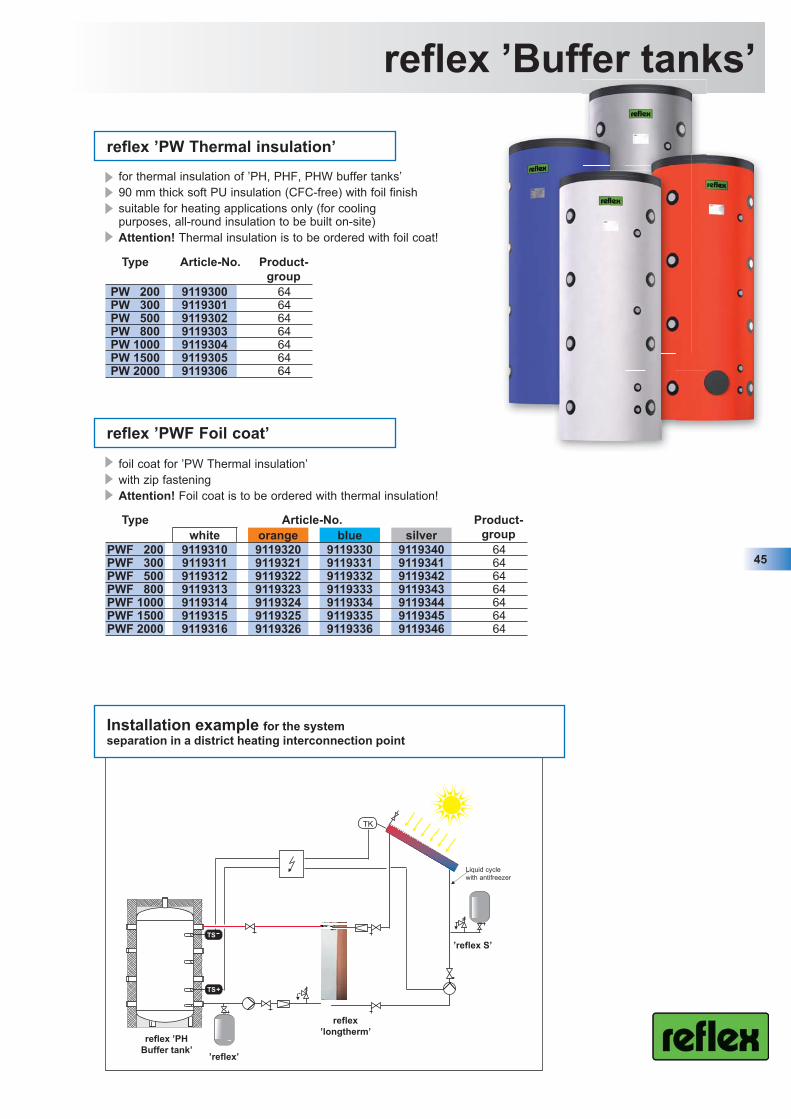
reflex ’PWF Foil coat’
foil coat for ’PW Thermal insulation’with zip fasteningAttention! Foil coat is to be ordered with thermal insulation!
Type Article-No. Product-group
PW 200 9119300 64PW 300 9119301 64PW 500 9119302 64PW 800 9119303 64PW 1000 9119304 64PW 1500 9119305 64PW 2000 9119306 64
reflex ’PW Thermal insulation’
45
reflex ’Buffer tanks’
Installation example for the system separation in a district heating interconnection point
’reflex S’
reflex ’PH Buffer tank’
reflex ’longtherm’
’reflex’
Liquid cycle with antifreezer
for thermal insulation of ’PH, PHF, PHW buffer tanks’90 mm thick soft PU insulation (CFC-free) with foil finishsuitable for heating applications only (for cooling purposes, all-round insulation to be built on-site)Attention! Thermal insulation is to be ordered with foil coat!
PI0418Fe_9571119_ProductGuide_2009_engl.indd 45 22.4.2009 09:38:45

reflex ’Buffer tanks’
46
Selection
Available heat capacity in kW/h for recharging respectively dischar-ging the buffer tank at temperature differences between flow and return temperature of 20, 30, 40 and 50 K.
The values in the tables are to be regarded as a guide. A precise calculation is performed in collaboration with the designer consultant or the boiler manufacturer.
Nominal volume Q20 Q30 Q40 Q50
Buffer tank kWh kWh kWh kWh300 6 9 13 16500 10 16 21 26800 17 25 33 42
1000 21 31 42 521500 31 47 63 782000 42 63 84 105
Living space Collector surface Buffer tankm² m² Litres
70 7 - 14 490 - 980100 10 - 20 700 - 1400150 15 - 30 1050 - 2100200 20 - 40 1400 - 2800250 25 - 50 1750 - 3500300 30 - 60 2100 - 4200350 35 - 70 2450 - 4900400 40 - 80 2800 - 5600450 45 - 90 3150 - 6300500 50 - 100 3500 - 7000
Buffer tanks in solar sytems with low to medium solar radiation
Charging
Discharging
Heatconsumer
Heatgenerator
reflex ’PH buffer tank’
PI0418Fe_9571119_ProductGuide_2009_engl.indd 46 22.4.2009 09:38:52

Hot water heaters
47
PI0418Fe_9571119_ProductGuide_2009_engl.indd 47 22.4.2009 09:38:52

Type Article-No. Weight Product-group
Ø D Hblue orange silver white kg mm mm
SB 100 7763000 7763100 7763900 7763800 38 60 512 849SF 120 --- --- --- 7759600 42 60 560 800SB 150 7750100 7750600 7764100 7763600 54 60 540 1222SB 200 7750200 7750700 7764200 7763300 65 60 540 1473SB 300 7750300 7750800 7764300 7763400 99 60 700 1334SB 400 7750400 7750900 7764400 7763500 119 60 700 1631SB 500 7750500 7751000 7764500 7763700 170 60 700 1961
SF 750* --- --- --- 7754600 227 60 9101 20001
SF 1000* --- --- --- 7754700 288 60 10102 20252
SF 1500* --- --- --- 7800700 401 51 12003 22163
SF 2000* --- --- --- 7800800 571 51 14004 21264
* - ’SF 750 and 1000’ are delivered with 2 built-in anodes - Soft foam white jacket will be - ’SF 1500 and 2000’ are delivered 2 power anodes delivered in separate package 1) without insulation Ø D = 750 mm, H = 1932 mm 3) without insulation Ø D = 1000 mm, H = 2019 mm2) without insulation Ø D = 850 mm, H = 1959 mm 4) without insulation Ø D = 1200 mm, H = 2019 mm
Type Article-No. Weight Product-group
H Dblue orange silver white kg mm mm
US 150 7762000 7762100 7765000 7761900 72 62 590 995US 250 7762500 7762600 7765100 7761300 99 62 644 1095
48
reflex ’Hot water heaters’
D
H
∅ D
H
∅ D
SF 120 Litres
H
SB 100, 150 - 1000 Litres
reflex ’SB, SF Hot water heaters’
floor standing indirect fired water heater heavy duty S235JRG2 (RSt 37-2) quality steelcorrosion resistant glass-lined tank according to German DIN 4753magnesium anode rod(s) for tank protectionhigh capacity, low pressure-drop glass-linedheat exchangerfactory mounted thermometerextra thick (50-80 mm) PU foam insulation’SB’ steel jacket in various colours,’SF’ foil jacket in various coloursclean-out and inspection accessmax. operating pressure: 10 bar (tank), 16 bar (coil)max. operating temperature: 95 °C (tank), 110 °C (coil)
reflex ’US Hot water heaters’
horizontal indirect fired water heaterheavy duty S235JRG2 (RSt 37-2) steel corrosion resistant glass-lined tank according to German DIN 4753magnesium anode rod for tank protectionhigh capacity, low pressure-drop glass lined heat exchangerfactory mounted thermometerextra thick PU foam insulationsteel jacket in various coloursrobust frame to carry 240 kgmax. operating pressure: 10 bar (tank), 16 bar (coil)max. operating temperature: 95 °C (tank), 110 °C (coil)
PI0418Fe_9571119_ProductGuide_2009_engl.indd 48 22.4.2009 09:38:54

Type Article-No. Weight Product-group
Ø D Hblue orange silver white grey kg mm mm
SF 200/2 --- --- --- 7743400 --- 72 61 540 1473SB 300/2 7740500 7760600 7741600 7742200 --- 106 61 600 1834SF 300/2 --- --- --- --- 7753300 106 61 700 1334SB 400/2 7761200 7767100 7742300 7742400 --- 130 61 700 1631SB 500/2 7757000 7740700 7741700 7707500 --- 160 61 700 1961
SF 750/2* --- --- --- 7743200 --- 217 61 9101 20001
SF 1000/2* --- --- --- 7743300 --- 275 61 10102 20252
* Soft foam white jacket will be delivered in separate package1) without insulation Ø D = 750 mm, H = 1932 mm2) without insulation Ø D = 850 mm, H = 1959 mm
49
reflex ’Hot water heaters’∅ D
H
reflex ’SB/2, SF/2 Solar hot water heaters’
floor standing indirect fired/solar water heaterheavy duty S235JRG2 (RSt 37-2) quality steel corrosion resistant glass-lined tank according to German DIN 4753magnesium anode rod(s) for tank protectionhigh capacity, low pressure-drop glass-lined heat exchangersfactory mounted thermometerextra thick (50-80 mm) PU foam insulationopening for an additional electrical heating element’SB’ steel jacket in various colours,’SF’ foil jacket in various coloursclean-out and inspection accessmax. operating pressure: 10 bar (tank), 16 bar (coil)max. operating temperature: 95 °C (tank), 110 °C (coil)
PI0418Fe_9571119_ProductGuide_2009_engl.indd 49 22.4.2009 09:38:57
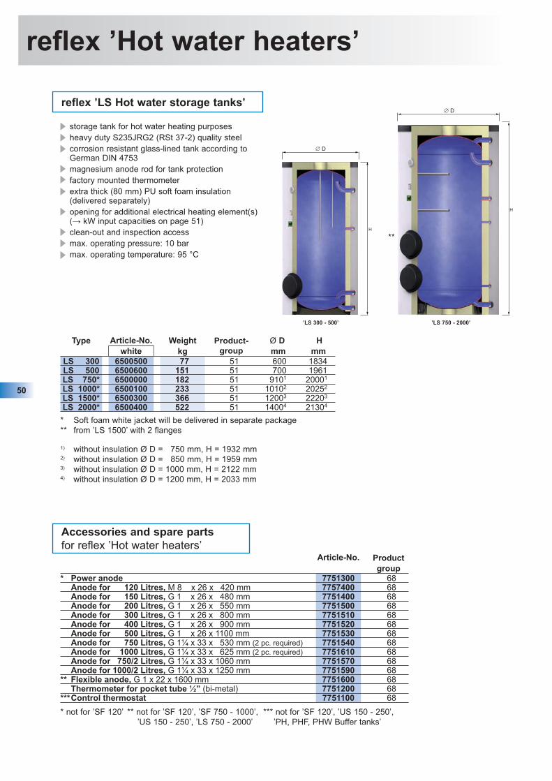
Type Article-No. Weight Product-group
Ø D Hwhite kg mm mm
LS 300 6500500 77 51 600 1834LS 500 6500600 151 51 700 1961LS 750* 6500000 182 51 9101 20001
LS 1000* 6500100 233 51 10102 20252
LS 1500* 6500300 366 51 12003 22203
LS 2000* 6500400 522 51 14004 21304
* Soft foam white jacket will be delivered in separate package** from ’LS 1500’ with 2 flanges
1) without insulation Ø D = 750 mm, H = 1932 mm2) without insulation Ø D = 850 mm, H = 1959 mm3) without insulation Ø D = 1000 mm, H = 2122 mm4) without insulation Ø D = 1200 mm, H = 2033 mm
50
reflex ’Hot water heaters’
∅ D
H
’LS 300 - 500’
∅ D
H
**
’LS 750 - 2000’
reflex ’LS Hot water storage tanks’
storage tank for hot water heating purposesheavy duty S235JRG2 (RSt 37-2) quality steelcorrosion resistant glass-lined tank according to German DIN 4753magnesium anode rod for tank protectionfactory mounted thermometerextra thick (80 mm) PU soft foam insulation(delivered separately) opening for additional electrical heating element(s)(→ kW input capacities on page 51)clean-out and inspection access max. operating pressure: 10 barmax. operating temperature: 95 °C
Accessories and spare partsfor reflex ’Hot water heaters’
Article-No. Productgroup
* Power anode 7751300 68Anode for 120 Litres, M 8 x 26 x 420 mm 7757400 68Anode for 150 Litres, G 1 x 26 x 480 mm 7751400 68Anode for 200 Litres, G 1 x 26 x 550 mm 7751500 68Anode for 300 Litres, G 1 x 26 x 800 mm 7751510 68Anode for 400 Litres, G 1 x 26 x 900 mm 7751520 68Anode for 500 Litres, G 1 x 26 x 1100 mm 7751530 68Anode for 750 Litres, G 1¼ x 33 x 530 mm (2 pc. required) 7751540 68Anode for 1000 Litres, G 1¼ x 33 x 625 mm (2 pc. required) 7751610 68Anode for 750/2 Litres, G 1¼ x 33 x 1060 mm 7751570 68Anode for 1000/2 Litres, G 1¼ x 33 x 1250 mm 7751590 68
** Flexible anode, G 1 x 22 x 1600 mm 7751600 68Thermometer for pocket tube ½” (bi-metal) 7751200 68
***Control thermostat 7751100 68
* not for ’SF 120’ ** not for ’SF 120’, ’SF 750 - 1000’, *** not for ’SF 120’, ’US 150 - 250’, ’US 150 - 250’, ’LS 750 - 2000’ ’PH, PHF, PHW Buffer tanks’
PI0418Fe_9571119_ProductGuide_2009_engl.indd 50 22.4.2009 09:38:58

51
Accessories reflex ’Hot water heaters’
Flange cap for ’EEHR’
for reflex ’Hot water heaters’, ’Hot water storage tanks’ and ’PHF Buffer tanks’ Rp 1½ socket for screw-in element ’EEHR’replaces the factory-mounted blank flange of the inspection accessgasket ring to be ordered separately
Storage Article-No. Productsize group
* 150 - 500 7760000 68750 - 2000 7760100 68
Seal* 150 - 500 7760900 68
750 - 2000 7761030 68* for ’PHF Buffer tanks’ < 2000 litres (→ p. 44)
* not for ’SB/SF 300/2’, Ø 600
Type Article-No. Product Storage Power Voltage Fitting W H Dgroup size/l kW V length/mm mm mm mm
EFHR 4,0 9116314 68 150 - 500 4.0 / 2.7 / 2.0 400 295 150 110 185EFHR 6,0 9116315 68 300 - 500 6.0 / 4.0 / 3.0 400 395 150 110 185
* EFHR 8,0 9116316 68 300 - 500 8.0 / 5.5 / 4.0 400 495 150 110 185*EFHR 10,0 9116317 68 300 - 500 10.0 / 6.7 / 5.0 400 495 150 110 185EFHR 16,0 9116501 68 750 - 1000 16.0 / 11.0 / 8.0 400 610 225 140 280EFHR 19,0 9116502 68 1000 -2000 19.0 / 12.7 / 9.0 400 740 225 140 280EFHR 25,0 9115569 68 1000 -2000 25.0 / 18.8 /12.5 400 740 225 140 280
reflex ’EFHR Electricflange heater’
suitable for continous operation as electrical heating3 power levels, reconnectablesafety temperature cut-off max. 120 °Ccontrol thermostat up to 80 °Con-site electrical connectionincluding flange and sealing
Fitting length HD
W
Fitting length 125
G 1½, flat sealing
90
* not for ’SB/SF 300/2’, Ø 600
Type Article-No. Product Storage Power Voltage Fittinggroup size/l kW V length/mm
EEHR 1,8 9200277 68 from 150 1.8 230 375EEHR 3,0 7755100 68 from 150 3.0 230 375EEHR 4,5 7755300 68 from 300 4.5 400 450
* EEHR 6,0 7755400 68 from 300 6.0 400 510
reflex ’EEHR Electricscrew-in heater’
for (additional) heating purposes for reflex ’Hot water heaters’, ’Solar hot water heaters’, ’Hot water storage tanks’ and ’PHF Buffer tanks’ to be used as back-up for space/solar heating; max. water hardness 14 °dHcontrol thermostat up to 80 °C and pilot lamp
PI0418Fe_9571119_ProductGuide_2009_engl.indd 51 22.4.2009 09:39:01

Your Reflex export help team
52
Export +49 23 82 / 70 69 -... Extension Fax
Managing director Harald Schwenzig - 522 - 558 [email protected] manager Willem Tieleman - 519 - 558 willem.tieleman@refl ex.deExport assistant Verena Steuer - 524 - 558 [email protected]
Export assistant - Area 1 Stefan Echtermann - 528 - 558 stefan.echtermann@refl ex.deExport assistant - Area 1 Monika Schneider - 535 - 558 monika.schneider@refl ex.deExport assistant - Area 2 Florence Margout - 509 - 558 fl orence.margout@refl ex.deExport assistant - Area 2 Friederike Schulze-Henne - 562 - 558 [email protected] assistant - Area 3 Alena Diner - 561 - 558 alena.diner@refl ex.deExport assistant - Area 3 Ludmila Aydin - 563 - 558 ludmila.aydin@refl ex.de
Export ManagerArea 1Country Rein van Rijt - 559 - 558 rein.vanrijt@refl ex.de
Australia / New ZealandBaltic statesFar EastCanadaSwitzerlandTurkeyUSA
Area 2Country Dipl.-Ing. Moustapha Fahmy - 560 - 558 moustapha.fahmy@refl ex.de
Belgium / Luxembourg Portugal / SpainFrance South AmericaIndia / Pakistan CypreItalyMiddle East / IranNorth Africa / Central Africa
Area 3Country Jörg Bodenbender - 533 - 558 joerg.bodenbender@refl ex.de
Bosnia-Herzegovina SloveniaBulgaria ScandinaviaJugoslavia UkraineCIS-States HungaryCroatiaRomania
Productmarketing
Pressurization units Matthias Feld - 536 - 502 [email protected], degassing Andreas Rüsing - 567 - 502 andreas.ruesing@refl ex.deHeat exchangers, water heaters Detlev Bartkowiak - 538 - 501 detlev.bartkowiak@refl ex.deTraining, communication Dipl.-Ing. (FH) Raimund Hielscher - 582 - 39 582 raimund.hielscher@refl ex.deCommunication, PR design Sara Linckamp - 566 - 39 566 sara.linckamp@refl ex.dePressure vessels, Techn. hotline Helmut Kittel - 546 - 501 helmut.kittel@refl ex.de
Quality management
Management Rolf Matz - 530 - 39 530 [email protected]
PI0418Fe_9571119_ProductGuide_2009_engl.indd 52 22.4.2009 09:39:02

Reflex International
53
Reflex POLSKA Sp. z o.o.Dr. Alfred Jerszynskiul. Unii Lubelskiej 3PL-61-249 PoznánTel.: +48 61 653 14 02Fax: +48 61 653 14 [email protected]
Reflex CZ, s.r.o.Vit GabrielPrumyslová 5CZ-108 00 Prague 10Tel.: +420 2 720 903 01Fax: +420 2 720 903 [email protected]
Reflex SK, s.r.o.Dipl.-Ing. Peter PáltikRakovoSK-038 42 PribovceTel.: +421 43 423 0983Fax: +421 43 423 [email protected]
Reflex Nederland B.V.Roderick van GeelKerkstraat 2aNL-2971 AL Bleskensgraaf CATel.: +31 184 67 05 30Fax: +31 184 67 05 [email protected]
Reflex Austria GmbHMartin TrippMerianstraße 38A-5020 SalzburgTel.: +43 6 62 87 53 26Fax: +43 6 62 87 53 26 [email protected]
Refl ex (Shanghai) Heating & Energy Equipment Ltd., Co.Raymund ChenUnit D, 7F, No. 788, Ding Xi Road200052 Shanghai, P.R.ChineTel.: +86 21 611 695 01Fax: +86 21 611 695 00www.reflexcn.cn
Reflex Hellas A.E.Tina LamprinidouVouliagmenis Av. 165GR - 17237 DafniTel.: +30 210 67 14 737Fax: +30 210 67 14 [email protected]
Office Reflex HungaryDomotech BtPeter GösiFalk Miksa ú 4H-1055 BudapestTel./Fax: +36 133 180 82Mobile: +36 309 311 850 [email protected]
Office Reflex Belux Flandern/LuxembourgJacques Jageneau GSM: +32 475 41 25 80Fax: +32 11 37 84 [email protected]
Wallonia -Service dienstJean-Claude GodichalGSM: +32 475 47 14 97Fax: +32 71 49 02 [email protected]
Office Reflex RussiaMaxim MelnikKastoma Rowskij Per 3RUS-107120 MoscouTel.: +7 495 363 15 49Fax: +7 495 363 15 [email protected]
Office Reflex FranceSales managerPascal SpillTel.: +33 6 08 76 62 02pascal.spill@refl exfrance.fr
Stock/SolarThierry HetzelTel.: +33 3 88 63 28 20Fax: +33 3 88 63 71 16thierry.hetzel@refl exfrance.frwww.reflexfrance.fr
Office Reflex Baltic statesVygantas MilaknisPanevézio 12-6P.O. Box 35LT-42158 RokiskisTel.: +370 458 32 792Fax: +370 458 31 [email protected]
Office Reflex UKDan TestarStablegate, 84 Silvester RoadUK - P08 8TS Waterlooville, HampshireTel.: +44 75 90 07 92 60dan.testar@refl exuk.co.ukwww.reflexuk.co.uk
Subsidiaries
Representation offices
PI0418Fe_9571119_ProductGuide_2009_engl.indd 53 22.4.2009 09:39:04

Reflex - Microbubble and Dirt Separators
Very practical for everyday use: Reflex presents its CD-ROM with compre-hensive programs of calculation, CAD drawings and lots of information for consultants, installers and trainees. A real source of information is the new Reflex technical manual which deals in detail with the separation of air and dirt. Both are free available on request or can be downloaded from our site www.reflex.de.
Make an additional advantage by assi-sting to our regular training sessions run by qualified Reflex staff but also with participants from colleges and professionals in the industry.
The complete range of automatic airvents,
microbubble and dirt separators.
arators
of s,
nd s.
NEW!
PI0418Fe_9571119_ProductGuide_2009_engl.indd 54 22.4.2009 09:39:04

55
Notes
PI0418Fe_9571119_ProductGuide_2009_engl.indd 55 22.4.2009 09:39:10

New Reflex technologies are to provide advantages not only to human beings, but also to the environment. This is the principle on which we base all our development, planning, and manufac-turing.
We comply with our responsibility as manufacturer by the purposeful selectionof materials and production technolo-gies - the environmental - impacts are as low as possible.
PI0
418F
e / 9
5711
19 /
02 -
09 /
2.00
0S
ubje
ct to
tech
nica
l mod
ifica
tions
- P
rinte
d in
Ger
man
y
Reflex Winkelmann GmbH + Co. KG
Gersteinstrasse 1959227 AhlenGermany
Phone: +49 (0) 23 82 / 70 69 - 0Fax: +49 (0) 23 82 / 70 69 - 558www.reflex.de
Reflex – Responsibility in the interests of the environment
PI0418Fe_9571119_ProductGuide_2009_engl.indd 56 22.4.2009 09:39:10


