NOTICE The manufacturer will accept no responsability for any electrical damage resulting from improper installation of this product, be that either damage to the vehicle itself or to the installed device. This device must be installed by a certiied technician. Please review the Installation Guide carefully before beginning any work.
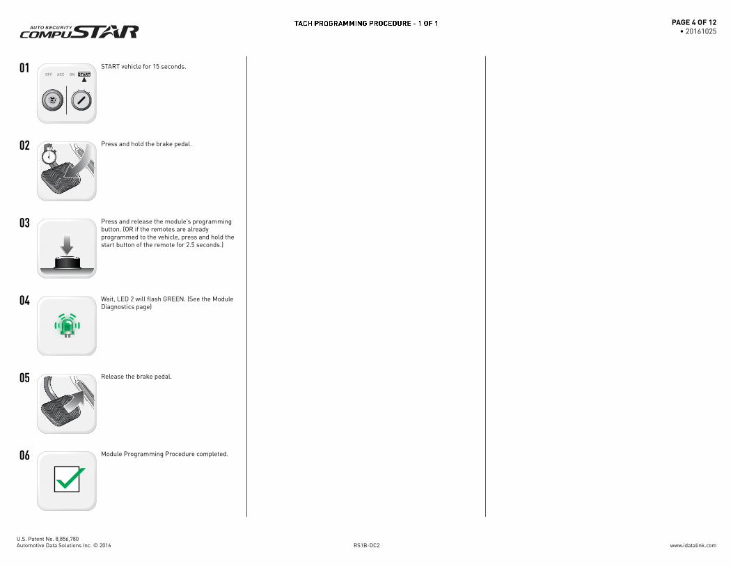
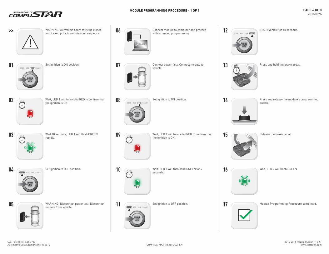
Press and release the module’s programming button. (OR if the remotes are already programmed to the vehicle, press and hold the start button of the remote for 2.5 seconds.)
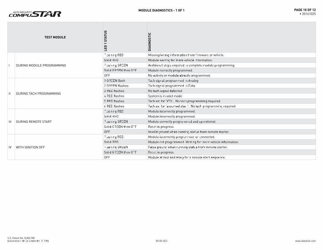
Wait, LED 2 will fl ash GREEN. (See the Module Diagnostics page)
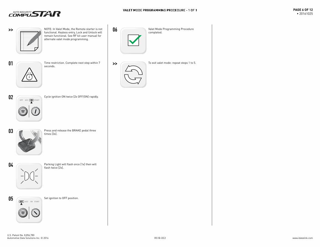
NOTE: In Valet Mode, the Remote starter is not functional. Keyless entry, Lock and Unlock will remain functional. See RF kit user manual for alternate valet mode programming.
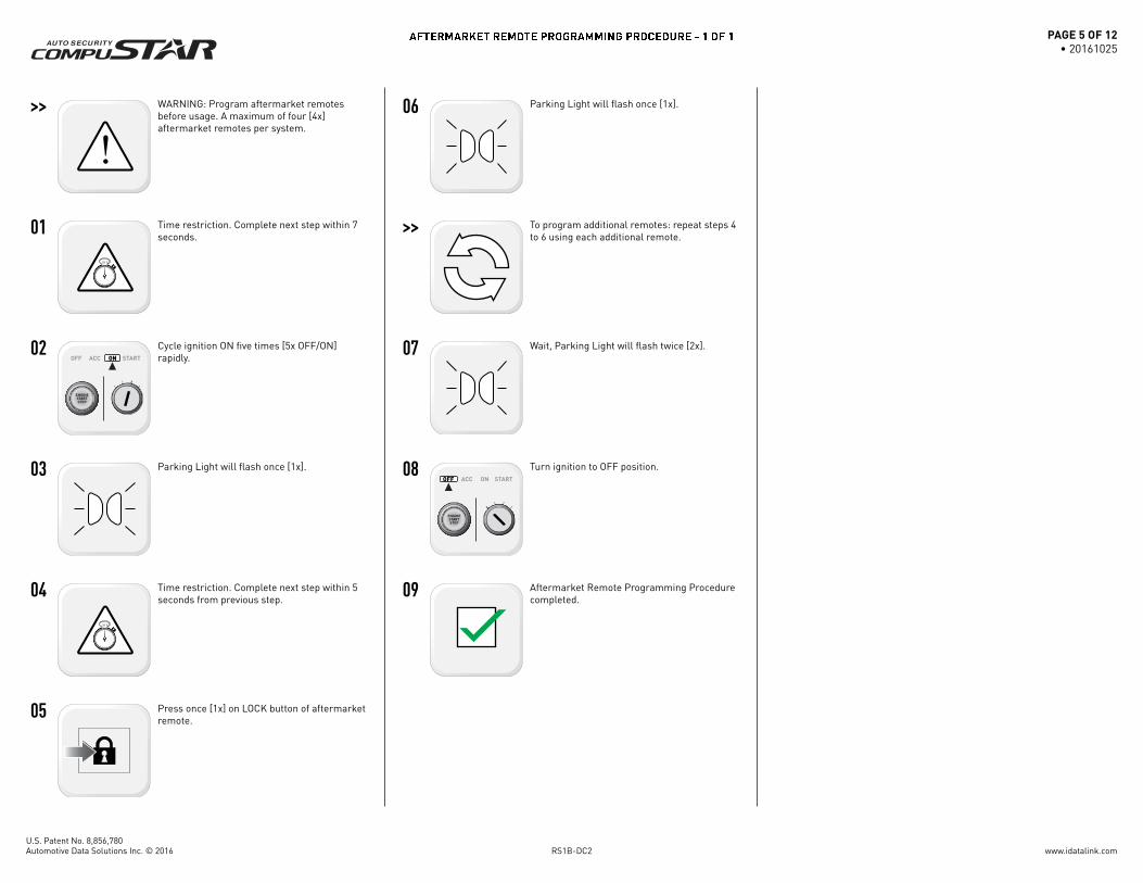
Time restriction. Complete next step within 7 seconds.
Cycle ignition ON twice [2x OFF/ON] rapidly.
Press and release the BRAKE pedal three times [3x].
Parking Light will fl ash once [1x] then will fl ash twice [2x].
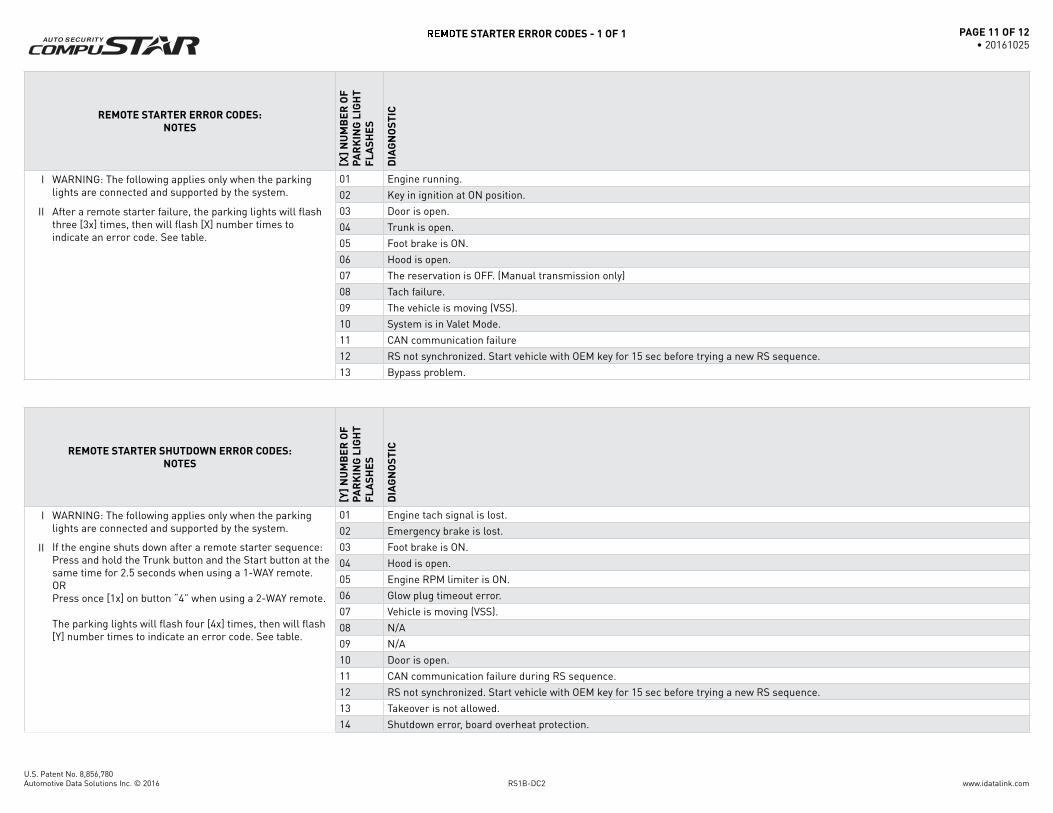
I WARNING: The following applies only when the parking lights are connected and supported by the system.
01 Engine running.
02 Key in ignition at ON position.
II After a remote starter failure, the parking lights will fl ash three [3x] times, then will fl ash [X] number times to indicate an error code. See table.
03 Door is open.
04 Trunk is open.
05 Foot brake is ON.
06 Hood is open.
07 The reservation is OFF. (Manual transmission only)
08 Tach failure.
09 The vehicle is moving (VSS).
10 System is in Valet Mode.
11 CAN communication failure
12 RS not synchronized. Start vehicle with OEM key for 15 sec before trying a new RS sequence.
13 Bypass problem.
REMOTE STARTER SHUTDOWN ERROR CODES:
NOTES
[Y]
NU
MB
ER
OF
PA
RK
ING
LIG
HT
FL
AS
HE
S
DIA
GN
OS
TIC
I WARNING: The following applies only when the parking lights are connected and supported by the system.
01 Engine tach signal is lost.
02 Emergency brake is lost.
II If the engine shuts down after a remote starter sequence: Press and hold the Trunk button and the Start button at the same time for 2.5 seconds when using a 1-WAY remote. OR Press once [1x] on button “4” when using a 2-WAY remote.
The parking lights will fl ash four [4x] times, then will fl ash [Y] number times to indicate an error code. See table.
03 Foot brake is ON.
04 Hood is open.
05 Engine RPM limiter is ON.
06 Glow plug timeout error.
07 Vehicle is moving (VSS).
08 N/A
09 N/A
10 Door is open.
11 CAN communication failure during RS sequence.
12 RS not synchronized. Start vehicle with OEM key for 15 sec before trying a new RS sequence.
The manufacturer will accept no responsability for any electrical damage resulting from improper installation of this product, be that either damage to the vehicle itself or to the installed device. This device must be installed by a certiied technician. Please review the Installation Guide carefully before beginning any work.
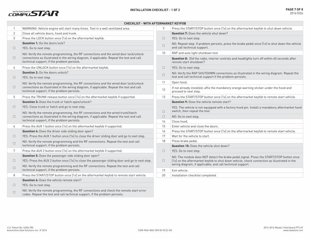
1 WARNING: Vehicle engine will start many times. Test in a well ventilated area.
2 Close all vehicle doors, hood and trunk.
3 Press the LOCK button once [1x] on the aftermarket keyfob.
Question 1: Do the doors lock?
YES: Go to next step.
NO: Verify the remote programming, the RF connections and the wired door lock/unlock connections as illustrated in the wiring diagram, if applicable. Repeat the test and call technical support, if the problem persists.
4 Press the UNLOCK button once [1x] on the aftermarket keyfob.
Question 2: Do the doors unlock?
YES: Go to next step.
NO: Verify the remote programming, the RF connections and the wired door lock/unlock connections as illustrated in the wiring diagram, if applicable. Repeat the test and call technical support, if the problem persists.
5 Press the TRUNK release button once [1x] on the aftermarket keyfob if supported.
Question 3: Does the trunk or hatch open/unlock?
YES: Close trunk or hatch and go to next step.
NO: Verify the remote programming, the RF connections and the wired trunk/hatch connections as illustrated in the wiring diagram, if applicable. Repeat the test and call technical support, if the problem persists.
6 Press the AUX 1 button once [1x] on the aftermarket keyfob if supported.
Question 4: Does the driver side sliding door open?
YES: Press the AUX 1 button once [1x] to close the driver sliding door and go to next step.
NO: Verify the remote programming and the RF connections. Repeat the test and call technical support, if the problem persists.
7 Press the AUX 2 button once [1x] on the aftermarket keyfob if supported.
Question 5: Does the passenger side sliding door open?
YES: Press the AUX 2 button once [1x] to close the passenger sliding door and go to next step.
NO: Verify the remote programming and the RF connections. Repeat the test and call technical support, if the problem persists.
8 Press the START/STOP button once [1x] on the aftermarket keyfob to remote start vehicle.
Question 6: Does the vehicle remote start?
YES: Go to next step.
NO: Verify the remote programming, the RF connections and check the remote start error codes. Repeat the test and call technical support, if the problem persists.
9 Press the START/STOP button once [1x] on the aftermarket keyfob to shut down vehicle.
Question 7: Does the vehicle shut down?
YES: Go to next step.
NO: Repeat step. If problem persists, press the brake pedal once [1x] to shut down the vehicle and call technical support.
10 RAP and auto light shutdown test
Question 8: Did the radio, interior controls and headlights turn off within 60 seconds after remote start shutdown?
YES: Go to next step.
NO: Verify the RAP SHUTDOWN connections as illustrated in the wiring diagram. Repeat the test and call technical support if the problem persists.
11 Open hood.
12If not already installed, afix the mandatory orange warning sticker under the hood and proceed to next step.
13 Press the START/STOP button once [1x] on the aftermarket keyfob to remote start vehicle.
Question 9: Does the vehicle remote start?
YES: The vehicle is not equipped with a factory hood pin. Install a mandatory aftermarket hood switch, then repeat the test.
NO: Go to next step.
14 Close hood.
15 Enter vehicle and close the doors.
16 Press the START/STOP button once [1x] on the aftermarket keyfob to remote start vehicle.
17 Wait for the vehicle to start.
18 Press brake pedal.
Question 10: Does the vehicle shut down?
YES: Go to next step.
NO: The module does NOT detect the brake pedal signal. Press the START/STOP button once [1x] on the aftermarket keyfob to shut down vehicle, check connection as illustrated in the wiring diagram, if applicable, and call technical support.
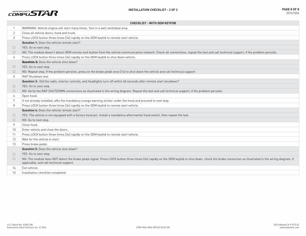
1 WARNING: Vehicle engine will start many times. Test in a well ventilated area.
2 Close all vehicle doors, hood and trunk.
3 Press LOCK button three times [3x] rapidly on the OEM keyfob to remote start vehicle.
Question 1: Does the vehicle remote start?
YES: Go to next step.
NO: The module doesn't detect OEM remote lock button from the vehicle communication network. Check all connections, repeat the test and call technical support, if the problem persists.
4 Press LOCK button three times [3x] rapidly on the OEM keyfob to shut down vehicle.
Question 2: Does the vehicle shut down?
YES: Go to next step.
NO: Repeat step. If the problem persists, press on the brake pedal once [1x] to shut down the vehicle and call technical support.
5 RAP Shutdown test
Question 3: Did the radio, interior controls, and headlights turn off within 60 seconds after remote start shutdown?
YES: Go to next step.
NO: Verify the RAP SHUTDOWN connections as illustrated in the wiring diagram. Repeat the test and call technical support, if the problem persists.
6 Open hood.
7 If not already installed, afix the mandatory orange warning sticker under the hood and proceed to next step.
8 Press LOCK button three times [3x] rapidly on the OEM keyfob to remote start vehicle.
Question 4: Does the vehicle remote start?
YES: The vehicle is not equipped with a factory hood pin. Install a mandatory aftermarket hood switch, then repeat the test.
NO: Go to next step.
9 Close hood.
10 Enter vehicle and close the doors.
11 Press LOCK button three times [3x] rapidly on the OEM keyfob to remote start vehicle.
12 Wait for the vehicle to start.
13 Press brake pedal.
Question 5: Does the vehicle shut down?
YES: Go to next step.
NO: The module does NOT detect the brake pedal signal. Press LOCK button three times [3x] rapidly on the OEM keyfob to shut down, check the brake connection as illustrated in the wiring diagram, if applicable, and call technical support.
The manufacturer will accept no responsability for any electrical damage resulting from improper installation of this product, be that either damage to the vehicle itself or to the installed device. This device must be installed by a certiied technician. Please review the Installation Guide carefully before beginning any work.
1 WARNING: Vehicle engine will start many times. Test in a well ventilated area.
2 Close all vehicle doors, hood and trunk.
3 Press the LOCK button once [1x] on the aftermarket keyfob.
Question 1: Do the doors lock?
YES: Go to next step.
NO: Verify the remote programming, the RF connections and the wired door lock/unlock connections as illustrated in the wiring diagram, if applicable. Repeat the test and call technical support, if the problem persists.
4 Press the UNLOCK button once [1x] on the aftermarket keyfob.
Question 2: Do the doors unlock?
YES: Go to next step.
NO: Verify the remote programming, the RF connections and the wired door lock/unlock connections as illustrated in the wiring diagram, if applicable. Repeat the test and call technical support, if the problem persists.
5 Press the TRUNK release button once [1x] on the aftermarket keyfob if supported.
Question 3: Does the trunk or hatch open/unlock?
YES: Close trunk or hatch and go to next step.
NO: Verify the remote programming, the RF connections and the wired trunk/hatch connections as illustrated in the wiring diagram, if applicable. Repeat the test and call technical support, if the problem persists.
6 Press the AUX 1 button once [1x] on the aftermarket keyfob if supported.
Question 4: Does the driver side sliding door open?
YES: Press the AUX 1 button once [1x] to close the driver sliding door and go to next step.
NO: Verify the remote programming and the RF connections. Repeat the test and call technical support, if the problem persists.
7 Press the AUX 2 button once [1x] on the aftermarket keyfob if supported.
Question 5: Does the passenger side sliding door open?
YES: Press the AUX 2 button once [1x] to close the passenger sliding door and go to next step.
NO: Verify the remote programming and the RF connections. Repeat the test and call technical support, if the problem persists.
8 Press the START/STOP button once [1x] on the aftermarket keyfob to remote start vehicle.
Question 6: Does the vehicle remote start?
YES: Go to next step.
NO: Verify the remote programming, the RF connections and check the remote start error codes. Repeat the test and call technical support, if the problem persists.
9 Press the START/STOP button once [1x] on the aftermarket keyfob to shut down vehicle.
Question 7: Does the vehicle shut down?
YES: Go to next step.
NO: Repeat step. If problem persists, press the brake pedal once [1x] to shut down the vehicle and call technical support.
10 RAP and auto light shutdown test
Question 8: Did the radio, interior controls and headlights turn off within 60 seconds after remote start shutdown?
YES: Go to next step.
NO: Verify the RAP SHUTDOWN connections as illustrated in the wiring diagram. Repeat the test and call technical support if the problem persists.
11 Open hood.
12If not already installed, afix the mandatory orange warning sticker under the hood and proceed to next step.
13 Press the START/STOP button once [1x] on the aftermarket keyfob to remote start vehicle.
Question 9: Does the vehicle remote start?
YES: The vehicle is not equipped with a factory hood pin. Install a mandatory aftermarket hood switch, then repeat the test.
NO: Go to next step.
14 Close hood.
15 Enter vehicle and close the doors.
16 Press the START/STOP button once [1x] on the aftermarket keyfob to remote start vehicle.
17 Wait for the vehicle to start.
18 Press brake pedal.
Question 10: Does the vehicle shut down?
YES: Go to next step.
NO: The module does NOT detect the brake pedal signal. Press the START/STOP button once [1x] on the aftermarket keyfob to shut down vehicle, check connection as illustrated in the wiring diagram, if applicable, and call technical support.
1 WARNING: Vehicle engine will start many times. Test in a well ventilated area.
2 Close all vehicle doors, hood and trunk.
3 Press LOCK button three times [3x] rapidly on the OEM keyfob to remote start vehicle.
Question 1: Does the vehicle remote start?
YES: Go to next step.
NO: The module doesn't detect OEM remote lock button from the vehicle communication network. Check all connections, repeat the test and call technical support, if the problem persists.
4 Press LOCK button three times [3x] rapidly on the OEM keyfob to shut down vehicle.
Question 2: Does the vehicle shut down?
YES: Go to next step.
NO: Repeat step. If the problem persists, press on the brake pedal once [1x] to shut down the vehicle and call technical support.
5 RAP Shutdown test
Question 3: Did the radio, interior controls, and headlights turn off within 60 seconds after remote start shutdown?
YES: Go to next step.
NO: Verify the RAP SHUTDOWN connections as illustrated in the wiring diagram. Repeat the test and call technical support, if the problem persists.
6 Open hood.
7 If not already installed, afix the mandatory orange warning sticker under the hood and proceed to next step.
8 Press LOCK button three times [3x] rapidly on the OEM keyfob to remote start vehicle.
Question 4: Does the vehicle remote start?
YES: The vehicle is not equipped with a factory hood pin. Install a mandatory aftermarket hood switch, then repeat the test.
NO: Go to next step.
9 Close hood.
10 Enter vehicle and close the doors.
11 Press LOCK button three times [3x] rapidly on the OEM keyfob to remote start vehicle.
12 Wait for the vehicle to start.
13 Press brake pedal.
Question 5: Does the vehicle shut down?
YES: Go to next step.
NO: The module does NOT detect the brake pedal signal. Press LOCK button three times [3x] rapidly on the OEM keyfob to shut down, check the brake connection as illustrated in the wiring diagram, if applicable, and call technical support.