12
November 2016 Product Information RCN 2000 RCN 5000 RCN 8000 Absolute Angle Encoders for Safety-Related Applications

November 2016
Product Information
RCN 2000RCN 5000RCN 8000Absolute Angle Encoders for Safety-Related Applications

Product Information RCN 2000/5000/8000 11/20162
RCN 2000 seriesAbsolute angle encoders for safety-related applications• Safe absolute position• Hollow through shaft ¬ 20 mm• System accuracy ±2.5” and ±5”
A =Bearing ofmating shaftd =Compressed air inletk = Required mating dimensions1 = Mark for 0° position ±5°2 = Cable support3 = Free space for customer4 = Screw penetration 4.5±0.5 mm5 = Accessory: Ring nut ID 336669-036 = Accessory: Catch ID 817921-017 = Screw penetration > 7.5 mm8 = 2x spring pins ISO 8752 – 2.5x10 – St9 = When using spring pins, provide additional back-off threads (M3)10 = Direction of shaft rotation for output signals as per the interface description
kAlternative mounting option with front-end shaft coupling
kShaft coupling with ring nut and catch Shown without ring nut and catch

Product Information RCN 2000/5000/8000 11/2016 3
AbsoluteRCN 2510 RCN 2310
Measuring standard DIADUR circular scale with absolute and incremental track (16 384 lines)
System accuracy ±2.5” ±5”
Position error per signal period ±0.3” ±0.4”
Functional safetyFor applications up to
• SIL 2 according to EN 61508 (further basis for testing: EN 61800-5-2)• Category 3, PL d according to EN ISO 13 849-1:2008
PFH 25 · 10–9
Safe position1) Encoder: ±0.22° (safety-related measuring step: SM = 0.088°)Mechanical connection: Fault exclusions for loosening of the housing/flange and hollow shaft (pages 10/11)
Interface EnDat 2.2
Ordering designation EnDat22
Positions per revolution 268 435 456 (28 bits) 67 108 864 (26 bits)
Electrically permissible speed 3 000 rpm for continuous position value
Clock frequencyCalculation time tcal
16 MHz 5 µs
Electrical connection Separate adapter cable connectable to encoder via quick disconnect
Cable length 100 m (with HEIDENHAIN cable; clock frequency 8 MHz)
Voltage supply DC 3.6 V to 14 V
Power consumption2) (maximum) 3.6 V: 1.1 W14 V: 1.3 W
Current consumption (typical) 5 V: 140 mA (without load)
Shaft Hollow through shaft D = 20 mm
Mechanically permissible speed 1 500 rpmTemporary: 3 000 rpm3) (speeds over 1 500 rpm require consultation)
Torque (friction) 3.3 Nm (typical starting torque: ≤ 0.08 Nm at 20 °C)
Moment of inertia Rotor (hollow shaft): 180 · 10–6 kgm2
Stator (housing/flange): 670 · 10–6 kgm2
Permissible axial motion of measured shaft ±0.3 mm
Natural frequency 1000 Hz
Vibration 55 to 2 000 HzShock 6 ms
200 m/s2 (EN 60068-2-6) 200 m/s2 (EN 60068-2-27)
Operating temperature 0 °C to 50 °C 0 °C to 60 °C–20 °C to 60 °C 3)
Protection EN 60 529 IP64
Weight � 1.0 kg
1) Further tolerances may occur in subsequent electronics after position value comparison (contact manufacturer of subsequent electronics)2) See General electrical information in the Interfaces for HEIDENHAIN Encoders brochure3) No fault exclusion for loosening of the mechanical connection

Product Information RCN 2000/5000/8000 11/20164
kAlternative mounting option with front-end shaft coupling
kShaft coupling with ring nut and catch Shown without ring nut and catch
RCN 5000 seriesAbsolute angle encoders for safety-related applications• Safe absolute position• Hollow through shaft ¬ 35 mm• System accuracy ±2.5” and ±5”
A =Bearing ofmating shaftd =Compressed air inletk = Required mating dimensions1 = Mark for 0° position ±5°2 = Cable support3 = Free space for customer4 = Screw penetration 4.5±0.5 mm5 = Accessory: Ring nut ID 336669-176 = Accessory: Catch ID 817921-027 = Screw penetration > 7 mm8 = 2x spring pins ISO 8752 – 2.5x10 – St9 = When using spring pins, provide additional back-off threads (M3)10 = Direction of shaft rotation for output signals as per the interface description

Product Information RCN 2000/5000/8000 11/2016 5
AbsoluteRCN 5510 RCN 5310
Measuring standard DIADUR circular scale with absolute and incremental track (16 384 lines)
System accuracy ±2.5” ±5”
Position error per signal period ±0.3” ±0.4”
Functional safetyFor applications up to
• SIL 2 according to EN 61508 (further basis for testing: EN 61800-5-2)• Category 3, PL d according to EN ISO 13 849-1:2008
PFH 25 · 10–9
Safe position1) Encoder: ±0.22° (safety-related measuring step: SM = 0.088°)Mechanical connection: Fault exclusions for loosening of the housing/flange and hollow shaft (pages 10/11)
Interface EnDat 2.2
Ordering designation EnDat22
Positions per revolution 268 435 456 (28 bits) 67 108 864 (26 bits)
Electrically permissible speed 3 000 rpm for continuous position value
Clock frequencyCalculation time tcal
16 MHz 5 µs
Electrical connection Separate adapter cable connectable to encoder via quick disconnect
Cable length 100 m (with HEIDENHAIN cable; clock frequency 8 MHz)
Voltage supply DC 3.6 V to 14 V
Power consumption2) (maximum) 3.6 V: 1.1 W14 V: 1.3 W
Current consumption (typical) 5 V: 140 mA (without load)
Shaft Hollow through shaft D = 35 mm
Mechanically permissible speed 1500 rpmTemporary: 3 000 rpm3) (speeds over 1 500 rpm require consultation)
Torque (friction) 3.38 Nm (typical starting torque: ≤ 0.2 Nm at 20 °C)
Moment of inertia Rotor (hollow shaft): 130 · 10–6 kgm2
Stator (housing/flange): 1 010 · 10–6 kgm2
Permissible axial motion of measured shaft ±0.3 mm
Natural frequency 1000 Hz
Vibration 55 to 2 000 HzShock 6 ms
200 m/s2 (EN 60068-2-6) 200 m/s2 (EN 60068-2-27)
Operating temperature 0 °C to 50 °C 0 °C to 60 °C–20 °C to 60 °C 3)
Protection EN 60 529 IP64
Weight � 0.9 kg
1) Further tolerances may occur in subsequent electronics after position value comparison (contact manufacturer of subsequent electronics).2) See General electrical information in the Interfaces for HEIDENHAIN Encoders brochure3) No fault exclusion for loosening of the mechanical connection

Product Information RCN 2000/5000/8000 11/20166
RCN 8000 seriesAbsolute angle encoders for safety-related applications• Safe absolute position• Hollow through shaft ¬ 60 mm• System accuracy ±1” and ±2”
Shown without ring nut and catch
kShaft coupling with ring nut and catch
kAlternative mounting option with front-end shaft coupling
A =Bearing ofmating shaftd = Compressed air inletk = Required mating dimensions1 = Mark for 0° position ±5°2 = Cable support3 = Free space for customer4 = Shown rotated by 45°5 = Screw penetration 5.5±0.5 mm6 = Accessory: Ring nut ID 336669-117 = Accessory: Catch ID 817921-038 = Screw penetration > 10 mm9 = 2x spring pins ISO 8752 – 4x10 – St10 = When using spring pins, provide additional back-off threads (M4)11 = Direction of shaft rotation for output signals as per the interface description

Product Information RCN 2000/5000/8000 11/2016 7
AbsoluteRCN 8510 RCN 8310
Measuring standard DIADUR circular scale with absolute and incremental track (32 768 lines)
System accuracy ±1” ±2”
Position error per signal period ±0.15” ±0.2”
Functional safetyFor applications up to
• SIL 2 as per EN 61508 (further basis for testing: EN 61800-5-2)• Category 3, PL d as per EN ISO 13849-1:2008 for standstill and velocity monitoring
Category 2, PL d as per EN ISO 13849-1:2008 for safe absolute positions (Category 3, PL d as per EN ISO 13849-1:2008 for safe absolute positions in connection with controls from HEIDENHAIN or Siemens Sinamics S120)
PFH 25 · 10–9
Safe position1) Encoder: ±0.11° (safety-related measuring step: SM = 0.044°)Mechanical connection: Fault exclusions for loosening of the housing/flange and hollow shaft (pages 10/11)
Interface EnDat 2.2
Ordering designation EnDat22
Positions per revolution 536 870 912 (29 bits)
Electrically permissible speed 1 500 rpm for continuous position value
Clock frequencyCalculation time tcal
16 MHz 5 µs
Electrical connection Separate adapter cable connectable to encoder via quick disconnect
Cable length 100 m (with HEIDENHAIN cable; clock frequency 8 MHz)
Voltage supply DC 3.6 V to 14 V
Power consumption2) (maximum) 3.6 V: 1.1 W14 V: 1.3 W
Current consumption (typical) 5 V: 140 mA (without load)
Shaft Hollow through shaft D = 60 mm
Mechanically permissible speed 500 rpmTemporary: 1 500 rpm3) (speeds over 500 rpm require consultation)
Torque (friction) 4.05 Nm (typical starting torque: ≤ 0.7 Nm at 20 °C)
Moment of inertia Rotor (hollow shaft): 1.22 · 10-3 kgm2
Stator (housing/flange): 11.0 · 10-3 kgm2
Permissible axial motion of measured shaft ±0.3 mm
Natural frequency 900 Hz
Vibration 55 to 2 000 HzShock 6 ms
200 m/s2 (EN 60068-2-6) 200 m/s2 (EN 60068-2-27)
Operating temperature 0 °C to +50 °C
Protection EN 60529 IP64
Weight � 2.8 kg
1) Further tolerances may occur in subsequent electronics after position value comparison (contact manufacturer of subsequent electronics).2) See General electrical information in the Interfaces for HEIDENHAIN Encoders brochure3) No fault exclusion for loosening of the mechanical connectionSinamics is a registered trademark of SIEMENS AG.

Product Information RCN 2000/5000/8000 11/20168
Shown without ring nut and catch
kShaft coupling with ring nut and catch
kAlternative mounting option with front-end shaft coupling
RCN 8000 seriesAbsolute angle encoders for safety-related applications• Safe absolute position• Hollow through shaft ¬ 100 mm• System accuracy ±1” and ±2”
A =Bearingd =Compressed air inletk = Required mating dimensions1 = Mark for 0° position ±5°2 = Cable support3 = Free space for customer4 = Screw penetration 5.5±0.5 mm5 = Shown rotated by 45°6 = Accessory: Ring nut ID 336669-167 = Accessory: Catch ID 817921-048 = Screw penetration > 10 mm9 = 2x spring pins ISO 8752 – 4x10 – St10 = When using spring pins, provide additional back-off threads (M4)11 = Direction of shaft rotation for output signals as per the interface description

Product Information RCN 2000/5000/8000 11/2016 9
AbsoluteRCN 8510 RCN 8310
Measuring standard DIADUR circular scale with absolute and incremental track (32 768 lines)
System accuracy ±1” ±2”
Position error per signal period ±0.15” ±0.2”
Functional safetyFor applications up to
• SIL 2 as per EN 61508 (further basis for testing: EN 61800-5-2)• Category 3, PL d as per EN ISO 13849-1:2008 for standstill and velocity monitoring
Category 2, PL d as per EN ISO 13849-1:2008 for safe absolute positions (Category 3, PL d as per EN ISO 13849-1:2008 for safe absolute positions in connection with controls from HEIDENHAIN or Siemens Sinamics S120)
PFH 25 · 10–9
Safe position1) Encoder: ±0.11° (safety-related measuring step: SM = 0.044°)Mechanical connection: Fault exclusions for loosening of the housing/flange and hollow shaft (pages 10/11)
Interface EnDat 2.2
Ordering designation EnDat22
Positions per revolution 536 870 912 (29 bits)
Electrically permissible speed 1 500 rpm for continuous position value
Clock frequencyCalculation time tcal
16 MHz 5 µs
Electrical connection Separate adapter cable connectable to encoder via quick disconnect
Cable length 100 m (with HEIDENHAIN cable; clock frequency 8 MHz)
Voltage supply DC 3.6 V to 14 V
Power consumption2) (maximum) 3.6 V: 1.1 W14 V: 1.3 W
Current consumption (typical) 5 V: 140 mA (without load)
Shaft Hollow through shaft D = 100 mm
Mechanically permissible speed 500 rpmTemporary: 1 500 rpm3) (speeds over 500 rpm require consultation)
Torque (friction) 4.5 Nm (typical starting torque: ≤ 1.0 Nm at 20 °C)
Moment of inertia Rotor (hollow shaft): 3.20 · 10-3 kgm2
Stator (housing/flange): 10.0 · 10-3 kgm2
Permissible axial motion of measured shaft ±0.3 mm
Natural frequency 900 Hz
Vibration 55 to 2 000 HzShock 6 ms
200 m/s2 (EN 60068-2-6) 200 m/s2 (EN 60068-2-27)
Operating temperature 0 °C to +50 °C
Protection EN 60 529 IP64
Weight � 2.6 kg
1) Further tolerances may occur in subsequent electronics after position value comparison (contact manufacturer of subsequent electronics).2) See General electrical information in the Interfaces for HEIDENHAIN Encoders brochure3) No fault exclusion for loosening of the mechanical connectionSinamics is a registered trademark of SIEMENS AG.

Product Information RCN 2000/5000/8000 11/201610
Functional safety
With its RCN 2000/5000/8000 series of absolute angle encoders, HEIDENHAIN offers the ideal solution for position acquisi-tion for rotational axes in safety-related applications. The encoders can be operated as single-encoder systems in conjunction with a safe control in applications with control category SIL-2 (according to EN 61508) or performance level d (of EN ISO 13849).
Reliable transmission of the position is based on two independently generated absolute position values and on error bits, which are then provided to the safe control. The functions of the encoder can be used for numerous safety tasks in the complete system according to EN 61800-5-2 (see table).
The RCN 2000/5000/8000 angle encoders provide a safe absolute position value at all times—including immediately after switch-on or restart. Purely serial data transfer takes places via the bidirectional EnDat 2.2 interface.
In addition to the data interface, the mechanical connection of the encoder to the motor is also relevant to safety. Table D16 of the standard for electrical drives, EN 61800-5-2, defines the loss or loosening of the mechanical connection
between the encoder and drive as a fault that requires consideration. Since it cannot be guaranteed that the control will detect such errors, in many cases the possibility of the mechanical connection becoming loose or lost must be eliminated.
Electrical connection
Mechanical connection
Safety-related position measuring system
Safe control
Safe encoder
Safety-related position measuring system with mechanical connection and electrical interface
Fault exclusion for the loosening of the mechanical connectionThere are possibilities for attaching the RCN 2000, RCN 5000 and RCN 8000 series that rule out the possibility of such faults.
Mechanical connection
Fastening1) Safe position for the mechanical coupling2)
Restricted specifications3)
Housing/flange RCN 2000/5000: Screws: M4 ISO 4762 8.8RCN 8000: Screws: M5 ISO 4762 8.8
±0° See Specifications:• Mechanically
permissible speed• Operating temperature
(only for RCN 2000/5000)
See Mounting:• Usable materials• Permissible angular
acceleration
Hollow shaftShaft coupling with ring nut
Ring nut and catch (see Mounting) RCN 2000: ±0.55°RCN 5000: ±0.35°RCN 8000: 60 mm: ±0.15°
100 mm: ±0.10°
Hollow shaftFront-end shaft coupling
RCN 2000/5000: Screws: M3 ISO 4762 8.8 Spring pins: ISO 8752 – 2.5x10 – St
RCN 8000: Screws: M4 ISO 4762 8.8 Spring pins: ISO 8752 – 4x10 – St
RCN 2000: ±0.07°RCN 5000: ±0.06°RCN 8000: ±0.02°
1) A suitable anti-rotation lock is to be used for the screw connections (for mounting or service)2) Fault exclusions are given only for the mounting options explicitly stated3) Compared to standard encoders (see the catalog Angle Encoders with Integral Bearing)
Normally mounting screws are used to attach the housing or flange, but some special cases must be considered for hollow-shaft connections.
1.4x
2.2xISO 8752 – 2.5x10 – St
3.
Product Information RCN 2000/5000/8000 11/2016 11
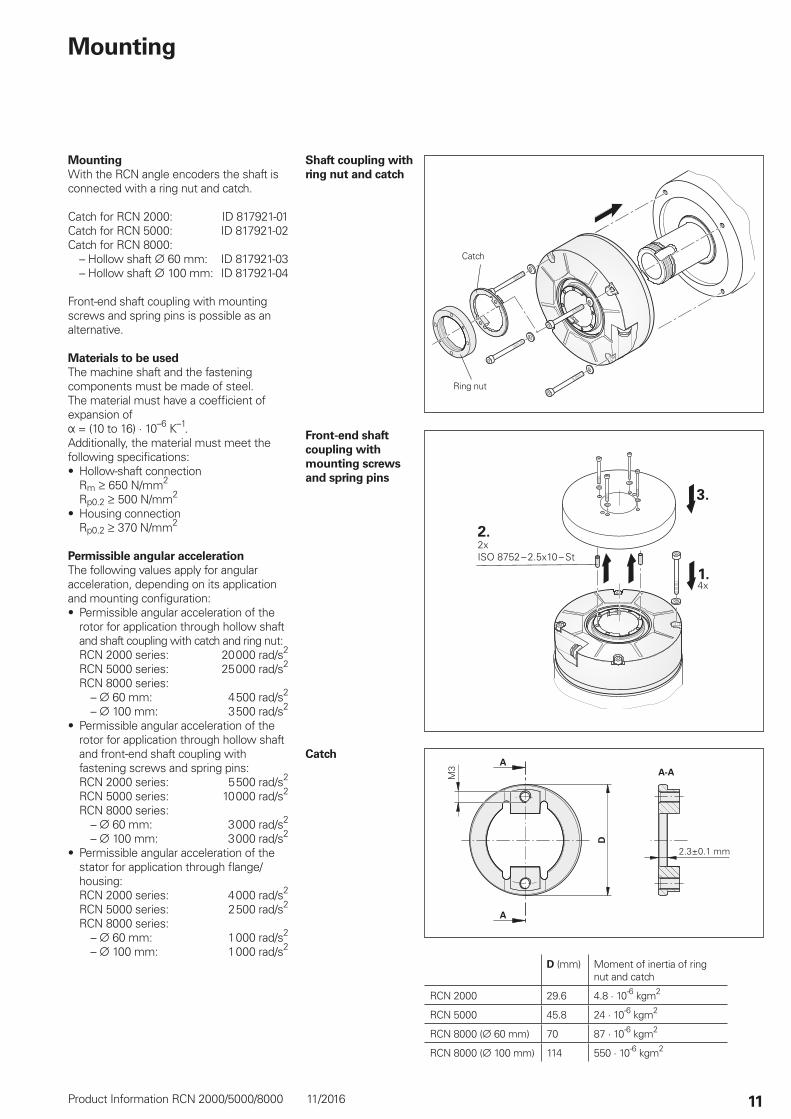
MountingWith the RCN angle encoders the shaft is connected with a ring nut and catch.
Catch for RCN 2000: ID 817921-01Catch for RCN 5000: ID 817921-02Catch for RCN 8000: – Hollow shaft 60 mm: ID 817921-03 – Hollow shaft 100 mm: ID 817921-04
Front-end shaft coupling with mounting screws and spring pins is possible as an alternative.
Materials to be usedThe machine shaft and the fastening components must be made of steel. The material must have a coefficient of expansion ofÞ = (10 to 16) · 10–6 K–1. Additionally, the material must meet the following specifications:• Hollow-shaft connection
Rm 650 N/mm2 Rp0.2 500 N/mm2
• Housing connection Rp0.2 370 N/mm2
Permissible angular accelerationThe following values apply for angular acceleration, depending on its application and mounting configuration:• Permissible angular acceleration of the
rotor for application through hollow shaft and shaft coupling with catch and ring nut: RCN 2000 series: 20 000 rad/s2 RCN 5000 series: 25 000 rad/s2 RCN 8000 series: – 60 mm: 4 500 rad/s2 – 100 mm: 3 500 rad/s2
• Permissible angular acceleration of the rotor for application through hollow shaft and front-end shaft coupling with fastening screws and spring pins: RCN 2000 series: 5 500 rad/s2 RCN 5000 series: 10 000 rad/s2 RCN 8000 series: – 60 mm: 3 000 rad/s2 – 100 mm: 3 000 rad/s2
• Permissible angular acceleration of the stator for application through flange/housing: RCN 2000 series: 4 000 rad/s2 RCN 5000 series: 2 500 rad/s2 RCN 8000 series: – 60 mm: 1 000 rad/s2 – 100 mm: 1 000 rad/s2
Mounting
Ring nut
Catch
D (mm) Moment of inertia of ring nut and catch
RCN 2000 29.6 4.8 · 10-6 kgm2
RCN 5000 45.8 24 · 10-6 kgm2
RCN 8000 ( 60 mm) 70 87 · 10-6 kgm2
RCN 8000 ( 100 mm) 114 550 · 10-6 kgm2
Front-end shaft coupling with mounting screws and spring pins
Shaft coupling with ring nut and catch
Catch

����������������������������������������������������������� ���� ���������������� ����������� ��������� �����������������������������
����������������
Pin layout8-pin coupling, M12 15-pin D-sub connector
Voltage supply Absolute position values
8 2 5 1 3 4 7 6
1 9 2 11 5 8 14 15
UP Sensor UP 0 V Sensor 0 V DATA DATA CLOCK CLOCK
Brown/Green Blue White/Green White Gray Pink Violet Yellow
Cable shield connected to housing; UP = power supply voltageSensor: The sensor line is connected in the encoder with the corresponding power line.Vacant pins or wires must not be used!
1079323 · 02 · A · 02 · 11/2016 · PDF
This Product Information supersedes all previous editions, which thereby become invalid. The basis for ordering from HEIDENHAIN is always the Product Information valid when the contract is made.
Please note the following documents:Adhere to the information in the following documents to ensure the correct and intended operation of the encoder:• Catalog: Angle Encoders with Integral Bearing 591109• Mounting Instructions RCN 2310/2510 765742
RCN 5310/5510 765743 RCN 8310/8510 ( 60 mm) 765744 RCN 8310/8510 ( 100 mm) 765745
• Technical Information: Safety-Related Position Measuring Systems 596632For implementation in a control:• Specification for Safe Control 533095For catalogs, brochures and Product Information Sheets, visit www.heidenhain.de.
Electrical connection
Connecting cablesPUR adapter cable 4.5 mm; [4 × 2 × 0.14 mm2]; AP = 0.14 mm2
Complete with 8-pin M12 coupling (male) 679671-xx
Complete with 15-pin D-sub connector (female)
735987-xx
PUR connecting cables 6 mm; [4 × 0.14 mm2 + 4 × 0.34 mm2]; AP = 0.34 mm2
Complete with 8-pin M12 connector (female) and 8-pin M12 coupling (male)
368330-xx
Complete with 8-pin M12 connector (female) and 15-pin D-sub connector (female)
533627-xx
Complete with 15-pin connector (female) and 15-pin coupling (male)
524599-xx
AP: Cross section of power supply lines: Cable diameter (for bend radii, see catalog Interfaces of HEIDENHAIN Encoders)Note for safety-related applications: Only completely assembled HEIDENHAIN cables are qualified.Be sure to exchange connectors or modify cables only after consultation with HEIDENHAIN Traunreut.For more cables, see the Angle Encoders with Integral Bearing catalog


