72
Product Information

Product Information


3XLERPLATE® steel Product Information
Contents
1. THE XLERPLATE® STEEL STORY
1.1 A long and proud heritage .................................................................................... 6
1.2 Producing the best ................................................................................................ 8
1.3 The Plate Mill ....................................................................................................... 10
1.4 The Hot Strip Mill ................................................................................................. 12
2. PRODUCT REFERENCE STANDARDS
2.1 General specifi cations .......................................................................................... 16
2.2 Boiler and pressure vessel grades ....................................................................... 22
2.3 Tolerances ............................................................................................................. 30
3. TECHNICAL INFORMATION
3.1 Flame cutting ........................................................................................................ 42
3.2 Plasma cutting ...................................................................................................... 44
3.3 Laser cutting ......................................................................................................... 45
3.4 Corrosion prevention ............................................................................................ 46
3.5 Forming and bending ............................................................................................ 48
3.6 Welding ................................................................................................................ 54
3.7 Ultrasonic testing AS 1710 .................................................................................. 58
3.8 Marking and identifi cation of XLERPLATE® steel products .................................. 62
3.9 XLERPLATE® steel order checklist ........................................................................ 64
3.10 XLERPLATE® steel enquiries.................................................................................. 66


The XLERPLATE®
steel story

6 XLERPLATE® steel Product Information
The roots of BlueScope Steel Limited and the evolution of XLERPLATE® steel are entwined in the foundation of The Broken Hill Proprietary Company Limited (BHP) established in 1885, to mine silver, lead and zinc in far western New South Wales. By 1915, the company had moved into steelmaking, opening a works at Newcastle to meet Australia’s growing demand for steel products.
The modern BlueScope Steel has evolved from the union of BHP with two other pioneer companies in the Australian steel industry, John Lysaght (Australia) Pty Ltd and Australian Iron & Steel Limited.
In 1928, Australian Iron & Steel Limited (AI&S) was formed to operate a steelworks at Port Kembla in New South Wales. AI&S was acquired by BHP in 1935 and that steelworks has grown to become one of the world’s most successful and effi cient steel plants. The quality of its products, including XLERPLATE® steel, has contributed to BlueScope Steel’s globally competitive position.
BEST PRACTICE
From the outset of its involvement in the steel industry, BHP had international focus. Exports began in the fi rst year of steel production and the company has benchmarked itself against world’s best practice ever since.
John Lysaght (Australia) Pty Ltd, an innovator in steel coating and painting technology, became a wholly owned subsidiary in 1979 and New Zealand Steel was acquired in 1989.
Excess global steelmaking capacity caused BHP to close the Newcastle Steelworks in 1999 and to redouble its efforts to become a more efficient, cost-effective supplier to local markets.
A long and proud heritage1.1

7XLERPLATE® steel Product Information
A NEW BEGINNING
In March 2001, BHP announced twomajor decisions: that it was merging with the Anglo-African mining house Billitonplc to form a dual-listed company called BHP Billiton; and that BHP Steel was to be spun out as a separate Australian publicly listed company.
BHP Steel was listed on the Australian Stock Exchange on 15 July 2002 and adopted the new name, BlueScope Steel in November 2003, not long after it had launched the brand name XLERPLATE®
steel for its range of high quality hot rolled plate steel.
ONGOING EXPANSION
In April 2004, BlueScope Steel acquired Butler Manufacturing in the United States. Founded in 1901, Butler Manufacturing is today the leading designer and producer of pre-engineered buildings in North America and China. Butler is based in Kansas City and sells through 4,000 independent dealers and contractors, and through strategic alliances with other corporations.
In 2007, BlueScope Steel acquired the metal distribution assets of the Smorgon Steel Group and transformed them into the BlueScope Distribution business, which operates a unique national chain of 50 processing and distribution centres.
Today, BlueScope Steel is Australia’s largest steel company, manufacturing around fi ve million tonnes of fl at steel products each year. This includes the production of more than 450,000 tonnes of XLERPLATE® steel which is used in literally thousands of applications; from bridge girders to ship building and water reservoir construction, to wind towers, mining equipment and pressure vessels.
1.1A long and proud heritage

8 XLERPLATE® steel Product Information
1.2 Producing the best
Each year the Port Kembla Steelworks’ blast furnaces produce more than fi ve million tonnes of liquid iron, the raw material for steelmaking.
To produce XLERPLATE® steel and the other steel products that Australian and export markets rely on, the liquid iron is combined with scrap steel in a basic oxygen steelmaking (BOS) vessel, where oxygen and fl uxes remove impurities.
The liquid steel produced by this process is treated to incorporate the specifi c properties required, then transferred to a continuous slab casting process, where liquid steel is poured into a mould, and continuously withdrawn and cut to the length required for processing.
One measure of the quality of steel produced by BlueScope Steel using this process is its ‘tier one’ grading by export customers for slabs.
Steel sold under the XLERPLATE® brand is produced by the Port Kembla Plate Mill, a facility which has undergone several major upgrades in its 45-year history as a key supplier to Australian industry.
Exceptional quality, service and support are the benchmarks of XLERPLATE® steel supplied by BlueScope Steel. This is achieved by a combination of advanced
manufacturing technology, overseen by a highly skilled workforce and supported by technical and administrative teams with a total customer focus.
QUALITY ASSURANCE
BlueScope Steel holds ISO 9001 Quality Management System Accreditation and all XLERPLATE® steel is tested to ensure that customers receive steel that is consistent with their order. If the product is intended for critical applications, a more detailed ‘off-line’ inspection can be arranged.
TEST CERTIFICATES
Comprehensive test certifi cates are provided for all XLERPLATE® steel products and BlueScope Steel quality control laboratories are registered with the National Association of Testing Authorities (NATA). An authorised inspector can witness mechanical testing on request and endorse the test certifi cate.
LOCAL FLEXIBLE SUPPLY
For steel-intensive projects BlueScope Steel collaborates with its distributors and major customers to provide ‘fl owed’ deliveries of XLERPLATE® steel to meet fabrication needs and to reduce project costs by minimising sorting, handlingand storage.

9XLERPLATE® steel Product Information
ORDERING ONLINE
To simplify the process of ordering steel and doing business with BlueScope Steel, www.bluescopesteelconnect.com provides online access 24 hours a day, seven days a week.
Our OrderIntegrator® system for single point data entry delivers time savings, productivity enhancements and reduced error potential, while giving more control over orders.
At www.bluescopesteelconnect.com customers can access their repeat order catalogue, select items, quantities and delivery timing required, then submit their order. Importantly an Order Status facility on the site allows the progress of ordersto be monitored through the post-production process.
Other practical advantages offered by www.bluescopesteelconnect.com include real-time invoices and statements, printable test certifi cates (including historical certifi cates) and the ability to check the despatch history of purchases.
TECHNICAL EXCELLENCE
XLERPLATE® steel is backed by a level of support which is simply not available for steel sourced elsewhere. An experienced technical team can provide support for XLERPLATE® steel related projects.
For more information about our free technical support service, call BlueScope Steel Direct on 1800 800 789 within Australia.
STEEL RECYCLING
Scrap steel is an important ingredient in all steel produced. The Blast Furnace-BasicOxygen Steelmaking (BF-BOS) process undertaken at Port Kembla Steelworks, and the Electric Arc Furnace (EAF)production method, both require scrap steel. This means that steel is one of the many materials in the world to have a guaranteed recycled content.
Steel production can be limited by scrap availability. BF-BOS recycled content proportions may also be limited by the availability of scrap, however, there are also technical limitations. These factors result in the proportion of scrap material used in the BF-BOS process by BlueScope in Australia is on average 17-20%.
From a sustainability point of view, the proportion of steel recovered for recycling at the end of each usage-phase is more relevant than the recycled content of any given product at a particular point in time. In sustainability terms, no goods or service should be evaluated by a single metric – the full life cycle of the product should be taken into account; including all positive and negative effects on the environment, society and economy, from cradle to grave.
Producing the best 1.2

10 XLERPLATE® steel Product Information
The high quality hot rolled XLERPLATE®
steel is produced at the Port Kembla Steelworks’ Plate Mill – a key supplier to Australian industry and a facility which has undergone several major upgrades in its 45-year history.
The 3,200mm Plate Mill is the only wide Plate Mill in Australia. It converts slabs produced at the slab caster into fi nal customer-specified XLERPLATE® steel dimensions and is capable of rolling thicknesses from 5mm to 150mm and widths from 1,200mm to 3,200mm.
Slabs produced by the Steelworks’ continuous caster for the Plate Mill are put through a 1,200 degrees Celsius reheat furnace which is fed by gases produced as by-products elsewhere in the steel making process. Reheating is tightly integrated with the Plate Mill’s rolling operations to give maximum operator control.
Blasting with high pressure water removes surface scale from the reheated slabs and prepares them for the rolling process. In the fi rst stage of the rolling process the slab undergoes a series of passes through a reversing mill. During this stage of rolling the required width is obtained. Once the correct width is obtained and the slab has been rolled to a predetermined intermediate thickness, the slab is then sent to a second reversing mill to complete the rolling process.
A series of passes through the second reversing mill results in XLERPLATE® steel of the required dimensions, including the fi nal thickness. Following rolling, the XLERPLATE® steel passes through a hot leveller to ensure it meets the required fl atness standards.
The rolling parameters, such as temperature and the amount of thickness reduction per pass, are carefully controlled and monitored in the production of XLERPLATE® steel to ensure all specifi ed properties are obtained.
After cooling, the XLERPLATE® steel is sent to the processing area, where it is cut to the required size. Cutting of test pieces and inspection is carried out at this stage.
1.3 The Plate Mill

11XLERPLATE® steel Product Information

12 XLERPLATE® steel Product Information
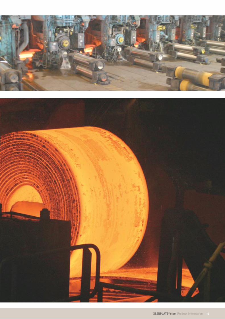
The Port Kembla Steelwork’s Hot Strip Mill produces premium coil for fabrication. Coil from the Hot Strip Mill is available in widths from 900mm to 1,500mm and 1.6mm to 12mm thick, in grades conforming to AS/NZ 1594/2002.
A special range of cut-to-length structural plate grades produced by the Hot Strip Mill is marketed under the XLERPLATE LITE®
steel brand designation.
In the Hot Strip Mill, slabs produced in the slabmaking operations are reheated to temperatures around 1,200 degrees Celsius and then hot rolled with highly accurate dimensional control to the desired customer specifi cations. During this process the slab which may have been up to 12.5m in length will become coiled strip up to 2km long.
The Hot Strip Mill, housed in Australia’s longest industrial building, received a $100 million upgrade in 2006 to incorporate a second slab reheating furnace.
After reheating, the slab is descaled with high pressure sprays to remove the oxide generated during reheating. It then enters the Reversing Roughing Mills where through a series of passes it is reduced in thickness from the original 230mm to a transfer bar thickness of around 30mm suitable for the fi nishing stands.
During the roughing process, heavy edger rolls with hydraulic, automatic width control, reduce and accurately control the width. This process uses adapted computer modelling with feed forward capabilities to ensure that the width within each coil is fi nely controlled.
Final reduction occurs in the six fi nishing stands. The strip is accurately rolled to the ordered thickness with the aid of adapted computer models, hydraulic gauge control and closed loop profi le, crown (transverse thickness) and fl atness control.
Much of the steel produced by the Hot Strip Mill is used in the production of BlueScope Steel’s premium coated or painted brands such as COLORBOND®,ZINCALUME®, DECKFORM® and TRUECORE® steels.
The same Hot Strip Mill processes also produce steel which meets the exacting standards of the PIPESTEEL™ andTUBEFORM® steel specifi cations.
1.4 The Hot Strip Mill
13XLERPLATE® steel Product Information
0.1Section Heading Here


Product reference standards

16 XLERPLATE® steel Product Information
BlueScope Steel guarantees the quality of its XLERPLATE® steel and stands behind its products by certifying their compliance with independently established Standards.
Unless otherwise agreed, products are supplied in accordance with AS/NZS 3678 (Structural steel – hot rolled plates and fl oor plates), AS/NZS 1594 (Hot rolled steel fl at products), AS 1548 (Steel plates for pressure equipment) and AS/NZS 1365 (Tolerances for flat-rolled steel products).
The Standards cover such matters as testing, inspection, certifi cation procedures and dimensional tolerances.
Information about Standard specifi cations was current at the date of publication.
XLERPLATE® STEEL ENGINEERINGAND STRUCTURAL GRADES
AS/NZS 3678, AS/NZS 1594
These Standards specify a range of engineering and structural grades defi ned by mechanical properties and chemical composition. These fully-killed, fine grained Carbon-Manganese and Carbon-Manganese-Niobium steels have excellent forming and welding characteristics.
XLERPLATE® steel structural grade is made to the Australian Standard AS/NZS 3678 in grades 250, 350, 400 and 450. Some XLERPLATE® steel structural grades are also listed as part of the American Welding Society’s AWS B2.1 Standard, one oftwo key reference documents in theUnited States for weld procedure and performance qualifi cations.
XLERPLATE LITE® steel structural grades such as HA250 and HA350 are made to the Standard AS/NZS 1594.
For technical assistance call BlueScope Steel Direct on 1800 800 789 within Australia, or refer to www.xlerplate.com.au
General specifi cations2.1
17XLERPLATE® steel Product Information
2.1General specifi cations
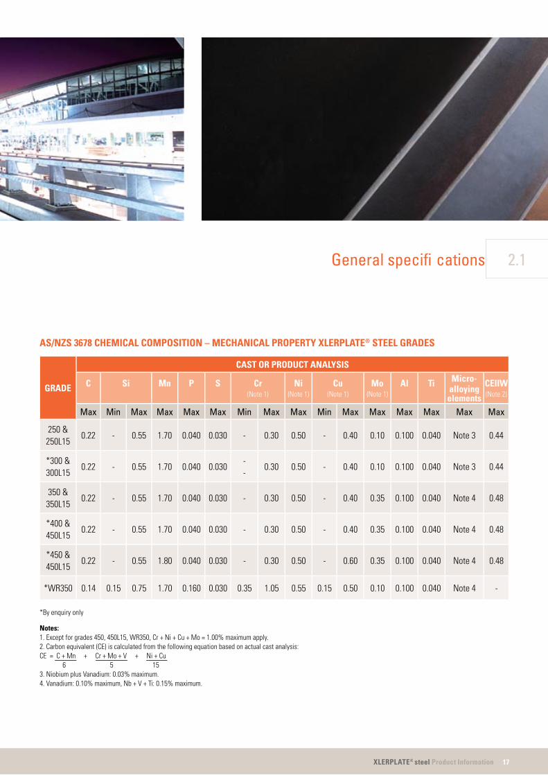
AS/NZS 3678 CHEMICAL COMPOSITION – MECHANICAL PROPERTY XLERPLATE® STEEL GRADES
GRADE
CAST OR PRODUCT ANALYSIS
C Si Mn P S Cr(Note 1)
Ni(Note 1)
Cu(Note 1)
Mo(Note 1)
Al Ti Micro-alloying
elements
CEIIW(Note 2)
Max Min Max Max Max Max Min Max Max Min Max Max Max Max Max Max
250 &250L15
0.22 - 0.55 1.70 0.040 0.030 - 0.30 0.50 - 0.40 0.10 0.100 0.040 Note 3 0.44
*300 &300L15
0.22 - 0.55 1.70 0.040 0.030--
0.30 0.50 - 0.40 0.10 0.100 0.040 Note 3 0.44
350 &350L15
0.22 - 0.55 1.70 0.040 0.030 - 0.30 0.50 - 0.40 0.35 0.100 0.040 Note 4 0.48
*400 &450L15
0.22 - 0.55 1.70 0.040 0.030 - 0.30 0.50 - 0.40 0.35 0.100 0.040 Note 4 0.48
*450 &450L15
0.22 - 0.55 1.80 0.040 0.030 - 0.30 0.50 - 0.60 0.35 0.100 0.040 Note 4 0.48
*WR350 0.14 0.15 0.75 1.70 0.160 0.030 0.35 1.05 0.55 0.15 0.50 0.10 0.100 0.040 Note 4 -
*By enquiry only
Notes:1. Except for grades 450, 450L15, WR350, Cr + Ni + Cu + Mo = 1.00% maximum apply.2. Carbon equivalent (CE) is calculated from the following equation based on actual cast analysis:CE = C + Mn + Cr + Mo + V + Ni + Cu 6 5 153. Niobium plus Vanadium: 0.03% maximum.4. Vanadium: 0.10% maximum, Nb + V + Ti: 0.15% maximum.
18 XLERPLATE® steel Product Information
General specifi cations2.1
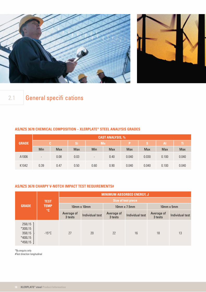
AS/NZS 3678 CHEMICAL COMPOSITION – XLERPLATE® STEEL ANALYSIS GRADES
GRADE
CAST ANALYSIS, %
C Si Mn P S Al Ti
Min Max Max Min Max Max Max Max Max
A1006 - 0.08 0.03 - 0.40 0.040 0.030 0.100 0.040
K1042 0.39 0.47 0.50 0.60 0.90 0.040 0.040 0.100 0.040
AS/NZS 3678 CHARPY V-NOTCH IMPACT TEST REQUIREMENTS#
GRADETESTTEMP
°C
MINIMUM ABSORBED ENERGY, J
Size of test piece
10mm x 10mm 10mm x 7.5mm 10mm x 5mm
Average of3 tests Individual test Average of
3 tests Individual test Average of3 tests Individual test
250L15*300L15 350L15*400L15*450L15
-15°C 27 20 22 16 18 13
*By enquiry only#Test direction longitudinal

19XLERPLATE® steel Product Information
2.1General specifi cations
AS/NZS 3678 TENSILE TEST REQUIREMENTS FOR XLERPLATE® STEEL AND XLERPLATE® STEEL FLOORPLATE
GRADE
MINIMUM YIELD STRESS, MPa
Thickness, mm Minimumtensile
strengthMPa
Minimumelongationon a gauge
length of 5.65√So
%
≤ 8 > 8≤ 12
> 12≤ 20
> 20≤ 32
> 32≤ 50
> 50≤ 80
> 80≤ 100
> 100≤ 150
250250L15
280 260 250 250 250 240230240
230240
410 22**
*300300L15
320 310 300 280 280 270 - - 430 21
350350L15
360 360 350 340 340 340 *330 - 450 20
*400450L15
400 400 380 360 360 360 - - 480 18
*450450L15
450 450 450 420 400 - - -520500
1618
*WR350 340 340 340 - - - - - 450 20
*By enquiry only**Elongation testing not required for fl oorplate

20 XLERPLATE® steel Product Information
General specifi cations2.1
AS/NZS 1594 CHEMICAL COMPOSITION REQUIREMENTS FOR FORMABILITY, STRUCTURAL AND WEATHER-RESISTANT XLERPLATE LITE® STEEL GRADES
GRADE
CHEMICAL COMPOSITION (CAST OR PRODUCT ANALYSIS), %
C Si Mn P S Cr(Note 1)
Ni(Note 1)
Cu(Note 1)
Al TiMicro-
Alloyingelements
CEIIW
Max Min Max Max Min Max Max Min Max Max Min Max Max Max Max Max
HA1 0.13 - 0.03 0.50 - 0.040 0.030 - 0.15 0.15 - 0.15 0.100 0.040 Note 2 -
HA200 0.15 - 0.35 0.60 - 0.030 0.030 - 0.15 0.15 - 0.15 0.100 0.040 Note 3 0.29
HA250 0.20 - 0.35 1.20 - 0.040 0.030 - 0.25 0.25 - 0.25 0.100 0.040 Note 3 0.39
HA300 0.20 - 0.35 1.60 - 0.040 0.030 - 0.25 0.25 - 0.25 0.100 0.040 Note 3 0.39
HA350 0.22 - 0.35 1.60 - 0.040 0.030 - 0.25 0.25 - 0.25 0.100 - Note 4 0.44
HW350 0.15 0.15 0.75 1.60 0.055 0.160 0.030 0.35 1.05 0.55 0.15 0.50 0.100 - Note 4 0.54
Notes:1. For all grades other than HW350 - Molybdenum 0.05% maximum. Copper + Nickel + Molybdenum - 0.6% maximum.2. Niobium - 0.010% maximum. Niobium + Vanadium - 0.030% maximum. Boron (total) - 0.015% maximum.3. Niobium + Vanadium - 0.030% maximum.4. Vanadium - 0.10% maximum. Niobium + Vanadium + Titanium - 0.15% maximum.

21XLERPLATE® steel Product Information
2.1General specifi cations
AS/NZS 1594 TENSILE PROPERTY REQUIREMENTS FOR FORMABILITY, STRUCTURAL AND WEATHER-RESISTANTXLERPLATE LITE® STEEL GRADES
GRADE
MINIMUMUPPER YIELD
STRESSMPA
MINIMUMTENSILE
STRENGTHMPA
ELONGATION, % MIN (NOTES 1 AND 2)
Normal Thickness, mm
≤ 3 > 3
L 0=50mm L 0=80mm L 0=200mm L 0=50mm L 0=80mm L 0=200mm
HA1 (Note 3) (Note 3) - - - - - -
HA200 200 300 24 22 17 28 26 19
HA250 250 350 22 20 16 26 24 17
HA300 300 400 20 18 15 24 22 16
HA350 350 430 18 16 14 22 20 15
HW350 340 450 - - 15 - - 15
Notes:1. Lo = Original gauge length of test piece.2. Elongation testing is not required for fl oorplate.3. For design purposes, yield and tensile strengths approximate those of XLERPLATE LITE® steel structural grade HA200. For specifi c information contact BlueScope Steel Direct
on 1800 800 789.

22 XLERPLATE® steel Product Information
AS 1548
The XLERPLATE® steel range of boiler and pressure vessel grades is based on Australian Standard 1548 (Steel plates for boilers and pressure vessels). This provides for the supply of Silicon-Aluminium killed, Carbon-Manganese XLERPLATE® steel up to a maximum thickness of 100mm.
AS 1548 grades are designated in the following manner:
AS 1548 – PTYDAHLXZX
P = Pressure vessel steel
T = Tensile strength specifi ed
Y = Specifi ed minimum tensile strength
D = Delivery condition as follows:
N – XLERPLATE® steel supplied normalised in temperature range 870°C – 930°C after fi nal rolling.
NR –XLERPLATE® steel supplied in normalised rolled condition.
T – XLERPLATE® steel supplied in the TMCR (thermo mechanical control rolled) process. This results in low temperature impact properties equivalent to those of normalised material and may be used as an alternative process to normalising. T rated XLERPLATE® steel is not generally suitable for hot forming.
NRA = Testing required in the simulated normalised condition (only applies for the NR delivery condition).
H = Indicates that an elevated temperature tensile property is specifi ed. The required test temperature must be specifi ed.
LX = Indicates that a low temperature impact test is specifi ed. The temperature is inserted in place of (X), e.g. L50 indicates impact testing at minus 50°C.
ZX = Indicates that a through-thickness tensile test is required (Z) together with a percentage reduction of area (X), e.g. Z25 for 25% minimum average reduction of area.
All test pieces are subject to a simulated stress relieving treatment at a temperature of 600°C +/- 20°C for a period of 3 hours (approx.) before testing.
The chemical composition and mechanical test requirements for the AS 1548 grades are shown on the following pages. A current version of the Standard should be consulted to confi rm the values given, and to obtain detailed specifi cation requirements.
Boiler and pressure vessel grades2.2

23XLERPLATE® steel Product Information
2.2Boiler and pressure vessel grades
ORDERING OF XLERPLATE® STEELBOILER AND PRESSURE VESSELGRADES
Special care is required in defi ning all requirements for pressure vessel steel grades. The information which follows is intended to assist customers in the preparation of enquiries and orders.
You should always refer to the original specifi cation and use BlueScope Steel’s Order Checklist on page 64 to assist with this process.
Pressure vessel grades, apart from those in the XLERPLATE® steel standard range are by enquiry to ensure grade, size and supplementary specifi cations are available.
The following tables show the chemical compositions and mechanical test requirements for AS 1548 grades.
THROUGH THICKNESS TESTEDXLERPLATE® STEEL
This special soundness ‘Z’ quality XLERPLATE® steel is a lamellar tear-resistant grade, with guaranteed through-thickness tensile properties, often specifi ed for critical applications including some pressure vessels.
Lamellar tearing is a form of cracking in a plane parallel to the plate surface in the vicinity of highly restrained welded joints. Such joints are likely to be found where plate is used in the fabrication of structures such as offshore platforms, high-rise buildings, bridges, large draglines and open-cut dredging machines.
Three factors contribute to the occurrence of lamellar tearing – structural restraint, joint design and through-thickness ductility of the plate.
BlueScope Steel supplies lamellar tear-resistant steels to through-thickness tensile requirements subject to availability. Steels which are to be supplied to through-thickness tensile requirements are made to a high standard of internal cleanliness and have a low sulphur level, generally 0.01% or less, and may be treated with calcium for inclusion shape control.
Supply to a minimum through-thickness reduction of area can be negotiated forany structural or pressure vessel product in the XLERPLATE® steel range. XLERPLATE®
steel is supplied ultrasonically testedto AS 1710 Level 2 Standard as a mandatory requirement.

24 XLERPLATE® steel Product Information
PRODUCT ANALYSIS
Product analysis is available on enquiry (at additional cost) and is carried out on a sample obtained from the rolled XLERPLATE® steel. Where product analysis is specifi ed by the customer for AS 1548 grades, it is normal practice to report all elements listed in the relevant specifi cation.For other specifi cations, or where variation from this practice is required, this should be noted when ordering.
PRODUCT SPECIFICATIONS
The supply of NATA endorsed test certifi cates for XLERPLATE® steel products is standard practice. Supply of standard test certifi cates are available at no extra cost. The identity of the XLERPLATE® steel should be verifi ed against order and test documents as soon as practicable after delivery.
Normalising
Normalising is a heat treatment process where the steel is heated to 870°C – 930°C(austenitised) for approximately 60 minutes per 25mm of thickness and air-cooled. The process refi nes the grain size to improve uniformity in microstructure and to remove stresses produced in the steel during rolling.
For pressure vessel grades (AS 1548) where it is intended to normalise XLERPLATE®
steel as part of the fabrication procedure, XLERPLATE® steel may be ordered in the as-rolled condition with tests to be carried out on normalised test pieces (NRA Condition). Normalising temperature depends on the steel grade and users should refer to test certifi cates for the actual temperature used in normalising of XLERPLATE® steel or test pieces.
Where customers order NRA grade XLERPLATE® steel they must ensure that the appropriate heat treatment is carried out. It is recommended that additional samples be taken for quality assurances after normalising.
Dimensions of normalised XLERPLATE® steel are limited by the capacity of our normalising contractor and by other production factors such as lifting capability. Please refer to the XLERPLATE® steel Size Schedule appropriate to the steel grade concerned.
Boiler and pressure vessel grades2.2

25XLERPLATE® steel Product Information
Controlled rolling
The amount of deformation and the temperature at which it occurs are controlled during this rolling process, which is designed to produce a fine-grained microstructure with the desired mechanical properties.
The mechanical properties obtained by controlled rolling are generally lost ifthe steel is reheated above 620°C.Customers should consult XLERPLATE®
steel Technical Service on 1800 800 789 prior to hot forming these grades.
Normalised rolling
In this process, the fi nal deformation is carried out in a specifi c temperature range which leads to a material condition equivalent to that obtained after normalising, so that the specifi ed values of the mechanical properties are retained even after normalising.
2.2Boiler and pressure vessel grades
26 XLERPLATE® steel Product Information
Boiler and pressure vessel grades2.2
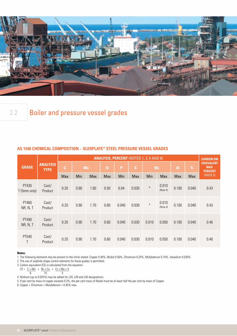
AS 1548 CHEMICAL COMPOSITION – XLERPLATE® STEEL PRESSURE VESSEL GRADES
GRADEANALYSIS
TYPE
ANALYSIS, PERCENT (NOTES 1, 2, 5 AND 6) CARBON IIWEQUIVALENT
MAX.PERCENT(NOTE 3)
C Mn Si P S Nb Al Ti
Max Min Max Max Min Max Min Max Max Max
PT430T (5mm only)
Cast/Product
0.20 0.80 1.60 0.50 0.04 0.030 *0.010(Note 4) 0.100 0.040 0.43
PT460NR, N, T
Cast/Product
0.20 0.90 1.70 0.60 0.040 0.030 *0.010(Note 4) 0.100 0.040 0.43
PT490NR, N, T
Cast/Product
0.20 0.90 1.70 0.60 0.040 0.030 0.010 0.050 0.100 0.040 0.46
PT540T
Cast/Product
0.20 0.90 1.70 0.60 0.040 0.030 0.010 0.050 0.100 0.040 0.46
Notes:1. The following elements may be present to the limits stated: Copper 0.40%, Nickel 0.50%, Chromium 0.25%, Molybdenum 0.10%, Vanadium 0.030%2. The use of sulphide shape control elements for these grades is permitted.3. Carbon equivalent (CE) is calculated from the equation:
CE = C + Mn + Ni + Cu + Cr + Mo + V 6 15 54. Niobium (up to 0.025%) may be added for L20, L40 and L50 designations.5. If per cent by mass of copper exceeds 0.3%, the per cent mass of Nickel must be at least half the per cent by mass of Copper.6. Copper + Chromium + Molybdenum = 0.45% max.

27XLERPLATE® steel Product Information
2.2Boiler and pressure vessel grades
AS 1548 TENSILE REQUIREMENTS FOR XLERPLATE® STEEL PRESSURE VESSEL GRADES
TYPE ANDGRADE
MINIMUM UPPER YIELD STRESS VALUE, MPaTENSILE
STRENGTHMPa
MINIMUM ELONGATION‘A’ AS A PERCENTAGE
PROPORTION OF GAUGELENGTH OF 5.65 √So
%
Thickness, mm
≤ 16 > 16 ≤ 40 > 40 ≤ 80 > 80 ≤ 100
PT430T (5mm only)
300 280 270 250 430 to 550 22
PT460NR, N, T
305 295 275 265 460 to 580 21
PT490NR, N, T
360 340 330 320 490 to 610 20
PT540T
450 420 – – 540 to 670 18

28 XLERPLATE® steel Product Information
Boiler and pressure vessel grades2.2
AS 1548 CHARPY V-NOTCH IMPACT TEST REQUIREMENTS FOR XLERPLATE® STEEL PRESSURE VESSEL GRADES#
TYPE ANDGRADE
IMPACTDESIGNATION
TESTTEMPERATURE
°C
MINIMUM ABSORBED ENERGY, J
Size of test piece
10mm x 10mm 10mm x 7.5mm 10mm x 5mm
Individualtest
Average of3 tests
Individualtest
Average of3 tests
Individualtest
Average of3 tests
PT430T (5mm only)
L0 0 – – – – 16 22
PT460NR
L0 0 38 51 29 40 27 34
PT460NR, R, T
L20L40L50
-20-40-50
353331
474542
282725
383634
252322
333230
PT490NR, N, T
L20L40L50
-20-40-50
433331
554542
352725
443634
302322
393230
PT540T
L20L40L50
-20-40-50
433331
554542
352725
443634
302322
393230
Note:For thickness less than 7mm, full thickness impact tests may be negotiated.# Test Direction Longitudinal
Where no impact designation is specifi ed, the base grades for PT430 and PT460 shall meet a minimum individual test requirement of 23 Joules and a minimum average of three test requirements of 31 Joules when tested at 0˚C. The base grades for PT490 shall meet a minimum individual test requirement of 43 Joules and a minimum average of three test requirements of 55 Joules when tested at -20˚C.
29XLERPLATE® steel Product Information
2.2Boiler and pressure vessel grades
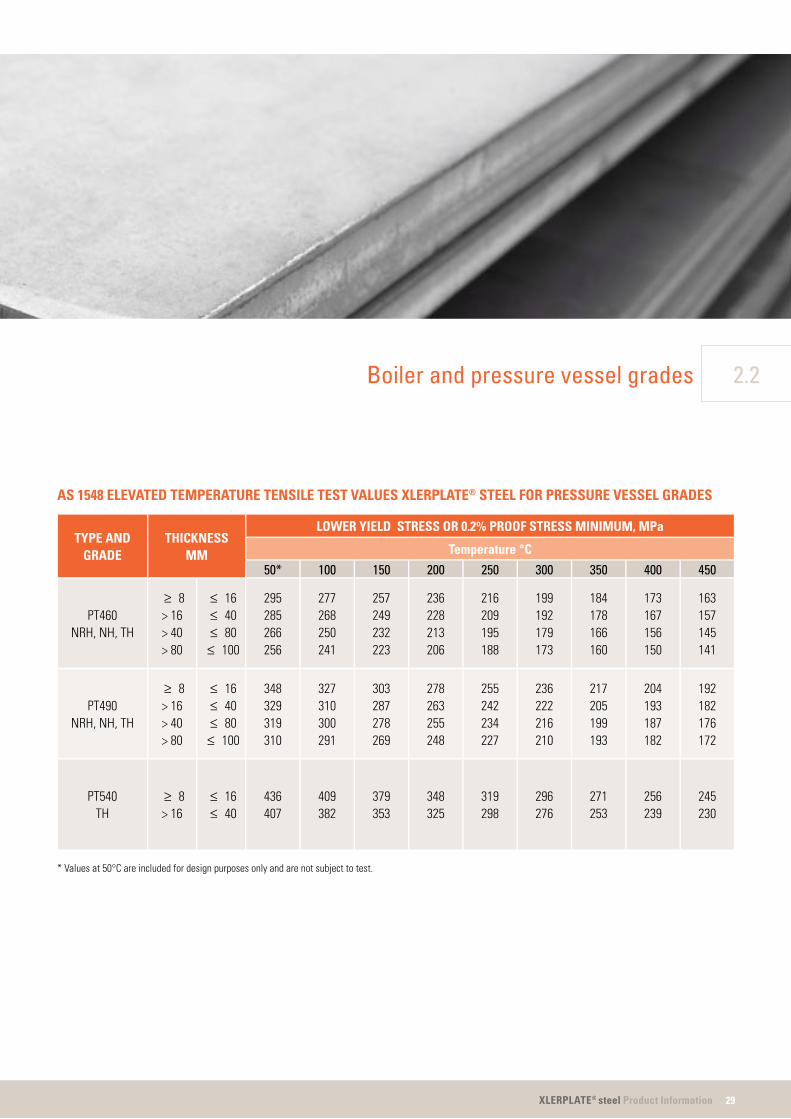
AS 1548 ELEVATED TEMPERATURE TENSILE TEST VALUES XLERPLATE® STEEL FOR PRESSURE VESSEL GRADES
TYPE ANDGRADE
THICKNESSMM
LOWER YIELD STRESS OR 0.2% PROOF STRESS MINIMUM, MPa
Temperature °C
50* 100 150 200 250 300 350 400 450
PT460NRH, NH, TH
≥ 8> 16> 40> 80
≤ 16≤ 40≤ 80
≤ 100
295285266256
277268250241
257249232223
236228213206
216209195188
199192179173
184178166160
173167156150
163157145141
PT490NRH, NH, TH
≥ 8> 16> 40> 80
≤ 16≤ 40≤ 80≤ 100
348329319310
327310300291
303287278269
278263255248
255242234227
236222216210
217205199193
204193187182
192182176172
PT540TH
≥ 8> 16
≤ 16≤ 40
436407
409382
379353
348325
319298
296276
271253
256239
245230
* Values at 50°C are included for design purposes only and are not subject to test.

30 XLERPLATE® steel Product Information
TOLERANCES FORXLERPLATE® STEEL ANDXLERPLATE® STEEL FLOORPLATE
This section specifi es the manufacturing tolerances for XLERPLATE® steel and XLERPLATE® steel fl oorplate over 4.5mm thick that has been hot rolled on a reversing mill. Unless otherwise indicated, tolerances apply to 100% of product supplied.
EDGE CAMBER TOLERANCES
Edge camber will be limited to ensurethat the dimensions of the ordered XLERPLATE® steel are within the delivered size. If agreed to at the time of ordering, edge camber will be limited to 0.2% of the actual length of the plate for a trimmed edge and 0.3% of the actual length of the plate for an untrimmed edge.
Out-of-square tolerances
For all sizes the cut lengths shall be such that XLERPLATE® steel conforming to the ordered nominal dimensions can be obtained.
Flatness tolerances
Tolerances for fl atness vary with the nominal thickness of the product. Detailsare provided in AS/NZS1365 and shown over the page.
TOLERANCES FORXLERPLATE LITE® STEEL
This section specifi es the manufacturing tolerances for hot rolled XLERPLATE LITE®
steel rolled on a continuous mill in thicknesses up to 12mm and widths up to 1,800mm. Unless otherwise indicated, tolerances apply to 100% of product supplied.
Edge camber tolerances
When measured in accordance with the procedure described previously, the maximum deviation of the side edge from a straight edge for hot rolled XLERPLATE LITE®
steel in all edge conditions will not exceed 0.4% of the actual length.
Out-of-square tolerances
For all sizes the cut lengths shall be such that sheets or plates conforming to the ordered nominal dimensions can be obtained. When measured in accordance with the procedure described previously, the out-of-squareness of a cut length from trimmed-edge steel strip will not exceed 1.0%.
2.3 Tolerances

31XLERPLATE® steel Product Information
2.3Tolerances
FLATNESS
To measure fl atness, the product, resting under its own weight, is placed on a fl at horizontal surface in such a manner that any deviation from fl atness is in the centre, not at the ends.
Deviations from fl atness are measured by allowing a straight edge to rest on at least two points on the product surface and then measuring the distance between the product and the straight edge (Diagram A).
L
H
Only that portion between two consecutive points of contact is taken into consideration. The straight edge may be placed in any direction. Where two points of contact do not exist, the deviation may be determined by measuring the distance between the fl at horizontal surface and the bottom surface of the product (Diagram B).
W
L
H
STEEPNESS RATIO
This is an alternative method for expressing fl atness. The product resting under its own weight is placed on a fl at horizontal surface with the depression to be measured facing upwards. The steepness ratio, expressed as a percentage, is calculated by determining the maximum distance between the product surface and straight edge in accordance with the procedures specifi ed. (Illustrated in Diagrams A and B), then applying the following equation:
Steepness ratio = H x 100% Lwhere:
H = deviation from fl atness (wave height) in millimetres
L = length of sheet between two points of contact in millimetres
DIAGRAM B: Where two points of contact do not exist.
DIAGRAM A: Between two points of contact.

32 XLERPLATE® steel Product Information
2.3 Tolerances
OUT-OF-SQUARENESS
The deviation from squareness of a length cut from trimmed edge steel strip is measured by scribing a line perpendicular to the trimmed edge adjacent to the cut. The out-of-squareness is expressed by a percentage of the measured value of deviation from square divided by the nominal width (Diagram C).
W
UU
DIAGRAM C: Measurement of out-of-squareness.
Out-of-squareness is expressed as:
U x 100%Wwhere:
W = nominal widthU = deviation from square
EDGE CAMBER
To measure edge camber the product is laid on a fl at horizontal surface and a straight edge placed on the concaveside edge. The maximum distancebetween the side edge and the straight edge (Wc) is then measured (Diagram D).Camber is expressed as a percentage of the measured value divided by the length of sheet.
Wc
W
L
Straight edge
TOP VIEW
DIAGRAM D: Measurement of edge camber.
The camber is calculated from the following equation C = Wc x 100% Lwhere:
C = camber in percentageW = width of sheetWc = linear measurement of camberL = length of sheet in mm

33XLERPLATE® steel Product Information
FACTORS INFLUENCING FLATNESS
Continuous mill product
The inability of a plate or sheet cut from hot rolled coil to lie fl at on a smooth horizontal surface is due to one or more of the following conditions:
the edges of the strip elongate more than the centre of the strip during rolling.
when the centre of the strip, in the rolling direction, elongates more than the edges.
occurs as the result of a temperature differential in the product, which on cooling assumes the curvature of the coil. It can be removed by a fl attening operation using larger diameter rollers. Reverse longbow can be inducedinto steel strip by incorrect set-upand operation of fl attening andlevelling equipment.
result of cooling effects associatedwith the rolled coil which is thicker in the centre than at the edges. The resultant strip will have a cross or transverse bow when the coil cools. Crossbow can be removed by afl attening or levelling operation.
All four of these conditions can result from incorrect fl attening and levelling operations involving set-up, equipment or operator inexperience.
The presence of edge wave or centre buckle is directly associated with the rolling procedures used when rolling slab into a coil. It is not possible to remove edge wave and centre buckle when coils have been levelled and cut to length without subjecting the coil product to additional processing such as skin passing or stretcher levelling.
2.3Tolerances

34 XLERPLATE® steel Product Information
2.3 Tolerances
THICKNESS TOLERANCES FOR XLERPLATE® STEEL AND XLERPLATE® STEEL FLOORPLATE AS/NZS 3678
SPECIFIEDWIDTH
MM
THICKNESS TOLERANCE, PLUS OR MINUS
Nominal plate thickness
> 4.5≤ 6
> 6≤ 8
> 8≤ 10
> 10≤ 13
> 13≤ 18
> 18≤ 22
> 22≤ 30
> 30≤ 42
> 42≤ 63
> 63≤ 100
> 100≤ 180
≥ 600
≥ 1,000
≥ 1,600
≥ 2,100
≥ 2,700
< 1,000
< 1,600
< 2,100
< 2,700
< 3,300
0.35
0.35
0.40
0.50
0.65
0.35
0.40
0.45
0.50
0.65
0.40
0.40
0.45
0.55
0.70
0.45
0.45
0.50
0.60
0.75
0.50
0.55
0.60
0.65
0.80
0.55
0.60
0.65
0.75
0.90
0.65
0.70
0.75
0.85
0.95
0.80
0.85
0.90
1.00
1.15
1.10
1.15
1.20
1.30
1.45
1.60
1.70
1.75
1.85
1.95
2.25
2.30
2.35
2.40
2.40
The table specifi es thickness tolerances applicable to plate and fl oorplate in all edge conditions that have a specifi ed or typical minimum yield strength of 360MPa or less.For steels with a specifi ed or typical minimum yield strength greater than 360MPa, the thickness tolerance is determined by multiplying the values by a factor of 1.5. The thickness tolerance for fl oorplate applies to the unraised thickness of the plate.
LENGTH TOLERANCES FOR XLERPLATE® STEEL AND XLERPLATE® STEEL FLOORPLATE AS/NZS 3678 & AS 1548
SPECIFIED LENGTHLENGTH TOLERANCE
Specifi ed thickness
All> 4.5 < 25 > 25 ≤ 180
+30, -0 +40, -0
The table specifi es width tolerances for XLERPLATE® steel and XLERPLATE® steel fl oorplate in all edge conditions.

35XLERPLATE® steel Product Information
2.3Tolerances
THICKNESS TOLERANCES FOR XLERPLATE® STEEL PRESSURE VESSEL AS 1548
SPECIFIEDWIDTH
MM
UNDERTOLERANCE
MM
PERMISSABLE VARIATION OVER SPECIFIED THICKNESS
Specifi ed thickness
> 4.5≤ 6
> 6≤ 8
> 8≤ 10
> 10≤ 13
> 13≤ 18
> 18≤ 22
> 22≤ 30
> 30≤ 42
> 42≤ 63
> 63≤ 100
≥ 600
≥ 1,000
≥ 1,600
≥ 2,100
≥ 2,700
< 1,000
< 1,600
< 2,100
< 2,700
< 3,300
0.30
0.30
0.30
0.30
0.30
0.40
0.40
0.50
0.70
1.00
0.40
0.50
0.60
0.70
1.00
0.50
0.50
0.60
0.80
1.10
0.60
0.60
0.70
0.90
1.20
0.70
0.80
0.90
1.00
1.30
0.80
0.90
1.00
1.20
1.50
1.00
1.10
1.20
1.40
1.60
1.30
1.40
1.50
1.70
2.00
1.90
2.00
2.10
2.30
2.60
2.90
3.10
3.20
3.40
3.60
WIDTH TOLERANCES FOR XLERPLATE® STEEL AND XLERPLATE® STEEL FLOORPLATE AS/NZS 3678 AND AS 1548
EDGE CONDITION WIDTH
WIDTH TOLERANCE
Specifi ed thickness
> 4.5 < 16 > 16 < 250
Trimmed All +20, -0 +25, -0
Untrimmed< 2,400
≥ 2,400
All thickness
+80, -0
+100, -0
The table specifi es width tolerances for XLERPLATE® steel and XLERPLATE® steel fl oorplate in all edge conditions.

36 XLERPLATE® steel Product Information
2.3 Tolerances
FLATNESS TOLERANCES FOR XLERPLATE® STEEL AND XLERPLATE® STEEL FLOORPLATE AS/NZS 3678 & AS 1548
SPECIFIED THICKNESSDISTANCE BETWEENPOINTS OF CONTACT
FLATNESS TOLERANCE (NOTE 1)
Specifi ed width
< 1,500≥ 1,500< 1,800
≥ 1,800< 2,400
≥ 2,400< 3,000
≥ 3,000
> 4.5 ≤ 8
> 500> 750
> 1,500> 2,000> 3,500
≤ 500≤ 750
≤ 1,500≤ 2,000≤ 3,500
468
101520
468
101520
468
101530
58
10152535
81215203040
> 8 ≤ 12
> 500> 750
> 1,500> 2,000> 3,500
≤ 500≤ 750
≤ 1,500≤ 2,000≤ 3,500
3568
1012
3568
1015
468
101520
58
10152030
81215202530
> 12 ≤ 25
> 500> 750
> 1,500> 2,000> 3,500
≤ 500≤ 750
≤ 1,500≤ 2,000≤ 3,500
35668
10
3566
1015
356
101220
58
10121625
5810121625
> 25 ≤ 180
> 500> 750
> 1,500> 2,000> 3,500
≤ 500≤ 750
≤ 1,500≤ 2,000≤ 3,500
35688
10
3568812
3568
1012
3568
1020
35681020
When measured in accordance with the procedure described above in the section tolerances for flat-rolled steel products, the flatness of Carbon and Carbon-Manganese steel plate, in all edge conditions, that has a specifi ed maximum Carbon content less than or equal to 0.25%, and a specified or typical yield strength equal to or less than 260MPa, shall comply with the tolerance requirements of this table. For fl oorplate and all other steels the fl atness tolerance is determined by multiplying the values given in the table by a factor of 1.5. Care is required when measuring the fl atness of fl oorplate due to the diffi culty in accurately measuring deviations caused by the raised pattern.
NOTE:1.The tolerances apply when measured at least 20mm from the longitudinal edges and 100mm from the transverse edges.

37XLERPLATE® steel Product Information
2.3Tolerances
THICKNESS TOLERANCES FOR HOT ROLLED XLERPLATE LITE® STEEL AS/NZS 1594
SPECIFIED THICKNESS THICKNESS TOLERANCE, PLUS OR MINUS
≤ 1.60 0.16
> 1.60 ≤ 2.00 0.18
> 2.00 ≤ 2.50 0.19
> 2.50 ≤ 3.00 0.21
> 3.00 ≤ 4.00 0.23
> 4.00 ≤ 5.00 0.25
> 5.00 ≤ 6.00 0.27
> 6.00 ≤ 8.00 0.29
> 8.00 ≤ 10.00 0.32
> 10.00 ≤ 13.00 0.36
This table specifi es thickness tolerances applicable to Carbon and Carbon-Manganese steel plate, sheet and strip in all edge conditions.For fl oorplate the thickness tolerance is determined by multiplying the values shown in the table by a factor of 1.5.
NOTE:1. For coated products, thickness tolerances apply to the base metal only.
2. An approximation of the thickness tolerances shown in the table can be obtained from the expression, tolerance = 0.017 x thickness + 0.14mm.
3. Because of the raised pattern, care is required when measuring the thickness of fl oorplate. The thickness tolerance applies to the unraised thickness of the plate.
4. Thickness is measured at a distance of not less than 10mm from a trimmed edge or not less than 25mm from an untrimmed edge.
WIDTH TOLERANCES FOR UNTRIMMED EDGE HOT ROLLED XLERPLATE LITE® STEEL AND XLERPLATE LITE® STEEL FLOORPLATEAS/NZS 1594
SPECIFIED WIDTH WIDTH TOLERANCE, PLUS OR MINUS
> 599 ≤ 1,000 +25, -0
> 1,000 ≤ 1,250 +30, -0
> 1,250 ≤ 1,500 +35, -0
> 1,500 ≤ 2,000 +40, -0

38 XLERPLATE® steel Product Information
2.3 Tolerances
SPECIFIED LENGTH LENGTH TOLERANCE
< 2,000 +10, -0
≥ 2,000 < 4,000 +15, -0
≥ 4,000 < 6,000 +20, -0
≥ 6,000 < 12,000 +30, -0
≥ 12,000 +50, -0
WIDTH TOLERANCES FOR TRIMMED EDGE HOT ROLLED XLERPLATE LITE® STEEL AND XLERPLATE LITE® STEEL FLOORPLATEAS/NZS 1594
SPECIFIED WIDTH
WIDTH TOLERANCE, PLUS OR MINUS
Specifi ed thickness
< 3.0 3.00 ≤ t ≤ 13
< 150 +1.00, -0 +1.50, -0
≥ 150 < 300 +1.50, -0 +2.00, -0
≥ 300 < 450 +2.00, -0 +2.50, -0
≥ 450 < 600 +2.50, -0 +3.00, -0
≥ 600 < 750 +3.00, -0 +3.00, -0
≥ 750 < 1,000 +4.00, -0 +4.00, -0
≥ 1,000 < 1,250 +5.00, -0 +5.00, -0
≥ 1,250 < 1,500 +6.00, -0 +6.00, -0
≥ 1,500 < 2,000 +7.00, -0 +7.00, -0
LENGTH TOLERANCES FOR HOT ROLLED XLERPLATE LITE® STEEL AND XLERPLATE LITE® STEEL FLOORPLATEAS/NZS 1594

39XLERPLATE® steel Product Information
2.3Tolerances
FLATNESS TOLERANCES FOR UNTRIMMED EDGE HOT ROLLED XLERPLATE LITE® STEEL AS/NZS 1594
NORMAL THICKNESS DISTANCE BETWEEN POINTS OF CONTACTFLATNESS TOLERANCE
Class A Class B
≤ 2> 500> 750
> 1,000> 1,500
≤ 500≤ 750
≤ 1,000≤ 1,500
1015202530
3458
10
> 2 ≤ 5> 500> 750
> 1,000> 1,500
≤ 500≤ 750
≤ 1,000≤ 1,500
812152025
3458
10
> 5 ≤ 13> 500> 750
> 1,000> 1,500
≤ 500≤ 750
≤ 1,000≤ 1,500
58
101520
-----
NOTES:
When measured in accordance with the procedure described in the section Tolerances for XLERPLATE® steel (page 30), the fl atness of Carbon and Carbon-Manganese steel plate and sheet having a specifi ed Carbon content equal to 0.25% or less and specified or typical minimum yield strength less than 340Mpa, shall comply with the requirements of this table. For fl oorplate and all other steel plate and sheet, the fl atness tolerance is determined by multiplying the values shown in this table by a factor of 1.5. Flatnesstolerance does not apply to strip in coil form (either slit or mill edge).
The table gives the option of two classes of fl atness tolerance. Unless specifi ed otherwise by the customer or the relevant product standard, material with Class A tolerances will be supplied.
Care is required when measuring the fl atness of fl oorplate due to the diffi culty in accurately measuring deviations caused by the raised pattern.
The tolerances apply when measured at least 20mm from the longitudinal edges and 100mm from the transverse edges.


Technical information

42 XLERPLATE® steel Product Information
3.1 Flame cutting
Flame cutting, using a combination of a fuel-gas and oxygen, is a commonly used method for both cutting and edge preparation of a range of steel plate qualities. Conventional fl ame cutting utilises a cutting torch equipped with a tip that enables the dual functions of preheating the steel to ignition temperature and directing a stream of high-pressure oxygen through a centrally located orifi ce to perform the cutting.
Acetylene and LP gas are the most commonly used fuel gases for the preheating fl ame, although natural gas and town gas are also used. Oxygen is fundamental to the process as it chemically combines with the preheated steel (at around 700°C). This chemical oxidation reaction liberates considerable amounts of additional heat, which melts the oxide formed. The high-pressure oxygen jet has the combined functions of reacting with the steel, generating heat, and sweeping away molten products of the reaction from the cut section (kerf). This thermal cycle will also produce a hardened heat-affected zone adjacent to the cut edge, the width and hardness of which will vary with cutting speed, steel thickness and steel chemistry. For many applications, removal of the hardened heat-affected zone may
not be required, however if the cut face is to be welded, light dressing of the cut surface with a grinder is recommended to remove the thin carbide layer formed during fl ame cutting.
The process of fl ame cutting involves chemical oxidation and the physical removal of molten oxide. It is the inter-relation of these two factors that dictates the gas fl ow rates, nozzle design, cutting speed, etc appropriate for satisfactory fl ame cutting. Equipment manufacturers can provide information on cutting procedures for a wide range of applications. The Welding Technology Institute of Australia (WTIA) Technical Note 5 “Flame Cutting of Steels” provides comprehensive coverage of the subject.

43XLERPLATE® steel Product Information
3.1Flame cutting
MILD AND MEDIUM STRENGTH GRADES
XLERPLATE® steel in this category is typifi ed by the structural grade AS/NZS 3678-250, and the AS 1548-PT460NR grade used in pressure vessel manufacture. These grades exhibit relatively low hardenability by virtue of the deliberately low carbon equivalents used. Flame cutting of ‘mild’ XLERPLATE®
steel presents little diffi culty regardless of fuel gas used. The hardened heat-affected zone adjacent to the cut edge is usually only of signifi cance where subsequent, severe cold forming of the edge is envisaged, or in particularly critical applications where a risk of brittle fracture or fatigue exists.
HIGH STRENGTH GRADES
XLERPLATE® steel structural grades such as AS/NZS 3678-350 and pressure vessel grades such as AS 1548-PT490NR are also readily fl ame cut without the need for special precautions in most applications. The increased hardenability of these grades means they are more susceptible to hardening of the cut edge, and this may be unacceptable for certain critical applications. Reduced edge hardening may be facilitated by either reduction in cutting speed, and/or initial preheating of the plate. Both of these procedures serve merely to slow down the cooling rate at the cut edge.
MEDIUM TO HIGH CARBON GRADES
Where carbon content exceeds about 0.3%, XLERPLATE® steel may require both preheating and reduced cutting speeds in order to obtain acceptably low hardness levels in the heat-affected zone. Preheating is particularly important for heavy sections where uniform preheating will assist considerably in reducing the chilling effect of the surrounding steel as well as ensuring a consistent cut. Machining of the cut is also facilitated by the softer edge produced by adherence to the above procedures. Post-heating immediately after cutting may be desirable to ensure even slower cooling of the fl ame cut edges of heavy thickness, hardenable steels. Furnace cooling or insulation after cutting may be appropriate in such cases.

44 XLERPLATE® steel Product Information
3.2 Plasma cutting
Plasma cutting offers the prime advantage of speed over conventional fl ame cutting processes. Cutting speeds in thinner sections are typically two to three times higher for plasma cutting processes for steel thicknesses up to 25mm, especially at the lower end of the thickness range. Thicker sections can be cut with plasma processes but speed advantages diminish rapidly beyond 25mm. Conversely, plasma cutting typically produces a wider kerf than fl ame cutting processes, with cut quality considered inferior due to rounding of the top edge and the diffi culty in obtaining a square cut face on both edges.
The hardened heat-affected zone of plasma cut steels is typically narrower than fl ame cut steels, being less than a millimetre wide in 25mm thick steels compared with
in excess of 2.5mm when the same steels are fl ame cut. While the peak hardness of the heat-affected zone is less than that generated by fl ame cutting processes, it is still considered hard and potentially troublesome for subsequent machining or forming, especially where severe cold forming of the edge is envisaged, or in critical applications where a risk of brittle fracture or fatigue exists.
BlueScope Steel recommends that the surface layers of the plasma cut face be at least lightly ground to remove the hardest layers prior to subsequent processing.

45XLERPLATE® steel Product Information
3.3Laser cutting
Laser cutting offers the advantages of speed, precision and quality of cut over the more conventional forms of cutting.
As the laser concentrates its energy into a narrow focussed beam that results in low levels of excess heat, a small kerf and narrow heat-affected zone is produced, making the process particularly suitable for applications requiring high part accuracy or minimal distortion. There are restrictions on the thickness of steel that can be laser cut, with additional demands on the selection of the appropriate steel grade compared to other technologies.
Surface quality and fl atness have a large impact on the ability to laser cut steel, and the quality of the cut. Steels suitable for laser cutting need to have a thin, tightly adherent surface scale and be free from contaminants.
46 XLERPLATE® steel Product Information
3.4 Corrosion prevention
Steel’s versatility as a construction material allows items fabricated from XLERPLATE® steel to be subjected to a wide range of service environments. The service environment determines whether there is a need for the protection of XLERPLATE® steel against corrosion and which corrosion prevention method should be used. Other factors to be considered include the required service life of the structure and whether an increased thickness of XLERPLATE® steel can be designed into the structure to make allowance for corrosion.
The various environments to which structural steel is exposed can be broadly categorised as follows:
containers)
immersion)
As a general rule, corrosion is negligible in atmospheric environments where the relative humidity is below 60-70% at normal temperatures and where the steel is not contaminated with salts. Therefore, XLERPLATE® steel within buildings and containers and in dry, rural environments does not require corrosion protection and surface treatment is carried out for aesthetics only.
For other atmospheric environments where moisture, airborne contamination and corrosion may be signifi cant, the best approach to corrosion prevention usually involves the use of protective coatings.
AS/NZS 2312 ‘Guide to the protection of structural steel against atmospheric corrosion by the use of protective coatings’, provides comprehensive advice on the selection and specifi cation of various coating systems including organic coatings, galvanising and hot metal spray. It also provides advice on corrosiveness of various atmospheric environments in Australia and New Zealand and on structural design to minimise the effects of corrosion. Advice can also be obtained from protective coating manufacturers on the selection of coating systems for various environments.

47XLERPLATE® steel Product Information
3.4Corrosion prevention
XLERPLATE® steel subjected to immersion in salt and fresh water can be at risk to higher corrosion rates, however, organic coatings such as high build epoxies and vinyl esters applied over abrasive blast cleaned surfaces have provided good service life. Galvanising can also be effective in fresh water as can corrosion inhibitors in re-circulating non-potable fresh waters.
Corrosion rates of XLERPLATE® steel buried in soils are largely dependent on soil chemistry and on the availability of atmospheric oxygen at the steel surface. Compacted soils typically have very low corrosion rates while moist, salt laden loosely compacted soils will have a much higher corrosion rate. Use of protective coatings and encasement in concrete can substantially reduce corrosion. A number of proprietary processes are available for the protection of pipelines including shop-applied coatings and cathodic protection.
There are numerous chemicals and chemical environments in the form of gases, solutions and solids that can have different effects on the corrosion of steel.
Although many chemicals are not corrosive to XLERPLATE® steel, specialist advice should be obtained from chemical suppliers before exposing structural steel to a chemical environment.

48 XLERPLATE® steel Product Information
3.5 Forming and bending
Many XLERPLATE® steel applications require the steel to be formed to varying extents; ranging from simple cold bending in a press brake to deep drawing in complex, multi-stage die presses. The latter is a specialist process outside the scope of this document, however, metallurgical principles involved and some general guidelines appropriate to the more conventional forming operations are outlined.
The chemical composition, mechanical properties, metallurgical microstructure, surface condition, thickness, edge condition and forming direction in relation to the rolling direction of the XLERPLATE®
steel, will have an infl uence on the plate forming properties.
COLD FORMING
Cold forming involves plastic deformation, or stretching, of the material surface on the outside of the bend. The extent to which this plastic deformation can take place without exceeding the limits of the material ductility, controls the minimum radius of bend that can be utilised for a particular application. The plastic deformation associated with cold forming results in strain hardening of the material and this in turn affects the mechanical properties. In the areas subject to this
plastic deformation, ductility and fracture toughness decrease. For certain critical applications it may be necessary either to restrict the radius of the bend to minimise these effects, or even to undertake subsequent heat treatment to restore the original properties. The major factors affecting the extent to which forming is possible without failures are outlined as follows:
XLERPLATE® steel type
Low strength XLERPLATE® steel is generally more ductile than higher strength XLERPLATE® steel and is therefore capable of being shaped to smaller forming radii. Material produced to AS/NZS 3678 and AS/NZS 1594 by BlueScope Steel are fully killed steels with good homogeneity and micro-structural cleanness, which imparts good formability. Product data sheets give information on minimum bend radii. Generally low Carbon content is a prerequisite to good formability and higher Carbon steels have limitations in this respect.

49XLERPLATE® steel Product Information
3.5Forming and bending
Direction of forming relative to the principal rolling direction of XLERPLATE® steel
The properties of XLERPLATE® steel are directionally dependant by virtue of the rolling process during manufacture, which elongates the metallurgical structure, inclusions, etc parallel with the principal rolling direction (i.e. length direction) of the XLERPLATE® steel.
The extent of this directionality dependence of properties varies with XLERPLATE® steel type, steel mill rolling practice and product size and shape, but the most favourable forming properties will generally be obtained in the longitudinal, or principal steel mill rolling direction.
For this reason plates are more readily formed, or stretched, with the bend axis transverse to the principal rolling direction of the plate. Because of reduced ductility, bending with the axis parallel to the principal rolling direction of XLERPLATE® steel will normally necessitate larger bend radii.
For recommended cold bending radii on individual XLERPLATE® steel grades refer to product data sheets for the relevant grades at www.xlerplate.com.au
Edge and surface condition
XLERPLATE® steel ductility can be reduced signifi cantly by the presence of local stress
raising infl uences. For this reason the removal of sharp corners on sheared edges, gouge marks on fl ame cut edges and other similar stress-concentrating sources on either the edge or the surface, should precede cold forming.
Attention to the ‘outside’ or tension side of the edge or surface is most important in this respect, particularly in thicker plate where it is necessary to utilise restrictive bend radii.
For such applications, careful examination of the edge and surface prior to bending is advised. Grinding or similar methods should be employed to remove gouge marks, notches, heavy scoring, and sharp edges. Similarly, the localised edge hardening associated with shear cut edges and fl ame cutting, may impair the cold bending performance of the XLERPLATE® steel.
For particularly critical applications it may be necessary to apply some form of edge conditioning to remove the metallurgically affected edge area. Smoothing of edges and removal of sheared edge arris is recommended. Where forming is to be carried out without prior removal of the sheared edge arris, positioning of the component with the arris on the inside, or compression side of the bend will reduce the risk of failure during forming.

50 XLERPLATE® steel Product Information
3.5 Forming and bending
Other practical factors
Forming dies should exhibit chamfesed corners and openings. The provision of liberal die radii, consistent with the fi nished component, will minimise excessive local strains and thereby reduce the risk of forming failure.
The risk of failure on forming heavy XLERPLATE® steel thickness or particularly restrictive bends may be somewhat reduced by preheating the plate (to about 75°C) prior to bending. This is particularly applicable to XLERPLATE® steel thicker than 20mm where the outer fi bres of the tension face of the XLERPLATE® steel are subject to triaxial stress states by virtue of the bulk surrounding material. Brittle failure can result from such conditions and mild heating of the XLERPLATE® steel will reduce the tendency to failure. For similar reasons, forming should not be undertaken where the steel temperature is below 15°C.
Formed XLERPLATE® steel components will generally exhibit springback on removal of the die or bending press force. This springback is due to the release of elastic strain energy and the magnitude of this strain is directly related to the yield strength of the material. For this reason a slightly greater ‘overbending’ allowance should be made for high yield strength XLERPLATE® steel.

51XLERPLATE® steel Product Information
3.5Forming and bending
RECOMMENDED MINIMUM INSIDE RADIUS FOR COLD BENDING OF XLERPLATE® STEEL GRADES DURINGFABRICATION (Note 1)
Thickness, T, mm Bend direction(Notes 2, 3)
AS-NZS 3678 250 & 300 350 & 400 WR 350 & 450
> ≤ AS 1548 PT460 PT490 -
- 6 TransverseLongitudinal
1.0T1.5T
1.5T2.25T
1.5T2.25T
6 10 TransverseLongitudinal
1.5T2.25T
2.0T3.0T
2.0T3.0T
10 20 TransverseLongitudinal
2.0T3.0T
2.5T3.75T
3.0T4.5T
20 50 TransverseLongitudinal
4.0T6.0T
Hot form(4)Hot form(4)
50 - TransverseLongitudinal Hot form(4) Hot form(4)
NOTES:
1. The recommended minimum bending radii of fl oorplate are as above except where the raised pattern is in tension, when a more liberal radii should be used.2. A transverse bend is one where the axis of the bend is at right angles to the direction of rolling.3. Longitudinal bend is one where the axis of the bend is parallel to the direction of rolling.4. Hot forming – refer comments under ‘Hot Forming’ (page 53).

52 XLERPLATE® steel Product Information
3.5 Forming and bending
PROPERTIES OF COLD FORMED COMPONENTS
For most structural applications, the extent of strain hardening and consequent increase in strength with reduction in toughness and ductility resulting from cold working need not warrant specifi c attention. For certain more critical applications however, or where particular processing is to be carried out subsequent to cold forming, it may be necessary to adopt alternative procedures. On most hot rolled XLERPLATE® steel mechanical properties can be restored by a normalising heat treatment, typically at 900°C, followed by air-cooling.
This treatment eliminates all traces of cold work. However, such a ‘cold form-normalise’ cycle may not be appropriate to controlled rolled steels, which rely on steel mill rolling practice to attain their mechanical properties. Heat treatment of such steels (especially micro alloyed steels) may signifi cantly lower the mechanical properties and should not be undertaken except with specialist advice. Partial restoration of properties and reduction of the residual stresses inherently associated with cold forming may be obtained with a stress relief heat treatment, typically at 600°C. Pressure vessels, heat exchangers and boilers, including those utilising XLERPLATE® steel to AS 1548, are generally
subject to specifi cation, or statutory authority requirements in respect of heat treatment after cold forming and hot forming. Reference to the appropriate specifi cation (AS 1210) or authority is recommended before processing.
Strain ageing is a metallurgical phenomenon whereby a delayed increase in strength, and loss of ductility and toughness occurs in susceptible steels as a result of strains induced by cold working. The ageing changes are both time and temperature dependent, and proceed very slowly at ambient temperatures. Exposure of severely cold worked XLERPLATE® steel to elevated temperatures (up to about 450°C) may, however, result in an unacceptable loss of ductility, and may require that the component be subjected to additional heat treatment to restore acceptable mechanical properties. The extent to which strain ageing occurs depends on a large number of factors including XLERPLATE® steel type, thickness, degree of cold work, etc.
Welding of XLERPLATE® steel material adjacent to areas which have been severely cold worked may result in the area undergoing a thermal cycle suffi cient to result in a reduction of toughness and ductility due to the mechanism of strain ageing. Welds on or immediately adjacent to cold worked regions of XLERPLATE® steel should

53XLERPLATE® steel Product Information
3.5Forming and bending
be avoided if possible for this reason. The combined effects of hydrogen embrittlement during acid pickling, and strain ageing due to the thermal effects of hot-dip galvanising, may result in unacceptably low ductility of cold worked and galvanised components. Stress relieving, or preferably normalising is recommended prior to galvanising of cold worked components which are to be subjected to any signifi cant degree of stress in service. Brittle failure at quite low stresses can occur if this precaution is not observed, particularly where cold bending is carried out using a sharp edged former.
HOT FORMING
Hot forming refers to deformation carried out at a temperature (usually near 900°C) such that the strain hardening and the distorted grain structure produced by the process are rapidly eliminated by the formation of new strain free grains via a mechanism known as re-crystallisation. Very large deformations are possible in hot working because the recovery processes keep pace with the deformation. Therefore a much greater degree of forming may be carried out with hot working than with cold working. Additionally, because the strength of XLERPLATE® steel decreases with increasing temperature, the total energy (or press capability) necessary to deform a given component will be much
lower for hot working than for cold working. Hot forming is therefore appropriate to XLERPLATE® steel applications where the required deformation is greater than that attainable with cold forming (e.g. certain pressure vessel heads). Hot forming may also be a desirable alternative to cold forming where press capacity is limited. There are, however, certain limitations to hot forming. The high temperatures involved often mean that surface oxidation (or scaling) and surface de-carburisation may be a problem. It may also be diffi cult to avoid rolling or pressing into the XLERPLATE® steel surface, the scale produced during the hot forming operation. Due allowance must be made for thermal expansion and contraction in hot forming. Certain XLERPLATE® steel grades rely on controlled thermo-mechanical processing at the steelworks in order to establish their mechanical properties. These include AS/NZS 3678-350, WR 350 and impact-tested grades (where XLERPLATE®
steel is tested in the as-rolled condition). Such XLERPLATE® steel grades have their mechanical properties modifi ed markedly by heat treatment or hot forming above 600°Cand are therefore not readily amenable to such processing without specialist guidance. As a general rule XLERPLATE® steel should not be soaked for prolonged periods above 950°C, and it is preferable to hot form within normalising range near 900°C.
54 XLERPLATE® steel Product Information
3.6 Welding
To fi nd the welding energy input and the preheat temperature required for use with a particular welding process on a particular piece of XLERPLATE® steel of known thickness, the steps given below should be followed:
Step 1 - From Table 1 fi nd the ‘Group Number’for the XLERPLATE® steel grade. Forjoints containing different steels use the higher Group Number.
Step 2 - Using Figure 1 (page 56) calculate the ‘Combined Thickness’ of the joint.
Step 3 - From Figure 1 (page 56) fi nd the closest curve to the intersection of Combined Thickness and Group Number. This curve designates the ‘Joint Weldability Index Letter’.
Step 4 - From Figure 2 (page 57) and using the curve bearing the same Joint Weldability Index Letter found from Step 3, read off the preheat temperature for the welding energy input or vice versa.
XLERPLATE® STEEL GRADES ANDGROUP NUMBERS
Qualifying notes
0 - Any electrode type or welding process is satisfactory.
H/0 - Hydrogen controlled electrodes, or semi-automatic, or automatic processes are recommended, but rutile or other electrodes may be used.
H - Hydrogen controlled electrodes, or semi-automatic, or automatic processes are essential for good welding.
SC - Slow cooling from welding or preheat temperature is recommended.
SR - Post-weld heat treatment (stress relief) is suggested for high quality work, particularly where severe service conditions apply to the component.
Note: Good joint fit-up under moderate levels of restraint are assumed and additional preheat beyond that recommended will be required where fit-up is poor or where high levels of restraint are likely to be encountered.

55XLERPLATE® steel Product Information
3.6Welding
TABLE 1: XLERPLATE® STEEL WELDABILITY GUIDE
Grade designation Group numbers Qualifying notes
XLERPLATE® steel Structural Grades – AS/NZS 3678
250, 250L15300, 300L15350, 350L15400, 400L15
450WR350
445555
OO
H/OH/OH/OH/O
XLERPLATE® steel Analysis Grades – AS/NZS 3678
A1006K1042
18
OH, SC, SR
XLERPLATE® steel Boiler and Pressure Vessel Grades
AS 1548-PT430AS 1548-PT460AS 1548-PT490AS 1548-PT540
4455
OO
H/OH/O
XLERPLATE LITE® steel
HA1HA1006HA1010HA200HA250
HA300, HA300/1HA350HW350
HXK15B28
111133458
OOOOOOO
H/OH, SC, SR

56 XLERPLATE® steel Product Information
3.6 Welding
FIGURE 1
Method of establishing Joint Weldability Index (A to L) from Grade Group Number and Joint Combined Thickness.
Combined Thickness = t1 + t2 + t3 + t4
t2
t1t1
t2 t3
For welds between t1 andt2 - t3, ignore t4 unless itis already welded to t2 - t3
t4
t1
t3t2
t1 t2
t1 = average thickness overdistance of 75mm
t1t2
t3t1 t2
For welds between t1 and t2 - t3, ignore t4 unless it is already welded to t2 - t3
A BC
DE
FG
HI
JK
L
12
11
10
9
8
t
6
5
4
3
2
0 10 20 30 40 50 60 70 80 90 100 110 120
Combined Thickness
Grou
p N
umbe
r
Grade 350, CE 0.45 Max, AS3678 Grade 250, AS3678 Grade 200
& over

57XLERPLATE® steel Product Information
3.6Welding
FIGURE 2
Method of establishing Preheat Temperature using Joint Weldability Index Letter and Welding Energy Input.
BC
DE
FG
H
IJ
KL
250
200
150
100
50
0
0 1 2 3 4Welding Energy Input (kilojoule/mm of deposit)
Preh
eat T
empe
ratu
re °C
B
A
CD
EF
G
HI
JK
L
250
200
150
100
50
0
0 1 2 3 4Welding Energy Input (kilojoule/mm of deposit)
Preh
eat T
empe
ratu
re °C
0 1 2 3 4Welding Energy Input (kilojoule/mm of deposit)
Submerged Arc(2.4) (3.2)
Flux Cored Wire(2.4)(1.6)
Gas Shielded Metal Arc (MIG etc)(1.6)(1.2)(0.9)
Manual Metal Arc(3.25) (4.0) (6.0)

58 XLERPLATE® steel Product Information
3.7 Ultrasonic testing AS 1710
Ultrasonic testing of XLERPLATE® steelis carried out for various engineering applications to ensure the product is free of any injurious defects.
This standard applies to the testing of XLERPLATE® steel for general internal quality, using methods which specify scanning to a designated scanning system. Quality grading, allows the specifi cation of three quality levels for the body of the XLERPLATE® steel and one quality level for the edge zone (Levels 1, 2, 3 and E).
BlueScope Steel would normally limit the maximum thickness for Level 1 and 1E to 110mm and levels 2, 2E, 3 and 3E to 150mm for ultrasonic testing of XLERPLATE® steel.Thicknesses above these values should be referred to Customer Service 1300 135 004or Steel Direct 1800 800 789.
SCANNING OF XLERPLATE® STEEL
Level 1 - Scan transverse to rolling direction at intervals of 75mm centres over the entire plate.
Level 2 - Scan transverse to rolling direction at intervals of 100mm centres over the entire plate.
Level 3 - Scan transverse to rolling direction at intervals of 150mm centres over the entire plate.
XLERPLATE® STEEL EDGES
Trimmed edges (sheared, slit or gas cut)For all quality levels, scanning along the XLERPLATE® steel edges shall be in a continuous band within 25mm of the trimmed edges.
Untrimmed edges (universal or mill edge)Where XLERPLATE® steel is ordered with untrimmed edges (universal or mill edge), supplementary edge scanning may still be carried out. The fi rst 25mm from the untrimmed edge or half the XLERPLATE® steel thickness up to a maximum of 50mm would not be certifi ed. The next 25mm would be tested as per normal edge testing requirements.
EVALUATION SENSITIVITY
For thicknesses ≥ 5mm and ≤ 15mmThe gain required to bring the fi rst back echo to full graticule height.
For thicknesses > 15mm and ≤ 40mmThe gain required to bring the second back echo to full graticule height.
For thicknesses > 40mm and ≤ 180mmThe gain required to bring the fi rst back echo to full graticule height.
Sensitivity shall be monitored continuously. Any change in testing conditions shall be immediately compensated for by adjusting the gain of the fl aw detector to maintain the correct testing sensitivity.

59XLERPLATE® steel Product Information
3.7Ultrasonic testing AS 1710
EVALUATION
For thicknesses≥ 5mm and ≤ 15mm - Twin 4 MHz> 15mm and ≤ 40mm - Single 4 MHz> 40mm and ≤ 180mm - Single 2 MHz
Probes and sensitivities used for XLERPLATE®
steel testing differ from those used in weld testing. Therefore different results can be obtained testing the same material.
SIGNIFICANT DISCONTINUITY
Any indication greater than 50% of the reduced fi rst or second back echo is considered signifi cant. When signifi cant discontinuities are found evaluation probes and sensitivities are used.
EVALUATION
For thicknesses ≥ 5mm and ≤ 15mmLaminations – Any discontinuity causing total refl ection of acoustic energy for a probe movement of 5mm in a direction transverse to the major dimension of the discontinuity.
Cluster – Each area over which the echo amplitude exceeds 50% of the first back echo or reduced back echo. This determination shall be made when the discontinuity echo and the back echo are displayed simultaneously.
For thicknesses > 15mm and ≤ 40mmLaminations – Any discontinuity causing total refl ection of acoustic energy for a probe movement of 5mm in a direction transverse to the major dimension of the discontinuity.
Cluster – Each area over which the echo amplitude exceeds 50% of the second back echo or reduced back echo. This determination shall be made when the discontinuity echo and the back echo are displayed simultaneously.
For thicknesses > 40mm and ≤ 180mmLaminations – Any discontinuity causing total refl ection of acoustic energy for a probe movement of 5mm in a direction transverse to the major dimension of the discontinuity.
Cluster – Each area over which the echo amplitude exceeds 50% of the first back echo or reduced back echo. This determination shall be made when the discontinuity echo and the back echo are displayed simultaneously.

60 XLERPLATE® steel Product Information
3.7 Ultrasonic testing AS 1710
MAXIMUM SIZE OF DISCONTINUITIES: MAIN BODY OF XLERPLATE® STEEL
QUALITYLEVEL
Minimum area discontinuity considered
(signifi cant discontinuity m2)
Maximum area on any individual laminar
discontinuity
Maximum total area of discontinuity in any area
1m x 1m, mm2
Maximum average inclusion cluster
area per m2 of entire plate surface
Lam. Incl. mm2 Lam. Incl. mm2
Level 1 500 2,000 1,000 3,000 5,000 1,500
Level 2 500 2,000 3,000 10,000 16,000 6,000
Level 3 1,000 5,000 6,000 20,000 40,000 15,000
MAXIMUM SIZE OF DISCONTINUITIES: XLERPLATE® STEEL EDGES (TRIMMED EDGES ONLY)
Quality level
Minimum area discontinuityconsideredsignifi cant
discontinuity
Maximum length of discontinuity
Maximum area of individual discontinuity
Maximum average length of
discontinuity in any 1m length
Maximum length of discontinuity
per metre of edge length
mm2 mm mm2 mm mm
Level E 300 50 500 100 50

61XLERPLATE® steel Product Information

62 XLERPLATE® steel Product Information
3.8 Marking and identifi cation of XLERPLATE® steel products
The traceability of product throughout the manufacturing process is maintained by computer tracking and physical identifi cation. The most important product identifi ers are the plate serial number or coil number. It is also important that heat number, material grade and dimensions are retained. This information is clearly presented on the fi nal product by stencil or sticker and is also recorded on accompanying documentation.
VERIFICATION OF IDENTITY
Verifi cation of product identifi cation should be made on receipt of product. The maintenance of the identifi cation throughout storage or in further processing is the customer’s responsibility.
STENCILING
The Works standard practice is to mark each plate with a stencil. The stencil contains the following information:
® steel brand mark
LABELING
XLERPLATE® steel is also identifi ed by a label adhered to the plate surface and wrapped around the edge. The label has the serial number in alphanumeric characters and a barcode containing the following information:

63XLERPLATE® steel Product Information
3.8Marking and identifi cation of XLERPLATE® steel products
XLERPLATE LITE® STEEL
BlueScope Steel custom processors cut-to-length XLERPLATE LITE® steel. It is a requirement to stencil all cut XLERPLATE LITE®
steel with a coil number, heat number and grade. Additional special customer information may be included within these markings on enquiry.
XLERPLATE® STEEL FLOORPLATE
Plate Mill rolled XLERPLATE® steel fl oorplate is stencilled the same as normal XLERPLATE® steel.

64 XLERPLATE® steel Product Information
3.9 XLERPLATE® steel order checklist
ORDER CHECKLIST
The following checklist should be used to ensure that your requirements are correctly specifi ed for order placement or product enquiry. If you would like assistance, or you require information about a product or process that is not shown here, contact our XLERPLATE® steel Customer Service or your nearest BlueScope Steel sales offi ce listed on page 67.
ProductSpecify your requirement for XLERPLATE®
steel, XLERPLATE® steel fl oorplate and/or XLERPLATE LITE® steel
GradeSpecify General or Negotiated. Include any special requirements, and take special care when ordering pressure vessel grades.
DimensionsSpecify width (mm) x thickness (mm) x length (m). Check size schedules and note information about preferred and non-preferred dimensions, edge-trimming, re-squaring and machining allowances.
Mill edge untrimmed XLERPLATE® steel should be re-squared prior to use. Because there may be minor surface imperfections it is recommended that an even amount of sidetrim be taken from the XLERPLATE® steel when processing. Additional allowances should be included at the design stage to ensure allowance for gas cutting to fi nal dimensions. Suffi cient additional thickness should be allowed for machining to achieve final dimensions and clean-up surface.
QuantityOrders are expressed in terms of numbers of plates or coil plates, and mass (tonnes). The minimum ordering quantity for standard grades is in the range 10-13 tonnes depending on size. General and pressure vessel range is 10 tonnes. For other minimum order quantities refer to the appropriate product offer or consult a customer service representative. An exact number of plates may be ordered, however a price extra will apply.
Theoretical mass of plain XLERPLATE® steel and XLERPLATE LITE® steel is calculated using the nominal dimensions and the density factor 7.85 tonnes per cubic metre.
65XLERPLATE® steel Product Information
3.9XLERPLATE® steel order checklist
With XLERPLATE® steel fl oorplate, 2kg per square metre of area is added to the mass of normal XLERPLATE® steel of the same nominal dimensions to account for the pattern projections.
For XLERPLATE® steel orders not less than the ordered number of plates will be supplied unless it is agreed that a part supplied item can be taken as complete.
*For XLERPLATE LITE® steel an order tolerance of plus or minus 15% is in place.
Edge condition
Specify trimmed, or untrimmed/mill edge. It is not recommended that untrimmed edges be used directly in any fabrication. Trimmed edge is produced by shearing or gas cutting. Customers purchasing untrimmed XLERPLATE® steel must ensure that an even amount of side trim is taken from each side of the plate when processing.
InspectionWorks inspection, inspection by an independent authority, or off-line inspection can be carried out at your request.
Ultrasonic inspectionIf required for critical structural or pressure vessel plate applications, specify AS 1710 and the required quality level.
Certifi cationTest certifi cates are supplied. Please specify if you require certifi cates witnessed and endorsed by an independent authority.
MarkingSpecify any special identifi cation requirements.
End UseSpecify end use or project, or whether the product is required for stock. Where fl atness is critical, contact Customer Service on 1300 135 004.
DestinationThe address to which delivery is to be made.
Lead timeThis should be established in consultation with a BlueScope Steel representative.

66 XLERPLATE® steel Product Information
3.10 XLERPLATE® steel enquiries
WHERE TO BUY
XLERPLATE® steel and other BlueScope Steel products are available from an extensive network of Australian distributors who offer a range of value adding services. For the location of your nearest distributor check the ‘Distributor Locator’ section of the XLERPLATE® website (www.xlerplate.com.au) or the Australian Steel Institute web site (www.steel.org.au). Or you can contact one of the state branches listed on the next page.
General enquiries about BlueScope Steel, technical enquiries about products or BlueScope Steel publications, contact BlueScope Steel Direct:
Free call 1800 800 789Facsimile 1800 800 744
CUSTOMER SERVICE
For all XLERPLATE® steel pricing and order management enquiries:Free call 1300 135 004Facsimile 1300 135 003Email [email protected]
MARKETING & COMMUNICATIONS
For assistance with XLERPLATE® steel branding or promotional opportunities contact:
Brand ManagerIndustrial MarketsTelephone 02 4275 3180Facsimile 02 4275 7190

67XLERPLATE® steel Product Information
3.10XLERPLATE® steel enquiries
XLERPLATE® STEELSALES OFFICES
Queensland
Telephone (07) 3845 9300Facsimile (07) 3845 9393PO Box 302 Acacia Ridge QLD 411076 Lysaght Street, Acacia Ridge QLD 4110
New South Wales
Telephone (02) 4275 4999Facsimile (02) 4275 4998PO Box 1854 Wollongong NSW 2500Five Islands Road, Port Kembla NSW 2505
Victoria and Tasmania
Telephone (03) 9586 2212Facsimile (03) 9586 2202PO Box 139 Braeside VIC 3195207-213 Governor Road, Braeside VIC 3195
South Australia and Northern Territory
Telephone (08) 8243 7333Facsimile (08) 8243 7304PO Box 59 Rosewater East SA 501369 Wingfi eld Road, Wingfi eld SA 5013
Western Australia
Telephone (08) 9365 6665Facsimile (08) 9365 6600PO Box 618 Welshpool Business Centre WA 6986 650 Abernethy Road Forrestfi eld Perth WA 6058
New Zealand
New Zealand SteelTelephone (09) 375 8209Facsimile (09) 375 8213
XLERPLATE® steel technical enquiries(09) 375 8090 / (09) 375 8215Private Bag 92121 AucklandNew Zealand

68 XLERPLATE® steel Product Information
Notes

69XLERPLATE® steel Product Information
Notes

70 XLERPLATE® steel Product Information
Notes

71XLERPLATE® steel Product Information
Notes

1800 800 789www.xlerplate.com.au
The information contained in this brochure is provided by way of general information only, and should not be relied upon by any person. You should seek specific advice as to the suitability of the products featured in this brochure for the purpose of which, and the manner in which you propose to use them. This may involve further independent analysis and testing. BlueScope Steel Limited and its related bodies corporate take no responsibility for any adverse consequences of any nature which arise as a result of reliance on this brochure. Whilst all efforts have been made, BlueScope Steel makes no representation or warranty as to the completeness or accuracy of the information contained in this document and you rely on it at your own risk.
XLERPLATE®, XLERPLATE LITE®, cOLORBOnd®, ZIncALuME®, dEcKfORM®, TuBEfORM®, TRuEcORE®, ORdERInTERGRATOR® and BlueScope are registered trade marks of BlueScope Steel Limited. PIPESTEEL™ is a trade mark of BlueScope Steel Limited. ©2010 BlueScope Steel Limited (ABn 16 000 011 058). BIM0646 10/10
9 320075 064105
Version 3–2010


