Errata Product Manual for Dionex IonPac™ UTAC2 and AC-ER 065376-01 For new orders of the following parts discussed in this manual, please use the updated part numbers listed below. Part Old Part Number in this manual Updated Part Number to use for new orders ASSY,COIL,2ML/MIN,1000PSI,EG40 053763 AAA-053763 PROD,COL,IP,UTAC-LP2,4X35MM 072779 079917 PROD,COL,IP,UTAC-ULP2,5X23MM 072780 079918
Transcript
Errata Product Manual for Dionex IonPac™ UTAC2 and AC-ER 065376-01 For new orders of the following parts discussed in this manual, please use the updated part numbers listed below.
Part Old Part Number in this manual
Updated Part Number to use for new orders
ASSY,COIL,2ML/MIN,1000PSI,EG40 053763 AAA-053763
PROD,COL,IP,UTAC-LP2,4X35MM 072779 079917
PROD,COL,IP,UTAC-ULP2,5X23MM 072780 079918
IonPac® UTAC 2
AC-ER
for
and
JEngelhaupt
Thermo Branding Stamp
Product Manual for IonPac UTAC-LP2,ULP2,XLP2 and AC-ER Page 1 of 22
PRODUCT MANUAL
FOR
IONPAC® ULTRA TRACE ANION CONCENTRATOR (UTAC)
UTAC-LP2 Column – Low Pressure, 4 x 35 mm (P/N 072779) UTAC-ULP2 Column – Ultra Low Pressure, 5 x 23 mm (P/N 072780)
UTAC-XLP2 Column – Extremely Low Pressure, 6 x 16 mm (P/N 072781)
AND
ANION CONCENTRATOR FOR ELUENT REGENERATION (AC-ER)
4.1. Sample Loading.............................................................................................................................................7 4.2. Reagent and Sample Handling.....................................................................................................................9
4.2.1. Water Quality ................................................................................................................................9 4.2.2. Sample Collection and Storage .....................................................................................................9 4.2.3. Standards .......................................................................................................................................9
4.3. Concentrator Capacity ...............................................................................................................................10 4.3.1. Determination of the Concentrator Column Breakthrough Volume............................................11
SECTION 5 – ADDING AN ANION CONCENTRATOR FOR ELUENT REGENERATION (AC-ER).13 5.1. Installing the AC-ER Concentrator...........................................................................................................13 5.2. Configuring Chromeleon............................................................................................................................13 5.3. AS Configuration ........................................................................................................................................15 5.4. Operation Guidelines ..................................................................................................................................15
SECTION 6 – EXAMPLE APPLICATIONS .......................................................................................................................16 6.1. Manual Concentration on UTAC-XLP2 Versus Direct Injection...........................................................16 6.2. Manual Concentration on UTAC-LP2 Versus Direct Injection..............................................................17 6.3. Bromate Sample Concentration on AC-ER concentrator .......................................................................18 6.4. Ethanol Sample Concentration on AC-ER concentrator ........................................................................19
SECTION 7 – TROUBLESHOOTING GUIDE ...................................................................................................................20 7.1. High Backpressure from a Contaminated Inlet Bed Support .................................................................20 7.2. High Background, Noise, or Baseline Instability......................................................................................21 7.3. Poor Peak Shape..........................................................................................................................................21
APPENDIX A – COLUMN CARE ........................................................................................................................................22
Product Manual for IonPac UTAC-LP2,ULP2,XLP2 and AC-ER Page 3 of 22
IMPORTANT INFORMATION Several icons are used throughout this document to emphasize important points. The symbols are shown below, along with the purpose of the information.
SAFETY
Safety information can help prevent bodily harm.
WARNING
Warning information can help prevent equipment harm.
CAUTION
Caution information can help prevent problems.
NOTE
Note information can help with tips for improved use.
Product Manual for IonPac UTAC-LP2,ULP2,XLP2 and AC-ER Page 4 of 22
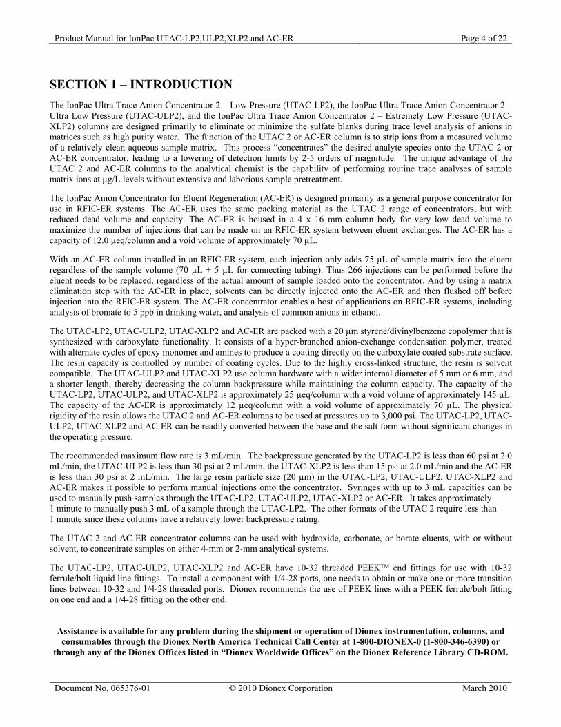
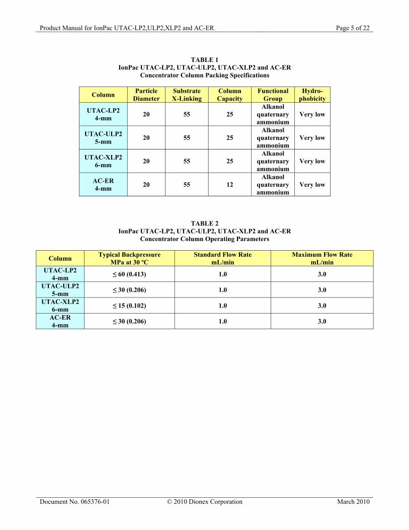
SECTION 1 – INTRODUCTION The IonPac Ultra Trace Anion Concentrator 2 – Low Pressure (UTAC-LP2), the IonPac Ultra Trace Anion Concentrator 2 – Ultra Low Pressure (UTAC-ULP2), and the IonPac Ultra Trace Anion Concentrator 2 – Extremely Low Pressure (UTAC-XLP2) columns are designed primarily to eliminate or minimize the sulfate blanks during trace level analysis of anions in matrices such as high purity water. The function of the UTAC 2 or AC-ER column is to strip ions from a measured volume of a relatively clean aqueous sample matrix. This process “concentrates” the desired analyte species onto the UTAC 2 or AC-ER concentrator, leading to a lowering of detection limits by 2-5 orders of magnitude. The unique advantage of the UTAC 2 and AC-ER columns to the analytical chemist is the capability of performing routine trace analyses of sample matrix ions at µg/L levels without extensive and laborious sample pretreatment. The IonPac Anion Concentrator for Eluent Regeneration (AC-ER) is designed primarily as a general purpose concentrator for use in RFIC-ER systems. The AC-ER uses the same packing material as the UTAC 2 range of concentrators, but with reduced dead volume and capacity. The AC-ER is housed in a 4 x 16 mm column body for very low dead volume to maximize the number of injections that can be made on an RFIC-ER system between eluent exchanges. The AC-ER has a capacity of 12.0 µeq/column and a void volume of approximately 70 µL. With an AC-ER column installed in an RFIC-ER system, each injection only adds 75 μL of sample matrix into the eluent regardless of the sample volume (70 µL + 5 µL for connecting tubing). Thus 266 injections can be performed before the eluent needs to be replaced, regardless of the actual amount of sample loaded onto the concentrator. And by using a matrix elimination step with the AC-ER in place, solvents can be directly injected onto the AC-ER and then flushed off before injection into the RFIC-ER system. The AC-ER concentrator enables a host of applications on RFIC-ER systems, including analysis of bromate to 5 ppb in drinking water, and analysis of common anions in ethanol. The UTAC-LP2, UTAC-ULP2, UTAC-XLP2 and AC-ER are packed with a 20 µm styrene/divinylbenzene copolymer that is synthesized with carboxylate functionality. It consists of a hyper-branched anion-exchange condensation polymer, treated with alternate cycles of epoxy monomer and amines to produce a coating directly on the carboxylate coated substrate surface. The resin capacity is controlled by number of coating cycles. Due to the highly cross-linked structure, the resin is solvent compatible. The UTAC-ULP2 and UTAC-XLP2 use column hardware with a wider internal diameter of 5 mm or 6 mm, and a shorter length, thereby decreasing the column backpressure while maintaining the column capacity. The capacity of the UTAC-LP2, UTAC-ULP2, and UTAC-XLP2 is approximately 25 µeq/column with a void volume of approximately 145 µL. The capacity of the AC-ER is approximately 12 µeq/column with a void volume of approximately 70 µL. The physical rigidity of the resin allows the UTAC 2 and AC-ER columns to be used at pressures up to 3,000 psi. The UTAC-LP2, UTAC-ULP2, UTAC-XLP2 and AC-ER can be readily converted between the base and the salt form without significant changes in the operating pressure. The recommended maximum flow rate is 3 mL/min. The backpressure generated by the UTAC-LP2 is less than 60 psi at 2.0 mL/min, the UTAC-ULP2 is less than 30 psi at 2 mL/min, the UTAC-XLP2 is less than 15 psi at 2.0 mL/min and the AC-ER is less than 30 psi at 2 mL/min. The large resin particle size (20 µm) in the UTAC-LP2, UTAC-ULP2, UTAC-XLP2 and AC-ER makes it possible to perform manual injections onto the concentrator. Syringes with up to 3 mL capacities can be used to manually push samples through the UTAC-LP2, UTAC-ULP2, UTAC-XLP2 or AC-ER. It takes approximately 1 minute to manually push 3 mL of a sample through the UTAC-LP2. The other formats of the UTAC 2 require less than 1 minute since these columns have a relatively lower backpressure rating. The UTAC 2 and AC-ER concentrator columns can be used with hydroxide, carbonate, or borate eluents, with or without solvent, to concentrate samples on either 4-mm or 2-mm analytical systems. The UTAC-LP2, UTAC-ULP2, UTAC-XLP2 and AC-ER have 10-32 threaded PEEK™ end fittings for use with 10-32 ferrule/bolt liquid line fittings. To install a component with 1/4-28 ports, one needs to obtain or make one or more transition lines between 10-32 and 1/4-28 threaded ports. Dionex recommends the use of PEEK lines with a PEEK ferrule/bolt fitting on one end and a 1/4-28 fitting on the other end.
Assistance is available for any problem during the shipment or operation of Dionex instrumentation, columns, and consumables through the Dionex North America Technical Call Center at 1-800-DIONEX-0 (1-800-346-6390) or
through any of the Dionex Offices listed in “Dionex Worldwide Offices” on the Dionex Reference Library CD-ROM.
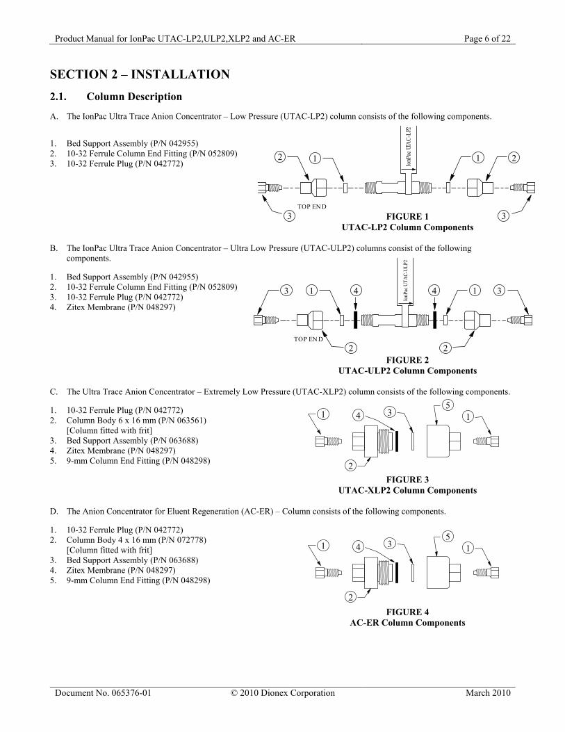
2.1. Column Description A. The IonPac Ultra Trace Anion Concentrator – Low Pressure (UTAC-LP2) column consists of the following components. 1. Bed Support Assembly (P/N 042955) 2. 10-32 Ferrule Column End Fitting (P/N 052809) 3. 10-32 Ferrule Plug (P/N 042772) FIGURE 1 UTAC-LP2 Column Components B. The IonPac Ultra Trace Anion Concentrator – Ultra Low Pressure (UTAC-ULP2) columns consist of the following
components. 1. Bed Support Assembly (P/N 042955) 2. 10-32 Ferrule Column End Fitting (P/N 052809) 3. 10-32 Ferrule Plug (P/N 042772) 4. Zitex Membrane (P/N 048297) FIGURE 2 UTAC-ULP2 Column Components C. The Ultra Trace Anion Concentrator – Extremely Low Pressure (UTAC-XLP2) column consists of the following components. 1. 10-32 Ferrule Plug (P/N 042772) 2. Column Body 6 x 16 mm (P/N 063561)
[Column fitted with frit] 3. Bed Support Assembly (P/N 063688) 4. Zitex Membrane (P/N 048297) 5. 9-mm Column End Fitting (P/N 048298) FIGURE 3 UTAC-XLP2 Column Components D. The Anion Concentrator for Eluent Regeneration (AC-ER) – Column consists of the following components. 1. 10-32 Ferrule Plug (P/N 042772) 2. Column Body 4 x 16 mm (P/N 072778)
[Column fitted with frit] 3. Bed Support Assembly (P/N 063688) 4. Zitex Membrane (P/N 048297) 5. 9-mm Column End Fitting (P/N 048298)
FIGURE 4 AC-ER Column Components
IonP
ac UT
AC-L
P2
12
3 3
1 2
TOP EN D
IonP
ac U
TAC-
ULP2
1 14 4
22
33
TOP EN D
Product Manual for IonPac UTAC-LP2,ULP2,XLP2 and AC-ER Page 7 of 22
SECTION 3 – UTAC AND AC-ER SETUP Figure 5 illustrates the recommended setup for the Ultra Trace Anion Concentrator or Anion Concentrator for Eluent Regeneration.
SamplePump
Waste
To Column
UTAC 2 or AC-ERConcentrator
P/N 053763Restrictor(1000 psi at 2mL/min.)
From PumporAuto-Sampler
FIGURE 5 Recommended setup for UTAC 2 or AC-ER
SECTION 4 – OPERATION
4.1. Sample Loading
CAUTION
Ensure that the sample pump has 1000 psi backpressure applied at 2 ml/min flow rate. This will ensure that the pump will operate reliably.
WARNING
To prevent overloading the UTAC-LP2, UTAC-ULP2, UTAC-XLP2, or AC-ER, and/or loss of sample analytes, determine the concentration linearity over the desired analytical concentration range. See Section 3.4.1, “Capacity Consideration of Concentrators.”
Sample loading can be performed manually with a < 3 mL syringe. It takes approximately 1 minute to manually inject 3 mL of sample through the UTAC-LP2. Alternately, one can use a separate positive displacement pump such as the Dionex AXP pump (P/N 063973) with a restrictor (P/N 053763) installed as shown in Figure 5. Pump flow rates of approximately 3 mL/min can be used while maintaining sample concentration to ensure good quantification. The single pumps require about 1000psi back pressure to work efficiently.
WARNING
The flow direction during the concentration step is critical. In order to ensure optimal system performance, it is recommended that concentration always be performed in a counter current direction to the eluent flow.
After the sample has been loaded onto the UTAC-LP2, UTAC-ULP2, or UTAC-XLP2 or AC-ER in the direction opposite to the eluent flow, it is then eluted with eluent onto the guard and analytical columns (see Figure 6, “Loading the UTAC-LP2, UTAC-ULP2, UTAC-XLP2 or AC-ER Column”). Loading the sample in the opposite direction to the eluent flow ensures that the analyte ions are concentrated on the bottom end of the concentrator column upon loading. Upon injection, the analyte ions are eluted off the concentrator column by the eluent in a tight plug and is injected onto the guard and analytical column for further analysis. In this configuration the concentrated ions do not undergo any chromatographic separation in the concentrator column.. When injected, all of the ions are rapidly eluted off of the UTAC 2 or AC-ER columns, and onto the guard and analytical columns. On the other hand, if the sample is loaded onto the UTAC-LP2, UTAC-ULP2, UTAC-XLP2 or AC-ER in the same flow direction as the eluent flow, the anions are concentrated at the head of the column rather than at the bottom. When injected, the anions begin chromatographic separation on the concentrator before reaching the guard and analytical columns. Therefore, the retention time of the analytes would be significantly longer than a standard loop injection. Normally the function of the concentrator is to strip the ions of interest from the sample matrix and not to act as an analytical column.
Product Manual for IonPac UTAC-LP2,ULP2,XLP2 and AC-ER Page 9 of 22
4.2. Reagent and Sample Handling The following sections focus on critical points that must be followed when using the UTAC-LP2, UTAC-ULP2, UTAC-XLP2 or AC-ER concentrator columns. Proper consideration of these points will enable the analyst to obtain accurate and reproducible results at trace analyte levels. 4.2.1. Water Quality All water used in the preparation of standards and eluents must be deionized water with a specific resistance of 18.2 megohm-cm. The quality of the dilution water must be determined by Ion Chromatography since even deionized water with a specific resistance of 18.2 megohm-cm may contain trace levels of the ions of interest. To do this, analyze the water in exactly the same manner as the sample. 4.2.2. Sample Collection and Storage
CAUTION
Never use plastic syringes with rubber pistons for any loading of trace ions. These materials cause non-reproducible results.
At trace analyte concentration levels (µg/L), chances of contamination during collection or storage are high. Every container and every procedural step constitutes a potential source of contamination. Polystyrene containers with leak-tight caps can be used to store 1 to 5 µg/L levels of inorganic and organic anions for up to 8 days. Recommended storage vessels are Corning tissue culture flasks. The following procedure should be used for storage of µg/L level samples.
A. Rinse the polystyrene container and cap twice with deionized water having a specific resistance of 18.2 megohm-cm. Fill the container until it overflows, cap it securely, and soak for 4 hours.
B. Empty the container and refill it with deionized water having a specific resistance of 18.2 megohm-cm. Cap the
container securely. It should remain filled at least 24 hours before sample collection.
C. Empty the container and rinse it twice with the sample to be collected. Fill the container with the sample until it overflows and then cap the container securely. Be sure that the sample line does not touch the container.
4.2.3. Standards It is good practice to run standards at the beginning, middle, and end of each day to ensure constant instrument response. Because external standard quantification is used, it is critical that standard solutions are correctly prepared.
A. 1,000 mg/L (1 mg/L = 1 ppm) stock standard solutions should be prepared by accurately weighing amounts of salts as described in the instrument manual. These solutions are stable over a period of several months.
B. 1 mg/L stock standard solutions may be prepared by diluting 1 mL of 1,000 mg/L stock standard to 1,000 mL in
a volumetric flask. These solutions should then be transferred to clean polystyrene containers. They may be stored for up to one month.
C. 1 µg/L working standard solutions may be prepared by diluting 1 mL of the 1 mg/L stock standard to 1,000 mL.
These working standards are stored in polystyrene containers. They are stable up to 8 days, but Dionex recommends daily preparation since standard response is critical in the analysis.
Product Manual for IonPac UTAC-LP2,ULP2,XLP2 and AC-ER Page 10 of 22
4.3. Concentrator Capacity As in all ion exchange systems, the resin has a finite capacity. It can strip a given amount of ions from water. When the capacity of the concentrator is exceeded, the stripping will not be quantitative. This condition is referred to as column overload. When estimating the capacity of a concentrator, one must remember that the column is used in a dynamic state where the liquid containing the analytes is flowing over the resin at a finite rate. This reduces the capacity somewhat since the analyte ions have less time to interact with the resin surface. Low concentrator column capacity creates the following practical implications.
A. Trace analysis of an analyte is difficult in the presence of µg/L concentrations of species which exhibit higher or similar affinities for the resin. If the dynamic column capacity is exceeded, high affinity ions will displace the analytes on the ion exchange sites and result in their elution to waste during the loading process.
B. Conversely, qualitative analysis of ions with higher affinities for the resin in the presence of high concentrations
of ions with low affinities is possible. Again, the key to successful analysis is that the ionic content of the high affinity ion to be quantitated may not exceed the effective column capacity.
C. Do not dilute samples to be concentrated in eluent because the eluent ions elute the ions of interest.
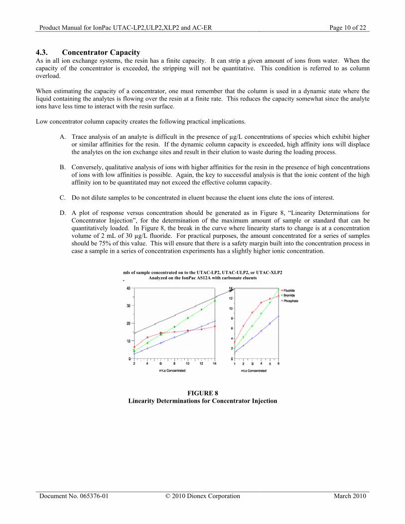
D. A plot of response versus concentration should be generated as in Figure 8, “Linearity Determinations for
Concentrator Injection”, for the determination of the maximum amount of sample or standard that can be quantitatively loaded. In Figure 8, the break in the curve where linearity starts to change is at a concentration volume of 2 mL of 30 µg/L fluoride. For practical purposes, the amount concentrated for a series of samples should be 75% of this value. This will ensure that there is a safety margin built into the concentration process in case a sample in a series of concentration experiments has a slightly higher ionic concentration.
mls of sample concentrated on to the UTAC-LP2, UTAC-ULP2, or UTAC-XLP2 Analyzed on the IonPac AS12A with carbonate eluents
FIGURE 8 Linearity Determinations for Concentrator Injection
Product Manual for IonPac UTAC-LP2,ULP2,XLP2 and AC-ER Page 11 of 22
4.3.1. Determination of the Concentrator Column Breakthrough Volume The breakthrough volume of an analyte ion is that volume of sample which causes an ion of interest to be eluted from, rather than retained or concentrated on, the concentrator column. The breakthrough volume for a concentrator column is usually defined as the volume of sample necessary to elute the most weakly retained ions of interest in the sample. The more strongly retained ions in the sample, such as sulfate, can elute the more weakly retained ions in the sample, such as fluoride. It is also possible for a high concentration of a weakly retained ion such as chloride to elute a more strongly retained ion present at low concentration. This can occur if one is attempting to concentrate trace ions in a concentrated matrix. The breakthrough is dependent upon several factors.
A. The volume of sample loaded. B. The rate at which the sample is loaded. C. The pH of the sample. D. The ionic strength of the sample. E. The amount and capacity of resin in the column.
The breakthrough volume is determined as follows.
A. Prepare 1 L of a solution that closely simulates the type of sample to be analyzed. For example, if the sample contains high levels of sulfate, the simulated sample should also contain sulfate. The sulfate ion will act as an eluent (E2).
B. Prepare a 1 mg/L standard of the first eluting ion of interest (e.g., F).
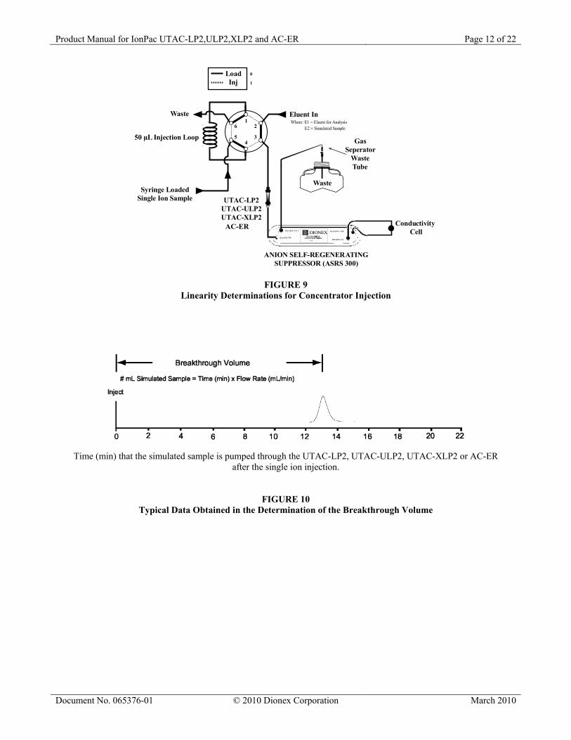
C. Set up the Ion Chromatograph, as shown in Figure 9, “Linearity Determinations for Concentrator Injection.”
D. Equilibrate the UTAC-LP2, UTAC-ULP2, UTAC-XLP2 or AC-ER with the eluent (E1) to be used in the
analysis. Set the flow rate necessary to achieve a stable baseline and wash the column in this manner for at least 10 minutes.
E. Switch to the simulated sample as an eluent (E2). Without delay, manually inject 50 µL of the 1 mg/L standard.
F. Record the resulting chromatogram and calculate the breakthrough volume, as shown in Figure 10, “Typical
Data Obtained in the Determination of the Breakthrough Volume.”
G. For practical purposes, the volume concentrated should be below 75% of the breakthrough volume.
Product Manual for IonPac UTAC-LP2,ULP2,XLP2 and AC-ER Page 13 of 22
SECTION 5 – ADDING AN ANION CONCENTRATOR FOR ELUENT REGENERATION (AC-ER)
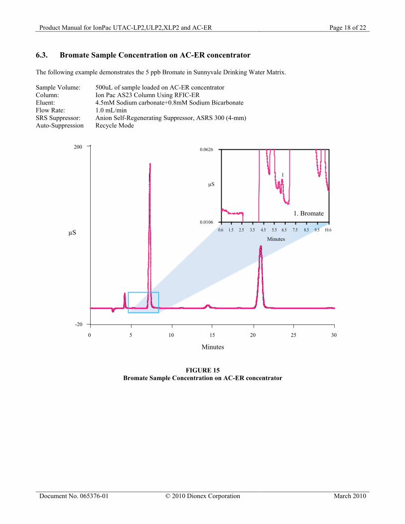
The AC-ER (4 x 16 mm) Anion Concentrator Column is a general purpose, low dead volume, extremely low pressure anion concentrator column designed for use in RFIC-ER systems. The AC-ER is housed in a 4 x 16 mm column body for very low dead volume to maximize the number of injections that can be made on an RFIC-ER system between eluent exchanges. The AC-ER has a capacity of 12.0 µeq/column, a void volume of approximately 70 µL, and is based on the same resin as the UTAC 2 concentrator columns. With an AC-ER column installed in an RFIC-ER system, each injection only adds 75 μL of sample matrix into the eluent regardless of the sample volume (70 µL + 5 µL for connecting tubing). Thus 266 injections can be performed before the eluent needs to be replaced, regardless of the actual amount of sample loaded onto the concentrator. And by using a matrix elimination step with the AC-ER in place, solvents can be directly injected onto the AC-ER and then flushed off before injection into the RFIC-ER system. The AC-ER concentrator brings a host of new applications within range of RFIC-ER systems, including analysis of bromate to 5 ppb in drinking water, and analysis of common anions in ethanol.
IMPORTANT: Do not inject ethanol or other solvents directly into an RFIC-ER system. Solvents should be loaded onto a concentrator such as the AC-ER, followed by a matrix elimination step to remove the solvent matrix prior to injection.
5.1. Installing the AC-ER Concentrator 1. Turn off the pump and suppressor. 2. Remove the old injection loop or concentrator column from the system injection valve. 3. Install two short (about 4 in. or 10 cm) lengths of 0.010” i.d. (black) tubing to the inlet and outlet ports of the AC-
ER concentrator column. 4. Connect the inlet of the AC-ER concentrator column to port 4 of the injection valve. Ensure the autosampler is
connected to port 3 of the injection valve. 5. Connect the outlet of the AC-ER concentrator column to port 1 of the injection valve. Ensure the waste line is
connected to port 2 of the injection valve.
5.2. Configuring Chromeleon 1. Ensure that data acquisition on all Timebase is turned off.
a. Open the Chromeleon Server Configuration. b. Open the Timebase that contains the system being upgraded. c. Double click the device to open the instrument properties dialog (ICS-1000/1100/1500/1600/2000/2100
System or ICS-3000 or ICS-5000 DC). d. For the ICS-1000/1100/1500/1600/2000/2100 select the Options tab. e. For the ICS-3000 or ICS-5000 DC select the Suppressors tab and double click the suppressor to which the
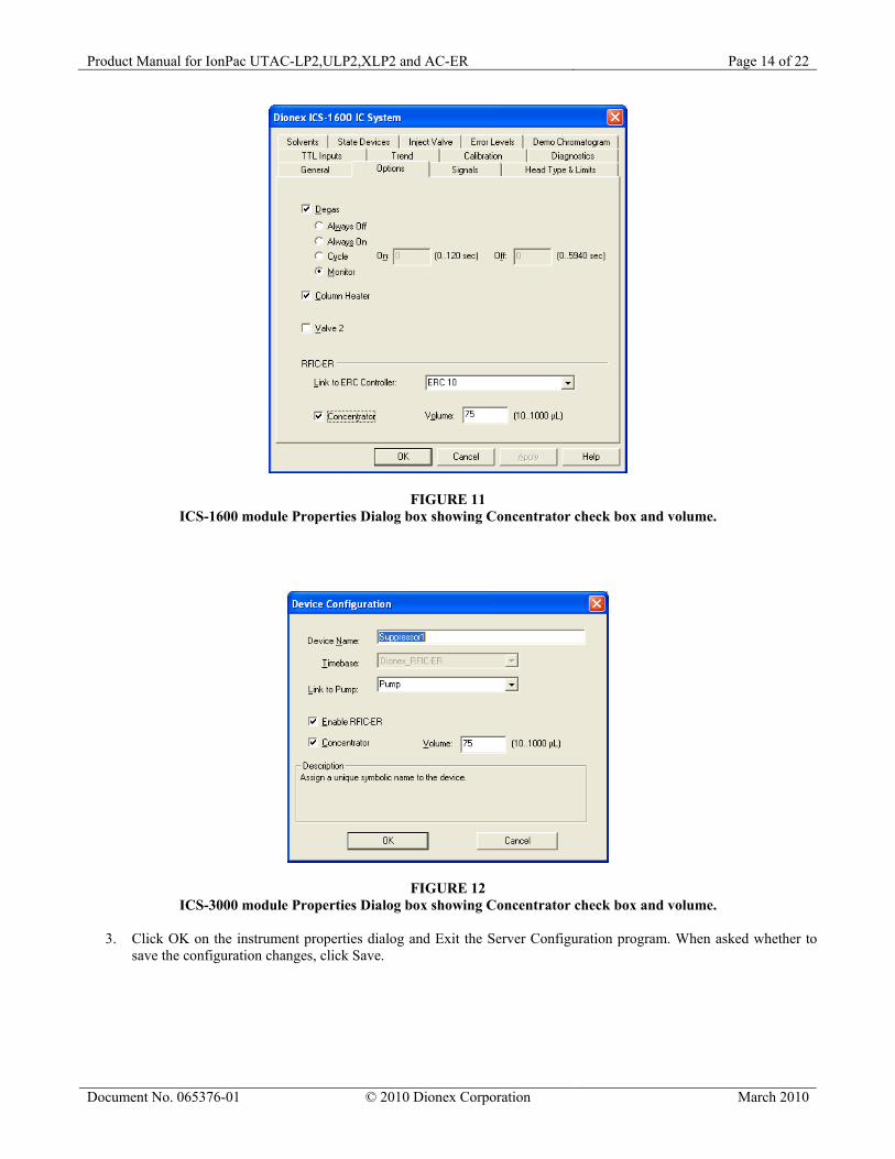
ERC-10 is linked. 2. Under the RFIC-ER section, check the Concentrator check box. For an AC-ER concentrator with associated tubing,
the Concentrator Volume should be set to 75 µL. If installing a concentrator other than an AC-ER, adjust the volume according to the dead volume specified in the manufacturer’s specifications. See Figure 1 for ICS-1000/1100/1500/1600/2000/2100 or Figure 2 for ICS-3000 or ICS-5000 DC.
Product Manual for IonPac UTAC-LP2,ULP2,XLP2 and AC-ER Page 15 of 22
5.3. AS Configuration
1. On the MODULE SETUP MENU, press 5 to go to the SYSTEM PARAMETERS screen. 2. Move the cursor to the SAMPLE MODE field and select CONCENTRATE. 3. See Section 3.8 of the AS Autosampler Operator’s Manual to set the correct Syringe Speed for the type of Sample
Syringe installed.
5.4. Operation Guidelines When operating an RFIC-ER system in Concentrator mode, Chromeleon will use the Concentrator Volume from the Server configuration to increment the Eluent counter and ER2 counter. The sequence table should be used to set the size of the sample to be loaded onto the concentrator. Thus, at 75 µL the Eluent Counter will allow 266 samples to be loaded before the eluent expires, regardless of the size of the sample actually loaded onto the concentrator.
Product Manual for IonPac UTAC-LP2,ULP2,XLP2 and AC-ER Page 16 of 22
SECTION 6 – EXAMPLE APPLICATIONS
6.1. Manual Concentration on UTAC-XLP2 Versus Direct Injection The following example demonstrates the advantages of sample concentration with low sensitivity detection versus direct injection with high sensitivity detection. Sample Loop Volume: See Chromatogram Column: Ion Pac AS22 Analytical Column Eluent: 4.5mM Na2CO3 + 1.4mN NaHCO3 Flow Rate: 1.2 ml/min Temperature: 30 °C SRS Suppressor: Anion Self-Regenerating Suppressor, ASRS 300 (4-mm) Auto Suppression Recycle Mode or MMS Suppressor: Anion Micro Membrane Suppressor, AMMS 300 (4-mm) MMS Regenerant: 50 mN H2SO4. or AES Suppressor: Anion Atlas Electrolytic Suppressor, AAES Peaks mg/L
Product Manual for IonPac UTAC-LP2,ULP2,XLP2 and AC-ER Page 17 of 22
6.2. Manual Concentration on UTAC-LP2 Versus Direct Injection The following example demonstrates the advantages of sample concentration with low sensitivity detection versus direct injection with high sensitivity detection. Sample Loop Volume: See Chromatogram Column: Ion Pac AS15 Analytical Column Eluent: 38mM NaOH Flow Rate: 1.2 mL/min SRS Suppressor: Anion Self-Regenerating Suppressor, ASRS 300 (4-mm) Auto-Suppression Recycle Mode or MMS Suppressor: Anion Micro Membrane Suppressor, AMMS 300 (4-mm) MMS Regenerant: 50mN H2SO4. or AES Suppressor: Anion Atlas Electrolytic Suppressor, AAES Peaks mg/L 1. Fluoride 0.1
Product Manual for IonPac UTAC-LP2,ULP2,XLP2 and AC-ER Page 19 of 22
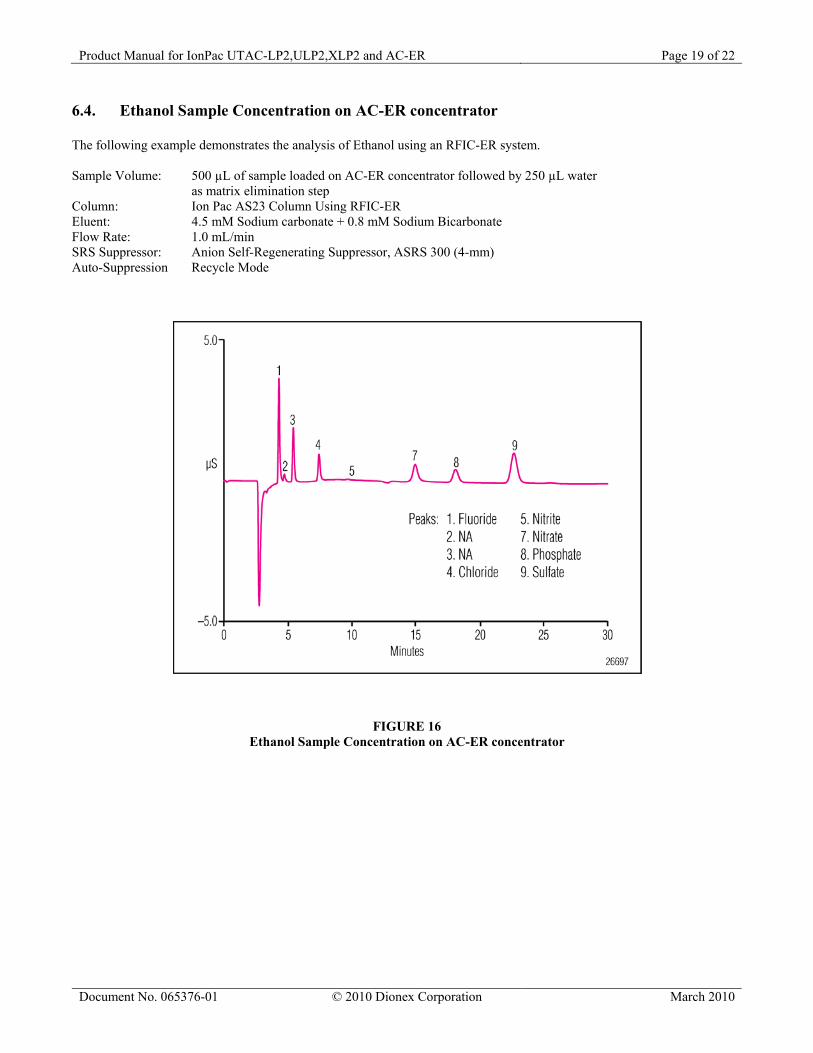
6.4. Ethanol Sample Concentration on AC-ER concentrator The following example demonstrates the analysis of Ethanol using an RFIC-ER system. Sample Volume: 500 µL of sample loaded on AC-ER concentrator followed by 250 µL water as matrix elimination step Column: Ion Pac AS23 Column Using RFIC-ER Eluent: 4.5 mM Sodium carbonate + 0.8 mM Sodium Bicarbonate Flow Rate: 1.0 mL/min SRS Suppressor: Anion Self-Regenerating Suppressor, ASRS 300 (4-mm) Auto-Suppression Recycle Mode
FIGURE 16 Ethanol Sample Concentration on AC-ER concentrator
Product Manual for IonPac UTAC-LP2,ULP2,XLP2 and AC-ER Page 20 of 22
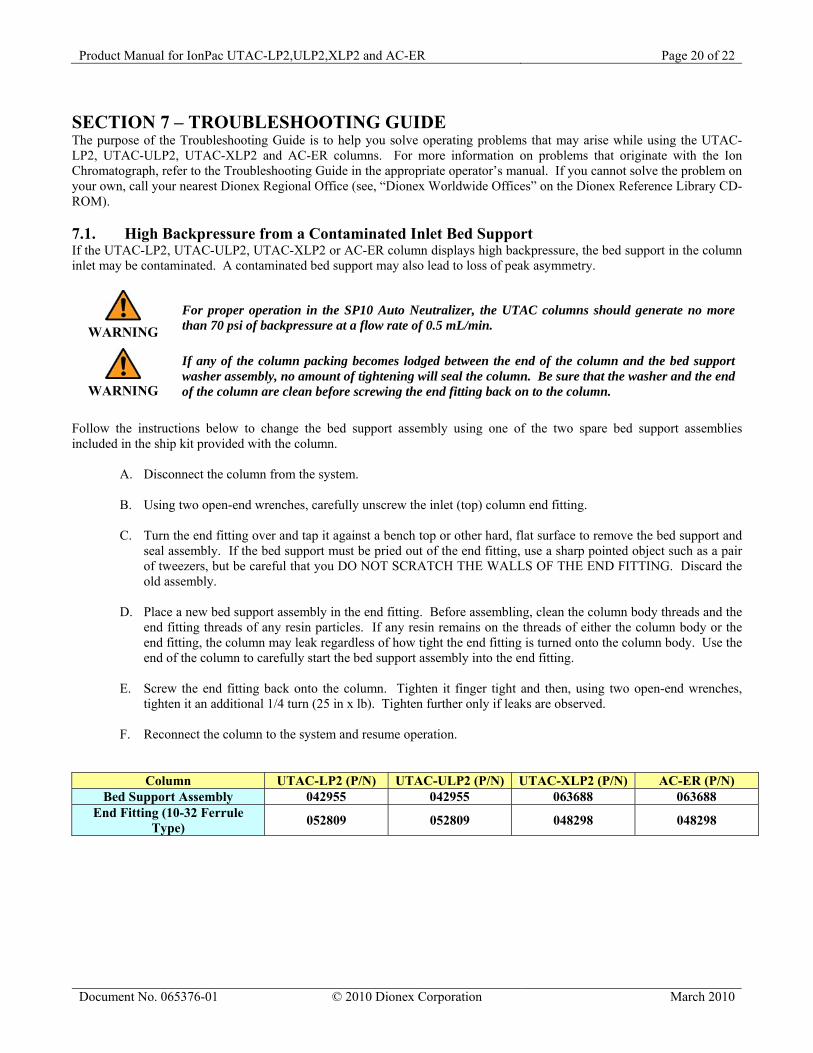
SECTION 7 – TROUBLESHOOTING GUIDE The purpose of the Troubleshooting Guide is to help you solve operating problems that may arise while using the UTAC-LP2, UTAC-ULP2, UTAC-XLP2 and AC-ER columns. For more information on problems that originate with the Ion Chromatograph, refer to the Troubleshooting Guide in the appropriate operator’s manual. If you cannot solve the problem on your own, call your nearest Dionex Regional Office (see, “Dionex Worldwide Offices” on the Dionex Reference Library CD-ROM). 7.1. High Backpressure from a Contaminated Inlet Bed Support If the UTAC-LP2, UTAC-ULP2, UTAC-XLP2 or AC-ER column displays high backpressure, the bed support in the column inlet may be contaminated. A contaminated bed support may also lead to loss of peak asymmetry.
WARNING
For proper operation in the SP10 Auto Neutralizer, the UTAC columns should generate no more than 70 psi of backpressure at a flow rate of 0.5 mL/min.
WARNING
If any of the column packing becomes lodged between the end of the column and the bed support washer assembly, no amount of tightening will seal the column. Be sure that the washer and the end of the column are clean before screwing the end fitting back on to the column.
Follow the instructions below to change the bed support assembly using one of the two spare bed support assemblies included in the ship kit provided with the column.
A. Disconnect the column from the system.
B. Using two open-end wrenches, carefully unscrew the inlet (top) column end fitting.
C. Turn the end fitting over and tap it against a bench top or other hard, flat surface to remove the bed support and seal assembly. If the bed support must be pried out of the end fitting, use a sharp pointed object such as a pair of tweezers, but be careful that you DO NOT SCRATCH THE WALLS OF THE END FITTING. Discard the old assembly.
D. Place a new bed support assembly in the end fitting. Before assembling, clean the column body threads and the
end fitting threads of any resin particles. If any resin remains on the threads of either the column body or the end fitting, the column may leak regardless of how tight the end fitting is turned onto the column body. Use the end of the column to carefully start the bed support assembly into the end fitting.
E. Screw the end fitting back onto the column. Tighten it finger tight and then, using two open-end wrenches,
tighten it an additional 1/4 turn (25 in x lb). Tighten further only if leaks are observed.
F. Reconnect the column to the system and resume operation.
Column UTAC-LP2 (P/N) UTAC-ULP2 (P/N) UTAC-XLP2 (P/N) AC-ER (P/N) Bed Support Assembly 042955 042955 063688 063688
End Fitting (10-32 Ferrule Type) 052809 052809 048298 048298
Product Manual for IonPac UTAC-LP2,ULP2,XLP2 and AC-ER Page 21 of 22
7.2. High Background, Noise, or Baseline Instability Normally, problems such as high background, noise, or baseline instability will not be attributable to the UTAC-LP2, UTAC-ULP2, UTAC-XLP2 or AC-ER column. These problems usually originate in the post-column detection chemistry. Before checking the UTAC-LP2, UTAC-ULP2, UTAC-XLP2 or AC-ER as the source of system background noise, consult the appropriate troubleshooting sections in the Ion Chromatograph Operator’s Manual, and the detector manual. If the source of the high background noise is isolated to the UTAC-LP2, UTAC-ULP2, UTAC-XLP2 or AC-ER then proceed with the following steps.
A. Be sure that the UTAC 2 or AC-ER column is not leaking. B. Be sure that the eluents are correctly formulated. C. If using an Anion Micro Membrane Suppressor 300 (AMMS® 300), be sure that the regenerant is formulated
correctly. D. Be sure that the eluents are made from chemicals with the recommended purity (see Section 3, “Operation”). E. Be sure that the deionized water used to prepare the reagents has a specific resistance of 18.2 megohm-cm.
7.3. Poor Peak Shape In some instances, poor peak shape in Ion Chromatography may be caused by a contaminated UTAC 2 or AC-ER column. To clean the UTAC 2 or AC-ER Column, see, “Column Cleanup of Polyvalent Anions and Base-Soluble Contaminants” in the Column Care Appendix.
Assistance is available for any problem during the shipment or operation of Dionex instrumentation, columns, and consumables through the Dionex North America Technical Call Center at 1-800-DIONEX-0 (1-800-346-6390) or
through any of the Dionex Offices listed in “Dionex Worldwide Offices” on the Dionex Reference Library CD-ROM.
A.1 Recommended Operating Pressures Operating a column above its recommended pressure limit can cause irreversible loss of column performance. The maximum recommended operating pressure for the IonPac Ultra Trace Anion Concentrator (UTAC 2) or Anion Concentrator for Eluent Regeneration (AC-ER) columns is 3,000 psi. A.2 Column Start-up The column is shipped with 20 mM NaOH as the storage solution. Flush the column for 30 minutes with eluent before attempting to concentrate sample. Pump the effluent directly to a waste container while washing the column. DO NOT pump this effluent through the guard column, analytical column, and/or the suppressor. A.3 Column Storage The UTAC 2 or AC-ER should be stored in the base form. Flush approximately 5 mL of 20 mM NaOH through the UTAC 2 or ACER column. A.4 Column Cleanup of Polyvalent Anions and Base-soluble Contaminants
A. Prepare a 500 mL solution of 0.5 M NaOH.
B. Disconnect the guard, analytical columns and the suppressor from the injection valve and the Conductivity Module. Disconnect the Gradient Mixer or Anion Trap Column from the Gradient Pump. Connect the UTAC 2 or AC-ER column directly to the Gradient Pump. Direct the effluent from the UTAC 2 or AC-ER directly to a waste container.
C. Set the flow rate to 1 mL/min.
D. Pump the 0.5 M NaOH solution through the column for 15-30 minutes.
E. Equilibrate the UTAC 2 or AC-ER with eluent for 15 minutes at 1 mL/min before resuming normal operation.
F. Reconnect the anion guard, analytical column and the suppressor between the injection valve and the
Conductivity Module. Reconnect the Gradient Mixer or Anion Trap Column between the Gradient Pump and the Injection Valve. Resume operation.
A.5 Column Cleanup of Organic/Anionic Contaminants
A. Prepare a 500 mL solution of 200 mM HCl/80% acetonitrile.
B. Disconnect the guard, analytical columns and the suppressor from the injection valve and the Conductivity Module. Disconnect the Gradient Mixer or Anion Trap column from the Gradient Pump. Connect the UTAC 2 or AC-ER column directly to the Gradient Pump. Direct the effluent from the UTAC 2 or AC-ER directly to a waste container.
C. Set the flow rate to 1 mL/min.
D. Pump the 200 mM HCl / 80% acetonitrile solution through the column for 15-30 minutes.
E. Equilibrate the UTAC 2 or AC-ER column with eluent for 15 minutes at 1 mL/min before resuming normal
operation.
F. Reconnect the Anion Guard, analytical column and the suppressor between the injection valve and the Conductivity Module. Reconnect the Gradient Mixer or Anion Trap Column between the Gradient Pump and the Injection Valve. Resume operation.