42
I Product Manual Applicable Model: CMA1325C-B-A Version: 1.0
| Date post: | 20-Mar-2018 |
| Category: |
Documents |
| Upload: | trinhkhanh |
| View: | 247 times |
| Download: | 5 times |

I
Product Manual
Applicable Model: CMA1325C-B-A
Version: 1.0
II
Copyright Statement
GD Han’s Yueming Laser Group Co., Ltd.
All rights reserved.
GD Han’s Yueming Laser Group Co., Ltd. (Han’s Yueming Laser hereafter) reserves the right to modify the products and product specifications described in this manual without advance notice.
Han’s Yueming Laser is not responsible to any direct, indirect, or consequential damage or liability caused by improper use of this manual or the product.
Han’s Yueming Laser owns the patent, copyright or any other intellectual property right of this product and the related software. No one shall duplicate, reproduce, process or use this product and its parts, unless authorized by Han’s Yueming Laser.
All the name referred in this manual only for identification, if belongs to other company’s registered trademark or copyright, proprietary rights of the name belongs to their respective holder.
III
Disclaimer and Responsibility Statement
Whole using the machine from our company, users are required to ensure integrity and independence of the product including but not limited to: mechanical, electrical, optical, control software and accessories. Unauthorized modification is strictly prohibited. It is a must to satisfy operating environment and operating specifications specified in the owner’s manual. For the followings:
Machine modified with no authorization (including but not limited to: add, remove, modify, unauthorized disassembly, replacing parts);
Use the machine in the environment failing to satisfy the operating requirements;
Operate disobeying the specifications of our company;
Unauthorized use the machine parts, accessories and auxiliaries on to other machine or in other places;
Viciously disassemble, destroy, decode hardware and software of the machine from our company
Our company shall not undertake any direct, indirect or joint responsibility. Our company reserves the rights to ascertain legal responsibility for the serious consequences or economic losses or reputation losses caused by what mentioned above.

IV
Foreword
Thanks for purchasing the laser engraving machine control system of our company.
Before operating, please read this manual carefully to ensure proper operation.
Please keep the manual properly for reference.
Since the configs are different, certain models do not have the functions listed in this manual. Please refer to the specific functions for details.
Due to the constantly tech update, the specification for reference only, subject to the real standard.
Tags in this book:
Alarm
Special Attention: User must follow and perform as the manual; otherwise, it could lead to errors or relatively serious problem.
Note
Note: User should comply with the attention and suggestion in this manual; it could bring much easier operation.
Warning
For a particular case there is no dedicated staff to guide the operation could lead to catastrophic happens

IV
Safety Precautions
Attention
Before using the machine, users are required to carefully read this manual and other operating requirements, strictly abide by the operating specifications. Professional are required for operating the machine.
Warning
The machine uses class 4 laser (strong laser radiation). The laser radiation may possibly cause the following accidents: emblaze the surrounded flammable materials; generate other radiations and toxic or hazardous gas by processed objects during laser processing; direct irradiation of laser radiation cause harm to human body. Therefore, firefighting devices are required in the operating place of the machine. Stacking flammable or explosive objects near the machine is strictly prohibited. Good ventilation is a must. Only the qualified personnel are authorized to approach the machine.
Note
The processed objects and discharged materials are required to satisfy requirements as per local laws and regulations.
Warning
Laser processing is with potential risks. Users should carefully make sure if the processed objects are suitable for laser processing. There is high voltage and potential risk in the laser machine. Unauthorized disassembly by unqualified personnel is prohibited. Reliable earthing is required for the machine and related other machine before power-on. During operating, removing any cover of the machine is strictly prohibited. During operating, the operators are required to observe working status of the machine all the time. In case of any abnormality, it is immediately to disconnect power supply and take active and corresponding measures. After power-on, special personnel are required for monitoring. Unauthorized leaving is strictly prohibited. It is a must to disconnect the power supply before leaving.
Warning
It is strictly prohibited to placing any unrelated all-reflective or diffusion reflective objects in the machine to prevent laser reflecting to human body or flammable materials
Attention
The environment for the machine should be dry, free of interference and influences from pollution, vibration, high voltage and strong magnet. The operating ambient temperature ranges 5-40 ℃, and the -85% (no dew); The machine should be far from electric appliances sensitive to electromagnetic interference; Operating voltage: AC220V, 50Hz. Power-on is strictly prohibited in case of unstable voltage of the power grid or unspecified voltage.
Attention
Chapter two of this manual is for Safety Rules. Please refer to the chapter more details concerning safe operation of the machine. Users are required to carefully read and abide by all the requirements of safety.
V
Content
Copyright Statement ............................................................................................................................... II
Disclaimer and Responsibility Statement ............................................................................................... III
Foreword ................................................................................................................................................ IV
Safety Precautions ...................................................................................................................................... IV
Chapter1. Product Introduction ............................................................................................................. 1
1.1 Overview ............................................................................................................................... 1
1.2 Product parameters and requirements ................................................................................ 1
1.3 Using environment ................................................................................................................ 1
1.4 Equipment composition ........................................................................................................ 2
1.4.1 Auxiliary equipment .............................................................................................................. 2
1.5 Software control system ....................................................................................................... 3
Chapter2. Safety Rules ........................................................................................................................... 4
2.1 Refer to safety standards ...................................................................................................... 4
2.2 Product safety ....................................................................................................................... 4
2.3 Safe equipment ..................................................................................................................... 4
2.4 Safety awareness .................................................................................................................. 4
2.5 Requirements for personnel ................................................................................................. 5
2.5.1 Definition of terms ................................................................................................................ 5
2.5.2 Qualifications ........................................................................................................................ 5
2.5.3 Responsibility ........................................................................................................................ 5
2.5.4 Personal protective devices .................................................................................................. 5
Chapter3. Equipment Installation and Commissioning ......................................................................... 6
3.1 Equipment installation .......................................................................................................... 6
3.1.1 Unpacking steps .................................................................................................................... 6
3.1.2 Out of box audit .................................................................................................................... 7
3.1.3 Preparation for installation ................................................................................................... 8

VI
3.1.4 Machine level adjustment .................................................................................................... 8
3.1.5 Installing ventilation tube ..................................................................................................... 9
3.1.6 Installing laser ..................................................................................................................... 10
3.1.7 Installing water cooling system ........................................................................................... 11
3.1.8 Installing air pump .............................................................................................................. 12
3.1.9 Installing external power .................................................................................................... 13
3.1.10 Equipment grounding ......................................................................................................... 13
3.1.11 Installing software and device drivers ................................................................................ 14
3.1.12 Installing other accessories ................................................................................................. 14
3.2 Instructions of machine button .......................................................................................... 14
3.2.1 Main power switch.............................................................................................................. 14
3.2.2 Emergent stop button ......................................................................................................... 15
3.2.3 Motion system power button ............................................................................................. 16
3.2.4 Laser system power button ................................................................................................ 16
3.2.5 USB&LAN interface ............................................................................................................. 16
3.3 Equipment debugging ......................................................................................................... 17
3.3.1 Switching sequence ............................................................................................................. 17
3.3.2 Movement debugging ......................................................................................................... 17
3.3.3 Laser debugging .................................................................................................................. 18
3.3.4 Processing commissioning .................................................................................................. 21
Chapter4. Care and Maintenance ........................................................................................................ 23
4.1 Mechanical maintenance .................................................................................................... 23
4.1.1 Guide rail, Lead screw ......................................................................................................... 23
4.1.2 Synchronous belt and synchronous pulley ......................................................................... 24
4.1.3 Fasten screws and coupling ................................................................................................ 24
4.2 Electrical inspection ............................................................................................................ 25
4.2.1 Limit switch ......................................................................................................................... 25
4.2.2 Stop button ......................................................................................................................... 25
VII
4.3 Light route and optics parts maintenance .......................................................................... 25
4.4 Auxiliary equipment maintenance ...................................................................................... 27
4.4.1 Cleaning the fan .................................................................................................................. 27
4.4.2 Water chiller maintenance ................................................................................................. 28
4.4.3 Worktable maintenance ..................................................................................................... 29
4.5 Maintenance cycle .............................................................................................................. 29
4.6 Runtime maintenance ......................................................................................................... 30
4.7 Maintenance of long-term shutdown ................................................................................. 30
Chapter5. Troubleshooting .................................................................................................................. 31
Chapter6. Transportation, Shipment and Storage ............................................................................... 32
6.1 Packaging ............................................................................................................................ 32
6.2 Transport and shipment method and precautions ............................................................. 32
6.3 Storage conditions, period and precautions ....................................................................... 32
6.4 Flat Machine Installation Diagram ...................................................................................... 33
Postscript ................................................................................................................................................... 34

1
Chapter1. Product Introduction
1.1 Overview
CMA1325C-BA non-metal laser cutting machine is a laser cutting machine designed by Guangdong Han's Yueming LaserGroup Co., Ltd. for laser cutting of non-metallic materials. Featuring high-speed, high-precision, high efficiency and cost effective, it is a high-tech product that integrates laser cutting, precision machinery and motion control technology. It is a high-precision, high performance and highly automated laser cutting machine and is widely used in advertising, die cutter, crafts and other processing industries.
CMA1325C-B-A laser cutting machine has the following features:
Use CO2 glass laser tube;
Use high rigidity thickened welding frame, and carry out vibration aging treatment to ensure that the machine is stable and reliable;
The beam structure is made of high-strength aluminum alloy, featuring light weight, high rigidity and smoother running compared with traditional steel beams;
Semi flying optical path design improves the consistency and quality of the beam in the entire work area;
Japan Shinano stepper motor and Taiwan precision linear guide rail offer high dynamic response for the machine;
Box exhaust system ensures clean working environment;
Support Bmp, plt, dst, ai and other file formats, easy to operate;
Support thick plate cutting, and maximum acrylic cutting thickness is 30mm.
1.2 Product parameters and requirements
Maximum size of cutting sheet 1300mm×2500mm
Maximum speed 18m/min
Positioning accuracy ±0.2mm/1000mm
Repeat positioning accuracy ±0.1mm/1000mm
Cooling mode Water cooling
Drawing format Bmp, plt, dst, ai
Work environment 5-40℃, RH ≤ 85%, non-condensing
Equipment power <4KW
Power requirement 220V/50Hz
1.3 Using environment Humidity: 5%~85%, non-condensing;

2
Temperature: 5 ℃-40 ℃;
Power supply: AC220V, 50Hz;
Ground: The resistance to ground should be less than 5Ω;
The environment for the equipment should be dry, smokeless, dust-free, pollution-free, and shouldn’t have vibration, strong current, strong magnetic field and other interferences.
Air pressure: 86-106kpa.
1.4 Equipment composition
CMA1325C-B-A laser cutting machine adopts modular design and consists of the frame, beams, cutting head, worktable, console and auxiliary equipment, as shown below:
Fig.1-1 CMA1325C-B-A Laser Cutting Machine (refer to real machine)
1.4.1 Auxiliary equipment In order to ensure the normal operation, the laser equipment also requires some auxiliary parts, such as fan
and chiller. Different models have different auxiliary parts, and the actual equipment shall prevail.
Air pump Fan Water chiller
Fig.1-2 Auxiliary equipment
3
1.5 Software control system
SmartCarve4 software is new PC platform software launched by Han's Yueming Laser Group Co., Ltd. and supports process control or data generation. The major functions are computer-aided design, computer intelligent control, graphics and image processing, support for multiple data types, a variety of laser machining processes, multi-layer setting and multi-language support, as described below:
Computer-aided design capabilities. SmartCarve4 software can achieve simple graphics rendering and editing, including solid lines, rectangles, polygons, arcs, ellipses, curves, texts, perforation and other element drawing and editing; supporting element node editing, allowing easy tuning of graphics; support graphics translation, rotation, mirroring, stretching, shearing, alignment, cloning, arrangement, filling, slope handling and other advanced editing features;
Support importing a variety of graphics data, including: plt, dxf, dst, dsb, ai, bmp, jpg, gif, out, oux, ymd, yln, cut, smc, etc.;
Simple graphics and image processing functions, including vector and bitmap translation, rotation, mirroring, stretching, shearing, arrangement, cloning and other major editing functions; support bitmap dot graphics processing and inverse color processing;
Support multiple languages: SmartCarve4 software fully supports Unicode, and supports languages of all countries theoretically. The standard format is internationally accepted Xml files, and the users can modify the languages. Currently the software is available in Chinese Simplified, Chinese Traditional and English, and the user can add/delete accordingly;
Support up to 256 processing layers, and the user can set the processing parameters and priority of different layers as needed.

4
Chapter2. Safety Rules This chapter mainly introduces safety warnings for protecting personnel and the machine, and makes an
introduction to signs used in the owner’s manual. The machine is already equipped with sufficient safety guarantee, yet it is still with certain risk. All the operators are required to carefully read through and well understand the safety rules.
2.1 Refer to safety standards
Laser processing equipment and operations shall be in accordance with both two national standards, which are GB7247-87 Radiation safety of laser products, equipment classification, requirements and user guide, and GB10320-88 electrical safety of laser equipment and facilities.
2.2 Product safety
The following conditions are required to be satisfied to ensure safe work:
Abide by operation manual and instruction signs;
Operators and maintenance personnel have received training held by machine manufacture;
In case of operation by couples of person at the same time, division of responsibility should be made and followed;
No admission to the working area for the unauthorized personnel;
Avoid any working method breaking the safety rules;
Timely eliminate all the failures possibly causing lower safety coefficient;
Abide by maintenance regulations of the machine.
2.3 Safe equipment
Safety machines are used for protecting personnel, and unauthorized disassembly, bridge-group or by-pass connection are strictly prohibited; in case of failure with the safety machine, professional are required for repair. If part replacement is needed, the product with same model, specification and from the same manufacture is required; otherwise, written consent from the manufacturer is required.
2.4 Safety awareness
The machine can be operated only by skilled personnel or under supervision of them. Improper use or operation may possibly be very dangerous and cause damage to the machine. Therefore, the followings are strictly prohibited:
Placing heavy objects or stepping on the working table of the machine;
Used for processing the materials unapproved by manufacturer;
Staying of unauthorized personnel in the dangerous area (It is the responsibility of operators to ensure keeping unauthorized personnel away from the working area.);
5
Block of using emergency stop button (Regular check is required to ensure a good condition for the emergency stop button.)
2.5 Requirements for personnel
After trail operation, maintenance personnel from the manufacturer may perform training on the operators.
It is the responsibility of machine owner to have operators trained at corresponding level.
We have prepared ready a series of training course for your option. Please make phone call to our Customer Training Center for details.
2.5.1 Definition of terms All the personnel using or operating the machine are called User in the manual;
Different requirements are for different users. Users are classified into the followings:
Owner
Owner means the authorized person or representative to sign contract with the manufacturer. With authorization, the owner has rights to sign the agreement with binding force of law;
Operator
Operator means the personnel trained for operating the machine. Training of the operator includes participation of training held by the manufacturer.
Maintenance personnel
Maintenance personnel mean the technicians having received formal training for machine and electric engineering. The maintenance personnel are responsible for daily maintenance of the machine, and repair at low level if needed. Training on the maintenance personnel contains participation training held by manufacturer.
2.5.2 Qualifications The operator is required to accept guidance and training of the owner, and the operator is responsible for
the safety of a third party in the working area; the personnel required for further training and guidance are required work or operate the machine under supervision of the operators.
2.5.3 Responsibility
It is a must to clarify the related responsibilities of each performance (operation, maintenance, parameter setting), and carry it out. Unclarified responsibilities will cause safety hidden risks.
Owner is required to provide operation manual for the operators and maintenance personnel, and ensure that they have read and understood the operation manual.
2.5.4 Personal protective devices When technology or measures fail to absolutely avoid risk of health, the owner is required to provide
personal protective devices for operator and maintenance personnel. For example,
Protective gloves;
Laser-proof goggle;
Light respirator
6
Chapter3. Equipment Installation and Commissioning
3.1 Equipment installation
3.1.1 Unpacking steps
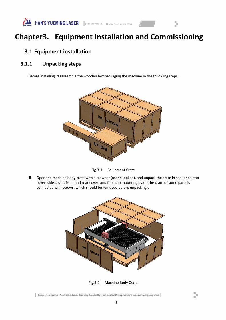
Before installing, disassemble the wooden box packaging the machine in the following steps:
Fig.3-1 Equipment Crate
Open the machine body crate with a crowbar (user supplied), and unpack the crate in sequence: top cover, side cover, front and rear cover, and foot cup mounting plate (the crate of some parts is connected with screws, which should be removed before unpacking).
Fig.3-2 Machine Body Crate

7
Fork the machine from the substrate with a forklift and transport to the destination, and unscrew the foot cup.
Then open the accessory crate, laser tube crate and laser crate.
Accessory Crate
Laser Tube Crate
3.1.2 Out of box audit After unpacking, examine the equipment and accessories to ensure that the product has no accident during
transport. Check the following items:
1. Equipment model audit
Please confirm if the model is the equipment you ordered.
Equipment appearance
Please check if the equipment appearance has scratches, breakage, deformation, corrosion and other defects.
2. Equipment interior audit
Open the beam organ cover, and check if the equipment has parts and thread falling off or internal damage.
8
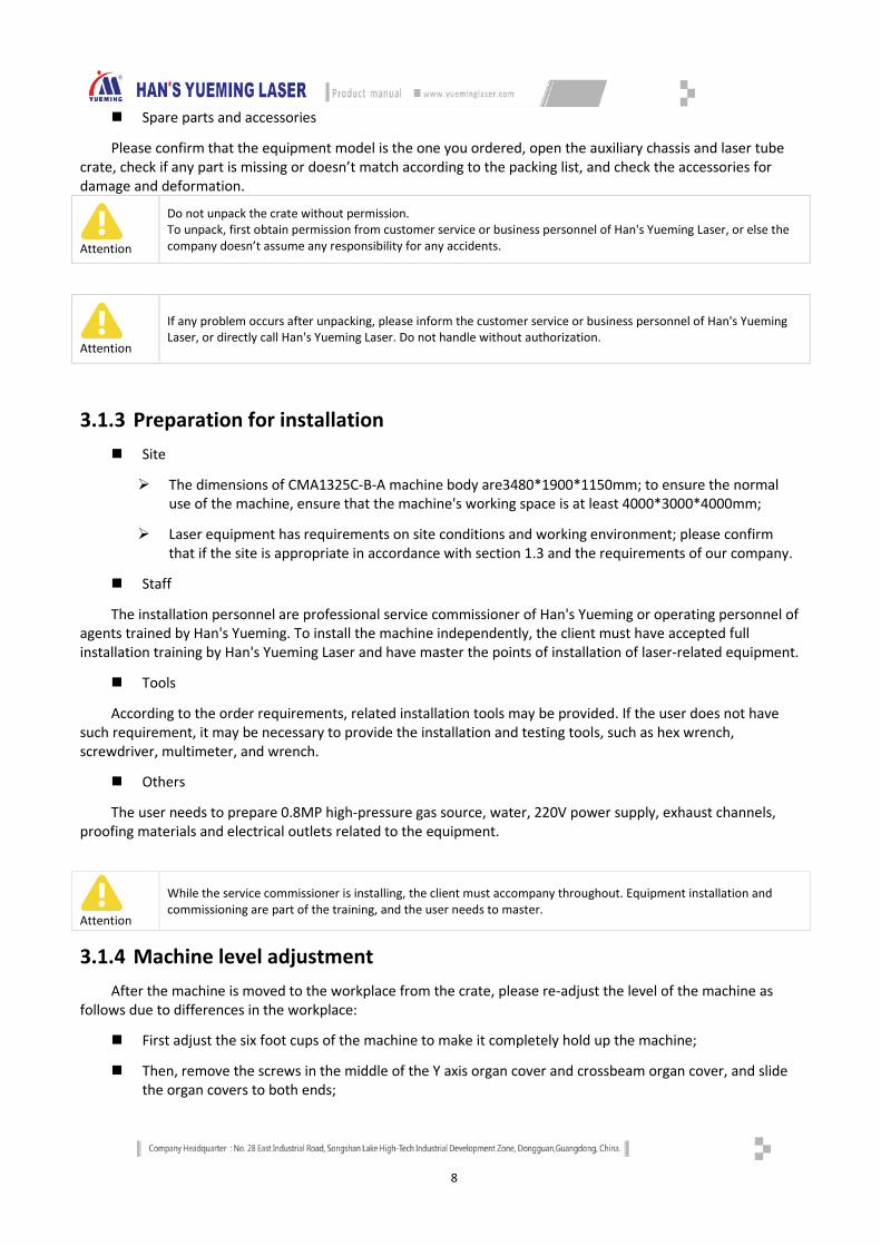
Spare parts and accessories
Please confirm that the equipment model is the one you ordered, open the auxiliary chassis and laser tube crate, check if any part is missing or doesn’t match according to the packing list, and check the accessories for damage and deformation.
Attention
Do not unpack the crate without permission. To unpack, first obtain permission from customer service or business personnel of Han's Yueming Laser, or else the company doesn’t assume any responsibility for any accidents.
Attention
If any problem occurs after unpacking, please inform the customer service or business personnel of Han's Yueming Laser, or directly call Han's Yueming Laser. Do not handle without authorization.
3.1.3 Preparation for installation Site
The dimensions of CMA1325C-B-A machine body are3480*1900*1150mm; to ensure the normal use of the machine, ensure that the machine's working space is at least 4000*3000*4000mm;
Laser equipment has requirements on site conditions and working environment; please confirm that if the site is appropriate in accordance with section 1.3 and the requirements of our company.
Staff
The installation personnel are professional service commissioner of Han's Yueming or operating personnel of agents trained by Han's Yueming. To install the machine independently, the client must have accepted full installation training by Han's Yueming Laser and have master the points of installation of laser-related equipment.
Tools
According to the order requirements, related installation tools may be provided. If the user does not have such requirement, it may be necessary to provide the installation and testing tools, such as hex wrench, screwdriver, multimeter, and wrench.
Others
The user needs to prepare 0.8MP high-pressure gas source, water, 220V power supply, exhaust channels, proofing materials and electrical outlets related to the equipment.
Attention
While the service commissioner is installing, the client must accompany throughout. Equipment installation and commissioning are part of the training, and the user needs to master.
3.1.4 Machine level adjustment After the machine is moved to the workplace from the crate, please re-adjust the level of the machine as
follows due to differences in the workplace:
First adjust the six foot cups of the machine to make it completely hold up the machine;
Then, remove the screws in the middle of the Y axis organ cover and crossbeam organ cover, and slide the organ covers to both ends;
9
Then, place the level meter on the rails of the machine, observe the offset direction of bubble in the level meter; first place the level meter on the rails of the beam; if bubble shifts left, the left side of the machine is higher than the right side; adjust the machine level by reducing the height of left foot cup of the machine or increasing the height of the right foot cup; when the bubble is centered in the level meter, the level of the machine front has been adjusted properly;
Then, adjust the level of the rear, left and right side successively in the same way. After adjusting the level of the four positions, the machine level has been adjusted properly, and next installation can proceed.
Attention
The machine level adjustment is required. If the machine level is quite different, it will affect the subsequent use of the machine.
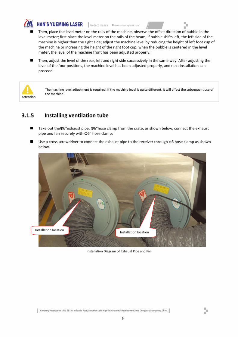
3.1.5 Installing ventilation tube
Take out theΦ6″exhaust pipe, Φ6″hose clamp from the crate; as shown below, connect the exhaust pipe and fan securely with Φ6" hose clamp;
Use a cross screwdriver to connect the exhaust pipe to the receiver through φ6 hose clamp as shown below.
Installation Diagram of Exhaust Pipe and Fan
Installation location
Installation location

10
Installation Diagram of Exhaust Pipe and Receiver
3.1.6 Installing laser
First, move the beam to the rearmost of the machine, and remove the rear shield of the beam;
Then, unscrew the screws from the top cover of the support base with a hex wrench;
Take out the laser tube from the box and place the laser in the support base of the laser tube;
Use a hex wrench to tighten the screws to the top cover of the support base, and fix the laser tube to the support base;
Adjust the position of the laser tube support base, and target the laser tube outlet at the first reflector;
Install earth wire, HV lines, inlet pipe and outlet pipe of the laser tube in sequence, and fix the lines with adhesive tape;
Adjust the optical path concentricity of the laser tube and the reflector by adjusting the support base of the laser tube and the nuts of the support base;
After adjusting the concentricity, fix the screws of the support base, and install the rear shield of the beam.
Installation location
Installation location
Install ground wire
Water inlet
Water outlet
Install HV wire (remove the cover before installing)
11
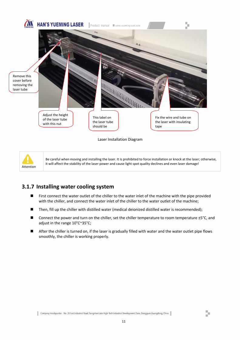
Laser Installation Diagram
Attention
Be careful when moving and installing the laser. It is prohibited to force installation or knock at the laser; otherwise, it will affect the stability of the laser power and cause light spot quality declines and even laser damage!
3.1.7 Installing water cooling system First connect the water outlet of the chiller to the water inlet of the machine with the pipe provided
with the chiller, and connect the water inlet of the chiller to the water outlet of the machine;
Then, fill up the chiller with distilled water (medical deionized distilled water is recommended);
Connect the power and turn on the chiller, set the chiller temperature to room temperature ±5°C, and adjust in the range 10°C~35°C;
After the chiller is turned on, if the laser is gradually filled with water and the water outlet pipe flows smoothly, the chiller is working properly.
Remove this cover before removing the laser tube
Adjust the height of the laser tube with this nut
This label on the laser tube should be
Fix the wire and tube on the laser with insulating tape
12
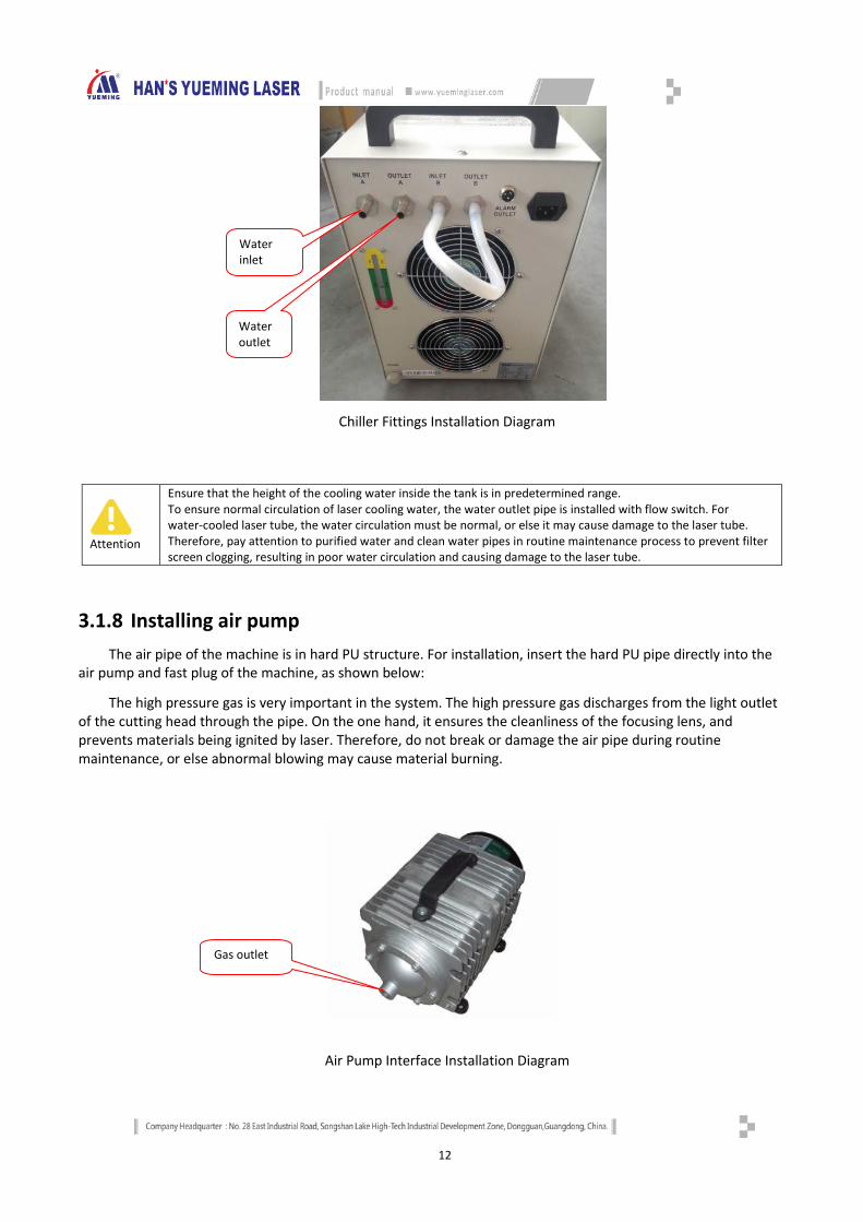
Chiller Fittings Installation Diagram
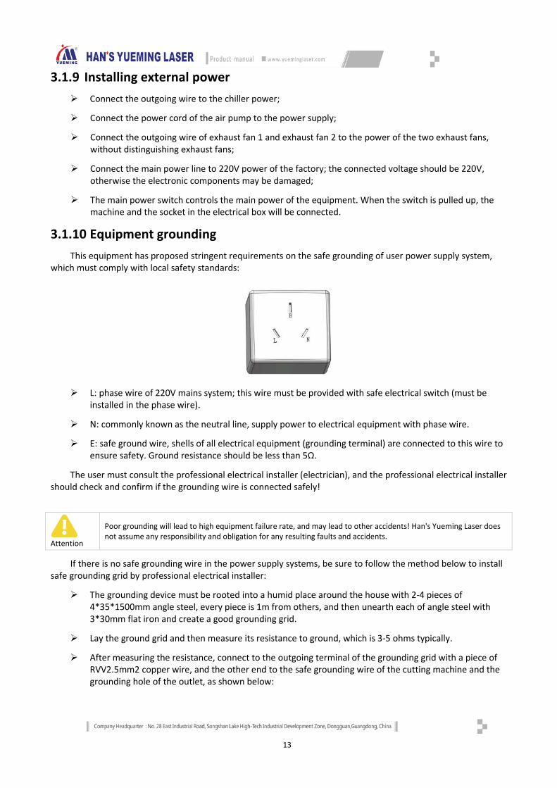
3.1.8 Installing air pump The air pipe of the machine is in hard PU structure. For installation, insert the hard PU pipe directly into the
air pump and fast plug of the machine, as shown below:
The high pressure gas is very important in the system. The high pressure gas discharges from the light outlet of the cutting head through the pipe. On the one hand, it ensures the cleanliness of the focusing lens, and prevents materials being ignited by laser. Therefore, do not break or damage the air pipe during routine maintenance, or else abnormal blowing may cause material burning.
Air Pump Interface Installation Diagram
Attention
Ensure that the height of the cooling water inside the tank is in predetermined range. To ensure normal circulation of laser cooling water, the water outlet pipe is installed with flow switch. For water-cooled laser tube, the water circulation must be normal, or else it may cause damage to the laser tube. Therefore, pay attention to purified water and clean water pipes in routine maintenance process to prevent filter screen clogging, resulting in poor water circulation and causing damage to the laser tube.
Water inlet
Water outlet
Gas outlet
13
3.1.9 Installing external power Connect the outgoing wire to the chiller power;
Connect the power cord of the air pump to the power supply;
Connect the outgoing wire of exhaust fan 1 and exhaust fan 2 to the power of the two exhaust fans, without distinguishing exhaust fans;
Connect the main power line to 220V power of the factory; the connected voltage should be 220V, otherwise the electronic components may be damaged;
The main power switch controls the main power of the equipment. When the switch is pulled up, the machine and the socket in the electrical box will be connected.
3.1.10 Equipment grounding This equipment has proposed stringent requirements on the safe grounding of user power supply system,
which must comply with local safety standards:
L: phase wire of 220V mains system; this wire must be provided with safe electrical switch (must be installed in the phase wire).
N: commonly known as the neutral line, supply power to electrical equipment with phase wire.
E: safe ground wire, shells of all electrical equipment (grounding terminal) are connected to this wire to ensure safety. Ground resistance should be less than 5Ω.
The user must consult the professional electrical installer (electrician), and the professional electrical installer should check and confirm if the grounding wire is connected safely!
Attention
Poor grounding will lead to high equipment failure rate, and may lead to other accidents! Han's Yueming Laser does not assume any responsibility and obligation for any resulting faults and accidents.
If there is no safe grounding wire in the power supply systems, be sure to follow the method below to install safe grounding grid by professional electrical installer:
The grounding device must be rooted into a humid place around the house with 2-4 pieces of 4*35*1500mm angle steel, every piece is 1m from others, and then unearth each of angle steel with 3*30mm flat iron and create a good grounding grid.
Lay the ground grid and then measure its resistance to ground, which is 3-5 ohms typically.
After measuring the resistance, connect to the outgoing terminal of the grounding grid with a piece of RVV2.5mm2 copper wire, and the other end to the safe grounding wire of the cutting machine and the grounding hole of the outlet, as shown below:

14
Equipment Grounding Diagram
3.1.11 Installing software and device drivers The equipment is equipped with different control boards according to customer needs. The drivers for
the main board are provided on the CD. The drivers have been installed before the machine is shipped, and reaches the requirements. For details of installation method, please refer to Main Board Control System Operating Manual.
PC software uses SmartCarve version. On the software installation and use, please refer to "Han's Yueming SmartCarve Software System Operating Manual".
Attention
The user shall take good care of the CD and software dongle. If lost, contact Han's Yueming to purchase. Reinstalling software may lead to loss of system parameters. Please back up the parameters before reinstalling
the software or system. The user should protect the safety of computer environment. Do not insert USB disk without permission, to
prevent virus. For common computer hardware and software failures, the user should have basic processing capabilities.
The user shall not install other software on the computer or use the computer for other purposes, or else the company is not responsible for the consequences.
3.1.12 Installing other accessories Some models may come with other accessories (such as foot switch), which need to be installed by service
commissioner of Han's Yueming Laser. In addition, the user needs to install the scanner and printer independently.
3.2 Instructions of machine button
3.2.1 Main power switch
Main power switch controls the master power supply of the equipment. It is located on the right side of the front shield of the frame, as shown below:
1m 1m 1m
3*30FLAT STEEL
4*35*1500mm ANGLE
STEEL GROUND
15
Main power switch
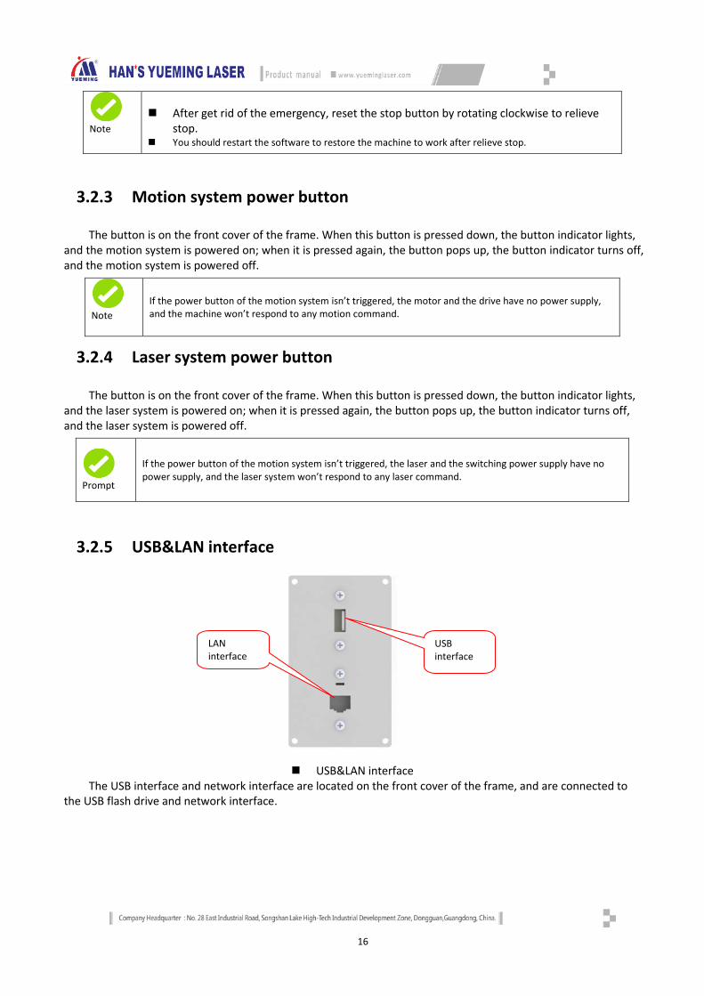
3.2.2 Emergent stop button
This button is mounted on the right side of the mounting plate of the control cabinet. Press any stop button to stopping when the emergency appears. All the dynamic power supply of machine will be switched off after you press the stop button, the machine stay at “stop” status.
Emergent stop button
Attention
After press the stop button, the system will switch off all the dynamic power supply (e.g. machine power supply and laser power supply), controlled power supply is still electrifying. Necessarily, if you want to switch off the power supply of the whole machine, you should turn off the switch of total power supply even pull out the electric cable of total power supply.
You can loosen the stop button and continue to operating only when the emergency has been removed and all the flaws have been rectified or the breakdown has been restored.
16
3.2.3 Motion system power button
The button is on the front cover of the frame. When this button is pressed down, the button indicator lights, and the motion system is powered on; when it is pressed again, the button pops up, the button indicator turns off, and the motion system is powered off.
3.2.4 Laser system power button
The button is on the front cover of the frame. When this button is pressed down, the button indicator lights, and the laser system is powered on; when it is pressed again, the button pops up, the button indicator turns off, and the laser system is powered off.
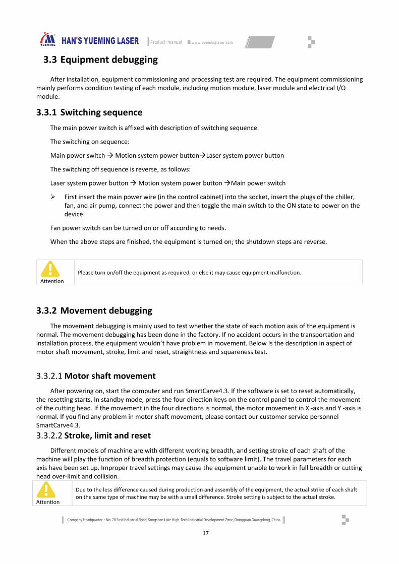
3.2.5 USB&LAN interface
USB&LAN interface The USB interface and network interface are located on the front cover of the frame, and are connected to
the USB flash drive and network interface.
Note
After get rid of the emergency, reset the stop button by rotating clockwise to relieve stop.
You should restart the software to restore the machine to work after relieve stop.
Note
If the power button of the motion system isn’t triggered, the motor and the drive have no power supply, and the machine won’t respond to any motion command.
Prompt
If the power button of the motion system isn’t triggered, the laser and the switching power supply have no power supply, and the laser system won’t respond to any laser command.
USB interface
LAN interface
17
3.3 Equipment debugging
After installation, equipment commissioning and processing test are required. The equipment commissioning mainly performs condition testing of each module, including motion module, laser module and electrical I/O module.
3.3.1 Switching sequence The main power switch is affixed with description of switching sequence.
The switching on sequence:
Main power switch Motion system power buttonLaser system power button
The switching off sequence is reverse, as follows:
Laser system power button Motion system power button Main power switch
First insert the main power wire (in the control cabinet) into the socket, insert the plugs of the chiller, fan, and air pump, connect the power and then toggle the main switch to the ON state to power on the device.
Fan power switch can be turned on or off according to needs.
When the above steps are finished, the equipment is turned on; the shutdown steps are reverse.
Attention
Please turn on/off the equipment as required, or else it may cause equipment malfunction.
3.3.2 Movement debugging The movement debugging is mainly used to test whether the state of each motion axis of the equipment is
normal. The movement debugging has been done in the factory. If no accident occurs in the transportation and installation process, the equipment wouldn’t have problem in movement. Below is the description in aspect of motor shaft movement, stroke, limit and reset, straightness and squareness test.
3.3.2.1 Motor shaft movement
After powering on, start the computer and run SmartCarve4.3. If the software is set to reset automatically, the resetting starts. In standby mode, press the four direction keys on the control panel to control the movement of the cutting head. If the movement in the four directions is normal, the motor movement in X -axis and Y -axis is normal. If you find any problem in motor shaft movement, please contact our customer service personnel SmartCarve4.3. 3.3.2.2 Stroke, limit and reset
Different models of machine are with different working breadth, and setting stroke of each shaft of the machine will play the function of breadth protection (equals to software limit). The travel parameters for each axis have been set up. Improper travel settings may cause the equipment unable to work in full breadth or cutting head over-limit and collision.
Attention
Due to the less difference caused during production and assembly of the equipment, the actual strike of each shaft on the same type of machine may be with a small difference. Stroke setting is subject to the actual stroke.

18
Limit switch is the hardware sensor equipped on limit position of the two ends of each shaft. After detecting limit triggering signal, the movement shaft will perform emergency stop to avoid “overreaching”. Minimum one limit switch is needed for each shaft to indicate limit position of the current shaft. The installation position of limit switch may differ due to different types of machine, so the triggering signal. Therefore, configuration is needed.
Zero point of the machine is a referential point of a certain hardware fixed in processing breadth. Generally, after power-on, “reset” is needed for the machine to create coordinate of lathe.
Attention
At ex-factory, configuration of parameters for stroke, limit and reset has been already performed. Unauthorized change of parameters by user before making clear its meaning is prohibited. Otherwise, failure of the equipment may possibly be caused.
3.3.2.3 Straightness and perpendicularity Before starting formal processing, testing of movement straightness of each movement shaft and
perpendicularity of X-axis and Y-axis are needed. The straightness ensures movement accuracy and stability of movement for this shaft. The testing shaft can be controlled to move along a straight line. If the straight line is measure unstraight, it means twittering exists during movement of the shaft, and a solution is required. Reasons for straightness of single shaft frequently lie in transmission of the motor or mechanical movement and machine vibration.
Movement coordinate system of the machine is a rectangular Cartesian coordinate system. Theoretically, X-axis and Y-axis should ensure be in absolute uprightness to ensure processing accuracy. If case of large tolerance for the straightness, distortion of the processed figure will be caused. Method of measuring the straightness is to have the control equipment go a rectangle frame on the surface of processing, and measure if the length of four sides and diagonal are the same. Method of adjusting perpendicularity is to make adjustment of assembly of X-axis and Y-axis movement mechanism.
Attention
Debugging of straightness of perpendicularity of each shaft has been already performed at ex-factory of the equipment. In case of problems found by users, please timely contact our customer service personnel for a solution. Unauthorized disassembly of the machine is prohibited.
3.3.3 Laser debugging Laser debugging contains two aspects: light emitting test and light route adjustment. The followings are the
details for them:
3.3.3.1 Light emitting test
After normal power up, press the laser power switch on the right side cover, and then set the light emitting energy and time directly on the control panel, and test if the laser emitting function is normal. If there is no laser emitting from the spot spray laser tube, it means that there is problems with the laser emitting, and check is required. In case of laser emitting found from the laser tube, but no laser emitting from the cutting head, it means improper position of the light route, and adjustment of light route is needed.
If there is no laser emitting, first check the setting of laser parameters. Improper laser parameters may cause equipment malfunction or laser power cannot be adjusted. If the laser parameters are determined correct and there is no emitting still, you need to check the hardware problem.
The control panel of some types of machine is equipped with ammeter. With the ammeter, you can check if the power is normal.
19
Tips
3.3.3.2 Light route adjustment
Due to vibration during transportation, aberrancy of light route may possibly be caused. At this time, light route correction is needed.
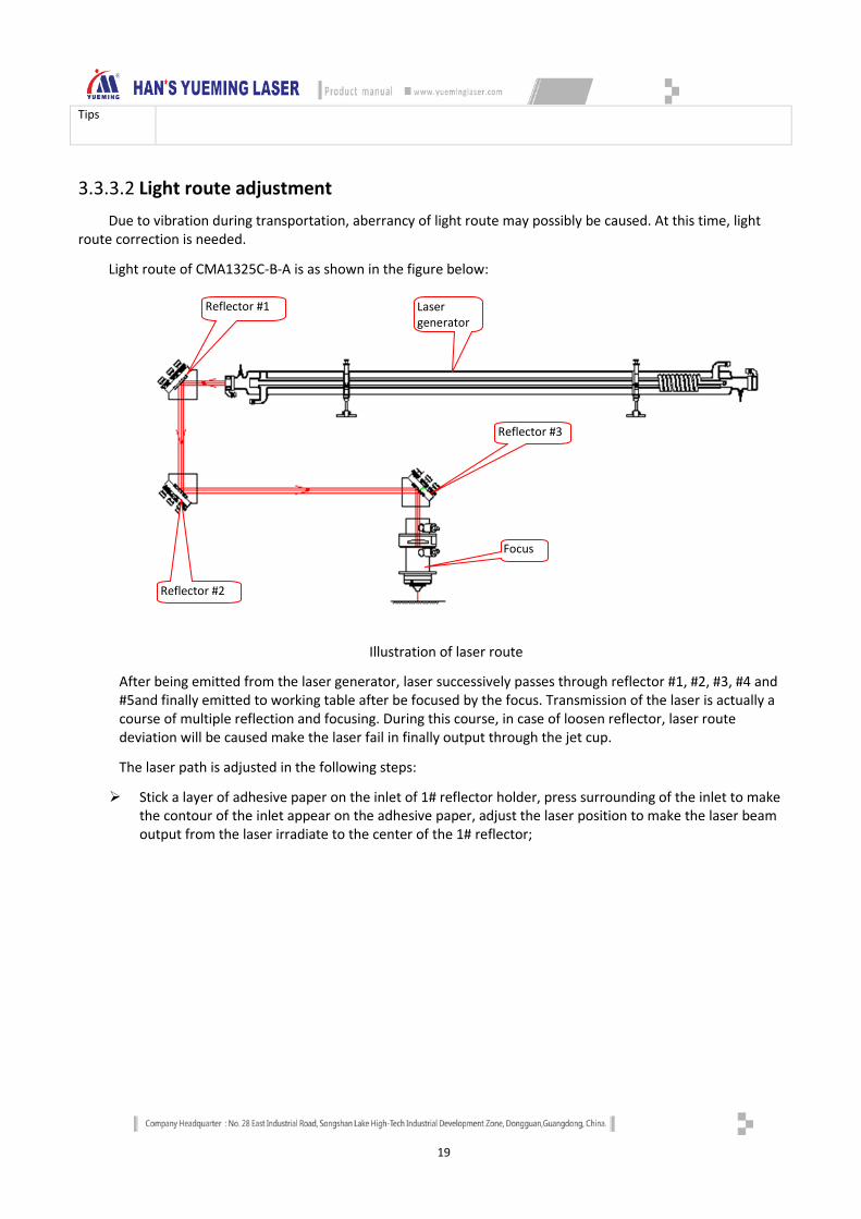
Light route of CMA1325C-B-A is as shown in the figure below:
Illustration of laser route
After being emitted from the laser generator, laser successively passes through reflector #1, #2, #3, #4 and #5and finally emitted to working table after be focused by the focus. Transmission of the laser is actually a course of multiple reflection and focusing. During this course, in case of loosen reflector, laser route deviation will be caused make the laser fail in finally output through the jet cup.
The laser path is adjusted in the following steps:
Stick a layer of adhesive paper on the inlet of 1# reflector holder, press surrounding of the inlet to make the contour of the inlet appear on the adhesive paper, adjust the laser position to make the laser beam output from the laser irradiate to the center of the 1# reflector;
第三反射镜
Laser generator
Reflector #2
Focus
Reflector #1
Reflector #3
20
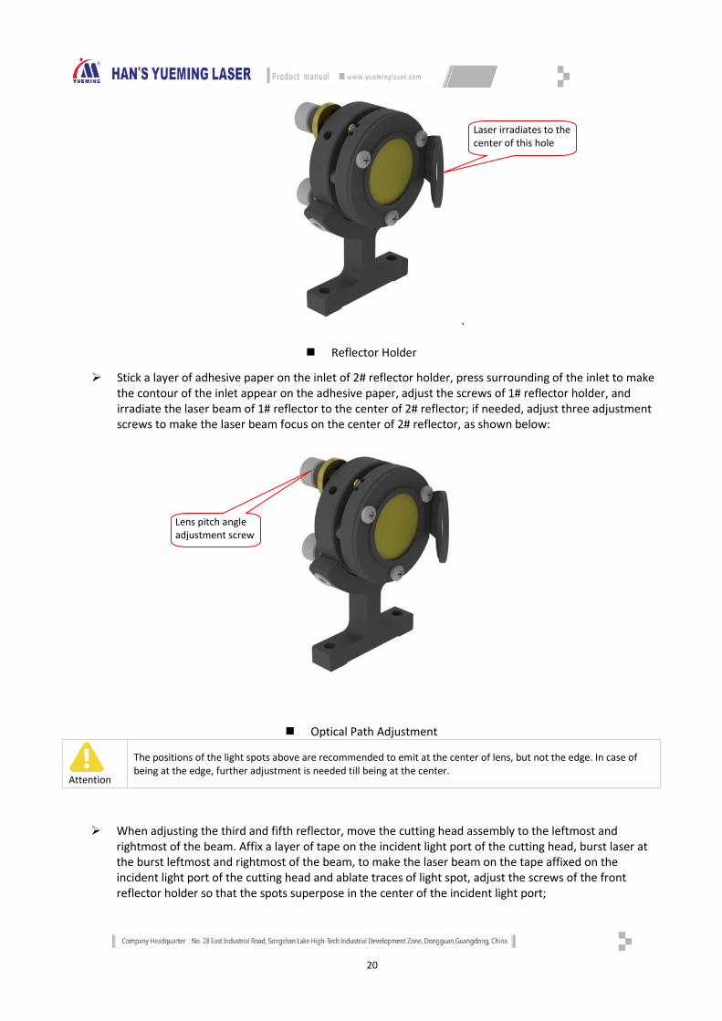
`
Reflector Holder
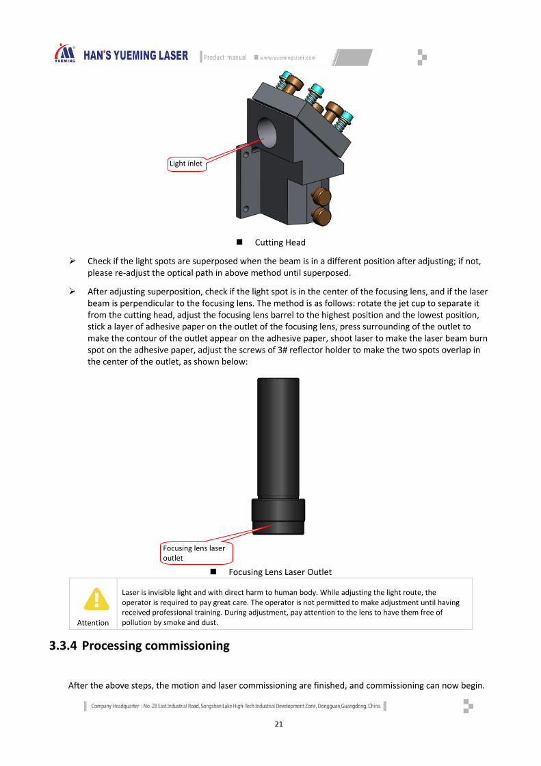
Stick a layer of adhesive paper on the inlet of 2# reflector holder, press surrounding of the inlet to make the contour of the inlet appear on the adhesive paper, adjust the screws of 1# reflector holder, and irradiate the laser beam of 1# reflector to the center of 2# reflector; if needed, adjust three adjustment screws to make the laser beam focus on the center of 2# reflector, as shown below:
Optical Path Adjustment
Attention
The positions of the light spots above are recommended to emit at the center of lens, but not the edge. In case of being at the edge, further adjustment is needed till being at the center.
When adjusting the third and fifth reflector, move the cutting head assembly to the leftmost and rightmost of the beam. Affix a layer of tape on the incident light port of the cutting head, burst laser at the burst leftmost and rightmost of the beam, to make the laser beam on the tape affixed on the incident light port of the cutting head and ablate traces of light spot, adjust the screws of the front reflector holder so that the spots superpose in the center of the incident light port;
Lens pitch angle adjustment screw
Laser irradiates to the center of this hole
21
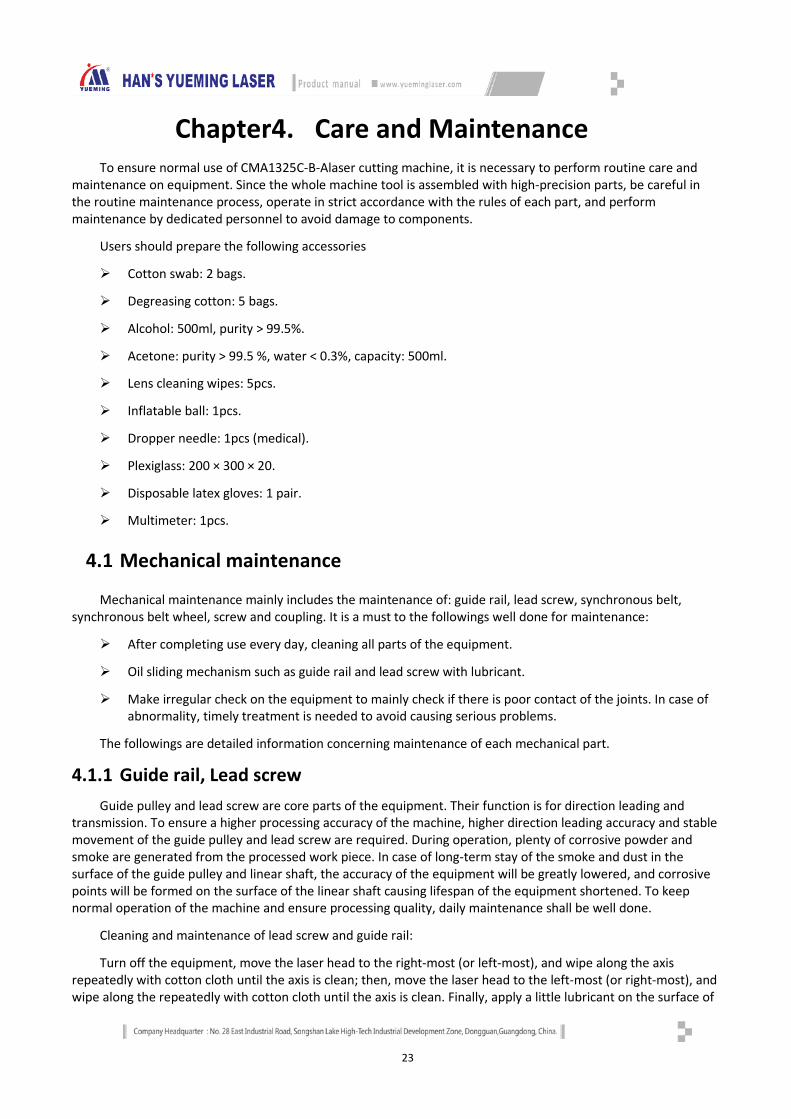
Cutting Head
Check if the light spots are superposed when the beam is in a different position after adjusting; if not, please re-adjust the optical path in above method until superposed.
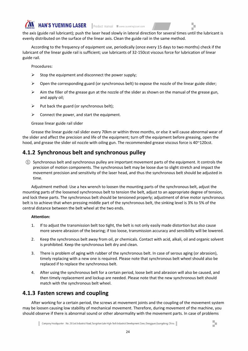
After adjusting superposition, check if the light spot is in the center of the focusing lens, and if the laser beam is perpendicular to the focusing lens. The method is as follows: rotate the jet cup to separate it from the cutting head, adjust the focusing lens barrel to the highest position and the lowest position, stick a layer of adhesive paper on the outlet of the focusing lens, press surrounding of the outlet to make the contour of the outlet appear on the adhesive paper, shoot laser to make the laser beam burn spot on the adhesive paper, adjust the screws of 3# reflector holder to make the two spots overlap in the center of the outlet, as shown below:
Focusing Lens Laser Outlet
Attention
Laser is invisible light and with direct harm to human body. While adjusting the light route, the operator is required to pay great care. The operator is not permitted to make adjustment until having received professional training. During adjustment, pay attention to the lens to have them free of pollution by smoke and dust.
3.3.4 Processing commissioning
After the above steps, the motion and laser commissioning are finished, and commissioning can now begin.
Focusing lens laser outlet
Light inlet

22
First start the equipment in power-up sequence;
Then, prepare the materials to be processed, and place the materials on the work surface horizontally;
Import or draw graphics to be processed;
Set the processing parameters (layer parameters) and related data processing technology (such as path optimization);
Adjust the distance of cutting head (non-metal processing) to make the laser focus fall on the surface of the processing materials;
Move the laser head to the processing start (find the starting point);
Start processing.
23
Chapter4. Care and Maintenance To ensure normal use of CMA1325C-B-Alaser cutting machine, it is necessary to perform routine care and
maintenance on equipment. Since the whole machine tool is assembled with high-precision parts, be careful in the routine maintenance process, operate in strict accordance with the rules of each part, and perform maintenance by dedicated personnel to avoid damage to components.
Users should prepare the following accessories
Cotton swab: 2 bags.
Degreasing cotton: 5 bags.
Alcohol: 500ml, purity > 99.5%.
Acetone: purity > 99.5 %, water < 0.3%, capacity: 500ml.
Lens cleaning wipes: 5pcs.
Inflatable ball: 1pcs.
Dropper needle: 1pcs (medical).
Plexiglass: 200 × 300 × 20.
Disposable latex gloves: 1 pair.
Multimeter: 1pcs.
4.1 Mechanical maintenance
Mechanical maintenance mainly includes the maintenance of: guide rail, lead screw, synchronous belt, synchronous belt wheel, screw and coupling. It is a must to the followings well done for maintenance:
After completing use every day, cleaning all parts of the equipment.
Oil sliding mechanism such as guide rail and lead screw with lubricant.
Make irregular check on the equipment to mainly check if there is poor contact of the joints. In case of abnormality, timely treatment is needed to avoid causing serious problems.
The followings are detailed information concerning maintenance of each mechanical part.
4.1.1 Guide rail, Lead screw Guide pulley and lead screw are core parts of the equipment. Their function is for direction leading and
transmission. To ensure a higher processing accuracy of the machine, higher direction leading accuracy and stable movement of the guide pulley and lead screw are required. During operation, plenty of corrosive powder and smoke are generated from the processed work piece. In case of long-term stay of the smoke and dust in the surface of the guide pulley and linear shaft, the accuracy of the equipment will be greatly lowered, and corrosive points will be formed on the surface of the linear shaft causing lifespan of the equipment shortened. To keep normal operation of the machine and ensure processing quality, daily maintenance shall be well done.
Cleaning and maintenance of lead screw and guide rail:
Turn off the equipment, move the laser head to the right-most (or left-most), and wipe along the axis repeatedly with cotton cloth until the axis is clean; then, move the laser head to the left-most (or right-most), and wipe along the repeatedly with cotton cloth until the axis is clean. Finally, apply a little lubricant on the surface of
24
the axis (guide rail lubricant); push the laser head slowly in lateral direction for several times until the lubricant is evenly distributed on the surface of the linear axis. Clean the guide rail in the same method.
According to the frequency of equipment use, periodically (once every 15 days to two months) check if the lubricant of the linear guide rail is sufficient; use lubricants of 32-150cst viscous force for lubrication of linear guide rail.
Procedures:
Stop the equipment and disconnect the power supply;
Open the corresponding guard (or synchronous belt) to expose the nozzle of the linear guide slider;
Aim the filler of the grease gun at the nozzle of the slider as shown on the manual of the grease gun, and apply oil;
Put back the guard (or synchronous belt);
Connect the power, and start the equipment.
Grease linear guide rail slider
Grease the linear guide rail slider every 70km or within three months, or else it will cause abnormal wear of the slider and affect the precision and life of the equipment; turn off the equipment before greasing, open the hood, and grease the slider oil nozzle with oiling gun. The recommended grease viscous force is 40~120cst.
4.1.2 Synchronous belt and synchronous pulley ① Synchronous belt and synchronous pulley are important movement parts of the equipment. It controls the
precision of motion components. The synchronous belt may be loose due to slight stretch and impact the movement precision and sensitivity of the laser head, and thus the synchronous belt should be adjusted in time.
Adjustment method: Use a hex wrench to loosen the mounting parts of the synchronous belt, adjust the mounting parts of the loosened synchronous belt to tension the belt, adjust to an appropriate degree of tension, and lock these parts. The synchronous belt should be tensioned properly; adjustment of drive motor synchronous belt is to achieve that when pressing middle part of the synchronous belt, the sinking level is 3% to 5% of the central distance between the belt wheel at the two ends.
Attention:
1. If to adjust the transmission belt too tight, the belt is not only easily made distortion but also cause more severe abrasion of the bearing; if too loose, transmission accuracy and sensibility will be lowered.
2. Keep the synchronous belt away from oil, pr chemicals. Contact with acid, alkali, oil and organic solvent is prohibited. Keep the synchronous belt dry and clean.
3. There is problem of aging with rubber of the synchronous belt. In case of serous aging (or abrasion), timely replacing with a new one is required. Please note that synchronous belt wheel should also be replaced if to replace the synchronous belt.
4. After using the synchronous belt for a certain period, loose belt and abrasion will also be caused, and then timely replacement and lockup are needed. Please note that the new synchronous belt should match with the synchronous belt wheel.
4.1.3 Fasten screws and coupling After working for a certain period, the screws at movement joints and the coupling of the movement system
may be loosen causing low stability of mechanical movement. Therefore, during movement of the machine, you should observe if there is abnormal sound or other abnormality with the movement parts. In case of problems
25
found, timely fastening and maintenance are needed. Meanwhile, the screws of the machine should be tightened one by one with tool after a certain period of use. The first fixation should be performed roughly one month later after using.
4.2 Electrical inspection
Mainly check the stability of routine supply voltage, and keep the electrical cabinet of the machine tool clean and well-ventilated. Check the integrity and safety of the lines, check if the emergency stop button functions normally, test the function of the limit switch and home switch of each axis, and check if the sensor and the drive work normally. Check if the state of button switches, indicators and warning lights is normal, diagnose and eliminate the failures of the servo system.
4.2.1 Limit switch Minimum once a month to make check on the effectiveness of limit switch of the X-axis and Y-axis. The limit
switch plays the role of restraining the limit position of the movement to avoid machine impact (overreaching) causing damage to the machine. It is a must to make regular check on working state following the steps below:
1. Start up the machine to have the laser head reset;
2. Operate the machine to make the movement shaft move to the limit positions. If the movement shaft stops at the limit position, it means a normal operation of the limit switch. If it keeps moving while reaching the limit position, it means that the limit switch is out of order.
Note
In case of hard impact occurs, please immediately press the emergency stop button to stop the machine, and find a solution for it.
4.2.2 Stop button
Stop button is the safe emergency organ of laser cutting machine; it is relative with the safety of personal property and machine. You must look-over its functions follow the following steps in the maintenance interval time of this manual.
Turn on the laser cutting machine and cutting;
Press stop button. If all the power supply of the machine has been switched off, the safe electrocircuit of stopping is normal. There are 2 stop switches, one is at machine shelves and another is on the operation terminal, you should look-over them with this method one by one.
Reset the stop button, restart the machine.
4.3 Light route and optics parts maintenance
The optical system of laser cutting machine is determined by the reflection of reflector and focusing of the focusing lens together. The focusing lens has no offset problem in the optical path. However, after a long work or due to mechanical vibration, it may cause the optical path offset. Although the reflector won’t shift when the machine is in normal use, it is recommended that the user shall check if the optical path is normal before the machine is working each time.
The optical lenses of the equipment have specular reflection and focusing effect on the laser beam. Although we have taken adequate protective measures, the material surfaces may release large amounts of corrosive gases and dust during laser cutting of the materials easy to produce dust, and the lenses can’t completely avoid these dust pollution. In addition, the lenses are precious and easily damaged under improper use, which isn’t covered by the manufacturer's warranty. Therefore, the lenses require regular cleaning and maintenance. If there is any
26
damage or serious pollution, please replace the lenses in time. It is recommended to check and clean the lenses before starting the equipment every day.
The polluted lens may cause the following consequences: 1. Effective power of the laser beam is reduced, and power loss is increased; output power is unstable; 2. Excursion of laser beam focus;
3. In case of serous pollution, the focusing lens may be broken down or burn damage to plating layer causing absolute malfunction.
Any bonding material will increase the absorption rate of the lens and reduce the service life. Therefore, please take the following preventive measures to prevent damage and contamination to the lens in the process of placing, installing and cleaning the lens:
1. Do not use suction equipment or inflatable devices to avoid scratching the lens surface;
2. Do not contact with the film directly with tools or human body when take the lens; use lens cleaning paper to isolate the tool or human body and grip the edge of the lens;
3. Do not clean the optical lenses with water or detergent. The surface of the lens is coated with a special membrane, and these materials will damage the surface of the lens
4. When installing or replacing the reflector or focusing lens, do not apply too much pressure, or else it will cause lens deformation, thus affecting the quality of the beam;
5. The lens should be tested and cleaned in dry and clean places. The surface of a good console should have several layers of clean non-woven fabric or lens cleaning paper;
6. The operator should avoid sweat or breathing gas contacting reflective surface of the lens, and keep other potential contaminants away from the work environment.
Correct cleaning method
The purpose of cleaning the lens is to clear the existing pollutants of the lens and avoid causing further pollution and damage to the lens. To achieve this purpose, please follow the steps below:
First, blow off the floats from the surface of the lens with air ball, in particular the small particles and flocculation attached to the lens surface. This step is necessary. However, do not use compressed air, because the air contains oil mist and water spray, which will deepen the pollution of the lens.
Secondly, clean the lens with acetone or ethanol. In well-lit environment, dip the lens cleaning paper or absorbent stick in acetone or ethanol, press the lens cleaning paper or cotton stick gently on the clean lens and carry out circular spiral motion from the lens center to the edge. The cleaning action must be done in one time. After cleaning, place the cleaned lens in the light to check if it is cleaned. If necessary, repeat the cleaning operation until the lens is clean.
Certainly, some pollution and lens damage cannot be removed by cleaning, e.g. film burn by dirt, film peeling off by dew or condensate water. To recover its good performance, the only way is to replace the lens.
The focusing lens is vulnerable and valuable. Follow the steps shown in the figure below during the cleaning process:

27
Fig.5-1 Focusing Lens Removal Procedure
Storage of optical lens:
Proper storage can maintain intact quality of the optical lens.
Storage temperature: 10 ~ 30 °C; do not place the lens in the freezer compartment or a similar environment, or else it is easy to damage the lens when it is taken out; the storage temperature shouldn’t be greater than 30 °C, or else it will affect the surface coating of the lens.
Store the lenses in a box and put it in an environment without vibration, or else it causes lens deformation easily and affects the lens performance.
4.4 Auxiliary equipment maintenance
4.4.1 Cleaning the fan
Clean the air ducts and fans every week to prevent affecting the ventilation effect due to debris accumulation. Check for leaks and foreign materials, and repair or cleanup. Prolonged use of fans will accumulate a lot of solid dust inside and cause a lot of noise, which is not conducive to the exhaust and odor removal. If the suction of fans is insufficient or the exhaust is impeded, turn off the power, remove the air inlet duct and outlet duct of the fan, clean the dust inside, put the fan upside down, turn the blades inside until clean and then install the fan, as shown below:
Remove the jet cup assembly
Unscrew the focusing barrel
Unscrew the pressing nut and lens washer
Take out the focusing lens (arrow indication surface is the convex surface)

28
Fig.5-2 Cleaning the Fan
4.4.2 Water chiller maintenance
The quality and temperature of cooling water directly affect the life of the laser. The cooling water must be distilled water, and the temperature must be controlled at 10°C~35°C according to the ambient temperature (±5°C); the cooling water should be kept clean and changed regularly (at least once every months), check if the cooling water is turbid, if there is sediment, and if the water temperature is too high, and replace the water; while processing, always check if the water level is adequate and if the water temperature is too high (above 35°C)
Fig.5-3 Water chiller maintenance
Remove the screws of the vent cover plate
Remove the vent cover plate, and clean the dust or debris from the air intake mesh
Then, clean the dust and debris from fan blades
29
Replace the cooling water in the following steps:
1. Turn off the laser power, and stop the machine;
2. Unscrew the drain valve of the water chiller, and drain the cooling water from the water chiller;
3. If there is any precipitate, wipe with a clean towel;
4. Open the protective cover of the water chiller, and fill the new distilled water into the water chiller;
5. Start the machine, and it will work properly when the laser tube is filled with cooling water.
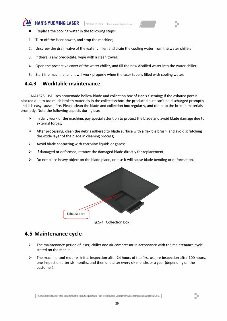
4.4.3 Worktable maintenance
CMA1325C-BA uses homemade hollow blade and collection box of Han's Yueming; if the exhaust port is blocked due to too much broken materials in the collection box, the produced dust can’t be discharged promptly and it is easy cause a fire. Please clean the blade and collection box regularly, and clean up the broken materials promptly. Note the following aspects during use:
In daily work of the machine, pay special attention to protect the blade and avoid blade damage due to external forces;
After processing, clean the debris adhered to blade surface with a flexible brush, and avoid scratching the oxide layer of the blade in cleaning process;
Avoid blade contacting with corrosive liquids or gases;
If damaged or deformed, remove the damaged blade directly for replacement;
Do not place heavy object on the blade plane, or else it will cause blade bending or deformation.
Fig.5-4 Collection Box
4.5 Maintenance cycle
The maintenance period of laser, chiller and air compressor in accordance with the maintenance cycle stated on the manual.
The machine tool requires initial inspection after 24 hours of the first use, re-inspection after 100 hours, one inspection after six months, and then one after every six months or a year (depending on the customer).
Exhaust port
30
4.6 Runtime maintenance
Before running the machine tool, check machine tool every day as required. If there is abnormal sound when the machine tool is running, shut down and check immediately. After the machine is running, shut down in required sequence, clean the work table of the machine tool and around machine, and do not place unrelated items on the work table or console of the machine.
① Regularly check the lubrication of the moving parts of the machine tool, ensure sufficient lubrication of X-axis rail, Y-axis rail, Z-axis rail and screw seat, ensure the accuracy of the machine tool, keep lubrication of all moving parts and extend the life of X-axis, Y-axis and Z-axis rails;
② Check the air pipe and water pipe for damage weekly; if damaged, inform Han's Yueming Laser for maintenance;
③ Clean the debris and dust from the air inlet and outlet, and filter screen of the machine tool weekly;
④ Check the level of the cooling water weekly, and fill up in time if insufficient;
⑤ Check the pollution of the reflector and focusing lens surface every two weeks, and clean the optical lens in time to ensure its service life;
⑥ Check the outer optical path once every month; the optical path directly affects the cutting results;
⑦ Check the filter in the gas path once every month, and remove the water and debris from the filter;
⑧ Regularly check if external cables are scratched, and if the interfaces in the power distribution cabinet loose;
⑨ After the machine tool is installed and used for six months, readjust the level of the machine tool to ensure the cutting precision;
4.7 Maintenance of long-term shutdown
If the machine tool will be shut down for long time, please lubricate the moving parts of the machine and wrap in rust-proof paper. For other parts, regularly check for rusting, process the rusting parts (add dust cover if possible), regularly clean and check the machine.
31
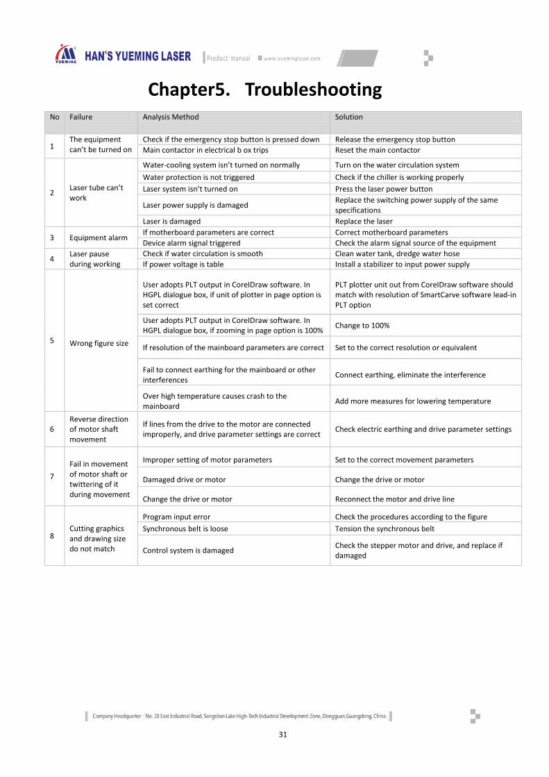
Chapter5. Troubleshooting
No Failure Analysis Method Solution
1 The equipment can’t be turned on
Check if the emergency stop button is pressed down Release the emergency stop button Main contactor in electrical b ox trips Reset the main contactor
2 Laser tube can’t work
Water-cooling system isn’t turned on normally Turn on the water circulation system Water protection is not triggered Check if the chiller is working properly Laser system isn’t turned on Press the laser power button
Laser power supply is damaged Replace the switching power supply of the same specifications
Laser is damaged Replace the laser
3 Equipment alarm If motherboard parameters are correct Correct motherboard parameters Device alarm signal triggered Check the alarm signal source of the equipment
4 Laser pause during working
Check if water circulation is smooth Clean water tank, dredge water hose If power voltage is table Install a stabilizer to input power supply
5 Wrong figure size
User adopts PLT output in CoreIDraw software. In HGPL dialogue box, if unit of plotter in page option is set correct
PLT plotter unit out from CoreIDraw software should match with resolution of SmartCarve software lead-in PLT option
User adopts PLT output in CoreIDraw software. In HGPL dialogue box, if zooming in page option is 100% Change to 100%
If resolution of the mainboard parameters are correct Set to the correct resolution or equivalent
Fail to connect earthing for the mainboard or other interferences Connect earthing, eliminate the interference
Over high temperature causes crash to the mainboard Add more measures for lowering temperature
6 Reverse direction of motor shaft movement
If lines from the drive to the motor are connected improperly, and drive parameter settings are correct Check electric earthing and drive parameter settings
7 Fail in movement of motor shaft or twittering of it during movement
Improper setting of motor parameters Set to the correct movement parameters
Damaged drive or motor Change the drive or motor
Change the drive or motor Reconnect the motor and drive line
8 Cutting graphics and drawing size do not match
Program input error Check the procedures according to the figure Synchronous belt is loose Tension the synchronous belt
Control system is damaged Check the stepper motor and drive, and replace if damaged
32
Chapter6. Transportation, Shipment and Storage
6.1 Packaging
CMA1325C-B-AThe chiller, laser and accessories of CMA1325C-G-A laser cutting machine are packed in wooden cases. Other parts are wrapped with PE foam and protective film to protect external objects damaging any part of the laser cutting machine.
6.2 Transport and shipment method and precautions
Do not climb or stand on the crate, or place any heavy objects on the crate.
Do not drag or carry the product with cables connected to the product.
Do not impact or scratch the panel and the display.
The crate should be protected from moisture, exposure in the sun and rain.
When lifting the machine, handle gently to avoid collision. The wire rope shouldn’t scratch the machine while lifting; if unavoidable, isolate with soft objects.
6.3 Storage conditions, period and precautions
The storage environment of the machine should avoid the rain, moisture, inclining, rodents, potholes and other hazards and ensure good ventilation. The storage ambient temperature should be -10°C ~ +40°C, and relative humidity is not higher than 85%. For the transport and storage less than 24 hours, the ambient temperature shouldn’t exceed 60°C. It is prohibited to store in open air for a long time. If temporary storage is required, in addition to the above requirements, check the storage conditions and packaging state to ensure the machine from damage.
33
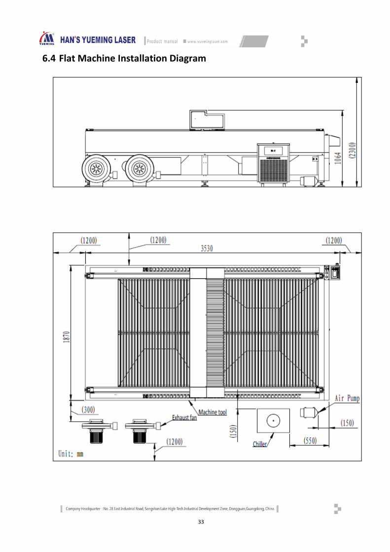
6.4 Flat Machine Installation Diagram
34
Postscript All final right of interpretation of this manual belongs to GD HAN’S YUEMIGN LASER GROUP CO., LTD; we will
do our utmost efforts to ensure the accuracy of the contents of this manual. We do not assume any responsibility caused by misspellings and typing errors. Your comments will be highly appreciated.
All rights reserved! Reprinting or copy without permission is prohibited. We reserve the right of lawing.
07020101377 CNY:50.00


