The patent pending Adult Triple Action 2.0 ankle joint offers unique features and exceptional performance for the orthotic treatment of stroke, traumatic brain injury and other pathologic neuromusculoskeletal conditions. It has been shown to systematically influence gait in biomechanical studies.
The component is easy to use and separates the action of plantarflexion resistance, dorsiflexion resistance, range of motion and alignment.
Triple Action springs are many times stronger and last longer than springs used in conventional orthotic components. The clinician can tune the component to meet the changing needs of their patient through all stages of recovery and rehabilitation. This adjustability delivers an effective orthotic solution to help mobilize the ankle, while balancing support for the knee.
The component may also be used post-surgically or as a static progressive management tool for adjustable static alignment followed by progressive mobilization of the ankle.
Triple Action delivers active support to help patients navigate the real world outside the exam room.
INTRODUCTION
®
Adult Ankle Joint 2.0
Models
Model 3A76Adult Triple Action 2.0 ankle joint with Lateral Stirrup option(Model 3A76-LATR shown)
Model 3A76-BSAdult Triple Action 2.0 ankle joint with Non-removable PF Booster Spring and Lateral Stirrup option(Model 3A76-BS-LATR shown)
(1.5mm) New pivot bearing for single upright applications.
1.
®
Adult Ankle Joint 2.0
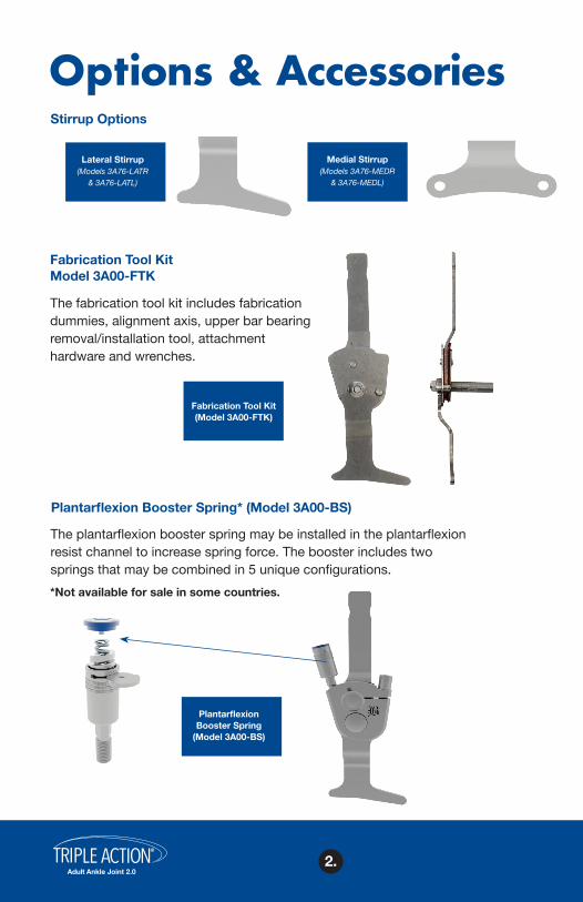
Options & Accessories
Lateral Stirrup(Models 3A76-LATR
& 3A76-LATL)
Medial Stirrup(Models 3A76-MEDR
& 3A76-MEDL)
Stirrup Options
2.
Plantarflexion Booster Spring* (Model 3A00-BS)
The plantarflexion booster spring may be installed in the plantarflexion resist channel to increase spring force. The booster includes two springs that may be combined in 5 unique configurations.
Plantarflexion Booster Spring
(Model 3A00-BS)
*Not available for sale in some countries.
Fabrication Tool KitModel 3A00-FTK
The fabrication tool kit includes fabrication dummies, alignment axis, upper bar bearing removal/installation tool, attachment hardware and wrenches.
Fabrication Tool Kit (Model 3A00-FTK)
®
Adult Ankle Joint 2.0
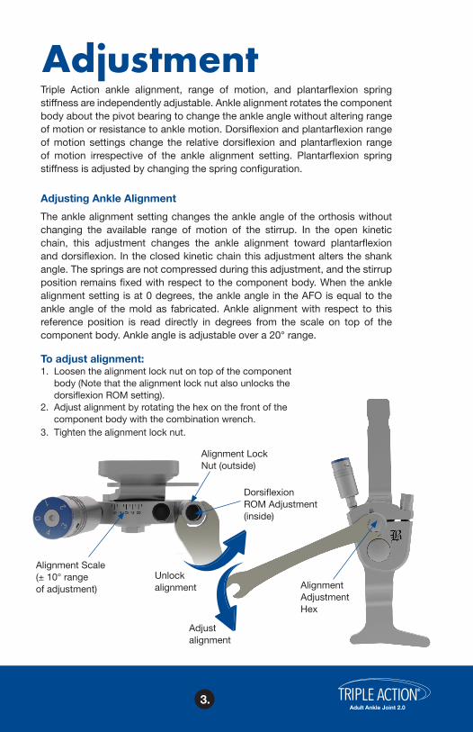
AdjustmentTriple Action ankle alignment, range of motion, and plantarflexion spring stiffness are independently adjustable. Ankle alignment rotates the component body about the pivot bearing to change the ankle angle without altering range of motion or resistance to ankle motion. Dorsiflexion and plantarflexion range of motion settings change the relative dorsiflexion and plantarflexion range of motion irrespective of the ankle alignment setting. Plantarflexion spring stiffness is adjusted by changing the spring configuration.
Adjusting Ankle AlignmentThe ankle alignment setting changes the ankle angle of the orthosis without changing the available range of motion of the stirrup. In the open kinetic chain, this adjustment changes the ankle alignment toward plantarflexion and dorsiflexion. In the closed kinetic chain this adjustment alters the shank angle. The springs are not compressed during this adjustment, and the stirrup position remains fixed with respect to the component body. When the ankle alignment setting is at 0 degrees, the ankle angle in the AFO is equal to the ankle angle of the mold as fabricated. Ankle alignment with respect to this reference position is read directly in degrees from the scale on top of the component body. Ankle angle is adjustable over a 20° range.
To adjust alignment:1. Loosen the alignment lock nut on top of the component
body (Note that the alignment lock nut also unlocks the dorsiflexion ROM setting).
2. Adjust alignment by rotating the hex on the front of the component body with the combination wrench.
3. Tighten the alignment lock nut.
Alignment Scale (± 10° range of adjustment)
Adjust alignment
Unlock alignment
Dorsiflexion ROM Adjustment (inside)
Alignment Lock Nut (outside)
Alignment Adjustment Hex
3.
®
Adult Ankle Joint 2.0
Adjusting Dorsiflexion Range of Motion The dorsiflexion range of motion adjustment changes the stirrup range of motion between its neutral position (at the alignment ankle angle) and the dorsiflexion motion limiting stop.
To zero dorsiflexion ROM:• Loosen the alignment lock nut on top of the
component body.• While holding the nut with the combination wrench,
turn the DF ROM adjustment screw fully clockwise using the 4mm adjustment wrench.
• Tighten the alignment lock nut.
To adjust dorsiflexion ROM:• Loosen the alignment lock nut on top of the
component body.• Turn the adjustment screw counter clockwise to
increase DF ROM 3° per full turn while holding the alignment lock nut.
• Tighten the alignment lock nut.
Notes:• The maximum DF ROM setting is 12° (4 turns
of the adjustment screw).• Count the number of turns to keep track of
the setting.• If the alignment setting changes during this
adjustment, return alignment to the desired setting before tightening the alignment lock nut.
Increase DF ROM (inside)
Alignment Lock Nut (outside) must be loosened to adjust DF ROM
Adjusting DorsiflexionROM
Staged Dorsiflexion Resistance
The dorsiflexion resist function uses two springs installed in the anterior channels of the component body. The middle spring is the “2nd rocker spring” and the anterior-most spring is the “terminal stance spring.” The 2nd rocker spring is lower stiffness and its range of motion (ROM) is not adjustable. The terminal stance spring is high stiffness, it’s ROM is adjustable and determines the overall ROM of the component in dorsiflexion. Adjusting the dorsiflexion ROM setting between 0° and 6° applies high active resistance to dorsiflexion using both the 2nd rocker and terminal stance springs. If the dorsiflexion ROM setting is adjusted between 6° and 12°, the 2nd rocker spring acts alone through the first 6° of stirrup articulation before the terminal stance spring is encountered. When the terminal stance spring is encountered, the stiffness and resistance to dorsiflexion increase rapidly to the end of ROM. The stirrup angle at which terminal stance spring is encountered is adjusted by the dorsiflexion ROM setting. This patent-pending Triple Action feature is called “Staged Resistance.”
4.
®
Adult Ankle Joint 2.0
Adjusting Plantarflexion Range of Motion (Model 3A76)The plantarflexion range of motion adjustment changes the stirrup range of motion between its neutral position (at the alignment ankle angle) and the plantarflexion motion limiting stop.
To zero plantarflexion ROM:• Turn the plantarflexion ROM adjustment screw fully clockwise
using the 4mm adjustment wrench.
To adjust plantarflexion ROM:• Turn the adjustment screw counter clockwise to increase
plantarflexion ROM 5° per full turn.
Notes:• The maximum PF ROM setting is 12° (2½ turns of the adjustment screw).• Count the number of turns to keep track of the setting.• The plantarflexion ROM adjustment screw is pre-coated with an antimigration
patch and does not require thread locking adhesive for the first five adjustments.
Adjusting Plantarflexion ROM with the PF Booster Spring Installed Model 3A76-BS or 3A00-BS*With the PF Booster Spring installed, rotate the booster to adjust the PF ROM setting.
To zero plantarflexion ROM
Figure 1. Unlock the PF ROM Adjustment using the 1.5mm hex wrench.
Figure 2. Adjust the PF ROM setting to 0° by turning the Booster fully clockwise with the adjustment wrench.
Figure 3. Loosen the ROM Dial screw using the 2mm adjustment wrench and zero the PF ROM setting by turning the blue ROM dial. The plantarflexion channel side of the component body serves as a reference for this adjustment.
Increase PF ROM
5.
*Not available for sale in some countries.
®
Adult Ankle Joint 2.0
Adjusting Plantarflexion ROM with the PF Booster Spring Installed Model 3A76-BS or 3A00-BS* Cont.To adjust plantarflexion ROM with the PF Booster:• Loosen the Booster lock screw to unlock the adjustment
(Figure 1).• Turn the Booster counter clockwise to increase PF ROM 5°
per turn.• Lock the booster by tightening the Booster lock screw (Figure 1).Notes:• The maximum PF ROM setting is 12° (2½ turns of the Booster).• The PF ROM is read directly from the blue PF ROM Dial.
Adjusting Plantarflexion Spring StiffnessThe stiffness of plantarflexion spring configuration 1a or 1b is suitable for the management of mild swing phase gait deficits. If higher plantarflexion stiffness is required, the plantarflexion Booster Spring (Model 3A76-BS or 3A00-BS) may be installed. With the Booster Spring installed, the component’s plantarflexion resist can be configured with five different stiffness options.
Model 3A76-BS or 3A00-BS
PF Spring Configuration 1a or 1b 2 3* 4 5
Booster Required No Yes Yes Yes Yes
Bottom Spring Standard (blue)
Standard (blue) Pin Guide Standard
(blue)Standard
(blue)
Top Spring None Standard (blue) High (silver) High (silver)
Configuring the PF Booster SpringThe stiffness of plantarflexion spring configuration 1a (or 1b) is about 3 times higher than a conventional metal ankle joint.
With the booster spring installed, spring stiffness increases linearly with the spring configuration number. Spring configuration 5 is about 18 times stiffer than a conventional metal ankle joint. The maximum active ROM for all plantarflexion spring options is 12 degrees.
To change the booster spring configuration:1. Increase the plantarflexion ROM setting to 15˚ by turning the
booster counter clockwise to decrease booster spring compression (Figure 4).
2. Remove the plantarflexion booster ROM dial zero screw and plantarflexion ROM Dial (Figure 5).
3. Remove the Keeper Plate and install the desired spring configuration (Figure 6).
Figure 4. Adjust the Booster to 15° ROM.
Figure 5. Remove the ROM Dial Zero Screw and
PF ROM dial.
Figure 6. Remove the Keeper Plate and
Install the desired spring configuration.
ROM Dial Zero Screw
PF ROM Dial
Top Spring (Standard)
Keeper Plate
Top Spring(High)
Booster Housing
Bottom Spring
7.
®
Adult Ankle Joint 2.0
Orthotic Design ConsiderationsFor best results, Triple Action AFOs must be rigid. AFOs that are too flexible will decrease the systematic influence of the Triple Action ankle joint on gait. Rigid carbon/epoxy laminated orthoses are recommended for Adult Triple Action AFOs. Ribs of stiffeners may also be included to help stiffen the structure. If single upright designs are used, attention should be given to enhancing torsional stiffness of the tibial section.
Depending on spasticity, a single Triple Action component placed on the lateral or medial side may be suitable for the management of patients up to 90 Kg (200 lbs). For spastic patients greater than 90 Kg, bilateral Triple Action components are recommended.
Anterior (ventral) AFO designs (Figure 7) with full length footplates are recommended when dorsiflexion resist function predominates, such as in sub-acute stroke or TBI management/rehabilitation, or where there is a quadriceps or plantarflexor insufficiency. Posterior (dorsal) AFO designs (Figure 8) with sulcus or full-length footplates are recommended when there is high plantarflexion spasticity, or knee extension in the early stance phase of gait, such as in extensor synergy in chronic stroke.
Triple Action® Clinical Tuning ProcedureThrough biomechanical research, Becker Orthopedic has developed a clinical tuning procedure to help simplify application of the Triple Action® ankle joint. This procedure is intended as a starting point to allow clinicians to more quickly arrive at optimal component settings using Observational Gait Analysis.
Spring SelectionBefore performing Bench Adjustment, the desired Triple Action plantarflexion spring configuration must be installed (refer to Adjusting PF Spring Stiffness).
The Adult Triple Action ankle joint, model 3A76, with spring configuration 1a in the plantarflexion channel is suitable for the management of patients with mild swing and stance phase gait deficits under 80Kg (180lbs). For patients with higher spasticity or greater weight the booster spring, models 3A76-BS or 3A00-BS, is recommended. In general, higher stiffness springs should be used to manage higher spasticity patients.
Models 3A76-BS or 3A76 with the 3A00-BS plantarflexion booster spring expands applications of the Triple Action to patients with a broad range of neuromusculoskeletal deficits. All plantarflexion spring options have 12° ROM and stiffness increases linearly with PF spring configuration number.
Bench AdjustmentAfter the desired PF spring configuration has been installed and prior to fitting the orthosis, bench adjust the component as follows:1. Adjust the plantarflexion ROM setting to 0°.2. Adjust the dorsiflexion ROM setting to 0°.3. Set the ankle alignment to 0°.
9.
®
Adult Ankle Joint 2.0
Static Alignment (PF and DF ROM at 0°)Don the orthosis and shoes to the patient and perform static alignment with the patient standing. Adjust the ankle angle with the ROM settings locked at 0° to tune for knee stability. The knee should be slightly flexed to place the weight line over the midfoot and improve the patient’s sense of standing balance and stability. Avoid aligning the ankle to the patient’s maximum ROM in dorsiflexion when making this adjustment. If there is insufficient dorsiflexion ROM to make this adjustment due to a gastrosoleus contracture, a heel lift or shoe modification may be necessary.
Toe Clearance (left) and Foot to Floor Angle (right)
Swing Phase Alignment (PF and DF ROM at 0°)With the patient walking, and the ROM settings still locked at 0°, adjust the alignment setting to improve toe clearance in mid swing and foot position at initial contact. Observe the foot to floor angle while making this adjustment. Note that increasing dorsiflexion alignment may reduce knee extension at terminal swing if there is gastrocnemius tone or contracture. Also observe and optimize for step length symmetry while making this adjustment.
10.
®
Adult Ankle Joint 2.0
Early Stance Phase Adjustment(DF ROM at 0°)Increase plantarflexion ROM 5° to 10° (1 to 2 turns of the adjustment screw or booster spring) to activate the ankle in 1st rocker and early stance. Increasing PF ROM will decrease the pre-load resistance of the PF resist. Ensure that toe clearance and foot position at initial contact are maintained as PF ROM is increased.
• If toe clearance or foot to floor angle decreases Decrease the PF ROM.
• If knee hyperextension in early stance increases Decrease the PF ROM.
• If the knee flexes excessively in 1st rocker Increase the PF ROM.
If plantarflexion ROM must be decreased to less than 5° to maintain ankle position during this adjustment, it may be necessary to increase the stiffness of the plantarflexion spring by changing the spring configuration to a higher number using the Booster Spring (Models 3A76-BS or 3A00-BS).
Late Stance Phase AdjustmentAdjust dorsiflexion ROM to activate the anklein 2nd rocker and late stance to stabilize theknee. Begin by increasing the dorsiflexion (DF) ROM by 1 to 2-turns (3 to 6°) of the adjustment screw.
• If the knee flexes excessively after midstance Decrease the DF ROM.
• If the knee hyperextends at the end of stance phase Increase the DF ROM.
11.
®
Adult Ankle Joint 2.0
MaintenanceDisassemblyUse the following procedure to disassemble the component for fabrication and maintenance:
1. Remove the alignment bushing screw using a large slotted screwdriver.2. Remove the pivot bushing screw using the 2mm hex wrench.3. Remove the upper bar pivot bushing and upper bar.4. Remove the front pivot bushing.5. Remove the stirrup.
Notes: a. Use the Bearing Removal/Installation Tool (Figure 9) included with the
Fabrication Tool Kit (Model 3A00-FTK) to remove the pivot bearing from the upper bar prior to lamination to avoid contamination with resin.
b. An arbor press or the quill feed of an unpowered drill press should be used with the tool to gently push the bearing out of the bar.
Figure 9. Removing the Upper Bar Pivot Bearing.
1.2.
3.
4.
5.
Figure 10. Cam Clip.
12.
®
Adult Ankle Joint 2.0
MaintenanceAssemblyThe Adult Triple Action ankle joint requires minimal maintenance. The pivot bearings in the upper bar and component body should be lubricated on a monthly basis using a small drop of oil. The pivot screw and cam screw should be coated with medium strength thread locking adhesive prior to final assembly. Note that the bar attachment screws (not included) should also be coated with thread locking adhesive prior to final assembly.
1. I nstall and lubricate the cam clip (Figure 10) with SAE 30W oil. Ensure that the cam clip is oriented correctly in the cam slot with the open end of the clip toward the pivot bearing.2. Lubricate the bearing shoulder of the male pivot bushing with SAE 30W oil.3. Lubricate the bearing shoulder of the female pivot bushing with SAE 30W oil.4. Apply medium strength thread locker to the pivot screw and install.5. Apply medium strength thread locker to the cam screw and install.
Notes: a. All motion limiter pins should be lubricated with a high viscosity grease
prior to installation. b. The upper bar pivot bearing must be installed using the Bearing Removal/
Installation Tool (Figure 11) included with the Fabrication Tool Kit (Model 3A00-FTK). Use care not to damage the pivot bearing during installation.
Figure 10. Cam Clip.
Figure 11. Installing the Upper Bar Pivot Bearing.