57
Product Planning Guide Office Locations Minnetonka, Minnesota Thunder Bay, Ontario

Product Planning Guide
Office Locations
Minnetonka, Minnesota
Thunder Bay, Ontario

Telecom Engineering © 2011 r1
Overview
This guide explains how Telecom Engineering products
and services can help expand your fiber optic network.

Telecom Engineering © 2011 r1
Typical Dark Fiber Link
Customer begins with a fiber cable with 1 or 2 available dark fiber strands
between two end locations terminating in fiber distribution panels (FDP,
a.k.a. fiber patch panels).
Multiple fiber strands
FDP FDP
Location A Location Z
Fiber Cable Length L
Telecom Engineering © 2011 r1
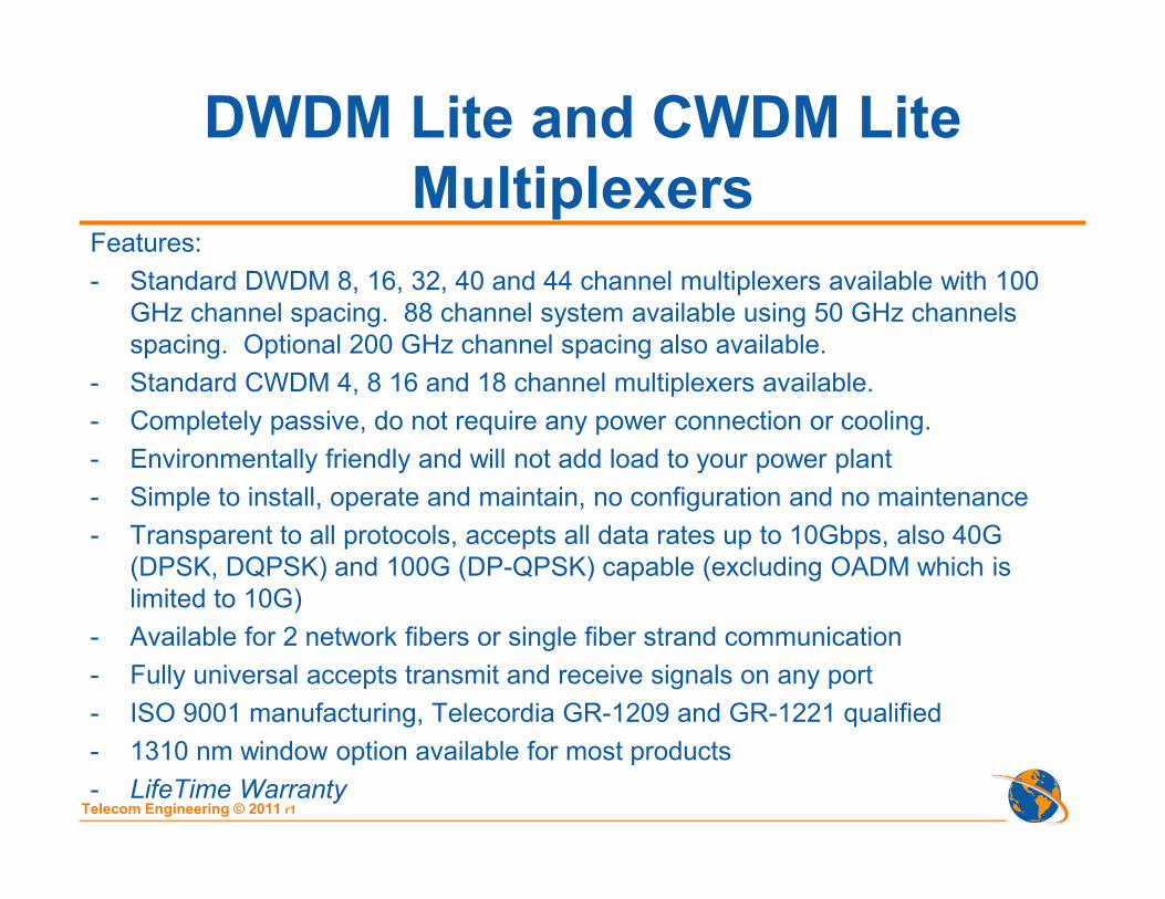
DWDM Lite and CWDM Lite
MultiplexersFeatures:
- Standard DWDM 8, 16, 32, 40 and 44 channel multiplexers available with 100
GHz channel spacing. 88 channel system available using 50 GHz channels
spacing. Optional 200 GHz channel spacing also available.
- Standard CWDM 4, 8 16 and 18 channel multiplexers available.
- Completely passive, do not require any power connection or cooling.
- Environmentally friendly and will not add load to your power plant
- Simple to install, operate and maintain, no configuration and no maintenance
- Transparent to all protocols, accepts all data rates up to 10Gbps, also 40G
(DPSK, DQPSK) and 100G (DP-QPSK) capable (excluding OADM which is
limited to 10G)
- Available for 2 network fibers or single fiber strand communication
- Fully universal accepts transmit and receive signals on any port
- ISO 9001 manufacturing, Telecordia GR-1209 and GR-1221 qualified
- 1310 nm window option available for most products
- LifeTime Warranty

Telecom Engineering © 2011 r1
CWDM Lite Multiplexers
(dual fiber)Customer adds dual fiber CWDM Lite multiplexers to increase fiber link capacity up
to a maximum of 18 channels (18 CWDM wavelengths 1271nm to 1611nm).
2 fiber strands
FDP FDP
Location A Location Z
CWDM Lite
Mux/Demux
CWDM Lite
Mux/Demux
Ch 1
Ch 18
Notes:
4ch (4wave) IL=2.4dB M&D pair; 16ch (16wave) IL=4.8dB M&D pair
8ch (8wave) IL=3.5dB M&D pair; 18ch (18wave) IL=5.2dB M&D pair
Ch 1
Ch 18

Telecom Engineering © 2011 r1
CWDM Lite Multiplexers
8 channel, dual fiber

Telecom Engineering © 2011 r1
CWDM Lite Multiplexers
(single fiber)Customer adds dual fiber CWDM Lite multiplexers to increase fiber link capacity to
maximum 9 channels.
1 fiber strand
FDP FDP
Location A Location Z
CWDM Lite
Mux/Demux
CWDM Lite
Mux/Demux
Ch 1Tx
Ch 9Tx
Ch 10Tx
Ch 18Tx
Notes:
2ch (4wave) IL=2.4dB M&D pair; 8ch (16wave) IL=4.8dB M&D pair
4ch (8wave) IL=3.5dB M&D pair; 9ch (18wave) IL=5.2dB M&D pair

Telecom Engineering © 2011 r1
CWDM Lite Optical Add/Drop
Multiplexers OADM (dual fiber)Customer inserts dual fiber CWDM Lite OADM multiplexer to add/drop 1 to 4
channels (1471nm to 1611nm only). Rate 10G and less.
FDP FDPLocation A Location Z
CWDM Lite
Mux/DemuxCWDM Lite
Mux/Demux
Ch 1
Ch 8
Ch 1
Ch 8
W E
1 to 4 Ch
West
Traffic
1 to 4 Ch
East
Traffic
D.
CWDM OADM
Notes:
2ch (2wave) IL WE=1.3dB, IL drop=1.3dB
4ch (4wave) IL WE=2.3dB, IL drop=1.5dB
2 fiber strands

Telecom Engineering © 2011 r1
CWDM Lite OADM
2 channel, dual fiber

Telecom Engineering © 2011 r1
CWDM Lite Optical Add/Drop
Multiplexers OADM (single fiber)Customer inserts dual fiber CWDM Lite OADM multiplexer to add/drop 1 to 2
channels (1471nm to 1611nm only). Rate 10G and less.
1 fiber strand
FDP
FDPLocation A Location Z
CWDM Lite
Mux/DemuxCWDM Lite
Mux/Demux
Ch 1Tx
Ch 4Tx
Ch 5Tx
Ch 8Tx
W E
5 to 6 Ch
Tx West
1 to 2 Ch
Tx East
D.
CWDM OADM
Notes:
1ch (2wave) IL WE=1.3dB, IL drop=1.3dB
2ch (4wave) IL WE=2.3dB, IL drop=1.5dB

Telecom Engineering © 2011 r1
CWDM Lite OADM
2 channel, single fiber

Telecom Engineering © 2011 r1
DWDM Lite Multiplexers
(dual fiber)Customer adds dual fiber DWDM Lite multiplexers to increase fiber link capacity to
maximum 44 channels 100 GHz ch spacing (optional 50 GHz channel spacing with
88 channel mux/demux is available).
2 fiber strands
FDP FDP
Location A Location Z
DWDM Lite
Mux/Demux
DWDM Lite
Mux/Demux
Ch 1
Ch 44
Ch 1
Ch 44
Notes:
8ch (8wave) IL=4.5dB M&D pair; 32ch (32wave) IL=6.3dB M&D pair
16ch (16wave) IL=6.0dB M&D pair; 44ch (44wave) IL=7.5dB M&D pair

Telecom Engineering © 2011 r1
DWDM Lite Multiplexers
(single fiber)Customer adds dual fiber DWDM Lite multiplexers to increase fiber link capacity to
maximum 22 channels.
1 fiber strand
FDP FDP
Location A Location Z
DWDM Lite
Mux/Demux
DWDM Lite
Mux/Demux
Ch 1Tx
Ch 22Tx
Ch 23Tx
Ch 44Tx
Notes:
4ch (8wave) IL=4.5dB M&D pair; 16ch (32wave) IL=6.3dB M&D pair
8ch (16wave) IL=6.0dB M&D pair; 22ch (44wave) IL=7.5dB M&D pair

Telecom Engineering © 2011 r1
DWDM Lite Multiplexers
40 channel, single fiber

Telecom Engineering © 2011 r1
DWDM Lite Optical Add/Drop
Multiplexers OADM (dual fiber)Customer inserts dual fiber DWDM Lite OADM multiplexer to add/drop 1 to 16
channels. Rate 10G and less.
2 fiber strandsFDP FDP
Location A Location Z
DWDM Lite
Mux/DemuxDWDM Lite
Mux/Demux
Ch 1
Ch 44
Ch 1
Ch 44
W E
1 to 16 Ch
West Traffic
1 to 16 Ch
East Traffic
D.
DWDM OADM
Notes:
2ch (2wave) IL WE=1.5dB, IL Drop=1.9dB; 8ch (8wav) IL WE=1.2dB, IL Drop=3.8dB
4ch (4wave) IL WE=1.2dB, IL Drop=2.7dB; 16ch (16wav) IL WE=1.8dB, ILDrop=4.5dB

Telecom Engineering © 2011 r1
DWDM Lite OADM
4 channel, dual fiber

Telecom Engineering © 2011 r1
DWDM Lite Optical Add/Drop
Multiplexers OADM (single fiber)Customer inserts dual fiber DWDM Lite OADM multiplexer to add/drop 1 to 8
channels. Rate 10G and less.
1 fiber strandFDP FDP
Location A Location Z
DWDM Lite
Mux/DemuxDWDM Lite
Mux/Demux
Ch 1Tx
Ch 22Tx
Ch23Tx
Ch44Tx
W E
23 to 31 Ch
Tx West
1 to 8 Ch
Tx East
D.
DWDM OADM
Notes:
1ch (2wave) IL WE=1.5dB, IL Drop=1.9dB; 4ch (8wav) IL WE=1.2dB, IL Drop=3.8dB
2ch (4wave) IL WE=1.2dB, IL Drop=2.7dB; 8ch (16wav) IL WE=1.8dB, ILDrop=4.5dB

Telecom Engineering © 2011 r1
CWDM Lite M-ROADM
(dual fiber)Customer inserts dual fiber CWDM Lite M-ROADM multiplexer to add/drop 1 to 18
channels.
2 fiber strandsFDP FDPLocation A Location Z
CWDM Lite
Mux/DemuxCWDM Lite
Mux/Demux
Ch 1
Ch 18
Ch 1
Ch 18
W E
1 to 18 Ch
West Traffic
1 to 18 Ch
East Traffic
D.
CWDM M-ROADM
Notes:
8ch (8wave) IL WE=3.5dB, IL Drop=3.0dB; 18ch (18wav) IL WE=5.5dB, ILDrop=4.5dB
16ch (16wav) IL WE=5.0dB, IL Drop=4.5dB

Telecom Engineering © 2011 r1
CWDM Lite M-ROADM
8 channel, dual fiber

Telecom Engineering © 2011 r1
CWDM Lite M-ROADM
(single fiber)Customer inserts dual fiber CWDM Lite M-ROADM multiplexer to add/drop 1 to 9
channels.
1 fiber strandsFDP FDPLocation A Location Z
CWDM Lite
Mux/DemuxCWDM Lite
Mux/Demux
Ch 1Tx
Ch 9Tx
Ch 10Tx
Ch 18Tx
W E
10 to 18 Ch
Tx West
1 to 9 Ch
Tx East
D.
CWDM M-ROADM
Notes:
4ch (8wave) IL WE=3.5dB, IL Drop=3.0dB; 9ch (18wav) IL WE=5.5dB, ILDrop=4.5dB
8ch (16wav) IL WE=5.0dB, IL Drop=4.5dB

Telecom Engineering © 2011 r1
DWDM Lite M-ROADM
(dual fiber)Customer inserts dual fiber DWDM Lite M-ROADM multiplexer to add/drop 1 to 44
channels.
2 fiber strandsFDP
FDPLocation A Location Z
DWDM Lite
Mux/DemuxDWDM Lite
Mux/Demux
Ch 1
Ch 44
Ch 1
Ch 44
W E
1 to 44 Ch
West Traffic
1 to 44 Ch
East Traffic
D.
DWDM M-ROADM
Notes:
8ch (8wave) IL WE=3.5dB, IL Drop=3.0dB; 32ch (32wav) IL WE=5.5dB, ILDrop=4.5dB
16ch (16wav) IL WE=5.0dB, IL Drop=4.5dB; 44ch (44wav) IL WE=7.5dB,ILDrop=5.5dB

Telecom Engineering © 2011 r1
DWDM Lite M-ROADM
16 channel, dual fiber

Telecom Engineering © 2011 r1
DWDM Lite M-ROADM
(single fiber)Customer inserts dual fiber DWDM Lite M-ROADM multiplexer to add/drop 1 to 22
channels.
1 fiber strandsFDP FDPLocation A Location Z
DWDM Lite
Mux/DemuxDWDM Lite
Mux/Demux
Ch 1Tx
Ch 22Tx
Ch 23Tx
Ch 44Tx
W E
23 to 44 Ch
Tx West
1 to 22 Ch
Tx East
D.
DWDM M-ROADM
Notes:
4ch (8wave) IL WE=3.5dB, IL Drop=3.0dB; 16ch (32wav) IL WE=5.5dB, ILDrop=4.5dB
8ch (16wav) IL WE=5.0dB, IL Drop=4.5dB; 22ch (44wav) IL WE=7.5dB,ILDrop=5.5dB

Telecom Engineering © 2011 r1
WDM Lite Cross Band Multiplexers
(dual fiber)Customer adds dual fiber WDM Lite 1310nm / 1550 nm cross band multiplexers to
increase fiber link capacity to 2 channels, 1310nm and 1550nm. Advantage, double
link bandwidth by using commonly available 1310nm and 1550nm transceivers
2 fiber strands
FDP FDP
Location A Location Z
WDM Lite
Cross Band
WDM Lite
Cross Band
Ch 1
1310nm
Ch 2
1550nm
Ch 1
1310nm
Ch 2
1550nm
Notes:
2ch (2wave) IL=1.3dB per unit

Telecom Engineering © 2011 r1
WDM Lite Cross Band
Multiplexers, dual fiber

Telecom Engineering © 2011 r1
WDM Lite Cross Band Multiplexers
(single fiber)Customer adds single fiber WDM Lite 1310nm / 1550 nm cross band multiplexers to
provide bidirectional communication on one fiber.
1 fiber strand
FDP FDP
Location A Location Z
WDM Lite
Mux/Demux
WDM Lite
Mux/Demux
Ch 1
1310Tx
1550Rx
Ch 1
1310Rx
1550Tx
Notes:
1ch (2wave) IL=1.3dB per unit

Telecom Engineering © 2011 r1
WDM Lite Bidirectional Coupler
(single fiber)Customer adds fiber bidirectional coupler to provide bidirectional communication on
one fiber using commonly available 1310 or 1550nm transceivers. Fiber distance
and transmission rate limitations, please refer to product specs.
1 fiber strand
FDP FDP
Location A Location Z
WDM Lite
Bidirectional
Coupler
WDM Lite
Bidirectional
Coupler
Ch 1
1310 or 1550
Ch 1
1310 or 1550
Notes:
1ch (1wave) IL=1.0dB per unit

Telecom Engineering © 2011 r1
WDM Lite Bidirectional Coupler
(single fiber)
Notes:

Telecom Engineering © 2011 r1
DWDM/CWDM Lite Multimode
Multiplexers (dual or single fiber)Customer adds dual fiber Multimode DWDM or CWDM Lite multiplexers to increase
multimode fiber link capacity to maximum 44 channels 100 GHz ch spacing DWDM
or 18 channels CWDM
2 multimode fiber strands
FDP FDP
Location A Location Z
DWDM Lite
Mux/Demux
DWDM Lite
Mux/Demux
Ch 1
Ch 44
Ch 1
Ch 44
Notes:
Special installation requirements.

Telecom Engineering © 2011 r1
DWDM Lite Multimode
Multiplexers, dual fiber

Telecom Engineering © 2011 r1
CWDM Lite Laser Test Source
CWDM Laser Source with 18 CWDM laser outputs used for testing optical power
loss on all 18 CWDM channels.
2 or 1 fiber strands
FDP FDP
Location A Location Z
CWDM Lite
Mux/Demux
CWDM Lite
Mux/Demux
Ch 1 to
Ch 18
Notes:
Laser source individual channel powers are adjustable
Ch 18
CWDM
Laser
Source
CWDM
Power
Meter or
OSA
Ch 1 to

Telecom Engineering © 2011 r1
CWDM Lite Laser Test Source
Notes:

Telecom Engineering © 2011 r1
WDM Lite 40G/100G Cross Band Mux
Our new WDM Lite 40G/100G Cross Band Mux creates an O-Band channel
(1310nm) allowing you to insert any 40GBase-LR4, 40GBase-ER4, 100GBase-LR4
or 100GBase-ER4 signals using 800GHz or 1300nm CWDM band spaced lanes
into your existing 1550nm, DWDM C-Band, or 8 channel CWDM fiber span.
2 fiber strands
FDP FDP
Location A Location Z
WDM Lite
Mux
WDM Lite
Mux
40G or 100G
Base-LR4/ER4
1550nm, DWDM,
or CWDM signal
Notes:
The 40G/100G port can also be used for any legacy 1310nm signals.
IL <1.5 dB
40G or 100G
Base-LR4/ER4
1550nm, DWDM
or CWDM signal

Telecom Engineering © 2011 r1
DWDM Lite 40G/100G R4 Mux
40G/100GBase-LR4/ER4 ChannelOur new DWDM Lite 8 to 44 Channel 40G/100G R4 Mux has a dedicated channel
port for connection of any IEEE802.3ba 40GBase-LR4, 40GBase-ER4, 100GBase-
LR4 or 100GBase-ER4 signals using 800GHz or 1300nm CWDM band spaced
lanes.
2 fiber strands
FDP FDP
Location A Location Z
DWDM Lite
Mux
DWDM Lite
Mux
40G or 100G
Base-LR4/ER4
Notes:
The 40G/100G port can also be used for any 1310nm signals.
DWDM Ch 1
DWDM Ch 44
40G or 100G
Base-LR4/ER4
DWDM Ch 1
DWDM Ch 44

Telecom Engineering © 2011 r1
CWDM Lite 40G/100G R4 Mux
40G/100GBase-LR4/ER4 ChannelOur new CWDM Lite 8 Channel 40G/100G R4 Mux has a dedicated channel port for
connection of any IEEE 802.3ba 40GBase-LR4, 40GBase-ER4, 100GBase-LR4 or
100GBase-ER4 signals using 800GHz or 1300nm CWDM band spaced lanes.
2 fiber strands
FDP FDP
Location A Location Z
CWDM Lite
Mux
CWDM Lite
Mux
40G or 100G
Base-LR4/ER4
Notes:
The 40G/100G port can also be used for any 1310nm signals.
CWDM Ch 1
CWDM Ch 8
40G or 100G
Base-LR4/ER4
CWDM Ch 1
CWDM Ch 44

Telecom Engineering © 2011 r1
CWDM Lite 40G/100G R4 Mux
40G/100GBase-LR4/ER4 Channel

Telecom Engineering © 2011 r1
CWDM/DWDM Lite M-ROADM
40G/100G LR4/ER4 Channel Option
Customer inserts dual fiber CWDM/DWDM Lite M-ROADM multiplexer to add/drop
CWDM or DWDM channels as before but with an additional 40G/100G Base-
LR4/ER4 channel for west and east traffic transmission directions.
2 fiber strands
FDPFDP
Location A Location Z
CWDM/DWDM
Mux/Demux
CWDM/DWDM
Mux/Demux
Ch 1
Ch 44
Ch 1
Ch 44
W E
CWDM/DWDM Ch
and
40G/100GBaseLR4
Channel West Traffic
D.
CWDM or DWDM Lite
40/100G M-ROADM
Notes:
The 40G/100G port can also be used for any 1310nm signals.
CWDM/DWDM Ch
and
40G/100GBaseLR4
Channel East Traffic
40G/
100G
40G/
100G

Telecom Engineering © 2011 r1
DWDM Lite
Optical Amplifier SystemComponents:
- 8 to 44 channel DWDM Lite CCM Multiplexers with channel monitor ports and
power control (expandable to 88 @ 50GHz channels)
- EDFA and Raman optical amplifiers
- Dispersion Compensation
General Features:
- Simple to add & drop channels, power balance, monitor channels. OSA not
required.
- Completely passive, except for optical amplifiers
- Transparent to all protocols
- Available for 2 network fibers or single fiber strand communication
- Accepts all data rates including 10Gbps traffic, also 40G (DPSK, DQPSK) and
100G (DP-QPSK) capable (excludes OADM which are limited to 10G)
- ISO 9001 manufacturing, Telecordia GR-1209 and GR-1221 qualified
- 200 GHz, 100 GHz or 50 GHz channel spacing available
Telecom Engineering © 2011 r1
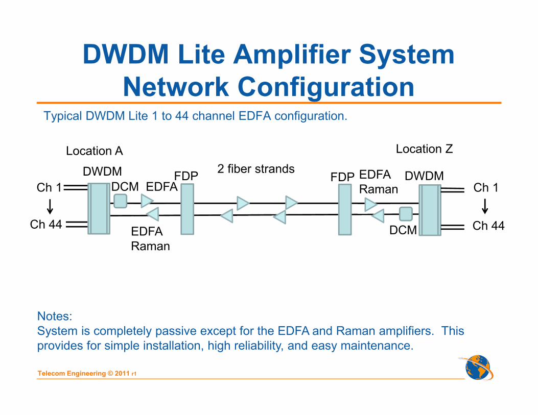
DWDM Lite Amplifier System
Network ConfigurationTypical DWDM Lite 1 to 44 channel EDFA configuration.
2 fiber strandsFDP FDP
Location A Location Z
DWDM DWDMCh 1
Ch 44
Ch 1
Ch 44
Notes:
System is completely passive except for the EDFA and Raman amplifiers. This
provides for simple installation, high reliability, and easy maintenance.
DCM EDFAEDFA
Raman
DCMEDFA
Raman

Telecom Engineering © 2011 r1
DWDM Lite Amplifier System
DWDM CCM MultiplexerDWDM CCM Multiplexer is available as a 8, 16, 32, 40 or 44 channel system.
Notes:
Our DWDM CCM multiplexers are specially designed to allow for simple individual
channel power adjustment, EDFA channel leveling and channel power / OSNR
monitoring. No special equipment required.
2 fiber strandsFDP FDP
Location A Location Z
DWDM DWDMCh 1
Ch 44
Ch 1
Ch 44
DCM EDFAEDFA
Raman
DCMEDFA
Raman

Telecom Engineering © 2011 r1
DWDM Lite Amplifier System
Dispersion CompensationCompensates fiber chromatic dispersion for long distance transmission, typically
used for greater than 80 km spans.
2 fiber strandsFDP FDP
Location A Location Z
DWDM DWDMCh 1
Ch 44
Ch 1
Ch 44
Notes:
Unit is completely passive, no configuration or adjustment required. Various fiber
compensation lengths available.
DCM EDFAEDFA
Raman
DCMEDFA
Raman

Telecom Engineering © 2011 r1
DWDM Lite Amplifier System
EDFAThe EDFA amplifier is used to amplify all signals in C-Band (DWDM) to compensate
for optical span loss. It is available as a booster, inline or preamp. It cannot be used
to amplify CWDM signals because of the very wide CWDM band.
2 fiber strandsFDP FDP
Location A Location Z
DWDM DWDMCh 1
Ch 44
Ch 1
Ch 44
Notes:
Remote and local access are available by Ethernet connection and standard SNMP
application. Hardened units to -25C and IEEE1613 are also available.
DCM EDFAEDFA
Raman
DCMEDFA
Raman

Telecom Engineering © 2011 r1
DWDM Lite Amplifier System
EDFA
Notes:
.

Telecom Engineering © 2011 r1
DWDM Lite Amplifier System
RamanRaman amplifiers are deployed in spans where EDFA deployment would result in
link OSNR to be lower than transceiver specification limit.
2 fiber strandsFDP FDP
Location A Location Z
DWDM DWDMCh 1
Ch 44
Ch 1
Ch 44
Notes:
Remote and local access by Ethernet connection. Gain of 10 dB.
DCM EDFAEDFA /
Raman
DCMEqualizer Equalizer
EDFA /
Raman

Telecom Engineering © 2011 r1
DWDM Lite Transponder
Channel tunable self contained transponder that converts 1310nm or 1550nm 10G
signals to DWDM channels with 100GHz or 50GHz channel spacing, tunable over 45
or 88 channels.
2 fiber strandsFDP FDP
Location A Location Z
DWDM DWDM
Ch 1 to
Ch 44
Ch 1 to
Ch 44
Notes:
Can be installed in CO or customer premise, built in dual 48Vdc power or 120/240Vac
power. Large optic budget, 30 or 35 dB without FEC, larger budget available with FEC.
Transparent to all 10G protocols including 10GE, SONET/SDH, OTN FEC
Full 3R signal regeneration. Adjustable DWDM output laser power +4 to +6 dBm.
DCM EDFAEDFA /
Raman
DCMEDFA /
Raman
1310 1310

Telecom Engineering © 2011 r1
DWDM Lite Transponder
Notes:
Telecom Engineering © 2011 r1
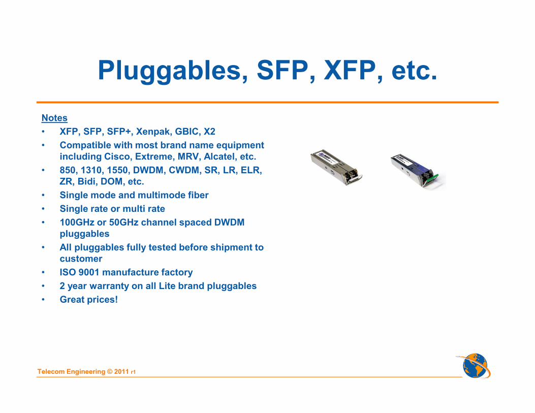
Pluggables, SFP, XFP, etc.
Notes
• XFP, SFP, SFP+, Xenpak, GBIC, X2
• Compatible with most brand name equipment
including Cisco, Extreme, MRV, Alcatel, etc.
• 850, 1310, 1550, DWDM, CWDM, SR, LR, ELR,
ZR, Bidi, DOM, etc.
• Single mode and multimode fiber
• Single rate or multi rate
• 100GHz or 50GHz channel spaced DWDM
pluggables
• All pluggables fully tested before shipment to
customer
• ISO 9001 manufacture factory
• 2 year warranty on all Lite brand pluggables
• Great prices!

Telecom Engineering © 2011 r1
Optical Amplifier Protection Switch
• 1:2 Protection for Optical
Amplifiers
• Protocol and rate independent
• Protects all DWDM wavelengths in
fiber in the event of an optical
amplifier failure
Optical Amplifier Protection Switch
Tx
Rx
Rx
Tx
EDFA 1
EDFA 2
EDFA Protection
TIP Optical Amplifier
Protection Switch
TIP Optical Amplifier
Protection Switch

Telecom Engineering © 2011 r1
Telecom Team
Bob Chomycz is the President of Telecom Engineering, Inc., and
Telecom Engineering USA, Inc. He is responsible for company
strategic engineering and operations.
Bob has over 24 years of engineering and management
experience in the telecom industry, ranging from detailed
engineering to management and team leadership. He has a
broad range of industry experience spanning telephone, cable
TV, electric utility and transportation industries. His engineering
designs include fiber optic, SONET, DWDM, EDFA, wireless, and
copper networks.
He is the author of three telecom books, “Planning Fiber Optic
Networks”, “Fiber Optic Installations: A Practical Guide” and
“Fiber Optic Installers Field Manual”.
Bob Chomycz, B.Eng. P. Eng.President and Founder

Telecom Engineering © 2011 r1
Telecom Team
Daniel S. Guay is the Network Operations Manager at Telecom
Engineering, Inc. He is responsible for company network
documentation, operations and support.
Daniel has been with Telecom Engineering, Inc. for 9 years and
is very knowledgeable with network designs and support.
As well, Daniel designs, installs, provisions, and tests
customer premise wired and wireless Local Area Networks.
Daniel S. Guay, CDNetwork Operations Manager

Telecom Engineering © 2011 r1
Telecom Team
Michael Tate, B.Sci.Telecom Engineer
Michael Tate is responsible for engineering and coordinating
projects from initial customer request to final installation. He
also heads up Research and Development for Telecom
Engineering USA.
Michael has been with Telecom Engineering USA for 4 years
and is knowledgeable in fiber optic design, installation, and
troubleshooting.
He has also headed up research leading to the application for
three separate patents in his time with Telecom Engineering
USA.

Telecom Engineering © 2011 r1
Equipment Testing Service
To ensure network equipment installation quality meets industry standards and customer requirements (SLA).
Services include:
• Bit Error Rate Test (BER)
• Data latency measurement
• Voltage and DC power measurements
• Equipment redundancy check
• DWDM network equalization report
• Network monitoring and alarms verification
• Wireless propagation tests and interference studies

Telecom Engineering © 2011 r1
Fiber Characterization Service
of Dark or Lit Fibers
Fiber characterization service provides detail fiber span parameter information
important for fiber network planning, records and SLA. If fiber is lit measurements
are taken during a maintenance window.
Report includes:
- OTDR traces to identify anomalies, poor splices, connector loss,
bad cable bends, fiber attenuation, reflectance, fiber length
- Power meter measurement at 1310, 1550 and 1611nm for span loss
(all CWDM channel measurement also available)
- Chromatic dispersion (CD) measurement, for proper compensation
- Polarization mode dispersion (PMD) measurement, for 10Gbps+ links
- Fiber latency measurement, for SLA
- Fiber / connector optical return loss (ORL) measurement
- Connector visual inspection with fiber scope and photos identifying
damaged connectors

Telecom Engineering © 2011 r1
Documentation Services
Telecom Engineering takes pride in providing detailed telecom network documentation .
Documents ensure that the design and management of any project is communicated clearly and accurately to all parties involved.
Project documents include:
• For Construction and As Built drawings, Color Coded, 11x17 inch size
• Project Description
• Project Schedule
• Circuit Roll & Implementation Plan
• Project Inventory Equipment / Material List,
• Detailed Project Cost Accounting Spread Sheet
• Network Testing Verification Reports,
• Customer Acceptance Certificate
Our staff is well versed in various software applications:
• Microsoft Suite (Word, Excel, PowerPoint, Access, Project)
• AutoCAD
• Adobe Publishing Suite
• Simply Accounting
As-Built Network Schematic
As-Built System Schematic

Telecom Engineering © 2011 r1
Documentation Services
We offer daily, weekly, and monthly status reports via email.
Documentation packages are vital in the design and installation process. We provide:
• Detailed network drawings
• Detailed system schematics (includes network elements and cabling identification)
• Telecom equipment room layouts
• Equipment rack layouts
Our documentation has proved its worthiness countless times during network troubleshooting, and scheduled maintenances.
As-Built Equipment Rack

Telecom Engineering © 2011 r1
Technical Support Services
Services:
• Complete fiber optic link “Turn-key” engineering, installation, provisioning, and
testing services
• Personnel training
• 24/7 network monitoring
• 24/7 telephone support, pre and post installation
• Dispatch technician/engineer for on-site maintenance service

Office Locations
Phone: 1-807-683-1770
Toll Free: 1-888-250-1562
Fax: 1-807-344-6968
Email: [email protected]
Website: http://www.TelecomEngineering.com
Minnetonka, Minnesota
Thunder Bay, Ontario


