75
Power Factor & Harmonics: StacoSine: Technical
| Date post: | 29-Jan-2018 |
| Category: |
Business |
| Upload: | staco-energy |
| View: | 129 times |
| Download: | 1 times |

Power Factor & Harmonics: StacoSine: Technical
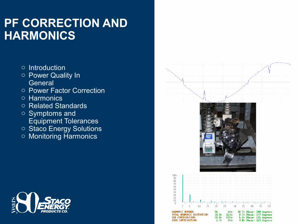
PF CORRECTION AND HARMONICS
o Introductiono Power Quality In
Generalo Power Factor Correctiono Harmonicso Related Standardso Symptoms and
Equipment Toleranceso Staco Energy Solutionso Monitoring Harmonics

THE IMPACT OF POWER PROBLEMS
o UPS Aloneo UPS & MBPS
2 Piece Shipping Splito Ambidextrous Side Caro Standard Kick Plateso Easy Transport & Installationo Single Hole or NEMA 2 Hole Landingo Standard UVR For Battery Cabinet
Can Be Configured For Shunt Trip
o $120-$180 Billion/yr. = cost of power outages and disturbances in U.S. economy 1
o 8 hrs, 45 minutes/yr. = typical utility grid downtime (99.9% reliability) in U.S.1
o $41,000/hour = cost of downtime, cellular communications 2
o $100,000/minute = lost sales, datacom/networking end user 3 o $8,000 = cost of voltage sag event -- average for all business 5
o $11,000 = cost of momentary outage event -- average for all business 5
o 30% of equipment insurance claims are due to electrical problems 6
o 68% of plant engineers and specifier’s state that “solving P.Q. issues is a very important challenge” 7
1 - EPRI -- Primen Study: The cost of Power Disturbances to Industrial and Digital Economy Companies
2 - 2001 U.S. DOE Distributed Energy Resource Program and Strategic Plan3- Venture Development Corporation Survey
4 - Energy Conservation News5 - 1996 Duke Power Survey6 - Hartford Steam Boiler 7 - EC&M Survey

THE CAUSES OF POWER PROBLEMS
o UPS Aloneo UPS & MBPS
2 Piece Shipping Splito Ambidextrous Side Caro Standard Kick Plateso Easy Transport & Installationo Single Hole or NEMA 2 Hole Landingo Standard UVR For Battery Cabinet
Can Be Configured For Shunt Trip
From Outside the Facility: Environmental problems affecting grid
reliability -- e.g., lightning, weather extremes, animal intrusion, resulting in:
Electrical outages, disruptionsVoltage sags and surgesTransients and overvoltagesFrequency or Harmonic problems
Operational Issues, including de-regulation, affecting grid reliability:
Reduction in MaintenanceAging Transmission SystemDemand / Supply (e.g. Calif..)Consolidations / MergersFinancial Concerns
From within the Facility: Aging building infrastructure or
equipment Building not designed for electronic
loads New equipment and processes do
not include mitigation solutions Improper wiring and grounding Outdated electrical system Equipment failures Improper maintenance Overloaded circuits Non-coordinated circuit protection
and/or electrical loads

POWER QUALITY PYRAMID™
o UPS Aloneo UPS & MBPS
2 Piece Shipping Splito Ambidextrous Side Caro Standard Kick Plateso Easy Transport & Installationo Single Hole or NEMA 2 Hole Landingo Standard UVR For Battery Cabinet
Can Be Configured For Shunt Trip
Relative CostHigh $/kVA
Low $/kVA The P.Q. Pyramid: Start with Grounding; add
other mitigating products where required
Outages (UPS; ATS; Flywheel; Gen)
Harmonic Distortion (Active/Passive Filters; K-Factor, Phase Shifting)
Voltage Variations (Tap Changer, Sag Correction, Ferro’s, DVR)
TVSS/PFC (AC,DC,Dataline)
Grounding/Bonding (ground rods, fittings, lightning system)

P.Q. SOLUTIONS ARE OFTEN CUSTOM: COST VARY LOCATION AND/OR INDUSTRY
o UPS Aloneo UPS & MBPS
2 Piece Shipping Splito Ambidextrous Side Caro Standard Kick Plateso Easy Transport & Installationo Single Hole or NEMA 2 Hole Landingo Standard UVR For Battery Cabinet
Can Be Configured For Shunt Trip
Manufacturing Facility (Medium Sized 480 V, 1000A)(eg. Plastics, Automation, or Higher Tech Assembly)
Capital ($ 000's)
Possible P.Q. SolutionSimple
SolutionMed Complex
SolutionP.Q. Survey = $0 $2 $15Grounding equipment = $0 $1 $5Lightning System = $0 $0 $20Surge Protection (hardwire, datacom) = $0 $5 $20
Surge Strips = $1 $1 $2Voltage Regulation/Sag Correction = $0 $0 $60
UPS (servers, telcom system, other small boxes) =
$4 $8 $12
Harmonics (reactors, capacitors, )= $0 $1 $20Ferroresonant or other power conditioners =
$2 $4 $6
Power Quality Monitor = $0 $1 $10Total $6.8 $21.4 $170.0
Does not include installation or ongoing maintenance
Other potential equipment: PDU, shielded isolation transformers,
parallel gear, generators, ATS

WHAT IS POWER FACTOR?
"Power factor" involves a relationship between two types of power: Working or Real
Power and Reactive Power. oWorking Power, which
performs the actual work of creating heat, light, motion, etc.
oReactive Power, which sustains the electromagnetic field.
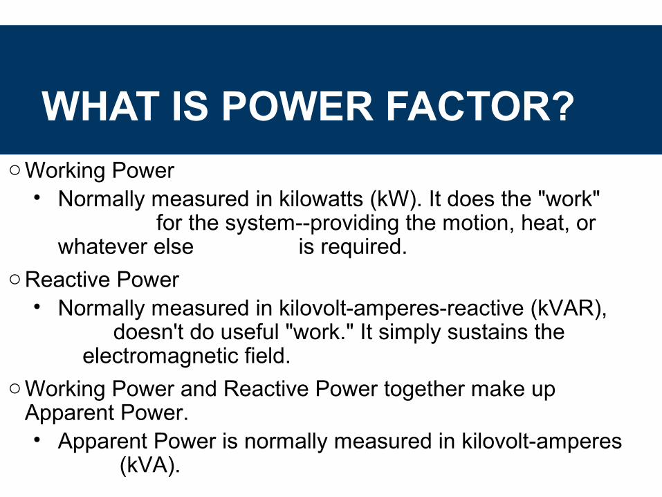
WHAT IS POWER FACTOR?oWorking Power
• Normally measured in kilowatts (kW). It does the "work" for the system--providing the motion, heat, or whatever else is required.
oReactive Power• Normally measured in kilovolt-amperes-reactive (kVAR),
doesn't do useful "work." It simply sustains the electromagnetic field.
oWorking Power and Reactive Power together make up Apparent Power. • Apparent Power is normally measured in kilovolt-amperes
(kVA).

WHAT IS POWER FACTOR?
oPower Factor is the ratio of Working Power to Apparent Power, or kW/kVA.
oPower Factor = Working Power / Apparent Power
PF = Cos Θ = kW / kVA
Θ
kW
kVA

APPARENT & DISPLACEMENT PF
oCalculation of displacement power factor:
• PF displacement = WATT/
[WATT2 + VAR2]. • Only the 60 Hz
components are measured.
• For use in power factor correction calculations.
oCalculation of apparent power factor:
• PF apparent = WATT/VA.
• This includes all measured harmonics.

WHAT DOES POWER FACTOR MEASURE?
oPower factor measures how effectively electrical power is being used. • A power factor reading close to 1.0 means that electrical power is
being utilized effectively, while a low power factor indicates poor utilization of electrical power.
oExample:• If you had a paper mill that was operating at 100 kW and the
Apparent Power consumed was 125 kVA, what is the Power Factor?
• This represents a fairly normal Power Factor. PF = 100 kW / 125 kVA
PF = 0.80

IS LOW POWER FACTOR A PROBLEM?oLow power factor means you're not fully utilizing
the electrical power you're paying for.
oIn the earlier example, with a Power Factor of 0.80
or 80%, your paper mill would be utilizing only 80% of the energy supplied by the utility. That means only 80% of the incoming current is being used to produce useful work.
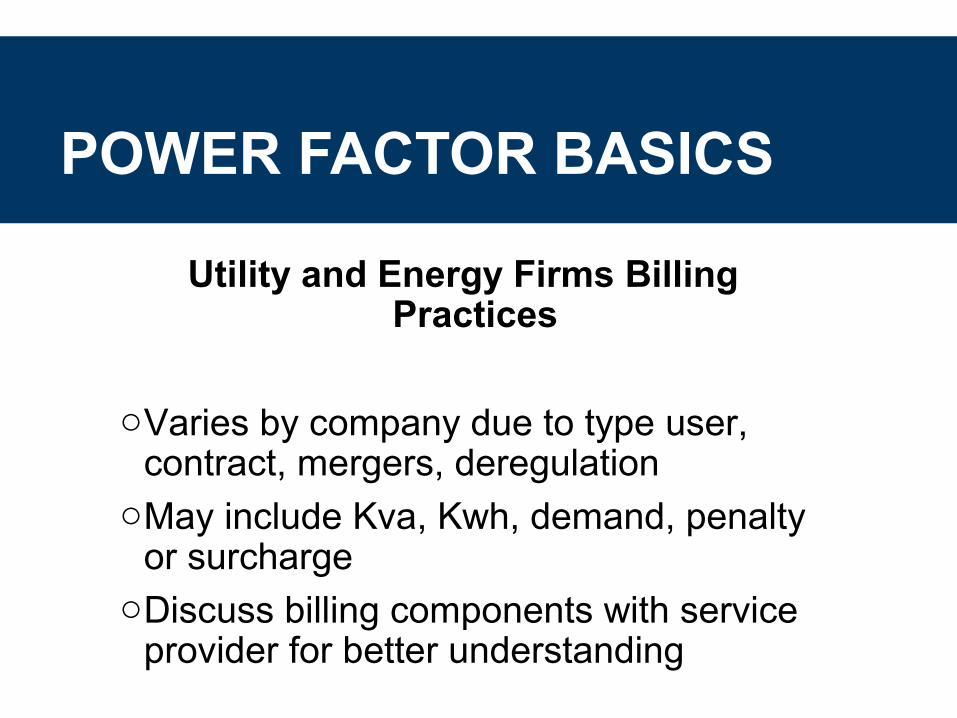
POWER FACTOR BASICS
Utility and Energy Firms Billing Practices
oVaries by company due to type user, contract, mergers, deregulation
oMay include Kva, Kwh, demand, penalty or surcharge
oDiscuss billing components with service provider for better understanding

TYPICAL ENERGY BILLCustomer:Customer: AnyAny Payment To:Payment To: Large Power Co.Large Power Co.Billing Period From:Billing Period From: 9/1/01 12:00:01 AM9/1/01 12:00:01 AM To:To: 9/30/01 12 Midnight 9/30/01 12 Midnight
Demand (Power) Demand (Power) Rate PeriodRate Period Peak atPeak at kVAkVA $/kVA $/kVA ChargeCharge
Off PeakOff Peak 10:35 PM10:35 PM 1,4871,487 3.253.25 $4,832.75$4,832.75On PeakOn Peak 1:05 PM1:05 PM 2,4962,496 16.7516.75 $41,808.00$41,808.00
EnergyEnergy kW hrkW hr $ / kW$ / kW.hrhrOff PeakOff Peak 224,600224,600 0.03690.0369 $8,287.74$8,287.74On PeakOn Peak 458,800458,800 0.0520.052 $23,857.60$23,857.60
Other Charges Other Charges Connection ChargeConnection Charge $500.00$500.00Power Factor Adj.Power Factor Adj. $390.00$390.00State Energy ChargeState Energy Charge 683,400683,400 -0.009-0.009 -$615.06-$615.06Taxes & Special ChargesTaxes & Special Charges $3,178.04$3,178.04
Total DueTotal Due $82,239.07$82,239.07

ENERGY MANAGEMENT
okW Hour (Usage - 1¢ - 15¢/kWH)okW Demand (15 Minute - $5 - $300/kW)oRatio of Usage to DemandokVAR (Power Factor) Penalties
ExamplePower Factor Penalty0.699 or lower Not permitted – 25%0.700 to 0.749 3%0.750 to 0.799 2%0.800 to 0.849 1%0.850 to 1.000 No penalty
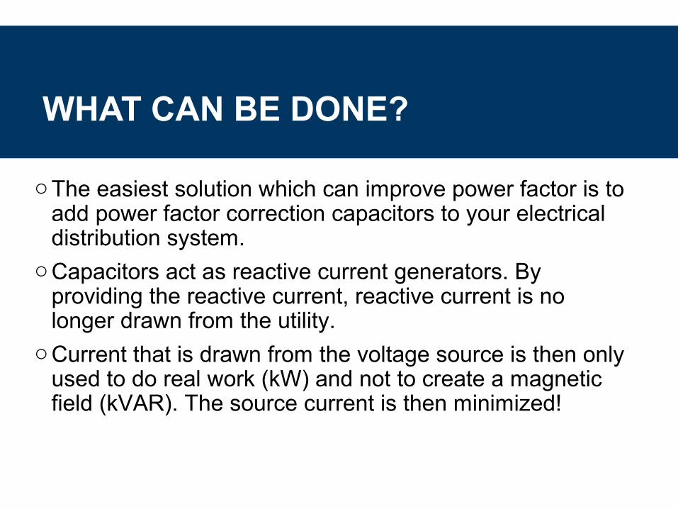
WHAT CAN BE DONE?
oThe easiest solution which can improve power factor is to add power factor correction capacitors to your electrical distribution system.
oCapacitors act as reactive current generators. By providing the reactive current, reactive current is no longer drawn from the utility.
oCurrent that is drawn from the voltage source is then only used to do real work (kW) and not to create a magnetic field (kVAR). The source current is then minimized!

WHY CONSIDER PF CORRECTION?
oPF capacitors provide many benefits:1. Reduced electric utility bills (a typical payback period is less than one year)2. Increased system capacity3. Improved voltage regulation4. Reduced heat losses in transformers & cables
oApplications that typically exhibit low Power Factors use motors and include:• air compressors• plastics extruders• machine tools• stamping• and others.

TYPICAL UNCORRECTED POWER FACTOR
By Industry PercentPower Factor
By Operation PercentPower Factor
Auto parts 75-80 Air compressor:Brewery 76-80 External motors 75-80Cement 80-85 Hermetic motors 50-80Chemical 65-75 Metal working:Coal mine 65-80 Arc welding 35-60Clothing 35-60 Arc welding with
standard capacitors
40-60
Electroplating 65-70 Resistance welding 40-60Foundry 75-80 Machining 40-65Forge 70-80 Melting:Hospital 75-80 Arc furnace 75-90Machine manufacturing 60-65 Inductance furnace
60Hz100
Metalworking 65-70 Stamping:Office building 80-90 Standard speed 60-70Oil-field pumping 40-60 High speed 45-60Paint manufacturing 55-65 Spraying 60-65Plastic 75-80 Weaving:Stamping 60-70 Individual drive 60Steelworks 65-80 Multiple drive 70Textile 65-75 Brind 70-75Tool, die, jig 60-65

APPLYING PF CAPACITORS
oSome factors that should be considered when applying PF capacitors:
• Where to apply?• Low voltage or medium voltage?• Fixed vs. Switched?

APPLYING PF CAPACITORS
oWhere to apply?• When applied close to the load (i.e. motor)
transformer and cable losses are reduced.• Lower installation cost when applied in a
central location.• Commonly applied at the utility metering
point.

APPLYING PF CAPACITORS
oLow voltage or medium voltage?• When applied on the 480V side of a substation
transformer and cable losses are reduced.• This may required multiple banks.• When utility feed is medium voltage a single bank at
PCC is often lowest cost.• Must first determine all the reasons for installing PF
capacitors:• Only to reduce utility bill?• Reduce load on cables and transformers?

APPLYING PF CAPACITORS
oFixed vs. Switched?• Fixed banks are simplest and lowest cost but can cause
problems:• Leading PF - some utilities charge• Overvoltage conditions when load drops
• If the plant load is fairly constant a fixed bank may work.• Usually a combination of some amount of fixed capacitance
and switched steps works best.• Also need to consider # of steps.

HARMONIC DISTORTION
oHarmonic problems are becoming more apparent because more equipment that produce harmonics
are being applied to power systems Harmonic
Solutions

SOURCES
General categories of nonlinear loads are:o Power Electronic Equipmento Arcing Deviceso Iron Saturating Deviceso Rotating Machines
SYMPTOMS
oTransformer heatingoMotor and generator heating
and vibrationsoNeutral heatingoNuisance fuse operationso Insulation deteriorationoElectronic control malfunctioningo Inconsistent meter readingsoVoltage regulator misoperations

HARMONICS BASICS
Harmonics and PFCoCapacitors do not create harmonicsoConcern for resonance – currents
amplified, voltage distortion, potential damage to capacitors
oReactors help to “de-tune” to below a certain order, balancing the capacitive requirement

HARMONICS APPLICATION REVIEW
oFacility walk-through – installed equipment, systems and processes
oReview plant electrical documentsoNote plans for new equipment,
expansionoAnalyze 6-12 months of electric billsoReview past electrical system studies,
may require a PQ survey, energy audit

HARMONICS APPLICATION REVIEW
oNote equipment most vulnerable to harmonics
oAny critical loads and process requiring “premium power”, outage concerns?
oReview downtime, scrap, maintenance, equipment replacement costs, loss of production, profits
oIsolated solution, long term PQ strategy

HARMONIC BASICS
Where Harmonics Exist
oWater treatment, glass making, steel processing, packaging, data centers, printing/publishing, paper processing, plastics, chemicals, automotive, to name few

HARMONIC BASICS
Economic Considerations
o Harmonics can create nuisance problems (rebooting a PC, restarting equipment) to serious concerns (product quality issues), through catastrophic events (production halted)…….monies lost

HARMONIC BASICS
oNew and replacement equipment/controls and devices typically are electronic, which may exacerbate a border-line harmonic condition, immediately creating a new set of problems, which ultimately affect business…….monies lost
oPartial “fixes”, lack to review total PQ situation……..monies lost

HARMONIC BASICS
SuggestionsoKeep a record of problems and
associated costsoActions taken to review and “fix”
problem(s), associated costsoPotential need to monitor (collect data)
on facility loads, to help with evaluationoDiscuss problem with a “solutions
driven” equipment manufacturer

HARMONICS & CAPACITORS
oCapacitors not only supply reactive power to the loads in an electrical distribution system they also change the resonance frequency of the system.
oCapacitors are also a “sink” for harmonic currents present in a system.
oWhen the resonance frequency of a system with PF correction capacitors is close to the frequency of a harmonic current generating load parallel resonance can occur.

HARMONIC DISTORTION
480 V
Xs
M
XT
G

HARMONIC DISTORTION
480 V
Xs
M
XT
UPSElectronic Ballast
+ -M
Blocking Filter
G
Welder

HARMONICS 100%, 60 Hz
2%, 780 Hz
20%, 180 Hz
12%, 300 Hz
4%, 420 Hz
2%, 660 Hz
%100...
%1
24
23
22 ×
+++=
I
IIITHDI

HARMONIC DISTORTION STANDARDSHarmonic Voltage Distortion LimitsIEEE Standard 519 – 1992
Maximum Voltage Distortion in % at PCC*
Below 69kV 69-138kV >138kV
Maximum for Individual Harmonic 3.0 1.5 1.0
Total Harmonic Distortion (THD) 5.0 2.5 1.5
* % of Nominal Fundamental Frequency Voltage

HARMONIC DISTORTION STANDARDS
Harmonic Order (Odd Harmonics)
Isc/IL <11 11<h<17 17<h<23 23<h<35 35<h %TDD
Maximum Harmonic Current DistortionIEEE Standard 519 – 1992
In Percent of Fundamental
<20* 4.0 2.0 1.5 0.6 0.3 5.0
20-50 7.0 3.5 2.5 1.0 0.5 8.0
50-100 10.0 4.5 4.0 1.5 0.7 12.0
100-1000 12.0 5.5 5.0 2.0 1.0 15.0
>1000 15.0 7.0 6.0 2.5 1.4 20.0

EXPECTED HARMONICS
H = NP+/-1
i.e. 6 Pulse Drive - 5, 7, 11, 13, 17, 19,…
Source Typical Harmonics*6 Pulse Drive/Rectifier 5, 7, 11, 13, 17, 19…
12 Pulse Drive /Rectifier 11, 13, 23, 25…
18 Pulse Drive 17, 19, 35, 37…
Switch Mode Power Supply 3, 5, 7, 9, 11, 13…
Florescent Lights 3, 5, 7, 9, 11, 13…
Arcing Devices 2, 3, 4, 5, 7...
Transformer 2, 3, 4
* Generally, magnitude decreases as harmonic order increases

VOLTAGE NOTCHING
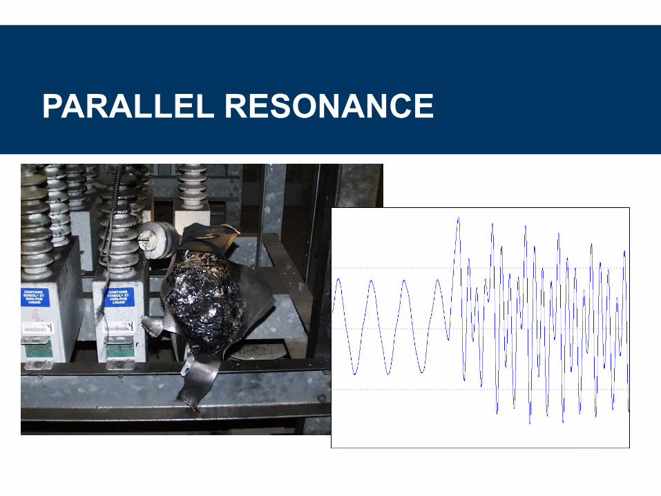
PARALLEL RESONANCE

PARALLEL RESONANCE
CAP
SCR MVAR
MVAf =
600 kVAR
1500 kVA5.0%
480 V
Xs
200 HPVSD
500 HP

MOTOR HEATING AND VIBRATIONS
60 Hz Rotation
5th Harmonic Rotation

NEUTRAL HEATING
C
B
A
N0A at 60 Hz
10A at 60 Hz
10A at 60 Hz
10A at 60 Hz
30A at 180 Hz
10A at 180 Hz
10A at 180 Hz
10A at 180 Hz
HARMONIC SOLUTIONS
• Clean power drives (18 Pulse)
• Clean MCC’s• Active harmonic filters
• Passive harmonic filters
• Blocking filters (drives)• Blocking filters (3rds)
• Zero-sequence traps
• Delta/Wye transformers • Harmonic cancellation (phase shifting transformers)
• Isolation transformers
• Commutation reactors• 200% neutral conductors
• K-factor rated transformers

EFFECT OF DRIVE LINE REACTORS (IEEE519-1992)

PHASE SHIFTING - 12 PULSE

PHASE SHIFTING - 72 PULSE
230KV
69KV
0° -40° -20° -10° 10° -30° 5° -35° -15° -45° -25°
69KV
-5°
0° 0°

HARMONIC CORRECTION SELECTION FOR DRIVES IN MCC’S
Drive Quantity
5 10 15 2010 Hp
50 Hp
125 Hpand up
Parallel / Passive Filter (10-20% Distortion)
SeriesPassive Filter (8-12% Distortion*)
Active Correction (5-20% Distortion)
18 Pulse Drive (5% Distortion*) 30 Hp
* per Drive
Recommendation based on price and MCC integration
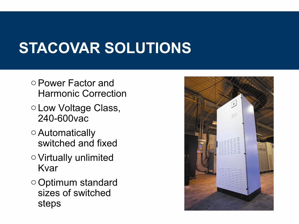
STACOVAR SOLUTIONS
oPower Factor and Harmonic Correction
oLow Voltage Class, 240-600vac
oAutomatically switched and fixed
oVirtually unlimited Kvar
oOptimum standard sizes of switched steps

STACOVAR SOLUTIONS
oSmall “footprint” with maximum KvaroStand-alone, multi-unit, integrated
systemsoModular design for expansion and
upgradeabilityoUL508A, complete assembly
STACOVAR SOLUTIONS
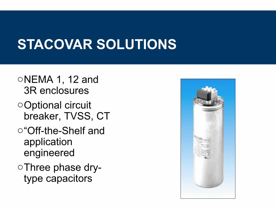
oNEMA 1, 12 and 3R enclosures
oOptional circuit breaker, TVSS, CT
o“Off-the-Shelf and application engineered
oThree phase dry-type capacitors

STACOVAR 100KVAR MODULE WITH CAPACITORS, REACTORS, CONTACTORS, FUSES

STACOVAR ZX AND ZXR APPLICATIONS
oPower systems with frequent load changes, voltage sags and surgesoWelding, flicker problemsoSaw mills, elevators, cranesoRolling mills, arc furnacesoEngine-generators, wind power
STACOVAR “TYPICAL” INTERNAL STRUCTURE ARRANGEMENT
Acrobat Document

STACOVAR “TYPICAL” ENCLOSURE ASSEMBLY
Acrobat Document
STACOVAR “TYPICAL” ENCLOSURE PLAN VIEW
Acrobat Document

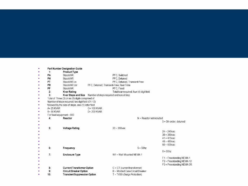
• STACO CATALOG NUMBERING SYSTEM
• To assist in the understanding of the Staco catalog numbering system, a brief explanation follows:
• Part Number Example
• P A - 0 0 7 5 – 0 1 A 0 1 B – N 4 8 6 W 1 – C B T
• ___ ______ ____________ __ __
• 1 2 3 4 5 6 7 8 9 10
• 1 PA= StacoVar Automatic Power Factor Correction
• 2 0075= 75kvar
• 3 01A= (1), 25kvar step 01B= (1), 50kvar step
• 4 N= No reactors
• 5 48= 480vac
• 6 6= 60hz
• 7 W1= Wall Mounted NEMA 1
• 8 C= Split Core CT- current transformer (option)
• 9 B= Molded Case Circuit Breaker (option)
• 10 T= TVSS –surge protection (option)

STACOVAR SOLUTIONS
Tuned Harmonic FiltersoApplication designed to trap or reduce problem harmonics
ACtive~trACoActive harmonic filters available early second quarter 2005
“At Load” Fixed CapacitorsoAvailable second quarter 2005
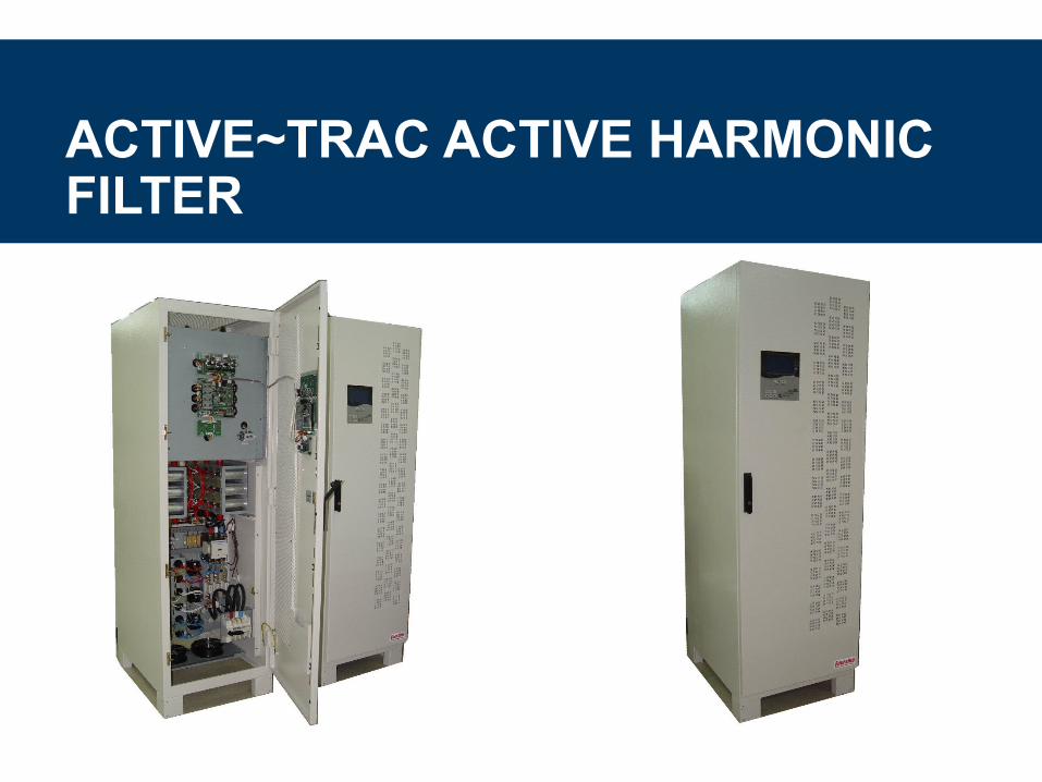
ACTIVE~TRAC ACTIVE HARMONIC FILTER
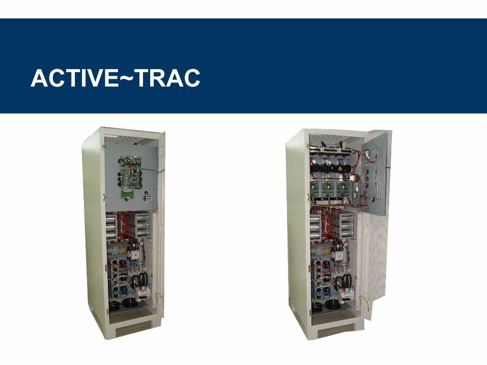
ACTIVE~TRAC
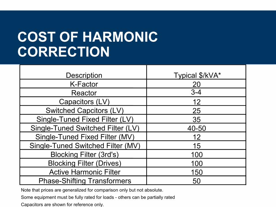
COST OF HARMONIC CORRECTION
Description Typical $/kVA*K-Factor 20Reactor 3-4
Capacitors (LV) 12Switched Capcitors (LV) 25
Single-Tuned Fixed Filter (LV) 35Single-Tuned Switched Filter (LV) 40-50
Single-Tuned Fixed Filter (MV) 12Single-Tuned Switched Filter (MV) 15
Blocking Filter (3rd's) 100Blocking Filter (Drives) 100Active Harmonic Filter 150
Phase-Shifting Transformers 50Note that prices are generalized for comparison only but not absolute.
Some equipment must be fully rated for loads - others can be partially rated
Capacitors are shown for reference only.

Special Considerations for Generators

NOTCHING AND GENERATORS
Generator Source may result in larger commutation notches and transients
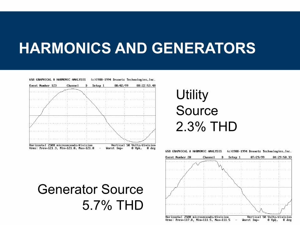
HARMONICS AND GENERATORS
Utility Source2.3% THD
Generator Source 5.7% THD

EXAMPLES OF PQ SITE SURVEYS
Oil Platform - Gulf of Mexico• The “Bad Noise” and the “Evil Noise”
Specialty Steel Tubing – Cleveland, OH• Newly installed PF Correction Capacitors Parallel
Resonant at 11th and 13th Harmonics
• Converted Capacitors to Filters
Nuclear Power Plant - Ohio• High Harmonic Distortion with Inverter
• Single Phase Harmonic Filters

EXAMPLES OF PQ SITE SURVEYS
Steel Mill - Pittsburgh, PA• Harmonic Resonance - Filter Failure
Data Center – Cleveland, OH• Harmonics Causing Nuisance Trips of Peak
Sensing Equipment
Video Reproduction Facility - Michigan• Transformer Overheating• Extremely High Harmonic Currents
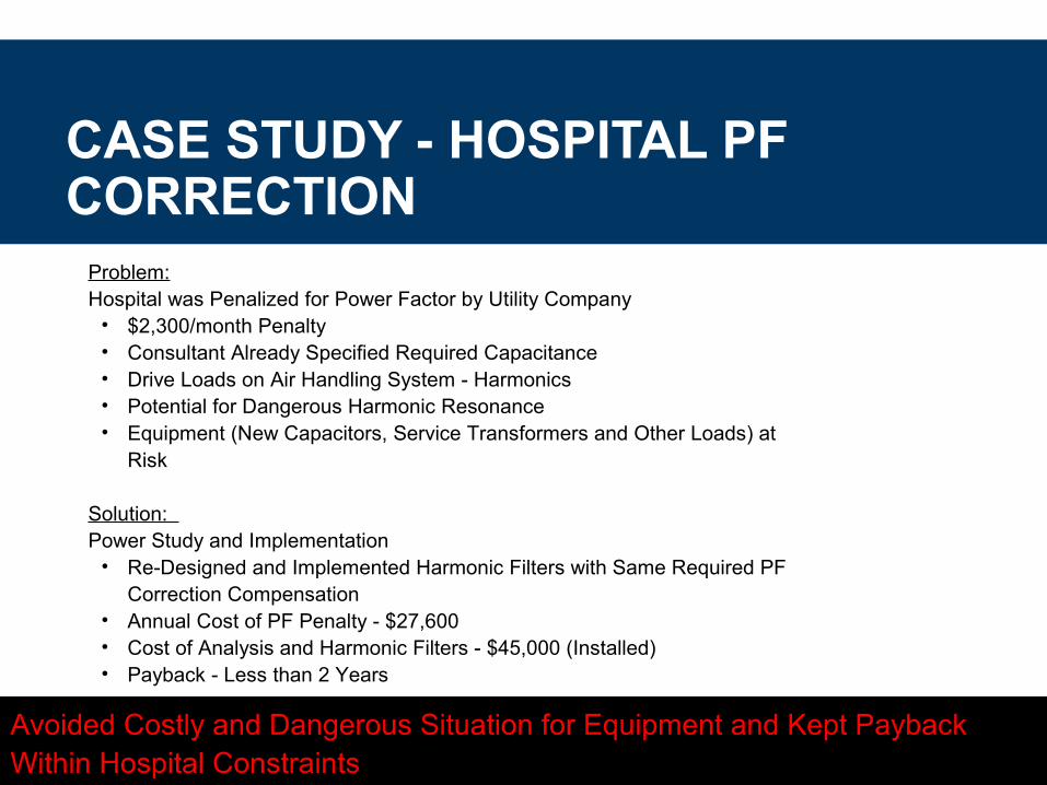
CASE STUDY - HOSPITAL PF CORRECTION
Problem: Hospital was Penalized for Power Factor by Utility Company
• $2,300/month Penalty• Consultant Already Specified Required Capacitance• Drive Loads on Air Handling System - Harmonics• Potential for Dangerous Harmonic Resonance• Equipment (New Capacitors, Service Transformers and Other Loads) at
Risk
Solution: Power Study and Implementation
• Re-Designed and Implemented Harmonic Filters with Same Required PF Correction Compensation
• Annual Cost of PF Penalty - $27,600• Cost of Analysis and Harmonic Filters - $45,000 (Installed)• Payback - Less than 2 Years
Avoided Costly and Dangerous Situation for Equipment and Kept Payback Within Hospital Constraints

CASE STUDY - PHASE SHIFTING
Solar Crystal R&DProblem: Harmonics from Multiple 15 kW DC Power Supplies
Harmonic Solution: New Facility Design with Phase Shifting (“Harmonic Cancellation”)
4160V
8x15KWFCE
480V 480V
etc.
12470V
480V480V

EXAMPLE - COMPUTER LOADS
Office Building o Problem: Cubicle Furniture “Smoking” as a Result of
Overheated Neutral (High 3rd Harmonics from Computer Loads)
o Solution: Run Separate Neutrals and Install K-Rated Transformers (“Live with Harmonics”)

CASE STUDY - NOTCHINGAutomotive Assembly• Problem: Large DC drives on Stamping Presses Caused
Voltage Notching on 4 kV Bus - Resulted in Incorrect Welding Timing - Recall on “Bad Welds”
Solution: Reduce or Eliminate Notching with Reactors/Filters or Phase Shifting Transformers
480V480V
12470V
4160V
StampingPresses
Welders

EXAMPLE - PQ SITE SURVEY
AF
National Lab - Linear Accelerator• Problem: Operation of Linear Accelerator Causes
Voltage Flicker and Significant Harmonics
Solution: Measurements and Specifications for Active Harmonic Filter Compensation
2MVA 2MVA 1.5MVA 1.5MVA
13.8KV
480V480V
AF

MONITORING HARMONICS
Snapshot - Continuous Loading
Long Term - Suspected Resonance or Significantly Varying Loads
Conditions
o All normal and contingent circuit configurations
o Each capacitor switching step if applicable
o For all characteristic representations of the speed or percent loading of the harmonic producing source(s)


