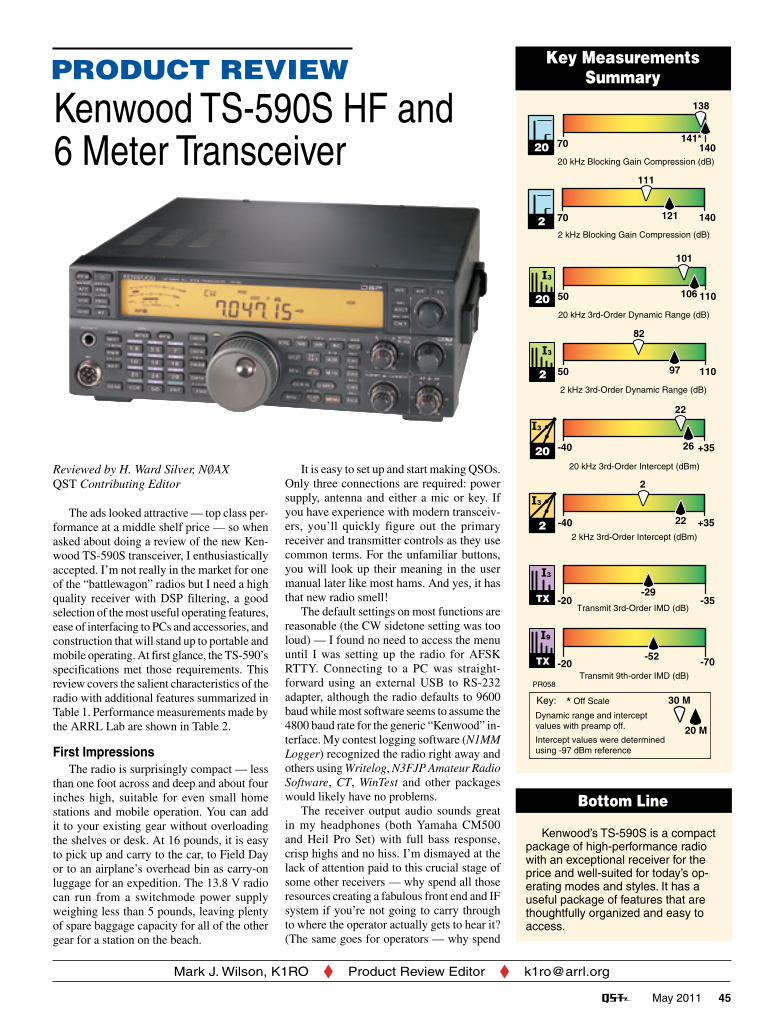
May 2011 45 PRODUCT REVIEW Mark J. Wilson, K1RO Product Review Editor [email protected]Key Measurements Summary Bottom Line Reviewed by H. Ward Silver, NØAX QST Contributing Editor The ads looked attractive — top class per- formance at a middle shelf price — so when asked about doing a review of the new Ken- wood TS-590S transceiver, I enthusiastically accepted. I’m not really in the market for one of the “battlewagon” radios but I need a high quality receiver with DSP filtering, a good selection of the most useful operating features, ease of interfacing to PCs and accessories, and construction that will stand up to portable and mobile operating. At first glance, the TS-590’s specifications met those requirements. This review covers the salient characteristics of the radio with additional features summarized in Table 1. Performance measurements made by the ARRL Lab are shown in Table 2. First Impressions The radio is surprisingly compact — less than one foot across and deep and about four inches high, suitable for even small home stations and mobile operation. You can add it to your existing gear without overloading the shelves or desk. At 16 pounds, it is easy to pick up and carry to the car, to Field Day or to an airplane’s overhead bin as carry-on luggage for an expedition. The 13.8 V radio can run from a switchmode power supply weighing less than 5 pounds, leaving plenty of spare baggage capacity for all of the other gear for a station on the beach. Kenwood TS-590S HF and 6 Meter Transceiver It is easy to set up and start making QSOs. Only three connections are required: power supply, antenna and either a mic or key. If you have experience with modern transceiv- ers, you’ll quickly figure out the primary receiver and transmitter controls as they use common terms. For the unfamiliar buttons, you will look up their meaning in the user manual later like most hams. And yes, it has that new radio smell! The default settings on most functions are reasonable (the CW sidetone setting was too loud) — I found no need to access the menu until I was setting up the radio for AFSK RTTY. Connecting to a PC was straight- forward using an external USB to RS-232 adapter, although the radio defaults to 9600 baud while most software seems to assume the 4800 baud rate for the generic “Kenwood” in- terface. My contest logging software (N1MM Logger) recognized the radio right away and others using Writelog, N3FJP Amateur Radio Software, CT, WinTest and other packages would likely have no problems. The receiver output audio sounds great in my headphones (both Yamaha CM500 and Heil Pro Set) with full bass response, crisp highs and no hiss. I’m dismayed at the lack of attention paid to this crucial stage of some other receivers — why spend all those resources creating a fabulous front end and IF system if you’re not going to carry through to where the operator actually gets to hear it? (The same goes for operators — why spend Kenwood’s TS-590S is a compact package of high-performance radio with an exceptional receiver for the price and well-suited for today’s op- erating modes and styles. It has a useful package of features that are thoughtfully organized and easy to access. PR058 30 M 20 M Dynamic range and intercept values with preamp off. Intercept values were determined using -97 dBm reference Key: * Off Scale -20 -70 ,TX Transmit 9th-order IMD (dB) -52 -20 -35 TX ,Transmit 3rd-Order IMD (dB) -29 -40 +35 ,2 2 kHz 3rd-Order Intercept (dBm) 22 2 -40 +35 ,20 20 kHz 3rd-Order Intercept (dBm) 26 22 50 110 ,2 2 kHz 3rd-Order Dynamic Range (dB) 97 82 50 110 ,20 106 101 20 kHz 3rd-Order Dynamic Range (dB) 70 140 121 111 2 kHz Blocking Gain Compression (dB) 2 70 140 141* 138 20 kHz Blocking Gain Compression (dB) 20
Reviewed by H. Ward Silver, NØAXQST Contributing Editor
The ads looked attractive — top class per-formance at a middle shelf price — so when asked about doing a review of the new Ken-wood TS-590S transceiver, I enthusiastically accepted. I’m not really in the market for one of the “battlewagon” radios but I need a high quality receiver with DSP filtering, a good selection of the most useful operating features, ease of interfacing to PCs and accessories, and construction that will stand up to portable and mobile operating. At first glance, the TS-590’s specifications met those requirements. This review covers the salient characteristics of the radio with additional features summarized in Table 1. Performance measurements made by the ARRL Lab are shown in Table 2.
First ImpressionsThe radio is surprisingly compact — less
than one foot across and deep and about four inches high, suitable for even small home stations and mobile operation. You can add it to your existing gear without overloading the shelves or desk. At 16 pounds, it is easy to pick up and carry to the car, to Field Day or to an airplane’s overhead bin as carry-on luggage for an expedition. The 13.8 V radio can run from a switchmode power supply weighing less than 5 pounds, leaving plenty of spare baggage capacity for all of the other gear for a station on the beach.
Kenwood TS-590S HF and 6 Meter Transceiver
It is easy to set up and start making QSOs. Only three connections are required: power supply, antenna and either a mic or key. If you have experience with modern transceiv-ers, you’ll quickly figure out the primary receiver and transmitter controls as they use common terms. For the unfamiliar buttons, you will look up their meaning in the user manual later like most hams. And yes, it has that new radio smell!
The default settings on most functions are reasonable (the CW sidetone setting was too loud) — I found no need to access the menu until I was setting up the radio for AFSK RTTY. Connecting to a PC was straight-forward using an external USB to RS-232 adapter, although the radio defaults to 9600 baud while most software seems to assume the 4800 baud rate for the generic “Kenwood” in-terface. My contest logging software (N1MM Logger) recognized the radio right away and others using Writelog, N3FJP Amateur Radio Software, CT, WinTest and other packages would likely have no problems.
The receiver output audio sounds great in my headphones (both Yamaha CM500 and Heil Pro Set) with full bass response, crisp highs and no hiss. I’m dismayed at the lack of attention paid to this crucial stage of some other receivers — why spend all those resources creating a fabulous front end and IF system if you’re not going to carry through to where the operator actually gets to hear it? (The same goes for operators — why spend
Kenwood’s TS-590S is a compact package of high-performance radio with an exceptional receiver for the price and well-suited for today’s op-erating modes and styles. It has a useful package of features that are thoughtfully organized and easy to access.
PR058
30 M
20 M
Dynamic range and interceptvalues with preamp off.
Intercept values were determinedusing -97 dBm reference
Key: * Off Scale
-20 -70TXTransmit 9th-order IMD (dB)
-52
-20 -35TXTransmit 3rd-Order IMD (dB)
-29
-40 +3522 kHz 3rd-Order Intercept (dBm)
22
2
-40 +352020 kHz 3rd-Order Intercept (dBm)
26
22
50 11022 kHz 3rd-Order Dynamic Range (dB)
97
82
50 11020 106
101
20 kHz 3rd-Order Dynamic Range (dB)
70 140121
111
2 kHz Blocking Gain Compression (dB)2
70 140141*
138
20 kHz Blocking Gain Compression (dB)
20
46 May 2011
Table 1TS-590S Miscellaneous Features
GeneralTCXO availableDirect frequency entryVariable tuning step rate with fine step setting110 memory channels with 8-character alphanumeric labelsQuick access memories (10 channels)Full scanning features (range or channels)CTCSS and subtone scanConfigurable for crossband repeater operation
Receive30 kHz – 60 MHz receiveSwitchable 12 dB or 20 dB preampSwitchable attenuator
Transmit60 meter band transmit enabledPaddle and key inputs, electronic keyerFour CW messages (no external control)Optional voice recorder and playback unit (VGS-1)RIT/XIT with clearTransmit monitorCW auto tuneEight character text tags for memories
Table 2Kenwood TS-590S, serial number B0900113Manufacturer’s Specifications Measured in the ARRL LabFrequency coverage: Receive, 0.03-60 MHz; Receive and transmit, as specified. transmit, 1.8-2, 3.5-4, 5.25-5.45, 7-7.3, 10.1-10.15, 14-14.35, 18.068-18.168, 21-21.45 21-21.44, 24.89-24.99, 28-29.7, 50-54 MHz.Power consumption at 13.8 V dc: receive, no Receive, no signal, default lights, 1.19 A; signal, <1.5 A; transmit (max), <20.5 A. receive, max volume and lights, 1.27 A, receive, no signal, no lights, 1.16 A; transmit 6.1 A at 5 W RF output, 15 A at 100 W RF output. Operation confirmed confirmed at 11.7 V dc (90 W output).Modes of operation: SSB, CW, AM, FM, FSK. As specified.
many hundreds of dollars on RF functions and then use cheap audio input and output gear?) Similarly, I got reports of “excellent” and “natural” audio on both the Kenwood hand microphone and the boom mics. Switching to the contest element for the Heil microphone resulted in reports of more punch to the audio. (Audio equalizer functions are available for both receive and transmit.)
Most of the front panel labels follow common standards or are sufficiently literal as to be obvious. Although the TS-590 is relatively compact, the controls are easy to use and reasonably grouped. I could easily use the radio either right or left handed and didn’t find myself making unintended changes from bumping too small or too close buttons. Although there are only six control knobs (the AF/RF GAIN, FILTER control, and NOTCH/SQUELCH controls are concentric) including the VFO, I did not find myself wishing for more. Most of the keys have a logical dual function, such as the VOX ON/OFF button that for “press and hold” brings up the VOX GAIN adjustment. In short, it was easy to use the radio effectively.
ReceiverThe radio’s top feature, undoubtedly, is the
receiver performance. As you can see from the ARRL Lab measurements table and the comparative indicators in the Key Measure-ments Summary, you get a lot of receiver per-formance for your dollar. In fact, if you check Sherwood Engineering’s ranking of receiver close spaced dynamic range (Rob Sherwood,
Second-order intercept point: Not specified. 14 MHz, Preamp off/on: +63/+63 dBm.FM two-tone, third-order IMD dynamic range: 20 kHz offset, Preamp on: 29 MHz, Not specified. 86 dB†; 52 MHz, 86 dB†. 10 MHz offset: 52 MHz, 100 dB.S-meter sensitivity: Not specified. S9 signal at 14.2 MHz, preamp off/on, 48.7/14.4 µV.Squelch sensitivity: 28-30 & 50-54 MHz FM, At threshold: 14 MHz SSB, 2 µV; <0.2 µV; at 14 MHz (SSB), <1.8 µV. FM (preamp on) 29 MHz, 0.08 µV; 52 MHz (preamp on), 0.12 µV.Receiver audio output: >1.5 W into 2 W at 10% THD into 8 W. 8 W at 10% THD. THD at 1 V RMS: 0.6%.DSP noise reduction: Not specified. NR1/NR2, 10/20 dB.Notch filter depth: Not specified. Manual notch: 51 dB, auto notch: 60 dB. Attack time: 180 ms.IF/audio response: Not specified. Range at –6 dB points, (bandwidth):‡ CW (500 Hz): 315-927 Hz (612 Hz) Equivalent Rectangular BW: 596 Hz USB: (2.4 kHz): 53-2253 Hz (2200 Hz) LSB: (2.4 kHz): 52-2252 Hz (2200 Hz) AM: (5 kHz): 147-2350 Hz (4406 Hz).IF rejection, >70 dB. First IF rejection, 14 MHz, 84 dB; 28 MHz, 100 dB; 50 MHz, 100 dB.Image rejection: >70 dB. Image rejection, 14 MHz, 91 dB; 28 MHz, 100 dB; 50 MHz, 92 dB.
Transmitter Transmitter Dynamic TestingPower output: 5-100 W, (5-25 W AM); CW, SSB, RTTY, FM, typ 4.8-99.0 W; AM, typ 4.8-25.5 W.Spurious-signal and harmonic suppression: Worst: 56 dBc, 1.8 MHz, 2nd harmonic. 1.8-29.7 MHz, >50 dB; 50-54 MHz, .60 dB. Meets FCC requirements.SSB carrier suppression: >50 dB. 55 dB.Undesired sideband suppression: >50 dB. 62 dB.Third-order intermodulation distortion (IMD) 3rd/5th/7th/9th order (worst on HF, 10 m): products: Not specified. HF, 100 W PEP, –29/–32/–42/–52 dB; 6 m, 100 W PEP, –34/ –34/–48/–56 dB.CW keyer speed range: Not specified. 4 to 55 WPM.CW keyer iambic keying mode: Not specified. A or B, menu selectableCW keying characteristics: Not specified. See Figures 2 and 3.Transmit-receive turnaround time (PTT S9 signal, AGC fast, 30 ms. release to 50% audio output): Not specified.Receive-transmit turnaround time (tx delay): SSB, 14 ms; FM, 14 ms. Not specified.Composite transmitted noise: Not specified. See Figure 1.Size (height, width, depth): 3.8 × 10.6 × 11.4 inches; weight, 16.3 lbs.Price: $1800
*The TS-590S operates as either a double down conversion receiver (RX1) or triple up conversion receiver (RX2) depending on the band of operation and filter bandwidth selected. See text for details. RX1 with 500 Hz roofing filter was used for receiver tests at 3.5 and 14 MHz; RX2 with 15 kHz 1st IF filter and 2.7 kHz 2nd IF filter was used for testing on other bands.**Exceeded figures indicated; test results shown measured with +10 dBm maximum output from test fixture.***ARRL Product Review testing now includes Two-Tone IMD results at several signal levels. Two-Tone, 3rd-Order Dynamic Range figures comparable to previous reviews are shown on the first line in each group. The “IP3” column is the calculated 3rd order intercept point. Second-order intercept points were determined using –97 dBm reference.†Measurement was noise-limited at the value indicated.‡Default values; bandwidth and cutoff frequencies are adjustable via DSP. CW bandwidth varies with PBT and pitch control settings. For SSB, DSP set to 2600 Hz for “high” and 200 Hz for for “low” for a width of 2400 Hz.
Frequency in kHz
fcfc-4 fc-2 fc+2 fc+4
Rep
onse
, dB
QS1105-ProdRev03
Figure 1 — Spectral display of the TS-590S transmitter output during composite noise testing. Power output is 100 W on the 14 MHz band. The carrier, off the left edge of the plot, is not shown. This plot shows composite transmitted noise 100 Hz to 1 MHz from the carrier. The reference level is 0 dBc, and the vertical scale is in dB.
Figure 2 — CW keying waveform for the TS-590S showing the first two dits in full-break-in (QSK) mode using external keying and default settings. Equivalent keying speed is 60 WPM. The upper trace is the actual key closure; the lower trace is the RF envelope. (Note that the first key closure starts at the left edge of the figure.) Horizontal divisions are 10 ms. The transceiver was being operated at 100 W output on the 14 MHz band.
Figure 3 — Spectral display of the TS-590S transmitter during keying sideband testing. Equivalent keying speed is 60 WPM using external keying. Spectrum analyzer resolution bandwidth is 10 Hz, and the sweep time is 30 seconds. The transmitter was being operated at 100 W PEP output on the 14 MHz band, and this plot shows the transmitter output ±5 kHz from the carrier. The reference level is 0 dBc, and the vertical scale is in dB.
48 May 2011
NCØB, www.sherweng.com/table.html), you’ll find the TS-590 coming in ninth. Also tenth — what the heck?
The TS-590 is a very interesting super hetero -dyne that operates as either a double-down conversion (RX1) or triple up-conversion (RX2) depending on the band and filter bandwidth. This allows the radio to balance sensitivity (higher for RX2) with selectivity (better for RX1). Both modes are quite good, as evidenced by the ninth and tenth place position in the Sherwood results. Moving over to Rob’s column of wide spaced dynamic range data you’ll find the receiver has top class numbers there. Strangely, aside from a single table entry, this important aspect of the radio’s operation is not mentioned at all in the owner’s manual!
The more selective RX1 is used on the 160, 80, 40, 20 and 15 meter bands when the IF bandwidth is 2.7 kHz or less for SSB, CW and FSK. The crowded, large signal segments of these traditional DXing and contesting bands are where receiver dynamic range is most important. Depending on the mode selected, a 2.7 kHz or 500 Hz roofing filter follows the first mixer at the 11.374 MHz first IF stage.
On other bands, including 10 meters, and for wider IF bandwidths such as for AM and FM, the more sensitive RX2 is used. A 15 kHz roofing filter is used at the 73 MHz first IF, followed by 15, 6 or 2.7 kHz filters at the 10.7 MHz second IF. (The transmitter chain always uses the up-conversion mode.)
The final IF for both RX1 and RX2 is at 24 kHz where sharper filtering is performed by a 32 bit floating point DSP. The IF is where the AGC system is implemented — an important part of the radio’s performance. I found the adjustable AGC action to be quite clean — no clicks, thumps or pops. It’s possible for a very close signal to be inside the roofing filter but outside a narrower DSP filter, causing the audio level to fall dramatically, but the signal has to be really close. I did not try the receiver on the receiving end of a big pileup (I offered to fly to the Caribbean for the ARRL DX CW contest, but no…) so I can’t speak to the radio’s ability to handle many signals inside the passband at once.
Another feature is the use of a direct digital synthesizer (DDS) instead of a phase locked loop (PLL) for the main VFO. Since lower noise sidebands are generated by the DDS VFO, less reciprocal mixing occurs with adjacent signals to raise the apparent receiver noise floor. Kenwood has managed to mini-mize the spurious products often associated with DDS signal sources, as well. One small spur was noted during ARRL Lab receiver blocking testing at a level so low as to be inaudible in actual use. Transmit composite noise as seen in Figure 1 is very low — better than some radios costing quite a bit more —
making your neighbors on the bands happy.For those of you who don’t chase DX or
enter contests, why do dynamic range and re-ciprocal mixing and transmitted noise matter during noncompetitive operation? The answer is that it matters any time there are strong signals on the bands. Being able to carry on a contact even next to a strong local signal or in the middle of a big contest makes a lot of difference in your ability to operate under any conditions. If you can acquire that capability without having to spend top dollar to get it, you’ve made a good purchasing decision.
All users will appreciate the adjustable noise blanker (NB) and noise reduction (NR) systems. NB1 is an analog noise blanker based on the output of the first roofing filter. NB2 is a digital noise blanker that uses signal envelopes. I found both to be effective on different types of noise and neither responded excessively to strong in-band signals as with most analog noise blankers. NR1 is optimized for use with SSB signals and NR2 for use with CW and data signals. I found both to be quite effective, particularly when trying to dig weak DX signals out of the various noises an urban residence inflicts on the amateur. When either NR system is turned up to its most aggressive setting audible artifacts are created (NR2 arti-facts sound like the band is “boiling”) but both are far better than the noise they have replaced. The four (NB1/NB2/NR1/NR2) adjustable noise fighters are a pretty powerful tool box for fighting atmospheric noise.
If you haven’t used good DSP IF filters, you are in for a treat. Response of the TS-590 filters is adjustable in steps — a little coarser than I would prefer, but perfectly adequate. Operation of the filter controls is linked to the mode in use. For SSB, AM and FM, filter adjustments are for the high and low cutoff frequencies. Using CW, FSK and data modes, the same controls adjust center frequency and bandwidth. This is a little odd but you get used to it right away. Two sets of filter settings can be stored as IF A and IF B, selectable by a front panel pushbutton, creating a pair of customizable narrow and wide filters. Along with the band pass filters there are a pair of filters that cancel steady tones plus manual and automatically tuned notch filters.
Basic Performance ElementsMechanically, the radio is solid and com-
pact. Built around a die cast frame, there are three PC boards: transmitter on top, receiver underneath and a front panel. Don’t tell the folks at HQ, but I gave the TS-590 a casual “thump” test, setting it down abruptly on all sides except the front panel — no problems resulted. Even while I was search and pounc-ing on RTTY, the fans rarely came on and were quiet when they did.
Transmit output is 5 to 100 W and set-
table on a band-by-band basis — useful on 10 and 6 meters for setting drive to amplifiers. The microphone circuits offer adjustable high/low response cut and a six setting audio equalizer. IMD performance is very clean as shown in the ARRL Lab Measurements table, especially for a 13.8 V radio. The REMOTE connector on the back panel provides a complete amplifier control interface.
Low band enthusiasts will be glad to hear that CW waveform is nicely controlled with adjustable rise times as shown in Figure 2. The keying sideband performance in Fig- ure 3 is really good — below –60 dBc at 1 kHz spacing. The radio features an internal antenna tuner with setting memories for 25 frequency ranges and that is specified to match up to SWR of 3:1. I found that it worked well with a nonresonant 105 foot doublet although at higher SWR my external tuner was needed. A separate receive antenna input is provided on the back panel. Trans-verter operation is supported by a 0 dBm (1 mW) output signal to extend coverage beyond 6 meters to the lower VHF and UHF bands. The radio’s display can be configured to display the transverted signal’s frequency, as well.
Another welcome feature is the USB serial data interface, in addition to the classic 9 pin RS-232 interface. Not only can you control the radio and use the USB interface for FSK data, you can also use the USB interface for send and receive audio. As with most USB implementations, however, the audio on the USB interface is delayed by many millisec-onds and that may be unsuitable for certain modes or types of operating. The delay was quite noticeable, but tolerable, especially dur-ing RTTY operation. Using the USB interface requires the installation of a virtual COM port driver and the ARUA-10 USB Audio Control-ler software, both available at no cost from Kenwood.
I urge all radio manufacturers to offer a USB interface as soon as practical along with standard USB class definitions and implementations. It is bad enough that mi-crophones aren’t interchangeable but having to manage incompatible proprietary drivers would be a huge problem for most users and create customer service headaches. Please — standardize!
The radio has a generally uncluttered display, quite visible at all angles. I liked the choice of variable brightness green or amber backlight. While filters are adjusted, a tem-porary value is displayed and for menu selec-tions, the scrolling labels long enough to be meaningful are a nice touch. Changing modes produces a Morse code annunciation, too.
There are two front panel programmable function keys (four on the optional MC-47 mi-
May 2011 49
crophone) including a tune function. As with nearly every radio sold today, configuration of many items is menu driven and the TS-590 has 88 settable parameters. The items are logically grouped and easy to access. You can save two full sets of parameters and there is a “quick menu” for commonly adjusted settings.
Contest and DXing PerformanceMy first experience with the TS-590 was
in the CW Sweepstakes from W1AW. Since the radio’s main performance selling point was its receiver you can be sure that I gave it every opportunity to fold under the onslaught of S9+++ signals but it did not complain. Even deliberately tuning close to strong signals, I detected not a single receiver generated arti-fact or product with the preamplifier and noise blanker turned off. The DSP filtering could make adjacent signals disappear in most cases.
The only problem I encountered was a sig-nificant power overshoot on the leading edge of a first dot or dash before recovering to the intended level. That caused the ACOM 2000 amplifier to trip offline unless we reduced drive, dropping amp output to 800-1000 W. The problem was eliminated by a firmware upgrade from Kenwood and verified by testing with the same amplifier at W1AW at the legal limit. (See PC Host Software and Firmware.)
The radio was shipped to my home station where I tested it further, albeit without an amplifier. I was consistently pleased with the radio’s performance on all bands. On SSB, using the Yamaha and Heil boom mics, audio reports were good, including contacts with the speech processing turned on. Note that it is possible to turn the compression up too far as on almost any radio, distorting your voice and making the power supply fan sound like a jet engine! The default microphone gain was a little high for competitive voice levels but no other adjustment was required for satisfac-tory reports.
On CW, I am pretty picky about not want-ing to hear any switching transients during full QSK (full break in keying) at high speeds above 30 WPM. Both semi and full break in were fine during the Thursday night sprints and other CW contests. The radio has an amplifier keying delay (menu items 53 and 54) that can cause “choppy” keying if acti-vated (default value is OFF) while operating in full QSK.
DXers will find TFSET to be a “why didn’t I have this before” feature. While operating split, it’s common to jump back and forth between the A and B VFOs to see what’s
happening on your transmit frequency, find a clear(er) spot in the pileup, or see who the DX is working. A common error in the heat of the moment is to forget to switch back or to press the A/B switch twice so that your call sign rings out loud and clear on the DX fre-quency (or worse, out of the US band) for all to hear (and comment upon). TFSET switches frequencies, too, but only until you take your finger off the button — it’s much harder to make a mistake that way.
The radio’s triple band stacking registers for search and pounce operating are very use-ful. It’s easy to tune up and down the band loading the registers, then hop back and forth between three pileups until you get through. It can more than double your search and pounce contact rate over just using one VFO.
Getting all the various connections and software actors configured properly for op-erating in the CQ WPX RTTY Contest was a bit of a challenge. The radio’s User Manual gives little guidance in the practical issues of getting the USB audio interface to work and I had to rely on third party websites — thank goodness for Google! Eventually, though, I was successful using MMTTY as my RTTY “engine” with audio connections to the radio over the USB interface, controlled by the TS-590 menu settings for DATA VOX and DATA GAIN, transmitting LSB AFSK. The radio’s DATA mode selection configured the DSP filters correctly for the mark and space frequencies. This was definitely not plug and play operation but I was successful in making RTTY contacts. The rear panel ACC2 con-nector has all the analog signals you need for audio based data operation.
On 6 meters in the January VHF Sweep-stakes, I made a limited number of contacts due to poor conditions but the radio was plenty sensitive and I received good audio reports on the band.
PC Host Software and FirmwareKenwood also provides free PC host soft-
ware — the Radio Control Program (ARCP-590) that provides a remote front panel and configuration of the radio, and the Network Command System (ARHP-590). See www.kenwood.com/i/products/info/amateur/software_download.html. VoIP software for voice over the remote link is available from third parties. I prefer to operate the radio directly but if you like using your PC, the software makes all controls easily available via the USB interface. You can also operate the radio from a VHF or UHF radio using
Kenwood Sky Command II remote control.The radio’s firmware (the internal micro-
processor’s program) can be upgraded by downloading a compressed file from Ken-wood’s website and using either the RS-232 or USB interface with your PC. A stand-alone control program then leads you through the steps to load the new firmware and reset the radio — that’s it! The ability to upgrade firm-ware in your shack will extend the useful life of the radio and allow Kenwood to provide better customer support without anyone hav-ing to ship radios back and forth. The review radio originally shipped with firmware rev 1.00 but was upgraded to firmware rev 1.02 for final testing.
What’s Not ThereThis is a mid range radio so you won’t find
high end features such as a spectrum scope or a second receiver. The roofing filter selection is fixed by mode but with the DSP filtering this isn’t a huge issue. It would have been nice to have separate control lines for indi-vidual HF and VHF amplifiers. FM repeater shift is accomplished by using dual VFOs in split mode. A USB memory stick interface for storing configurations or receive audio would be useful.
The ARRL Lab noted that 60 meter op-eration is not channelized. This rig transmits from 5.250 to 5.500 MHz on all modes. Other radios we have tested only operate USB on the five specific frequencies allocated for amateur use. It would be easy for an operator to operate on the wrong frequency or mode. We recommend that operators carefully pro-gram the 60 meter channels into memories to avoid accidentally transmitting on unallocated frequencies.
SummaryIn summary, I’d say this radio gives the
most bang for the buck I’ve seen in quite a while. Download the User’s Manual from the Kenwood website and explore on your own. The TS-590S would make a good home station or mobile radio. With transverters it could be the foundation of a 160 through 432 MHz station. (Higher UHF bands really need a 144 MHz IF for transverters to be ef-fective.) Stations using a top of the line radio would find the TS-590S a very cost effective second radio, as well.
Manufacturer: Kenwood USA Corp, 3975 Johns Creek Ct, Suite 300, Suwanee, GA 30024; tel 310-639-4200, fax 310-537-8235; www.kenwoodusa.com.
50 May 2011
MicrophoneBoomThe mic boom extends out from a
fixed position on the left headphone transducer through a short goose-neck. Earlier headset mics had a swiveling fixture that allowed the mic boom to be moved out of the way for listening without transmitting or for CW or digital mode operation.
I suspect that the new ar-rangement provides a more reliable mic connection ar-rangement, with less fatigue applied to the mic wires. The new arrangement has a shorter boom — ending up near the corner of the opera-tor’s mouth, with easy adjustment for vertical or horizontal position from there. It is far enough from “front and center” that it doesn’t take much change in position to have it out of the way and not be particularly noticeable — I was able to drink coffee, for example, without interference. This new arrangement seems to work well for me, and I wasn’t bothered by it during my mostly CW operations.
HeadphoneDesignThe headphones are also constructed dif-
ferently from previous models. Other Heil headsets that I have encountered — perhaps all, but certainly most — used a ball and socket arrangement to attach the headphone transducers to the headband. The Elite uses a new dual hinge and pivot arrangement. This is more typical of what has been found on other headsets. As can be seen in Figure 4, an upper in and out hinge joint is followed by a pivoting connection and then a fork that attaches to each transducer. Somehow they managed to thread the wire for the right hand transducer through all that so that it all comes out, with the mic wiring, as a single coiled cable on the left side. It all works for me.
In my earlier review of the Pro Set Plus, I noted that the long uncoiled cord kept get-ting tangled in the wheels of my desk chair. I definitely prefer the coiled cord. I’m sure
Reviewed by Joel R. Hallas, W1ZRQST Technical Editor
The new Heil Pro Set Elite headset is designed for either amateur or professional use. This Pro Set Elite represents a bit of a departure from recent Heil headsets in a num-ber of ways. First, both the headphones and microphone are designed for wide frequency response with a flat response characteristic across the band — unlike the tailored com-munications response of earlier headsets. Second, the mechanical design is different from earlier models.
TransducersThe Elite headset employs the new HC-6
microphone element that we discussed in the review of the Heil Quiet Pro headphones and MB-1 boom microphone.1 The HC-6’s flat microphone response — instead of the choices of HC-4 (the pileup buster) or HC-5 with highly articulated response for regular communications — is in recognition of the fact that many modern transceivers have built-in transmit audio equalizers that can be used to set the response characteristics the way operating conditions, and voice char-acteristics, require. Its specified response, –3 dB points at 100 Hz and 12.5 kHz, should support most applications with appropriate equalization. The Heil website offers a set of starting point settings for many popular radio equalizers with all of its current mic elements.
In a similar vein, the headphone transduc-ers are also full range “high fidelity” response type. Thus this headset can perform double duty as a stereo headset for music, if you wish. Again, for Amateur Radio or other commu-nications use, this will be most useful if the receiver, or receive equalizer, can limit audio response to communications bandwidths. Some older equipment can provide audio hiss above communications bandwidths and it’s better not to have to eliminate that with your gray matter. The Elite does continue to provide the popular phase reversal switch that can move the apparent sound source out from the middle of the operators head.
Mechanical ArrangementBoth the headphone and microphone me-
chanical designs are different from earlier Heil headsets, in ways that I found agreeable.2,3
Heil Pro Set Elite Headset
others prefer a non-coiled version — perhaps Heil will consider a version for those folk at some time in the future.
ConnectorArrangementsThe Elite comes equipped with a 3.5 mm
stereo plug for the stereo headsets and a 3.5 mm mono plug for the mic. Also pro-vided is a 3.5 mm to 1⁄4 inch stereo adapter to allow the phones to plug into the usual 1⁄4 inch front panel headphone jack. Heil offers their AD-1 series of adapter cables to match the miniature mic connector to the round or modular plugs used on the front panels of most radios. The adapter also includes a 1⁄4 inch socket intended for a foot or hand switch for transmit-receive (TR) control if VOX isn’t used.
Many will opt for the AD-1 adapters, but they are not needed for all radios. For example, my Elecraft K3 can accept the na-tive plugs into rear panel connectors, making for a neat arrangement. It also has a rear jack that can be used for a foot or hand TR switch. The length of the coil cord is really a better fit to front panel connections, but it worked satisfactorily for me using the rear connec-tion points.
Heil also offers a version for most modern ICOM radios, the Pro Set Elite iC. This uses a wide bandwidth electret mic element with similar response to the HC-6. The electret element requires +5 V dc bias, provided at the mic connector of ICOM radios. We did not test this model.
1J. Hallas, W1ZR, and N. Hallas, W1NCY, “A Look at Noise Canceling Headphones,” Product Review, QST, May 2010, pp 52-53.
2D. Patton, NN1N, “Heil Pro Set Quiet Phone Noise Canceling Headset,” Product Review, QST, Jun 2006, pp 71-72.
3J. Hallas, W1ZR, “Heil Pro-Set Plus Headset with Boom Microphone,” Product Review, QST, Dec 2003, pp 61-63.
Bottom Line
The Heil Pro Set Elite is a worthy addition to the popular Pro Set line of headsets. It offers comfortable wider range earphones, combined with a wide range high fidelity dynamic mic element. The mic element is intend-ed to be tailored by radio or external audio equalizers to provide just the desired voice characteristics.
May 2011 51
On the AirSince I am mostly a CW operator,
the use of the headphones without the mic is of significant importance to me. I found the headphones quite comfort-able and good sounding. The earpiece pads ride on, rather than around, the ear. I found them comfortable including during extending operating periods, such as some fairly long stints in the 2011 ARRL CW DX contest. I did not find the presence of the mic and boom bothersome, perhaps because it is at the corner of my mouth. Pushing it down just a bit avoided any encounters with my coffee cup.
In voice modes, the mic was just as ad-vertised — a very flat response. Those who know what I sound like found this agreeable, since it sounded like me. A check-in on the Sunday afternoon 75 meter Antique Wireless Association 75 meter AM net got generally good — but flat — reports. Some broadcast sound oriented audio buffs reported a “lack
of articulation,” just as expected from a flat response.
I then tried using the communications oriented equalizer set-
tings for the K3’s eight band equalizer, as recom-
mended on the Heil website — significant reduction below
400 Hz and even heavier boost above 1.6 kHz. I was fortunate to run into Dick Kalt, W1FYI, on 20 meter SSB. Dick, a
pro fessional broadcaster, lives about four miles away and, with his six element Yagi, we had excellent signal to noise ratios each way.
Dick agreed that the HC-6 without equal-ization sounded flat, and that with Heil’s suggested K3 equalizer settings sounded
much more articulated. He did talk me through some other settings that made it sound even nicer, picking up on the low and high ends and pushing down the middle. He played me recordings and I had to agree — careful adjustment can make a big difference — an advantage of using an equalizer, rather than a pre-equalized mic element.
During the adjustments, Dick thought I was using a desk mic. As we were wrapping up, he was quite surprised to find that I was using a boom mic headset. He stated that it was the best headset he had ever heard. He was not used to hearing a headset that didn’t include close breathing and popping sounds. He attributed this to the design of the mic boom, which kept the mic a bit off to the side. One possible downside of this arrangement is that I found I had to move the K3’s MIC GAIN to the high range to get sufficient drive — not a problem, just different from the settings of my straight-on mic with HC-5 element.
Manufacturer: Heil Sound, Ltd, 5800 N Illinois St, Fairview Heights, IL 62208; tel 618-257-3000; www.heilsound.com. Price: Pro Set Elite, $182; Pro Set Elite iC, $193; AD-1 radio adapter (if needed), $22; foot operated PTT switch, $44; hand operated PTT switch, $32.
Figure 4 — Close view of the left side showing the new headphone hinge and pivot arrangement. The structure of the new mic boom and its flexible gooseneck is also clearly visible.
Clarification: The review of the Shake-speare PL-259-CP-G Coax Connector [Short Takes, Mar 2011, p 64] was the result of an investigation undertaken and written up by ARRL Lab staff. It was triggered by a manu-script submitted by ARRL International Mem-ber John White, VA7JW, but we managed to overlook his manuscript when we prepared the item for publication. Our investigation should have been a sidebar to his submitted article. Our apologies to John for this oversight.
John offered some additional information about the connector line. He notes that while Shakespeare offers the solderless PL-259 connector, the manufacturer, CenterPin Tech-nologies, offers other RF connectors using the same mechanical arrangement. Included are Type N (RG-58 size only), BNC, TNC and cable splicers. These products are distributed by Gemeco Marine Accessories at 1141 South Ron McNair Blvd, Lake City, SC 29560, or at www.gemeco.com. — Joel R. Hallas, W1ZR, Technical Editor, QST.
In “Product Review — Wouxun KG-UV2D and KG-UVD1P Dual Band Handheld Tras-ceivers” [Nov 2010, pp 52-54], we stated “You can listen to two frequencies at once….” This is incorrect. The Wouxun handhelds are of dual band single receiver design. The user can monitor two different bands, but can only receive one band at a time. If a transmission is
present on one band, the other band is muted until the first transmission ceases. ◊ In “Digital VOX Sound Card Interface” [Mar 2011, pp 34-36], the parts list in the caption of Figure 1 shows VR1 as a 10 kW unit. The cor-rect value, as shown in the diagram, is 500 W. The listed Mouser part number is also correct. Kits are being supplied with the correct part.
In “A Near End-Fed Antenna for Low Power 20 Meter Operation” [Mar 2011, pp 46-47], the next to last paragraph should have said, “A change in its (the coax) length also changes the apparent SWR due to common mode current on the outside of the coax.” In the paragraph prior to that one, the 25 W represents the inductive reactance of the unloaded winding. As a loaded transformer, it should be expected to work as intended. In addition, the word “counterpoise” is not the best term to describe the short section of a very off-center fed antenna.◊ A few errors crept into “The W7JI Low or Lower Power 40 Meter Transmitter” [Apr 2011, pp 33-37]:
In Figure 1, add a capacitor to the right of C2 and label it “as required to tune.” It could be around 270 pF depending on the actual value of L1. Also in Figure 1, T2 should be flipped to the right so that the low impedance connec-tion goes to the final output coupling capacitor C35. D1, the NTE618 varactor tuning diode is shown correctly on the schematic but is missing from the parts list. The Mouser part number is 526-NTE618.
In the paragraph entitled “Mixer and IF Amplifier” the mixer IC, U1, is identified as an
SA612, while Figure 1 indicates it as an SA602. The SA612 is actually a newer version of the ’602 and either can be used without change. The Mouser website indicates that the version of Q8, the IRF510 power FET specified in the parts list for the 7.5 W power amplifier, is now obsolete. They do list a number of other versions in non-lead configuration such as the 844-IRF510PBF. Similarly, D4, the 7.5 V Zener diode, listed part number has been superseded by 78-TZX7V5B.
In “A Line Voltage Monitor for Your Shack” [Apr 2011, pp 43-44], Figure 1 is missing a ground symbol at the bottom of R2. If you wish to power the unit from a 12 V dc supply rather than from the ac line, as mentioned in the article, break the connection from the top of R1 to the top of R3 and pin 7 of the op amps. Connect the 12 V supply to the top of R3.
In “2010 IARU HF Championships Results” [Apr 2011, pp 81-84], G3PSM, LA2RR and LZ1US were omitted from the IARU Adminis-trative Council operator list on page 82. G3PSM made 312 QSOs with 144 multipliers for a score of 127,296. LA2RR made 297 QSOs with 138 multipliers for a score of 123,114. LZ1US made 27 QSOs with 15 multipliers for a score of 915.
In “75, 50 and 25 Years Ago” [Apr 2011, p 102], the first paragraph under April 1986 should have said “The cover photo montage shows members Texas DX Society’s Great Armadillo Run of 1986 — putting all Texas counties on the air during the Texas Sesqui-centennial.”
Wireless computer keyboards have been around for years. They’re popular because they are extremely convenient – no cords to tangle and lots of ergonomic freedom to sit and type in almost any position you de-sire. When it comes to Amateur Radio use, wireless keyboards offer another attractive feature: reduced interference to and from transceivers. Most amateurs have a horror story or two about a wired keyboard that suddenly locked up or went virtually insane due to RF pickup. Some wired keyboards can also have a tendency to radiate an-noying interference from their con-necting cables.
Lately, Bluetooth wireless key-boards have been all the rage. Key-boards using the ubiquitous Bluetooth digital protocol commonly operate between 2.402 and 2.480 GHz. They are relatively immune to RF interference and appear to generate little interference themselves. The only issue for ham applications is the size; a Bluetooth keyboard is usually the same size as a normal keyboard or even larger when you include a touchpad or trackball. That can be a bit unwieldy when you’re using the key-board in a crowded, busy environment such as an emergency operations center, a Field Day site, etc.
The Azio KB333BM keyboard offers an interesting alternative. It is a Bluetooth keyboard, but in a small, thin package. The KB333BM is only 13 inches long, 5 inches wide and less than an inch thick at its widest point. It weighs slightly more than a pound with batteries installed.
Not Just for MacsThe Azio package carries a label
declaring that the keyboard is specifi-cally for use with Macintosh comput-ers. The instruction booklet states the same. This is certainly true, but the KB333M’s usefulness extends much further. The KB333BM can also be used with Apple iPads, iPod Touches (if iOS4 is installed) and...Windows computers.
My first experience with the KB333M was with my primary station computer, which runs the Windows 7
operating system. All I had to do was plug in an inexpensive Bluetooth USB adapter (less than $15 on eBay). Once the adapter was installed, I instructed Windows to begin searching for devices and then pressed the recessed CONNECT button on the underside of the keyboard. Windows picked up the KB333BM in short order and asked me to
type in a code to “pair” the keyboard to the computer (Figure 1).
After the units were connected, it was smooth sailing. In fact, this review was typed using the KB333BM keyboard.
ApplicationsThe Azio keyboard is definitely small
enough to toss into an Emcomm go-kit. The case is fairly rugged as well. The KB333BM is powered by two AAA batteries. Peak power consumption is only 6 mA, so you can expect to use it for quite a while on a fresh set of batteries. When you are not using the keyboard, it enters its “sleep” mode where it draws only 500 µA. An LED indicator on the top of the keyboard warns when battery power is waning.
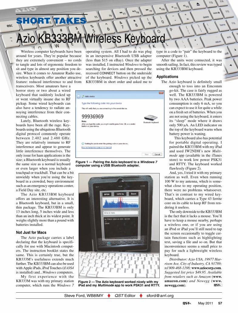
This keyboard also has potential for portable digital operating. I paired the KB333BM with my iPad and used IW2NDH’s new Multi-mode app (available in the iTunes store) to work low power PSK31 and RTTY. The keyboard worked flawlessly (Figure 2).And, yes, I tried it with my primary
station as well. Even when running 100 W to my antenna, which is some-what close to my operating position, there were no problems whatsoever. That’s in contrast to my wired key-board, which carries a Type 43 ferrite core on its cable to keep RF from ren-dering it useless.
The only downside to the KB333BM is the fact that it lacks a mouse. You’ll have to keep a mouse nearby, perhaps a wireless one, or if you are using an iPod or iPad you’ll still need to tap the screen occasionally to toggle cer- tain functions such as highlighting text, saving a file and so on. But that inconvenience seems a small price to pay for such a lightweight wireless keyboard.
Distributor: Azio USA, 19977 Har-rison Ave, City of Industry, CA 91789; tel 909-468-1198; www.aziocorp.com. Suggested list price $49.95. Available from retailers such as Amazon (www.amazon.com) and Newegg (www.newegg.com).
Figure 1 — Pairing the Azio keyboard to a Windows 7 computer using a USB Bluetooth adapter.
Figure 2 — The Azio keyboard worked nicely with my iPad and my Multimode app to work PSK31 and RTTY.
May 2011 63
Apple Camera Connection Kit (available for less than $20 on eBay and elsewhere) will al-low you to use an external USB sound device such as the Griffin Technology iMic (www.griffintechnology.com/products/imic). I tried both approaches and the input and output signal quality seemed comparable.
On the AirBefore you start Multimode, connect
your interface cable or USB audio device. I discovered through trial and error that audio re-routing must be established before you fire up the application.
I used Multimode to make some contacts during a RTTY contest and it performed quite well. Contrary to the common technique of operating your SSB transceiver in LSB for AFSK RTTY, with Multimode you must operate in USB. Multimode inverts both the input and output signals so despite the
unusual flip-flop, everything works normally.
To tune in a RTTY signal, you press and slide the tuning bar until the left hand portion is positioned over the lower of the two signals (the Space signal). Decoded text appears in the window below. If you tap twice on the spectrum display, the main window peels back to reveal a number of macro buttons, which are handy for contests and DX pileups.
Tuning PSK31 signals is a more delicate operation. I found that it helped if I zoomed the spectrum dis-play before sliding the center of the tuning bar over my signal of choice. Once I was on target, Multimode decoded the signal well, even under somewhat noisy conditions.
Portable operating was a delight with Multimode — just a Yaesu FT-817ND QRP transceiver, the KH6TY interface and my iPad. Yes, typing
on the iPad’s on-screen keyboard can be a pain, but I soon became proficient. Later I used an Azio Bluetooth wireless keyboard. You’ll find its Short Take review elsewhere in this issue.
Luca has a winner in Multimode and for $4.99 it is hard to beat. It is certainly prefer-able to lugging a laptop around the house, or into the field. Just go to the iTunes online store and enter “multimode” in the search window.
supplying a separate switching signal, or dc power for that matter. Kits are available at sites.google.com/site/kh6tyinterface/.
One word of caution: These Apple de-vices are designed to sense when an external microphone has been plugged in and they automatically reconfigure the audio signal pathways accordingly. Depending on the interface you’ve chosen, its audio output circuitry may not be recognized as a “micro-phone,” which means that the iPhone, iPod or iPad will not make the connection when you start Multimode. I ran into this issue with the KH6TY interface and the solution was to add a 2.2 kΩ resistor in series with the audio input line of the iPod Touch/iPad connector cable. That created a high enough impedance to “trick” the device into behaving as though a microphone had been connected.
If you are the owner of an iPad, you can take an entirely different approach. The
Multimode for the iPad, iPhone and iPod TouchSHORT TAKES
If you’re the proud owner of an Apple iPad, iPhone or iPod Touch, you probably know that there are a number of Amateur Radio apps (applications) for these devices. When you shop through the apps in the iTunes store, it seems as though more appear every month.
Luca Facchinetti, IW2NDH, was among the first hams to harness the processing power of the iPod Touch and iPhone to send and receive HF digital transmissions. His I-PSK31 app remains popular today and was recently updated to include a waterfall display. With his new Multimode app, Luca offers the ability to send and receive not only BPSK, but also QPSK and RTTY. Even though Multimode wasn’t developed with the iPad in mind, it also functions well on this device when enlarged to take advantage of the iPad’s display.
Getting Signals To and FromFor this review I tested Multimode on
both an iPod Touch and iPad. The new iPad 2 had just been released, but I didn’t have an opportunity to try one before press time. Based on what I’ve learned about the iPad 2, I think Multimode should be fully compatible.
The trick to using an app like Multimode is routing the audio signals to and from the transceiver. iPod Touches, iPhones and iPads all feature a combination headphone/microphone jack that requires a 1⁄8-inch 4-conductor plug. This plug is available from a number of sources including DigiKey (part number CP-354S-ND). The wiring diagram for the plug is shown in Figure 1. Apple uses an odd configuration where the top portion of the plug sleeve — the part that is commonly ground — is actually the audio input connection.
Once you have the cable/plug assembly taken care of, you need an interface to handle transmit/receive switching. The Digital VOX Sound Card Inter-face by Skip Teller, KH6TY, described in the March 2011 QST (page 34) is ideal. Since it initiates the transmit/receive switching function when it “hears” audio from the device, you don’t need to worry about
Figure 1 — Pin assignments for the Apple iPhone, iPod Touch and iPad headphone plug.