46
Product Selection Guide: T2 Series- 60 & 100 Amps

Product Selection Guide: T2 Series- 60 & 100 Amps

| StarlinePower.com
INTRODUCTION & SPECSIntroductionUniversal Electric Corporation (UEC) is the leader in electrical power distribution in the mission critical, commercial and light industrial industries with STARLINE Track Busway. This system was designed to meet the rugged specification of the UL857, Busway and Associated Fittings, with the flexible features of track lighting - and is available in systems with 60 or 100 amps with isolated ground.
It is the simple, versatile, fast and economical solution for supplying power to electrical loads and is unique because the busway can be instantly tapped at any location, with a variety of plug-in units.
The Product Selection Guide was developed to help the design engineer understand and consider all of the options available with STARLINE Track Busway when designing a system.
This guide is all-inclusive; however, UEC excels at collaborating with design engineers to provide solutions for any application. If you have a need that is not found in this guide, please contact us at 1-800-245-6378 or email us at [email protected]. We will be happy to answer your questions over the telephone or schedule a visit with one of our local representatives.
Also, if viewing this guide in print, please keep in mind that this is a working document. UEC reseves the right to change information and descriptions of listed services and products. The latest version of this guide is available for download at downloads.uecorp.com/starline/busway/.
SpecsThis specification covers the electrical characteristics and general requirements for a track busway system, hereafter referred to as (Track Busway). The system shall be designed primarily for overhead distribution of electrical power. Supporting designated work areas and equipment. Once installed the Busway will provide a simple, versatile, fast and economic means of distributing power. Loads fed from a variety of plug-in units can be easily added or removed without shutting power down to the busway.
The Track Busway shall be designed and manufactured to the following standards:
1. Underwriters Laboratories Standard, UL 857 – The common UL, CSA, and ANCE Standard for Busways that is derived from the fifth edition of CSA Standard C22.2 No. 27, the twelfth edition of UL 857, and the second edition of NMX-J-148-1998-ANCE.2. Low Voltage Switchgear and Controlgear Assemblies, Part 1: Type Tested and partially type tested Assemblies, IEC 61439-1 & IEC 61439-6.
*All standards and certifications available upon request
T2 Series
2.1

| StarlinePower.com
T2 Series
TABLE OF CONTENTSSYSTEM LAYOUT DRAWING............................................................................................................................................2.3POLARITY TIPS......................................................................................................................................................................2.4 LAYOUT TIPS..........................................................................................................................................................................2.5COMPONENT RELATIONSHIP TIPS.............................................................................................................................2.6
60T2 SystemsSTRAIGHT SECTIONS........................................................................................................................................................2.7 STRAIGHT SECTIONS: PRODUCT NUMBERS............................................................................................................2.8ELBOW SECTIONS.............................................................................................................................................................2.9 ELBOW SECTIONS: PRODUCT NUMBERS..............................................................................................................2.10TEE SECTIONS...................................................................................................................................................................2.11 TEE SECTIONS: PRODUCT NUMBERS....................................................................................................................2.12CROSS SECTIONS...........................................................................................................................................................2.13 CROSS SECTIONS: PRODUCT NUMBERS.............................................................................................................2.14END FEED UNITS...............................................................................................................................................................2.15 END FEED UNITS: PRODUCT NUMBERS.................................................................................................................2.16ABOVE FEED UNITS.........................................................................................................................................................2.17 ABOVE FEED UNITS: PRODUCT NUMBERS.............................................................................................................2.18END FEED CONNECTOR UNITS...................................................................................................................................2.19 END FEED CONNECTOR UNITS: PRODUCT NUMBERS.........................................................................................2.20BELOW FEED UNITS........................................................................................................................................................2.21 BELOW FEED UNITS: PRODUCT NUMBERS............................................................................................................2.22PENDANT FEED UNITS....................................................................................................................................................2.23 PENDANT FEED UNITS: PRODUCT NUMBERS........................................................................................................2.24
100T2 Systems STRAIGHT SECTIONS.....................................................................................................................................................2.25 STRAIGHT SECTIONS: PRODUCT NUMBERS..........................................................................................................2.26ELBOW SECTIONS...........................................................................................................................................................2.27 ELBOW SECTIONS: PRODUCT NUMBERS..............................................................................................................2.28TEE SECTIONS...................................................................................................................................................................2.29 TEE SECTIONS: PRODUCT NUMBERS.....................................................................................................................2.30CROSS SECTIONS...........................................................................................................................................................2.31 CROSS SECTIONS: PRODUCT NUMBERS.............................................................................................................2.32END FEED UNITS...............................................................................................................................................................2.33 END FEED UNITS: PRODUCT NUMBERS.................................................................................................................2.34ABOVE FEED UNITS.........................................................................................................................................................2.35 ABOVE FEED UNITS: PRODUCT NUMBERS.............................................................................................................2.36END FEED CONNECTOR UNITS...................................................................................................................................2.37 END FEED CONNECTOR UNITS: PRODUCT NUMBERS.........................................................................................2.38BELOW FEED UNITS........................................................................................................................................................2.39 BELOW FEED UNITS: PRODUCT NUMBERS............................................................................................................2.40
RAL Colors............................................................................................................................................................................2.41ACCESSORIES: SUPPORT HARDWARE..................................................................................................................2.42ACCESSORIES: SUPPORT HARDWARE..................................................................................................................2.43ACCESSORIES: CONNECTION HARDWARE.........................................................................................................2.44
2.2

| StarlinePower.com
SYSTEM LAYOUT DRAWING
End Feed Unit
Straight Section
End Cap
Tee
Elbow
Connection Hardware
T2 Series
2.3
Plug-In Unit example:
For further information on plug-in unit options, please visit the Plug-
In Units section
POLARITY TIPS
2.4 | StarlinePower.com
T2 Series
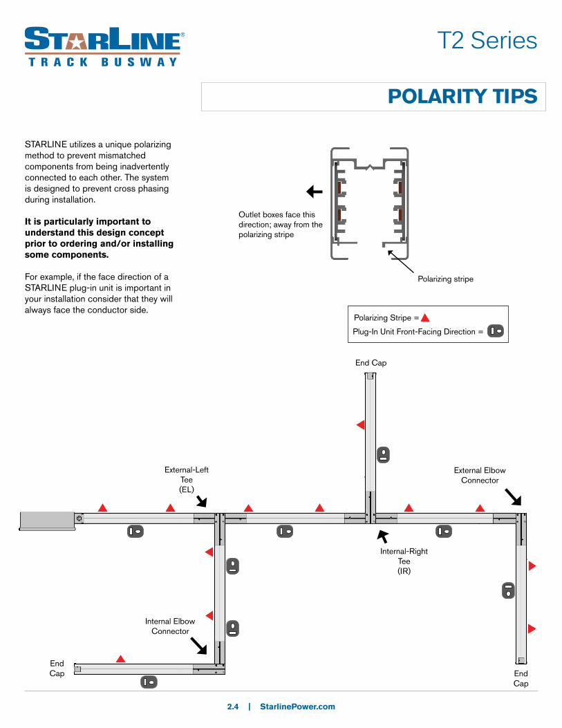
STARLINE utilizes a unique polarizing method to prevent mismatched components from being inadvertently connected to each other. The system is designed to prevent cross phasing during installation.
It is particularly important to understand this design concept prior to ordering and/or installing some components.
For example, if the face direction of a STARLINE plug-in unit is important in your installation consider that they will always face the conductor side.
Outlet boxes face this direction; away from the polarizing stripe
End Cap
End Cap
Internal-Right Tee (IR)
External-LeftTee (EL)
Polarizing stripe
End Cap
Internal Elbow Connector
External Elbow Connector
Polarizing Stripe =
Plug-In Unit Front-Facing Direction =
SYSTEM LAYOUT TIPS
2.5 | StarlinePower.com
T2 Series
Power FeedsDetermine location of power feeds based on relation to power source, existing feeders and voltage drop concerns for longer runs.
Support HardwareSupport hardware is spaced no more than 10 ft apart. Refer to page 2.42 for support hardware details. Contact your local Starline applications engineer for any questions.
InstallationPrinted installation drawings are supplied with each system shipment and they are also available for download online at http://downloads.uecorp.com/starline/busway/. CAD files of these drawings are also available by contacting your local Starline applications engineer.
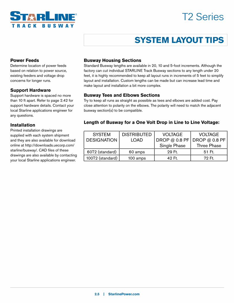
Busway Housing SectionsStandard Busway lengths are available in 20, 10 and 5-foot increments. Although the factory can cut individual STARLINE Track Busway sections to any length under 20 feet, it is highly recommended to keep all layout runs in increments of 5 feet to simplify layout and installation. Custom lengths can be made but can increase lead time and make layout and installation a bit more complex.
Busway Tees and Elbows SectionsTry to keep all runs as straight as possible as tees and elbows are added cost. Pay close attention to polarity on the elbows. The polarity will need to match the adjacent busway section(s) to be compatible.
Length of Busway for a One Volt Drop in Line to Line Voltage:
SYSTEM DESIGNATION
DISTRIBUTED LOAD
VOLTAGE DROP @ 0.8 PF
Single Phase
VOLTAGE DROP @ 0.8 PF
Three Phase60T2 (standard) 60 amps 29 Ft. 51 Ft.
100T2 (standard) 100 amps 42 Ft. 72 Ft.
COMPONENT RELATIONSHIP TIPS
2.6 | StarlinePower.com
T2 Series
When ordering material, it is important to understand the relationship between various components.
Examples:
• No need to add extra Joint Kits for Elbows, Tees, or Crosses, as they are already part of your housing count.
• If using an Above Feed, order a Joint Kit for each Feed.
• General support hardware rule to follow:
10 ft maximum spacing between supports and we recommend 10% more than the required quantity to cover potential layout changes.
• Total Power Feeds and End Caps can be determined by counting the total number of unconnected runs.
• Before specifying or ordering elbow or tee connectors, it is important to understand polarity and the relationship to direction of outlets. Please refer to pg. 2.4 Polarity Tips for more detail.

60T2 System
STRAIGHT SECTIONS
Product DescriptionTrack Busway straight sections consist of an extruded aluminum shell with insulated copper conductor strips mounted on the two opposite interior side walls. The aluminum housing acts as a 100% ground path and each straight has an open access slot over its entire length for the insertion of turn-n-lock plug-in units. The housing configuration is 4 pole in a 300 Volt design. Track Busway housing is connected together using in-line connectors and housing couplers (found under Accessories).
2.7 | StarlinePower.com
MATERIAL: Extruded Aluminum
RATINGS: 100% Ground Path
U.S: 60 Amp, 300 Volt
LENGTH: 5 Ft, 10 Ft, 20 Ft.; or custom lengths between 2 - 20 Ft.
VOLTAGE DROP: distributed load
Single Phase 29 ft. (.8PF)
Three Phase 51 ft. (.8PF)
2.58”
1.79”
Housing Coupler: placed over top of
connector to make a mechanical connection
In-Line Connector: placed in between
two pieces of busway to make an electrical
connection
Four Pole
(N)
(L1)
(L2)
(L3)
L1 = BlueL2 = BlackL3 = RedN = white or beige
WEIGHT:
10 ft. 4 pole: 12.5 lbs

60T2 System
STRAIGHT SECTIONS: PRODUCT NUMBERS
2.8 | StarlinePower.com
U S 060 T2 C 4 S - 0200 C
- STD0 10. Paint color
1. System
2. Product Type
3. Product Frame
4. Compat-ibility
5.Material
6.Neutral/Ground busbar
7.Polarization
8. Straight Length
9.Busway Access
**RAL (please see page 2.41)
1. System (standard of measure)U U.S.
2. Product Type (section component)S Straight section
3. Product Frame (maximum amperage)060 60 amps
4. Compatibility (frame compatibility)T2 T2 systems
5. Material (busbar material)C Copper
6. Neutral/Ground Busbar (size of neutral busbar and/or ground)
7. Polarization (orientation of section for mating purposes)S Standard
8. Straight Length (length of section)XXYY XX = feet, YY = inches
9. Busway Access (how plugs access the busway)C Continuous
4 3 Phase plus Neutral
10. Paint Color (allows painting of the busway housing)STD0 UEC Mill FinishBLK0 Paint UEC BlackWHT0 Paint UEC White
RED0 Paint UEC RedBLU0 Paint UEC Blue
Examples:
US060T2C4S-1000C-STD0 = US, Straight section, 60 amps, T2, Copper conductor, 3 Phase plus neutral, Standard polarization- 10ft., Continuous access- standard mill finishUS060T2C4S-0500C-P010 = US, Straight section, 60 amps, T2, Copper conductor, 3 phase plus neutral, Standard polarization- 5ft., Continuous access- RAL 1001

60T2 System
ELBOW SECTIONS
Product DescriptionElbow connectors are used for making a 90 degree turn in a 60 amp Busway run. Please be aware of polarization issues before making your final selection (refer to pg. 2.4 Polarity Tips).
Elbows are electrically connected to sections of 60 amp Busway by means of an in-line connector. The connector is installed by inserting in each end of the housing sections to be joined. Hex head compression screws are tightened to make a reliable connection. All in-line connectors are polarized to prevent phase mismatch.
2.9 | StarlinePower.com
Elbow Connector
In-Line Connector
= Polarizing Stripe
External ElbowInternal Elbow
WEIGHT: .5 lbs

60T2 System
ELBOW SECTIONS: PRODUCT NUMBERS
2.10 | StarlinePower.com
U E 060 T2 C 4 S - IN
- STD09. Paint color
1. System
2. Product Type
3. Product Frame
4. Compat-ibility
5.Material
6.Neutral/Ground busbar
7.Polarization
8. Turning Direction
1. System (standard of measure)U U.S.
2. Product Type (section component)E Elbow section
3. Product Frame (maximum amperage)060 60 amps
4. Compatibility (frame compatibility)T2 T2 systems
5. Material (busbar material)C Copper
6. Neutral/Ground Busbar (size of neutral busbar and/or ground)
7. Polarization (orientation of section for mating purposes)S Standard
8. Turning Direction (direction of section polarizing stripe)IN Internal EX External
4 3 Phase plus Neutral
9. Paint Color (allows painting of the busway housing) STD0 UEC Mill Finish BLK0 Paint UEC BlackWHT0 Paint UEC White
**RAL system can also be used; reference page 2.41
RED0 Paint UEC RedBLU0 Paint UEC Blue
Examples:
UE060T2C4S-IN-BLK0 = US, Elbow section, 60 amps, T2, Copper conductor, 3 Phase plus neutral, Standard polarization- Internal- painted blackUE060T2C4S-EX-STD0 = US, Elbow section, 60 amps, T2, Copper conductor, 3 phase plus neutral, Standard polarization- External- standard mill finish
**RAL (please see page 2.41)

60T2 System
TEE SECTIONS
Product DescriptionSimilar to elbow connectors, tee connectors are used for connecting branch housing sections at 90 degrees to the main run. Please be aware of polarization issues before making your final selection (refer to pg. 2.4 Polarity Tips).
Tees are electrically connected to sections of 60 amp Busway by means of an in-line connector. The connector is installed by inserting in each end of the housing sections to be joined. Hex head compression screws are tightened to make a reliable connection. All in-line connectors are polarized to prevent phase mismatch.
2.11 | StarlinePower.com
External-Left(EL)
External-Right(ER)
Internal-Left(IL)
Internal-Right(IR)
In-line Connector = Polarizing Stripe
WEIGHT: 1 lb
60T2 Systems
TEE SECTIONS: PRODUCT NUMBERS
2.12 | StarlinePower.com
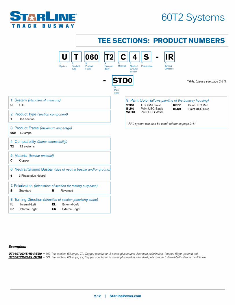
U T 060 T2 C 4 S - IR
- STD09. Paint color
1. System
2. Product Type
3. Product Frame
4. Compat-ibility
5.Material
6.Neutral/Ground busbar
7.Polarization
8. Turning Direction
1. System (standard of measure)U U.S.
2. Product Type (section component)T Tee section
3. Product Frame (maximum amperage)060 60 amps
4. Compatibility (frame compatibility)T2 T2 systems
5. Material (busbar material)C Copper
7. Polarization (orientation of section for mating purposes)S Standard R Reversed
8. Turning Direction (direction of section polarizing stripe)IL Internal-Left EL External-Left
IR Internal-Right ER External-Right
9. Paint Color (allows painting of the busway housing)
STD0 UEC Mill FinishBLK0 Paint UEC BlackWHT0 Paint UEC White
**RAL system can also be used; reference page 2.41
RED0 Paint UEC RedBLU0 Paint UEC Blue
Examples:
UT060T2C4S-IR-RED0 = US, Tee section, 60 amps, T2, Copper conductor, 3 phase plus neutral, Standard polarization- Internal-Right- painted redUT060T2C4S-EL-STD0 = US, Tee section, 60 amps, T2, Copper conductor, 3 phase plus neutral, Standard polarization- External-Left- standard mill finish
**RAL (please see page 2.41)
6. Neutral/Ground Busbar (size of neutral busbar and/or ground)
4 3 Phase plus Neutral

60T2 System
CROSS SECTIONS
Product DescriptionSimilar to tee connectors, crosses are typically used for grid designs. Please be aware of polarization issues before making your final selection (refer to pg. 2.4 Polarity Tips).
Crosses are electrically connected to sections of 60 amp Busway by means of an in-line connector. The connector is installed by inserting in each end of the housing sections to be joined. Hex head compression screws are tightened to make a reliable connection. All in-line connectors are polarized to prevent phase mismatch.
2.13 | StarlinePower.com
In-line Connector
Standard cross
= Polarizing Stripe

60T2 Systems
CROSS SECTIONS: PRODUCT NUMBERS
2.14 | StarlinePower.com
U X 060 T2 C 4 S - ST
- STD0
1. System
2. Product Type
3. Product Frame
4. Compat-ibility
5.Material
6.Neutral/Ground busbar
7.Polarization
8. Turning Direction
1. System (standard of measure)U U.S.
2. Product Type (section component)X Cross section
3. Product Frame (maximum amperage)060 60 amps
4. Compatibility (frame compatibility)T2 T2 systems
5. Material (busbar material)C Copper
7. Polarization (orientation of section for mating purposes)S Standard
8. Turning Direction (direction of section polarizing stripe)ST Standard
9. Paint Color (allows painting of the busway housing)STD0 UEC Mill FinishBLK0 Paint UEC BlackWHT0 Paint UEC White
**RAL system can also be used; reference page 2.41
RED0 Paint UEC RedBLU0 Paint UEC Blue
Examples:
UX060T2C4S-ST-RED0 = US, cross section, 60 amps, T2, Copper conductor, 3 Phase plus neutral, Standard polarization- Standard turning direction- painted redUX060T2C4S-ST-STD0 = US, cross section, 60 amps, T2, Copper conductor, 3 phase plus neutral, Standard polarization- Standard turning direction- standard mill finish
**RAL (please see page 2.41)
6. Neutral/Ground Busbar (size of neutral busbar and/or ground)
4 3 Phase plus Neutral
9. Paint Color

60T2 Systems
END FEED UNITSProduct DescriptionWith a built-in connector, the end feed units for 60T2 systems consist of a steel junction box with removable side, a terminal block for field connections and an in-line connector already terminated to one side of the terminal block.
The unit is inserted into the Busway and held in position via a bolted connection to the Busway.
2.15 | StarlinePower.com
-
4.5”
9.25”
standard orientation
reversed orientation
Top View
3”
WEIGHT: 3.5 lbs
60T2 Systems
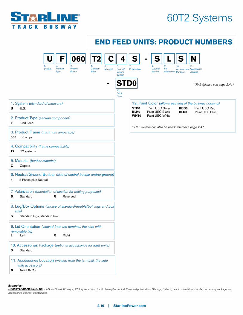
END FEED UNITS: PRODUCT NUMBERS
2.16 | StarlinePower.com
U F 060 T2 C 4 S - S L S N
- STD0
1. System
2. Product Type
3. Product Frame
4. Compat-ibility
5.Material
6.Neutral/Ground busbar
7.Polarization
8. Lug/box options
9.Lid orientation
10.AccessoriesPackage
11.Accessories Location
1. System (standard of measure)U U.S.
2. Product Type (section component)F End Feed
3. Product Frame (maximum amperage)060 60 amps
4. Compatibility (frame compatibility)T2 T2 systems
5. Material (busbar material)C Copper
6. Neutral/Ground Busbar (size of neutral busbar and/or ground)
7. Polarization (orientation of section for mating purposes)S Standard R Reversed
8. Lug/Box Options (choice of standard/double/bolt lugs and box size)S Standard lugs, standard box
9. Lid Orientation (viewed from the terminal, the side with removable lid)L Left R Right
10. Accessories Package (optional accessories for feed units)S Standard
11. Accessories Location (viewed from the terminal, the side with accessory)N None (N/A)
4 3 Phase plus Neutral
12. Paint Color (allows painting of the busway housing)STD0 Paint UEC SilverBLK0 Paint UEC BlackWHT0 Paint UEC White
**RAL system can also be used; reference page 2.41
RED0 Paint UEC RedBLU0 Paint UEC Blue
Examples:UF060T2C4R-SLSN-BLU0 = US, end Feed, 60 amps, T2, Copper conductor, 3 Phase plus neutral, Reversed polarization- Std lugs, Std box, Left lid orientation, standard accessory package, no accessories location- painted blue
**RAL (please see page 2.41)
12. Paint Color

60T2 Systems
ABOVE FEED UNITS
Product DescriptionThe above feed unit is used for supplying power anywhere along the top of a Busway run. It consists of a two-foot section of Busway, and a junction box with a 60A rated terminal block.
Two in-line connectors and housing couplers (supplied separately) are used to connect two adjacent busway sections.
2.17 | StarlinePower.com
4.25”
2'
9.25”
WEIGHT: 2 - 5 lbs
Internal View

60T2 Systems
ABOVE FEED UNITS: PRODUCT NUMBERS
2.18 | StarlinePower.com
U A 060 T2 C 4 S - S N S N - 0200 C 012
- STD0
1. System
2. Product Type
3. Product Frame
4. Compat-ibility
5.Material
6.Neutral/Ground busbar
7.Polarization
8. Lug/box options
9.Lid orientation
10.AccessoriesPackage
11.Accessories Location
12. Straight Length
13.Busway Access
1. System (standard of measure)U U.S.
2. Product Type (section component)A Above Feed
3. Product Frame (maximum amperage)060 60 amps
4. Compatibility (frame compatibility)T2 T2 systems
5. Material (busbar material)C Copper
6. Neutral/Ground Busbar (size of neutral busbar and/or ground)
7. Polarization (orientation of section for mating purposes)S Standard R Reversed
8. Lug Options (other than standard lugs, there is also the option for double lugs and bolt lugs)S Standard lugs, standard box
9. Lid Orientation (viewed from the terminal, the side with removable lid)N None (N/A)
10. Accessories Package (optional accessories for feed units)S Standard
12. Straight Length (length of section)0200 2 feet
13. Busway Access (how plugs access the busway)C Continuous
4 3 Phase plus Neutral
15. Paint Color (allows painting of the busway housing)STD0 Paint UEC Silver BLK0 Paint UEC BlackWHT0 Paint UEC White
**RAL system can also be used; reference page 2.41
RED0 Paint UEC RedBLU0 Paint UEC Blue
Examples:UA060T2C4S-SNSN-0200C012-BLK0 = US, Above feed, 60 amps, T2, Copper conductor, 3 phase plus neutral, Standard polarization- Std lugs, Std box, No lid orientation, Standard accessory package, No accessory location- 2 ft., Continuous access, 12 inches- painted black
11. Accessories Location (viewed from the terminal, the side with accessory)N None (N/A)
14. Feed Location (location of the center of the top feed)012 12 inches
14.Feed Location
**RAL (please see page 2.41)
15. Paint Color

Product DescriptionThis design of power feed has a built-in connector and is used primarily in applications where aesthetic appearance is important- such as retail.
Wire leads are preassembled to the connector and eliminate the junction box on the Busway.
24 in wire length is standard, but additional lengths are available upon request.
2.19 | StarlinePower.com
60T2 Systems
END FEED CONNECTOR UNITS
End Cap
Connector
WEIGHT: 2 lbs

60T2 Systems
END FEED CONNECTOR UNITS: PRODUCT NUMBERS
2.20 | StarlinePower.com
U C 060 T2 C 4 S - 024 1. System
2. Product Type
3. Product Frame
4. Compat-ibility
5.Material
6.Neutral/Ground busbar
7.Polarization
8. Wire Length
1. System (standard of measure)U U.S.
2. Product Type (section component)C Concealed feed
3. Product Frame (maximum amperage)060 60 amps
4. Compatibility (frame compatibility)T2 T2 systems
5. Material (busbar material)C Copper
6. Neutral/Ground Busbar (size of neutral busbar and/or ground)
7. Polarization (orientation of section for mating purposes)S Standard
8. Wire Length (length of wire from the connector - in inches)ZZZ ZZZ = inches (024 is standard)
4 3 Phase plus Neutral
Examples:UC060T2C4S-024 = US, Concealed feed, 60 amps, T2, Copper conductor, 3 phase plus neutral, Standard polarization- 24 inches

Product DescriptionA Below Power Feed is designed to be installed anywhere along the full-access opening of a Busway run. Insert the Power Feed connector into the Busway run where desired and secure with a hanger bolt (supplied). The Below Power Feed unit must be completely installed in the selected Busway housing before the adjacent housing section can be installed. A terminal block is provided in the box for field terminations. Power supply cable is fed in from under the unit.
2.21 | StarlinePower.com
60T2 Systems
BELOW FEED UNITS
WEIGHT: 4.8 lbs

60T2 Systems
BELOW FEED UNITS: PRODUCT NUMBERS
2.22 | StarlinePower.com
U B 060 T2 C 4 S - S R S N
- GAL0
1. System
2. Product Type
3. Product Frame
4. Compat-ibility
5.Material
6.Neutral/Ground busbar
7.Polarization
8. Lug/box options
9.Lid orientation
10.AccessoriesPackage
11.Accessories Location
1. System (standard of measure)U U.S.
2. Product Type (section component)B Below Feed
3. Product Frame (maximum amperage)060 60 amps
4. Compatibility (frame compatibility)T2 T2 systems
5. Material (busbar material)C Copper
6. Neutral/Ground Busbar (size of neutral busbar and/or ground)
7. Polarization (orientation of section for mating purposes)S Standard R Reversed
8. Lug Options (other than standard lugs, there is also the option for double lugs and bolt lugs)S Standard lugs, standard box
9. Lid Orientation (viewed from the terminal, the side with meter)R Right
10. Accessories Package (optional accessories for feed units)S Standard
4 3Phase plus Neutral
15. Paint Color (allows painting of the busway housing)GAL0 Galvanized BLK0 Paint UEC BlackWHT0 Paint UEC White
**RAL system can also be used; reference page 2.41
RED0 Paint UEC RedBLU0 Paint UEC Blue
Examples:UB060T2C4S-SRSN-GAL0 = US, Below feed, 60 amps, T2, Copper conductor, 3Phase plus neutral, Standard polarization- Std lugs, Std box, Right lid orientation, Standard accessory package, No accessory location- Galvanized
11. Accessories Location (viewed from the terminal, the side with accessory)N None (N/A)
**RAL (please see page 2.41)
15. Paint Color

Product DescriptionA Pendant Feed consists of a 1 ft. Busway section with a 1 inch conduit size access hole for access to connection leads inside the Busway. A 1 inch conduit mounting adapter is included.
2.23 | StarlinePower.com
60T2 Systems
PENDANT FEED UNITS
Hole used to access connection leads with the Busway
12”
60T2 Systems
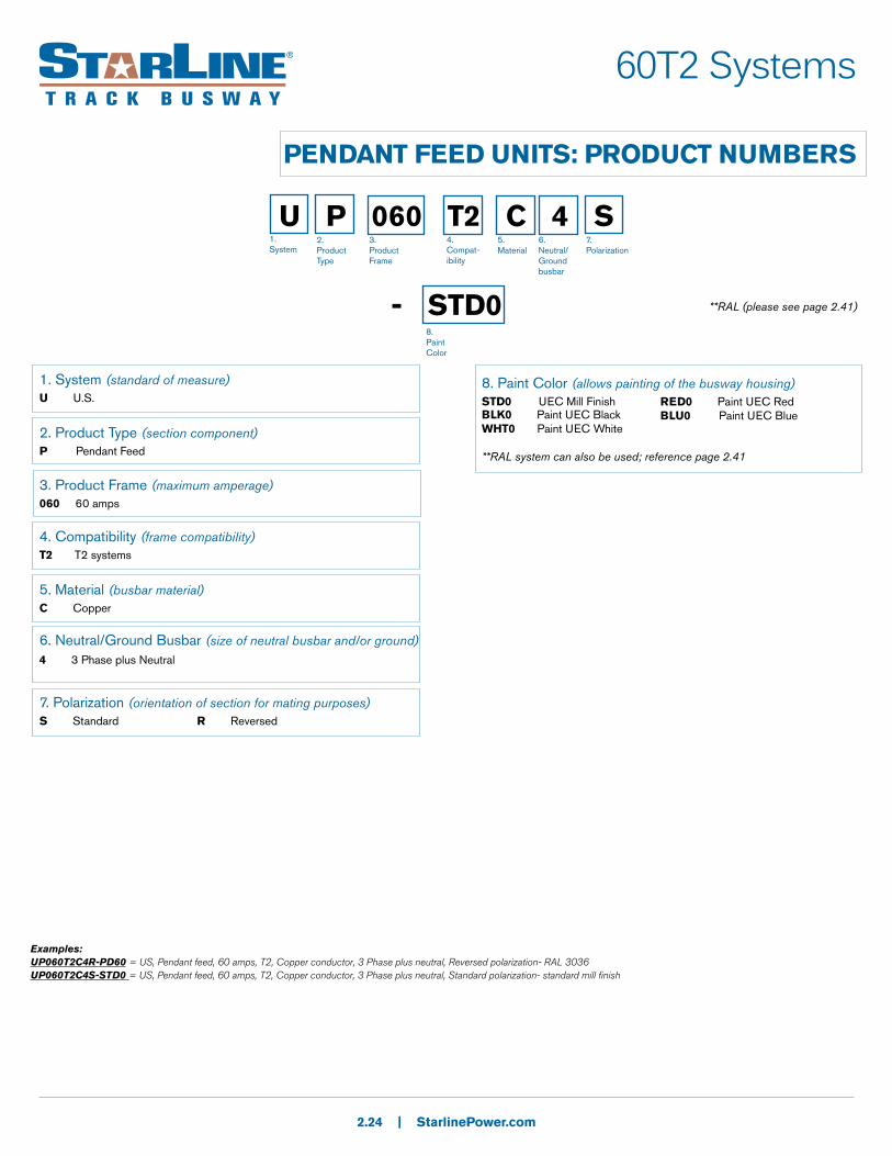
PENDANT FEED UNITS: PRODUCT NUMBERS
2.24 | StarlinePower.com
U P 060 T2 C 4 S
- STD0
1. System
2. Product Type
3. Product Frame
4. Compat-ibility
5.Material
6.Neutral/Ground busbar
7.Polarization
1. System (standard of measure)U U.S.
2. Product Type (section component)P Pendant Feed
3. Product Frame (maximum amperage)060 60 amps
4. Compatibility (frame compatibility)T2 T2 systems
5. Material (busbar material)C Copper
6. Neutral/Ground Busbar (size of neutral busbar and/or ground)
7. Polarization (orientation of section for mating purposes)S Standard R Reversed
4 3 Phase plus Neutral
8. Paint Color (allows painting of the busway housing) STD0 UEC Mill FinishBLK0 Paint UEC BlackWHT0 Paint UEC White
**RAL system can also be used; reference page 2.41
RED0 Paint UEC RedBLU0 Paint UEC Blue
Examples:UP060T2C4R-PD60 = US, Pendant feed, 60 amps, T2, Copper conductor, 3 Phase plus neutral, Reversed polarization- RAL 3036UP060T2C4S-STD0 = US, Pendant feed, 60 amps, T2, Copper conductor, 3 Phase plus neutral, Standard polarization- standard mill finish
**RAL (please see page 2.41)
8. Paint Color

100T2 System
STRAIGHT SECTIONS
Product DescriptionTrack Busway straight sections consist of an extruded aluminum shell with insulated copper conductor strips mounted on the two opposite interior side walls. The aluminum extrusion acts as a 100% ground path and each straight has an open access slot over its entire length for the insertion of turn-n-lock plug-in units. The housing configuration is 4 pole in a 600 Volt design. Track Busway straights are connected together using in-line connectors and housing couplers (found under Accessories).
2.25 | StarlinePower.com
MATERIAL: Extruded Aluminum
RATINGS: 100% Ground Path
100 Amp, 600 Volt
LENGTH: 5 Ft, 10 Ft, 20 Ft.; or custom lengths between 2 - 20 Ft.
VOLTAGE DROP: distributed load
Single Phase 42 ft. (.85PF)
Three Phase 72 ft. (.85PF)2.58”
1.79”
Housing Coupler: placed over top of
connector to make a mechanical connection
In-Line Connector: placed in between
two pieces of busway to make an electrical
connection
Four Pole
(N)
(L1)
(L2)
(L3)
L1 = BlueL2 = BlackL3 = RedN = white or beige
WEIGHT:
10 ft. (3m) 4 pole: 16 lbs

100T2 System
STRAIGHT SECTIONS: PRODUCT NUMBERS
2.26 | StarlinePower.com
U S 100 T2 C 4 S - 0200 C
- STD0 10. Paint color
1. System
2. Product Type
3. Product Frame
4. Compat-ibility
5.Material
6.Neutral/Ground busbar
7.Polarization
8. Straight Length
9.Busway Access
**RAL (please see page 2.41)
1. System (standard of measure)U U.S.
2. Product Type (section component)S Straight section
3. Product Frame (maximum amperage)100 100 amps
4. Compatibility (frame compatibility)T2 T2 systems
5. Material (busbar material)C Copper
6. Neutral/Ground Busbar (size of neutral busbar and/or ground)
7. Polarization (orientation of section for mating purposes)S Standard
8. Straight Length (length of section)XXYY XX = feet, YY = inches (for U.S.)
9. Busway Access (how plugs access the busway)C Continuous
4 3 Phase plus Neutral
10. Paint Color (allows painting of the busway housing)
STD0 UEC Mill FinishBLK0 Paint UEC BlackWHT0 Paint UEC White
**RAL system can also be used; reference page 2.41
RED0 Paint UEC RedBLU0 Paint UEC Blue
Examples:
US100T2C4S-0206C-STD0 = US, Straight section, 100 amps, T2, Copper conductor, 3 Phase plus neutral, Standard polarization- 2ft. 6in., Continuous access- standard mill finishUS100T2C4S-0500C-P010 = US, Straight section, 100 amps, T2, Copper conductor, 3 phase plus neutral, Standard polarization- 5ft., Continuous access- RAL 1001

100T2 System
ELBOW SECTIONS
Product DescriptionElbow connectors are used for making a 90 degree turn in a 100 amp compact Busway run. Please be aware of polarization issues before making your final selection (refer to pg. 2.4 Polarity Tips).
Elbows are electrically connected to sections of 100 amp Busway by means of an in-line connector. The connector is installed by inserting in each end of the housing sections to be joined. Hex head compression screws are tightened to make a reliable connection. All in-line connectors are polarized to prevent phase mismatch.
2.27 | StarlinePower.com
Elbow Connector
In-line Connector
Internal Elbow External Elbow
= Polarizing Stripe
WEIGHT: .5 lbs

100T2 System
ELBOW SECTIONS: PRODUCT NUMBERS
2.28 | StarlinePower.com
U E 100 T2 C 4 S - IN
- STD0 9. Paint color
1. System
2. Product Type
3. Product Frame
4. Compat-ibility
5.Material
6.Neutral/Ground busbar
7.Polarization
8. Turning Direction
1. System (standard of measure)U U.S.
2. Product Type (section component)E Elbow section
3. Product Frame (maximum amperage)100 100 amps
4. Compatibility (frame compatibility)T2 T2 systems
5. Material (busbar material)C Copper
6. Neutral/Ground Busbar (size of neutral busbar and/or ground)
7. Polarization (orientation of section for mating purposes)S Standard
8. Turning Direction (direction of section polarizing stripe)IN Internal EX External
4 3 Phase plus Neutral
9. Paint Color (allows painting of the busway housing)
STD0 UEC Mill Finish BLK0 Paint UEC BlackWHT0 Paint UEC White
**RAL system can also be used; reference page 2.41
RED0 Paint UEC RedBLU0 Paint UEC Blue
Examples:
UE100T2C4S-IN-BLK0 = US, Elbow section, 100 amps, T2, Copper conductor, 3 Phase plus neutral, Standard polarization- Internal- painted blackUE100T2C4S-EX-STD0 = US, Elbow section, 100 amps, T2, Copper conductor, 3 phase plus neutral, Standard polarization- External- standard mill finish
**RAL (please see page 2.41)

100T2 System
TEE SECTIONS
Product DescriptionSimilar to elbow connectors, tee connectors are used for connecting branch housing sections at 90 degrees to the main run. Please be aware of polarization issues before making your final selection (refer to pg. 2.4 Polarity Tips).
Tees are electrically connected to sections of 100 amp Busway by means of an in-line connector. The connector is installed by inserting in each end of the housing sections to be joined. Hex head compression screws are tightened to make a reliable connection. All in-line connectors are polarized to prevent phase mismatch.
2.29 | StarlinePower.com
External-Left(EL)
External-Right(ER)
Internal-Left(IL)
Internal-Right(IR)
= Polarizing Stripe
In-line Connector
WEIGHT: 1 lb

100T2 Systems
TEE SECTIONS: PRODUCT NUMBERS
2.30 | StarlinePower.com
U T 100 T2 C 4 S - IR
- STD0
1. System
2. Product Type
3. Product Frame
4. Compat-ibility
5.Material
6.Neutral/Ground busbar
7.Polarization
8. Turning Direction
1. System (standard of measure)U U.S.
2. Product Type (section component)T Tee section
3. Product Frame (maximum amperage)100 100 amps
4. Compatibility (frame compatibility)T2 T2 systems
5. Material (busbar material)C Copper
7. Polarization (orientation of section for mating purposes)S Standard R Reversed
8. Turning Direction (direction of section polarizing stripe)IL Internal-Left EL External-Left
IR Internal-Right ER External-Right
9. Paint Color (allows painting of the busway housing)
STD0 UEC Mill Finish BLK0 Paint UEC BlackWHT0 Paint UEC White
**RAL system can also be used; reference page 2.41
RED0 Paint UEC RedBLU0 Paint UEC Blue
Examples:
UT100T2C4S-IR-RED0 = US, Tee section, 100 amps, T2, Copper conductor, 3 phase plus neutral, Standard polarization- Internal-Right- painted redUT100T2C4S-EL-STD0 = US, Tee section, 100 amps, T2, Copper conductor, 3 phase plus neutral, Standard polarization- External-Left- standard mill finish
**RAL (please see page 2.41)
6. Neutral/Ground Busbar (size of neutral busbar and/or ground)
4 3 Phase plus Neutral
9. Paint Color
100T2 System
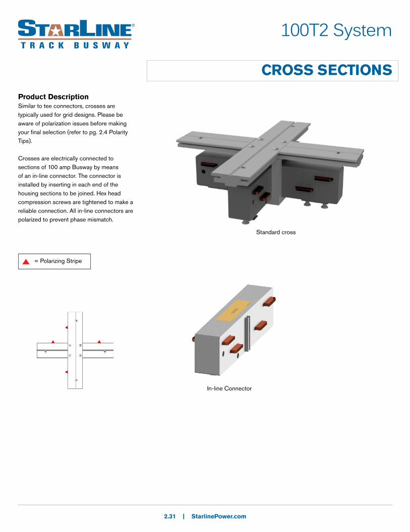
CROSS SECTIONS
Product DescriptionSimilar to tee connectors, crosses are typically used for grid designs. Please be aware of polarization issues before making your final selection (refer to pg. 2.4 Polarity Tips).
Crosses are electrically connected to sections of 100 amp Busway by means of an in-line connector. The connector is installed by inserting in each end of the housing sections to be joined. Hex head compression screws are tightened to make a reliable connection. All in-line connectors are polarized to prevent phase mismatch.
2.31 | StarlinePower.com
In-line Connector
Standard cross
= Polarizing Stripe

100T2 Systems
CROSS SECTIONS: PRODUCT NUMBERS
2.32 | StarlinePower.com
U X 100 T2 C 4 S - ST
- STD0
1. System
2. Product Type
3. Product Frame
4. Compat-ibility
5.Material
6.Neutral/Ground busbar
7.Polarization
8. Turning Direction
1. System (standard of measure)U U.S.
2. Product Type (section component)X Cross section
3. Product Frame (maximum amperage)100 100 amps
4. Compatibility (frame compatibility)T2 T2 systems
5. Material (busbar material)C Copper
7. Polarization (orientation of section for mating purposes)S Standard
8. Turning Direction (direction of section polarizing stripe)ST Standard
9. Paint Color (allows painting of the busway housing)STD0 UEC Mill FinishBLK0 Paint UEC BlackWHT0 Paint UEC White
**RAL system can also be used; reference page 2.41
RED0 Paint UEC RedBLU0 Paint UEC Blue
Examples:
UX100T2C4S-ST-RED0 = US, cross section, 100 amps, T2, Copper conductor, 3 phase plus neutral, Standard polarization- Standard turning direction- painted redUX100T2C4S-ST-STD0 = US, cross section, 100 amps, T2, Copper conductor, 3 phase plus neutral, Standard polarization- Standard turning direction- standard mill finish
**RAL (please see page 2.41)
6. Neutral/Ground Busbar (size of neutral busbar and/or ground)
4 3 Phase plus Neutral
9. Paint color
100T2 Systems
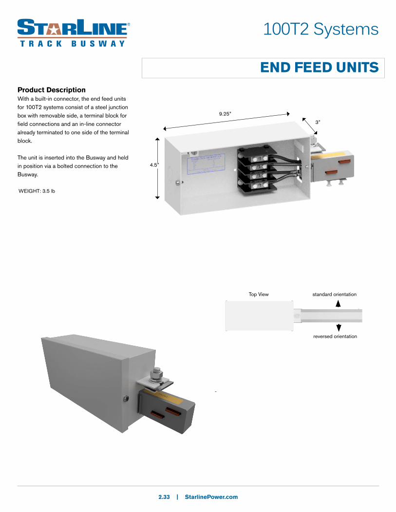
END FEED UNITSProduct DescriptionWith a built-in connector, the end feed units for 100T2 systems consist of a steel junction box with removable side, a terminal block for field connections and an in-line connector already terminated to one side of the terminal block.
The unit is inserted into the Busway and held in position via a bolted connection to the Busway.
2.33 | StarlinePower.com
-
4.5”
9.25”
standard orientation
reversed orientation
Top View
3”
WEIGHT: 3.5 lb

100T2 Systems
END FEED UNITS: PRODUCT NUMBERS
2.34 | StarlinePower.com
U F 100 T2 C 4 S - S L S N
- STD0
1. System
2. Product Type
3. Product Frame
4. Compat-ibility
5.Material
6.Neutral/Ground busbar
7.Polarization
8. Lug/box options
9.Lid orientation
10.AccessoriesPackage
11.Accessories Location
1. System (standard of measure)U U.S.
2. Product Type (section component)F End Feed
3. Product Frame (maximum amperage)100 100 amps
4. Compatibility (frame compatibility)T2 T2 systems
5. Material (busbar material)C Copper
6. Neutral/Ground Busbar (size of neutral busbar and/or ground)
7. Polarization (orientation of section for mating purposes)S Standard R Reversed
8. Lug/Box Options (choice of standard/double/bolt lugs and box size)S Standard lugs, standard box
9. Lid Orientation (viewed from the terminal, the side with removable lid)L Left R Right
10. Accessories Package (optional accessories for feed units)S Standard
11. Accessories Location (viewed from the terminal, the side with accessory)N None (N/A)
4 3Phase plus Neutral
12. Paint Color (allows painting of the busway housing)
STD0 Paint UEC Silver BLK0 Paint UEC BlackWHT0 Paint UEC White
**RAL system can also be used; reference page 2.41
RED0 Paint UEC RedBLU0 Paint UEC Blue
Examples:UF100T2C4R-SLSN-BLU0 = US, end Feed, 100 amps, T2, Copper conductor, 3 phase plus neutral, Reversed polarization- Std lugs, Std box, Left lid orientation, standard accessory package, no accessories location- painted blue
**RAL (please see page 2.41)
12. Paint Color
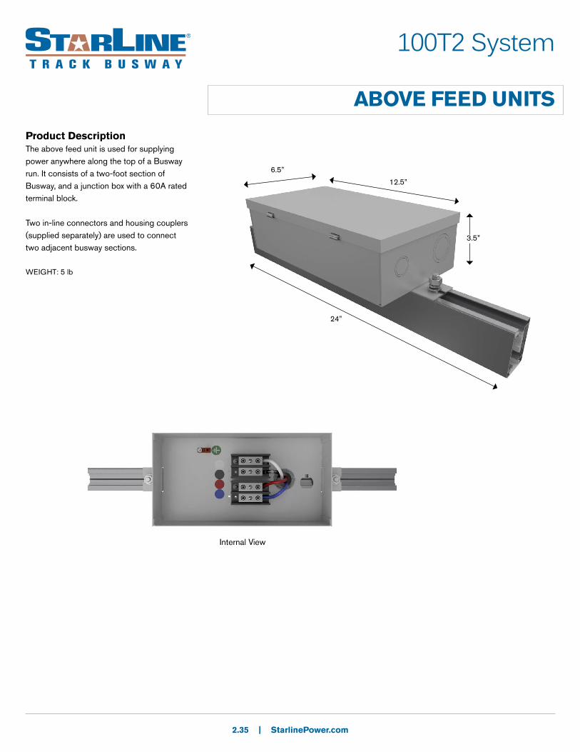
Product DescriptionThe above feed unit is used for supplying power anywhere along the top of a Busway run. It consists of a two-foot section of Busway, and a junction box with a 60A rated terminal block.
Two in-line connectors and housing couplers (supplied separately) are used to connect two adjacent busway sections.
2.35 | StarlinePower.com
12.5”
6.5”
100T2 System
ABOVE FEED UNITS
3.5”
Internal View
24”
WEIGHT: 5 lb
100T2 Systems
ABOVE FEED UNITS: PRODUCT NUMBERS
2.36 | StarlinePower.com
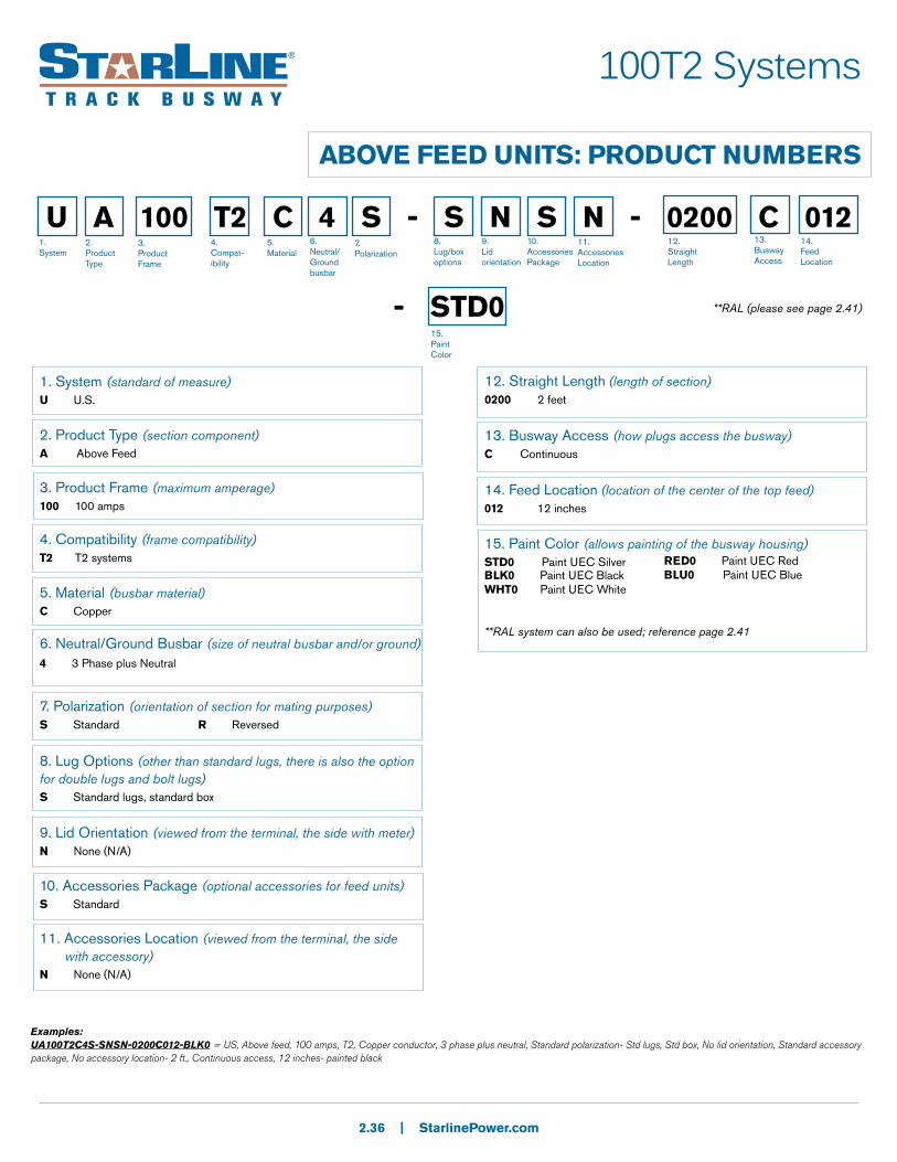
U A 100 T2 C 4 S - S N S N - 0200 C 012
- STD0
1. System
2. Product Type
3. Product Frame
4. Compat-ibility
5.Material
6.Neutral/Ground busbar
7.Polarization
8. Lug/box options
9.Lid orientation
10.AccessoriesPackage
11.Accessories Location
12. Straight Length
13.Busway Access
1. System (standard of measure)U U.S.
2. Product Type (section component)A Above Feed
3. Product Frame (maximum amperage)100 100 amps
4. Compatibility (frame compatibility)T2 T2 systems
5. Material (busbar material)C Copper
6. Neutral/Ground Busbar (size of neutral busbar and/or ground)
7. Polarization (orientation of section for mating purposes)S Standard R Reversed
8. Lug Options (other than standard lugs, there is also the option for double lugs and bolt lugs)S Standard lugs, standard box
9. Lid Orientation (viewed from the terminal, the side with meter)N None (N/A)
10. Accessories Package (optional accessories for feed units)S Standard
12. Straight Length (length of section)0200 2 feet
13. Busway Access (how plugs access the busway)C Continuous
4 3 Phase plus Neutral
15. Paint Color (allows painting of the busway housing)
STD0 Paint UEC SilverBLK0 Paint UEC BlackWHT0 Paint UEC White
**RAL system can also be used; reference page 2.41
RED0 Paint UEC RedBLU0 Paint UEC Blue
Examples:UA100T2C4S-SNSN-0200C012-BLK0 = US, Above feed, 100 amps, T2, Copper conductor, 3 phase plus neutral, Standard polarization- Std lugs, Std box, No lid orientation, Standard accessory package, No accessory location- 2 ft., Continuous access, 12 inches- painted black
11. Accessories Location (viewed from the terminal, the side with accessory)N None (N/A)
14. Feed Location (location of the center of the top feed)012 12 inches
14.Feed Location
**RAL (please see page 2.41)
15. Paint Color
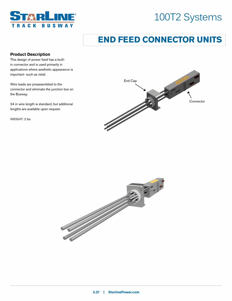
Product DescriptionThis design of power feed has a built-in connector and is used primarily in applications where aesthetic appearance is important- such as retail.
Wire leads are preassembled to the connector and eliminate the junction box on the Busway.
24 in wire length is standard, but additional lengths are available upon request.
2.37 | StarlinePower.com
100T2 Systems
END FEED CONNECTOR UNITS
End Cap
Connector
WEIGHT: 2 lbs
100T2 Systems
END FEED CONNECTOR UNITS: PRODUCT NUMBERS
2.38 | StarlinePower.com
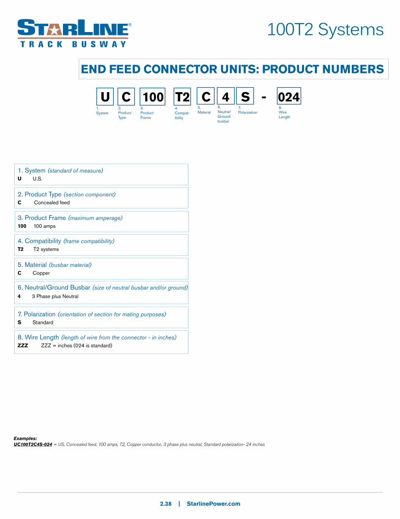
U C 100 T2 C 4 S - 024 1. System
2. Product Type
3. Product Frame
4. Compat-ibility
5.Material
6.Neutral/Ground busbar
7.Polarization
8. Wire Length
1. System (standard of measure)U U.S.
2. Product Type (section component)C Concealed feed
3. Product Frame (maximum amperage)100 100 amps
4. Compatibility (frame compatibility)T2 T2 systems
5. Material (busbar material)C Copper
6. Neutral/Ground Busbar (size of neutral busbar and/or ground)
7. Polarization (orientation of section for mating purposes)S Standard
8. Wire Length (length of wire from the connector - in inches)ZZZ ZZZ = inches (024 is standard)
4 3 Phase plus Neutral
Examples:UC100T2C4S-024 = US, Concealed feed, 100 amps, T2, Copper conductor, 3 phase plus neutral, Standard polarization- 24 inches
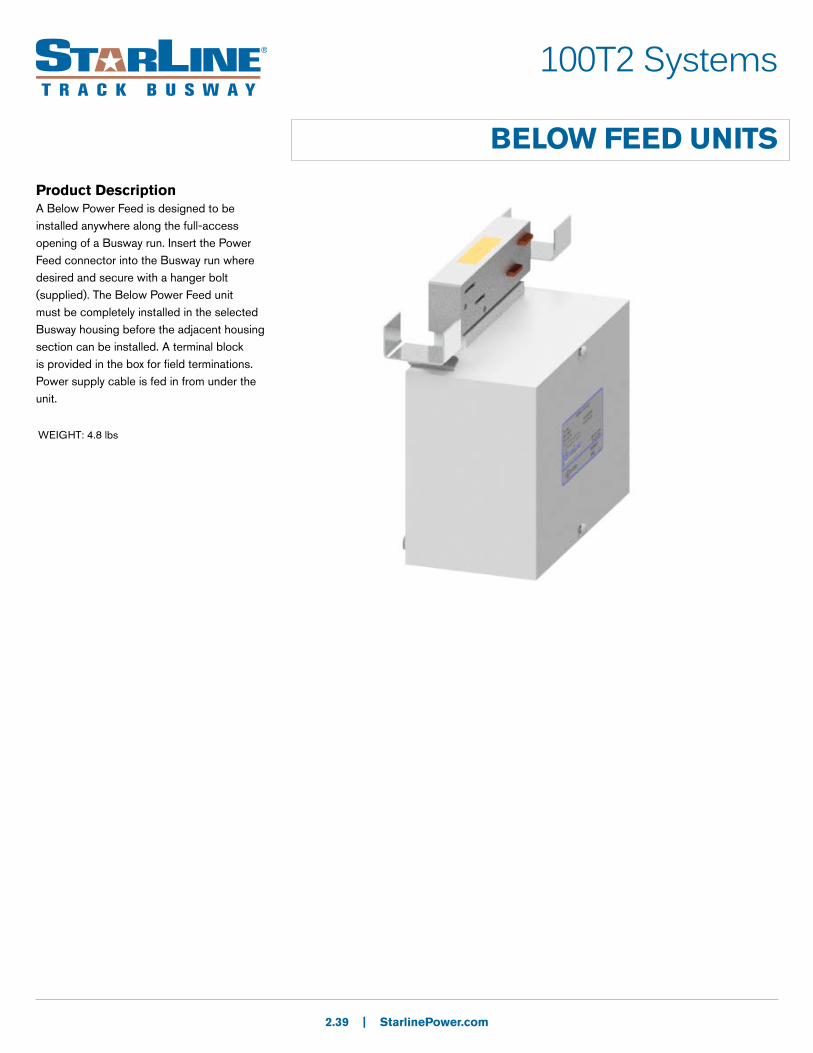
Product DescriptionA Below Power Feed is designed to be installed anywhere along the full-access opening of a Busway run. Insert the Power Feed connector into the Busway run where desired and secure with a hanger bolt (supplied). The Below Power Feed unit must be completely installed in the selected Busway housing before the adjacent housing section can be installed. A terminal block is provided in the box for field terminations. Power supply cable is fed in from under the unit.
2.39 | StarlinePower.com
100T2 Systems
BELOW FEED UNITS
WEIGHT: 4.8 lbs
100T2 Systems
BELOW FEED UNITS: PRODUCT NUMBERS
2.40 | StarlinePower.com
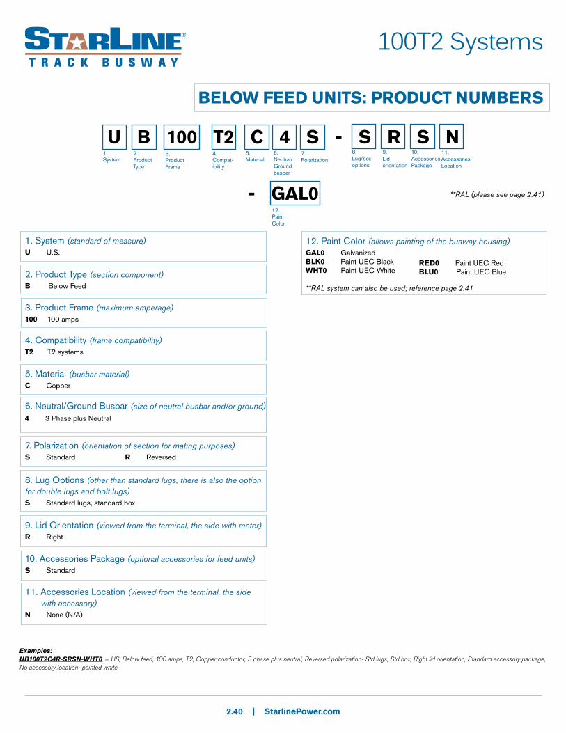
U B 100 T2 C 4 S - S R S N
- GAL0
1. System
2. Product Type
3. Product Frame
4. Compat-ibility
5.Material
6.Neutral/Ground busbar
7.Polarization
8. Lug/box options
9.Lid orientation
10.AccessoriesPackage
11.Accessories Location
1. System (standard of measure)U U.S.
2. Product Type (section component)B Below Feed
3. Product Frame (maximum amperage)100 100 amps
4. Compatibility (frame compatibility)T2 T2 systems
5. Material (busbar material)C Copper
6. Neutral/Ground Busbar (size of neutral busbar and/or ground)
7. Polarization (orientation of section for mating purposes)S Standard R Reversed
8. Lug Options (other than standard lugs, there is also the option for double lugs and bolt lugs)S Standard lugs, standard box
9. Lid Orientation (viewed from the terminal, the side with meter)R Right
10. Accessories Package (optional accessories for feed units)S Standard
4 3 Phase plus Neutral
12. Paint Color (allows painting of the busway housing)GAL0 Galvanized BLK0 Paint UEC BlackWHT0 Paint UEC White
**RAL system can also be used; reference page 2.41
RED0 Paint UEC RedBLU0 Paint UEC Blue
Examples:UB100T2C4R-SRSN-WHT0 = US, Below feed, 100 amps, T2, Copper conductor, 3 phase plus neutral, Reversed polarization- Std lugs, Std box, Right lid orientation, Standard accessory package, No accessory location- painted white
11. Accessories Location (viewed from the terminal, the side with accessory)N None (N/A)
**RAL (please see page 2.41)
12. Paint Color

| StarlinePower.com
RAL Colors
0 100
1 101
2 102
3 103
4 200
5 201
A 300
B 301
C 302
D 303
E 400
F 401
G 500
H 501
J 502
K 600
L 601
M 602
N 603
P 700
Q 701
R 702
S 703
T 704
U 800
V 801
W 802
X 900
Y 901
Z 902
0 0
1 1
2 2
3 3
4 4
5 5
6 6
7 7
8 8
9 9
2nd Character 3rd Character
Example:
P B 2 0 = Paint RAL 3012
1st Character
P Paint
T2 Series
2.41
4th Character
0 0

| StarlinePower.com
T2 Series
ACCESSORIES: SUPPORT HARDWARE
Threaded RodFor mounting to 3/8 - 16 threaded rod. Can be inserted anywhere along the top full-access slot of busway. Hanger support is required every 10 ft maximum.
Part Number URHB-3
Available in plain zinc or black (-BLK)
Weight .3 lb
3/8” rod coupler
StandardFor mounting to strut or other flat surfaces. Twist-in design allows inserting anywhere along the top full-access slot on the busway. Hanger support is required every 10 ft maximum.
Part NumberUTHB-3 (3/8”)
UTHB-1/4 (1/4”)
Available in plain zinc or black (-BLK)
Weight .2 lb
3/8” or 1/4” Stud
Weight HookCan be used as a hanger to suspend the Busway from chains or cables. Can also be used to hang loads of up to 50 lbs under the Busway, such as light fixtures, tools and balancers.
Part Number UWHRT2
Available in plain zinc
Weight .2 lb
2.42

| StarlinePower.com
T2 Series
ACCESSORIES: SUPPORT HARDWARE
2.43
Surface MountFor mounting to a surface. Comes with a 3/8 inch hole.
Part Number UMCT2-S (surface)
Available in all standard and RAL colors
T-Bar Suspended CeilingFor mounting to an inverted T-bar. The clip locks onto T-bar and the Busway is connected to the stud on the clip. T-bar is mounted with surface clip.
Part NumberUTHB-4
Available in plain zinc
Weight .1 lb
Recessed MountRecessed mount brackets are used when installing Busway that is recessed into a suspended ceiling.
*Hanger bolt must be ordered separately
Part NumberURMT2
Available in plain zinc
Weight .1 lb
CableFor mounting to a 1/16 in. or 3/32 in. aircraft cable with easy grip clamp assembly. Cable is not included. Hanger support is every 10 ft. maximum.
Part Number UACH-1 (1/16” cable)UACH-2 (3/32” cable)
Available in plain zinc
Weight .2 lb

| StarlinePower.com
T2 Series
ACCESSORIES: CONNECTION HARDWARE
End CapFor covering the end of 60T2 or 100T2 busway.
Part Number UECT2
Available in all standard and RAL colors
Weight: .2 lb
Optional Closure StripMade of white, rigid PVC, the closure strip is used to close the continuous access slot of the Busway. It may be used for aesthetic purposes, for keeping dust and dirt from entering the Busway or as an added safety measure. It is easily cut to length in the field to be installed around plug-in units.
Part NumberUCST2
Available in all standard colors
Maximum Cut Length: 20 ft
2.44
2.44”
1.83”
6”
Part NumberUJKT2-4
Available in all standard and RAL colors
Joint KitFor the connection of adjacent busway sections. Each kit is comprised of an in-line connector and housing coupler.
In-Line Connector: sections of Busway are joined electrically by means of an in-line connector. All in-line bus connectors are polarized to prevent phase mismatch.Housing Coupler: sections of Busway are joined mechanically by means of a housing coupler. One is required per connection point.
In-Line ConnectorThe connector is installed by inserting it into each end of the housing sections to be joined. Hex head compression screws are tightened to make a reliable connection.
Part NumberUBCT2-4
Housing CouplerHousing couplers make the mechanical connection between sections of Busway.
Part NumberUHCT2
Available in all standard and RAL colors
Universal Electric Corporation, manufacturer of STARLINE Track Busway, has been a global leader in power distribution since 1924. The company’s focus on innovation continues to pave the way for safer, more flexible and reliable electrical power distribution systems. Other STARLINE products include the Critical Power Monitor (CPM), which works in conjunction with STARLINE Track Busway to improve energy efficiency; Plug-In Raceway, the flexible, wall-mounted power distribution system; and DC Solutions, the revolutionary 380V direct current alternative for data centers.
168 Georgetown Rd. Canonsburg, PA 15317 800-245-6378 +1 724-597-7800 www.StarlinePower.com [email protected]
Most STARLINE systems and most standard components are UL, CE or ETL listed.
While every effort has been made to ensure the accuracy of all information, Universal Electric Corporation does not accept liability for any errors or omissions and reserves the right to
change information and descriptions of listed services and products.
REV 2


