20
Product Specification Design Team C, COMP 410 Spring 2016
| Date post: | 18-Jun-2018 |
| Category: |
Documents |
| Upload: | dangkhuong |
| View: | 213 times |
| Download: | 0 times |

Product Specification
Design Team C, COMP 410 Spring 2016
1. Introduction 1.1. Purpose This document defines the highlevel specifications and architecture of our system as well as the interactions between the system and and its users. The documentation is intended for developers of the system and the Customer. 1.2 Scope The Product will provide interfaces for the input of data regarding job requests and for assigning resources to be used to fulfill these job requests. The Product shall provide a means of estimating the cost of a job using specified resources during specified time intervals of use. The Product shall provide notifications to relevant parties concerning changes in job status such as delays or cancellations which may be caused by status updates concerning resources or evaluation of other data sources such as weather data obtained by sensors. These notifications may include updated cost estimates to relevant parties. The Product aims to enable schedulers of the Customer to track resource usage across job requests so that they may be efficiently rescheduled in a timely and costefficient manner as circumstances change. 1.3. Definitions, Acronyms, and Abbreviations
● Customer: Schlumberger and its associates. ● Product: The name of the product this document specifies. ● Client: The program, which usually has a GUI, which is used by an employee of the
Customer to interact with cloud services in welldefined ways. ● Job: A task which requires resources to have certain statuses (such as to be at certain
locations a given time) and other job dependencies to be satisfied. ● Job Request: A message sent in order to schedule a job. Includes where the job is and
what resources it requires as well as any job dependencies. ● Scheduled Job: The time and resources allocated to the job. Fulfills the requirements
of a job request. ● Job Status: Includes requested, scheduled, in progress, canceled, and completed. ● Job Dependency: A job that must be performed before another job. Dependencies
cannot be cyclic. ● Job Cost: A function determining the cost of a job assignment given scheduled
resources and scheduled dependent jobs. ● Resource: Anything a job needs to be completed that is managed by our system. Must
be identified by type. ● Resource Status: Includes location of a resource, information on the resource's
condition, and a time interval for which that information applies. ● Data Source: Sends environmental data to the cloud to inform analytics (ex: weather
sensor, updates in political status of regions).

● Constraint: A factor with a location and a time that affects when/if/at what cost a job can be scheduled
○ Under these two definitions, Data Sources and Resources are both Constraints. ○ Location and time connect the Constraints to the job requests and assignments. ○ Can also consider job dependencies to be Constraints.
● Query: Direct request for data from the cloud. Receives a single direct response from the Communication Hub.
● Communication Hub: Takes data and the clients to which it is to be sent, and relays the data to those clients.
● User Permissions: Permissions determine what actions a user can perform. Includes the permissions to change user permissions.
2. Overall Description 2.1 Product Perspective The Product is intended to be a largely selfcontained system. However any system which may interface with our system endpoints in the cloud for sending and receiving data shall be able to integrate into our system given appropriate user authentications. 2.2 User Characteristics Users of this system will be employees of the Customer (or its subsidiaries / clients / customers) who are using a program with a GUI (a Client). Depending on the user’s permissions, the user can be one or more of the following Client Types (which are defined in Section 2.2.1): Scheduler, Technical Specialist, Maintenance Worker, Resource Manager, System Administrator, Auditor. Sensors are a special type of Client (which may not have a GUI) that only send data. 2.2.1 Client Types A Client Type is uniquely defined by its permissions. Each Client Type has the same general set of permissions, but each user of a certain type can have specific, unique permissions granted to them by a System Administrator. For example, all Resource Manager can “update the status of resources”, but some Resource Managers might only have control over a certain type of resource and be unable to see or edit the status of all other resources in the system. Here are the possible Client Types:
● Scheduler Oversees a collection of well sites and schedules resources to fulfil job requests related to those well sites.
● Technical Specialist Can diagnose a technical issue at a well site and requests jobs to be done based on that issue.
● Maintenance Worker A worker that is required for the completion of a maintenance job at a well site. Is assigned jobs based on their expertise.

● Resource Manager Knows the status of resources (e.g. trucks) needed for maintenance jobs. Registers new resources and updates the status of those resources.
● Sensor Senses aspects of the environment (e.g. weather). ● System Administrator Knows about all the users of the system and the permissions
that they currently have. Can add and remove users and update their permissions. Can add additional, custom Client Types to this list and grant them permissions.
● Auditor Oversees the scheduling process. Looks at historical data about scheduling decisions that were made.
Note that this list is not comprehensive, as System Administrators can create custom Client Types. 2.3. Product Functions
● Receiving and storing job requests from Schlumberger and clients all over the world. ● Realtime monitoring of weather or political status near production sites and other
external risk factors that may affect production. ● Keeping track of properties and inventories for Schlumberger and clients. ● Realtime analyses of risk factors and inventories to produce an optimal plan for
allocating resources for a job request and automatically notify relevant personnel. ● Providing a means of authentication to distinguish between user permissions to provide
segregation of data and actions.
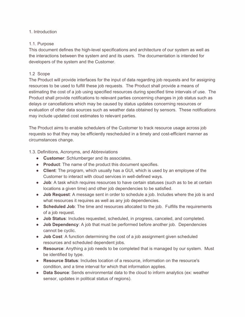
2.4. Use Cases 2.4.1 Use Case 1 Login/Logout Use Case Diagram:
Brief Description In order to access any data in the system or make a request, all users must login. When they are done, they should logout. StepbyStep Description Scenario 1: Logging in to the product
1. When the user first launches the product, they will be asked to provide their ID and password.
2. The system check the user’s permissions associated with the ID. 3. If the login information is incorrect, the user will be prompted to reenter their
information. 4. If the login information provided is correct, the user will be shown the GUI
corresponding to their role in the system. Scenario 2: Logging out of the product
1. The user clicks logout when they are finished.

2.4.2 Use Case 2 Scheduler Use Case Diagram
Brief Description In our current view, the scheduler is a human user of the Product. However, in the future the scheduler will become part of the Product as a client that exists in the cloud. The scheduler responds to user’s requests for new jobs to create job assignments. If the status of a job is affected by a changing constraint, the job will be rescheduled. StepbyStep Description Before this use case can begin, the scheduler must already be logged in. Scenario 1: Scheduling a new job request
1. The scheduler queries for an unfulfilled job request. 2. The scheduler queries to resolve the constraints of the job, such as resources, labor,
and good weather. 3. The system displays the possible resources that could be used to complete the job
and when the weather permits the job to be done. 4. The scheduler creates a job assignment, allocating resources, choosing a time for
the job to be completed, and calculating the cost of the job. 5. The new job assignment is stored in the database.
Scenario 2: Updating a job 1. The scheduler receives an update on a constraint for one of the jobs it scheduled
previously. 2. The scheduler queries to resolve the constraints of the job, such as resources, labor,
and good weather so it can be rescheduled.

3. The system displays the possible resources that could be used to complete the job and when the weather permits the job to be done.
4. The scheduler creates a new job assignment, allocating resources, choosing a time for the job to be completed, and calculating the cost of the job.
5. The new job assignment is stored in the database. 2.4.3 Use Case 3 Technical Specialist Use Case Diagram
Brief Description The technical specialist creates job requests when maintenance is needed. StepbyStep Description Before this use case can begin, the technical specialist must already be logged in. Scenario 1: Make a job request
1. After analyzing a problem, the technical specialist chooses to create a new job. 2. The system displays a form containing information about the job, such as the user,
time, location, problem, resources needed, etc. 3. The job requests is sent to the system. 4. The system stores the job requests in the database, and sends it to the scheduler.
Scenario 2: Request job status 1. The technical specialist uses the GUI to view the status of one of the jobs they
initiated. 2. The system shows all the jobs created by this specialists, with the possibility of
filtering the results. 3. The technical specialist chooses one of their jobs. 4. The system retrieve data about this job from the database.

2.4.4 Use Case 4 Maintenance Worker Use Case Diagram
Brief Description Once a job is scheduled or rescheduled, the system will send notifications to all workers assigned to that job. StepbyStep Description Before this use case can begin, the maintenance worker must already be logged in. Scenario 1: A worker is assigned to a new job
1. The scheduler assigns a worker to an incoming job request. 2. The worker receives a notification about the new job.
Scenario 2: The status of a job a worker is assigned to changes 1. Incoming data causes the status of a job to change. 2. All workers assigned to that job are notified about the change in status.
Scenario 2: The worker’s status changes. 1. The worker sends their updated status to the cloud. 2. The cloud stores the updated status reevaluates any jobs the worker was assigned to.

2.4.5 Use Case 5 Resource Manager Use Case Diagram
Brief Description A resource manager is in charge of maintaining a collection of resources, which are anything a job needs to be completed. This includes workers and physical parts. StepbyStep Description Before this use case can begin, the resource manager must already be logged in. Scenario 1: Registering a new resource
1. The resource manager uses the GUI to choose to add a new resource. 2. The system displays the form for the manager to provide pertinent information, such
as type and quantity. 3. The system stores the new resource into the database.
Scenario 2: Updating a new resource 1. The resource manager uses the GUI to choose to update one of their existing
resources. 2. The system displays the resources owned by that manager. 3. The resource manager chooses the resource to update. 4. The system displays a form to update a field pertaining to that resource or remove
the resource from the system. 5. The system stores the updated information into the database.

2.4.6 Use Case 6 Data Source Use Case Diagram
Brief Description A data source transmits data to the Product. This could be information pertaining to the weather at a specific location or the status of an oilwell. Any users of the system affected by a change based on the input data will be notified. StepbyStep Description Before this use case can begin, the data source must be registered with the system.
1. The data source intermittently sends data to system. 2. The system stores this information in the database and does any processing
necessary. For example, weather data will be analyzed to assist in making predictions.
3. Any resources or jobs affected by the status change will be notified accordingly.

2.4.7 Use Case 7 System Administrator Use Case Diagram
Brief Description A system administrator manages the users of the Product. StepbyStep Description Before any of these scenarios can begin, the administrator must be logged in to the Product. Scenario 1: Adding a user to the system
1. The system administrator uses the GUI to choose to add a new user to the system. 2. The system displays the form for the administrator to add the pertinent information,
such as name, job, and permissions. 3. The system stores the new user in the database.
Scenario 2: Removing a user from the system 1. The system administrator uses the GUI to choose to remove a user from the system. 2. The administrator queries for the user. 3. The system removes the user from the database.
Scenario 3: Updating a user from the system. 1. The system administrator uses the GUI to choose to update an existing user of the
Product. 2. The administrator queries for the user. 3. The system displays a form to update information about the selected user. 4. The system updates the user in the database.
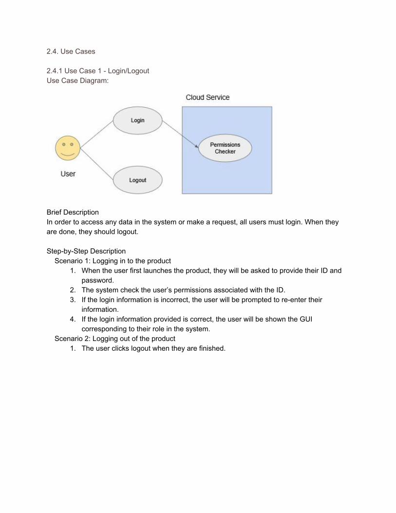
2.4.8 Use Case 8 Auditor Use Case Diagram
Brief Description An auditor can query the system for information, both real time and historical, in order to stay updated on the status of the Product and the decisions that were made in the past. StepbyStep Description Before any of these scenarios can begin, the auditor must be logged in to the Product.
1. The auditor uses the GUI to choose to query information from the database. 2. The auditor selects the type of information they are interested in, and a query is
developed based on their search parameters. 3. The system retrieves data from the database. 4. The data is displayed to the auditor.
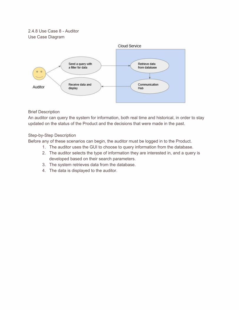
2.4.8 Combined Use Case The use cases shown above can be described by a few general uses: sending a query for data stored in the system (and receiving the results of that query), sending data to the cloud to be processed, and receiving notifications about data that one is affected by.
Brief Description The client and the cloud communicate by sending messages. The messages sent by the client cause the desired actions to be carried out on the cloud and the messages sent by the cloud provide the client with important data. StepbyStep Description
1. A client sends the cloud containing either data to be processed or a query for data. 2. Based on the type of message it received, the cloud either stores and processes the
data it was sent or queries the database. 3. The cloud sends messages through the communication hub to all the clients affected by
its actions. In the case of a query, this should just be the user that made the query. When data is changed, such as information about a resource, many clients may be affected and they are all notified.
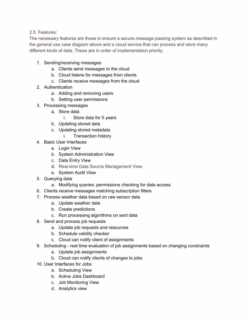
2.5. Features: The necessary features are those to ensure a secure message passing system as described in the general use case diagram above and a cloud service that can process and store many different kinds of data. These are in order of implementation priority.
1. Sending/receiving messages a. Clients send messages to the cloud b. Cloud listens for messages from clients c. Clients receive messages from the cloud
2. Authentication a. Adding and removing users b. Setting user permissions
3. Processing messages a. Store data
i. Store data for 5 years b. Updating stored data c. Updating stored metadata
i. Transaction history 4. Basic User Interfaces
a. Login View b. System Administration View c. Data Entry View d. Realtime Data Source Management View e. System Audit View
5. Querying data a. Modifying queries: permissions checking for data access
6. Clients receive messages matching subscription filters 7. Process weather data based on raw sensor data
a. Update weather data b. Create predictions c. Run processing algorithms on sent data
8. Send and process job requests a. Update job requests and resources b. Schedule validity checker c. Cloud can notify client of assignments
9. Scheduling real time evaluation of job assignments based on changing constraints a. Update job assignments b. Cloud can notify clients of changes to jobs
10. User Interfaces for Jobs a. Scheduling View b. Active Jobs Dashboard c. Job Monitoring View d. Analytics view

2.5.1 System Interfaces For the initial version, the Product is a selfcontained system. 2.5.2 User Interfaces All clients except for Sensors have access to the Login view (Sensors are registered/logged in by an authorized user).
● Login View ○ Authenticate/Deauthenticate a user.
As noted in Section 2.2.1, A client type is defined by its permissions. Except for Sensors, all clients of a certain type have access to one or more of the following views:
● Active Jobs Dashboard ○ View the list of jobs subscribed to. ○ Access (based on permissions) other views.
● Data Entry View ○ Creation of a new resource. ○ Update a resource’s status (includes workers updating their own status). ○ Update a resource’s metadata. ○ Creation of a new data source. ○ Update data source status. ○ Update data source metadata.
● Realtime Data Source Management View ○ View a resource and its status. ○ View data source data, metadata, and status. ○ View predictions of conditions at a location.
● Scheduling View ○ Receive job requests. ○ Creation of a new, scheduled job. ○ Modify a previously scheduled job. ○ Remove a scheduled job from the system.
● Job Requesting View ○ Creation of a new job request. ○ Receive notifications for the changes in status of requested jobs.
● Job Monitoring View ○ View a scheduled job and its status. ○ Receive job subscriptions. ○ Accept or reject job subscriptions. ○ Receive notifications for changes in the job statuses of jobs subscribed to.
● Analytics View ○ View information about the analytics being used. ○ Update analytics algorithm or parameters.
● System Administration View ○ Register/Remove a new user. ○ Update user metadata. ○ Add/Remove a permission and capability. ○ Add/Remove a group. ○ Add/Remove permissions to a group or user.
● System Audit View ○ View historical event record of a job. ○ View historical event record of a resource. ○ View historical event record of a data source. ○ View historical event record of a user’s actions. ○ View analytics of historical data.
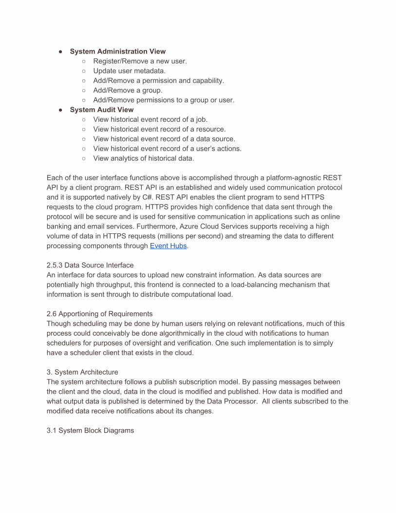
Each of the user interface functions above is accomplished through a platformagnostic REST API by a client program. REST API is an established and widely used communication protocol and it is supported natively by C#. REST API enables the client program to send HTTPS requests to the cloud program. HTTPS provides high confidence that data sent through the protocol will be secure and is used for sensitive communication in applications such as online banking and email services. Furthermore, Azure Cloud Services supports receiving a high volume of data in HTTPS requests (millions per second) and streaming the data to different processing components through Event Hubs. 2.5.3 Data Source Interface An interface for data sources to upload new constraint information. As data sources are potentially high throughput, this frontend is connected to a loadbalancing mechanism that information is sent through to distribute computational load. 2.6 Apportioning of Requirements Though scheduling may be done by human users relying on relevant notifications, much of this process could conceivably be done algorithmically in the cloud with notifications to human schedulers for purposes of oversight and verification. One such implementation is to simply have a scheduler client that exists in the cloud. 3. System Architecture The system architecture follows a publish subscription model. By passing messages between the client and the cloud, data in the cloud is modified and published. How data is modified and what output data is published is determined by the Data Processor. All clients subscribed to the modified data receive notifications about its changes. 3.1 System Block Diagrams
Different users will have different GUIs with their appropriate actions enabled. Data entry actions create a data message, encapsulate it in an HTTPS request, and send it to the cloud to be processed. Query actions create a query message, put it in an HTTPS request and send it to the cloud. The requested data is sent back by the cloud in a separate request.

Lines: Red = new data to the system (registering a new sensor, adding a new user, adding a scheduled job) Pink = Updating existing data (new raw weather data) Green = Respond to a query Black = common to all types of data Boxes: Yellow = worker role Gray = Cloud entry point that accepts HTTPS requests Red = Client application 1. The client sends a message to the cloud entry point in an HTTPS request. 2. Web role sends message queue(s) for sent data messages 3. The message is processed based on type and content and forwarded to the appropriate
processing 4. Add an entry for the new data into the database 5. If necessary, add dependencies by making existing data dependent on the new data. 6. Change the status of stored data in response to the incoming data update. 7. Figure out which data is dependent on the data whose status was updated. 8. Iteratively update data statuses and find dependents until the users who are affected by
the data change are found. 9. Change the status of the data in the database. 10. Send a message to the communication hub to forward to the clients who are dependent
on the data that changed. 11. Send the results of the user’s query to the communication hub to be forwarded to the
user. 12. Client receives notifications from the communication hub in direct response to messages

or based on data they are dependent on. All the worker role components (yellow boxes in the diagram above) shall be capable of deployment independent of the rest of the system. This allows for new or modified data processing algorithms to be deployed while the larger system still continues to function. Furthermore, multiples of each worker role could be spun up for load balancing, allowing for each process to scale at different rates. All client messages can be processed in parallel by the separate worker roles allowing the system to handle high volumes of incoming data. More explanation of data dependency: All data (except metadata) is a node in a data dependency graph. In the case that new raw data effects a tree of related data, all the data is updated down to the affected clients. For example, raw weather data at one location may affect predictions of the weather at a few well sites and each well site may have a few jobs scheduled at it that day. If the prediction is for a hurricane, all the affected job statuses will be updated and all users that are dependent on those jobs will be notified through the communication hub. Clients that may be dependent on a job are:
1. The client that sent the job request. 2. The client that sent the scheduled job 3. Any maintenance worker who is assigned to the job. 4. Any resource manager whose resource is assigned to the job. 5. Other relations are possible and can be added.
A client and a job’s relationship are defined when the job is requested or scheduled. When a job is requested, the client who requested it is made dependent to that job. When a job is scheduled, the scheduler (if human) and all the workers and resource managers assigned to that job are made dependent to it as well. Whenever a job status changes, all the workers who are dependent on that job are notified. Note that an automated scheduler could be created as a new client, and integrate seamlessly into the current system. An automated scheduler could also potentially be added as a new node type in the cloud without changing much of the system semantics.
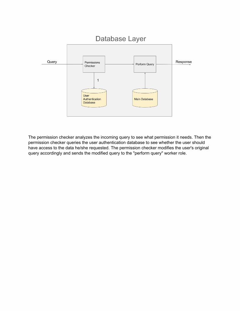
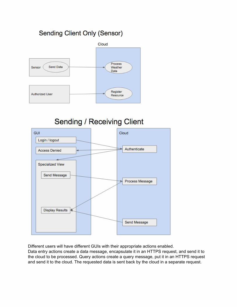
The permission checker analyzes the incoming query to see what permission it needs. Then the permission checker queries the user authentication database to see whether the user should have access to the data he/she requested. The permission checker modifies the user's original query accordingly and sends the modified query to the "perform query" worker role.


