2 Product Specification S4Cplus M2000/BaseWare OS 4.0
Description
1 Description
1.1 Structure
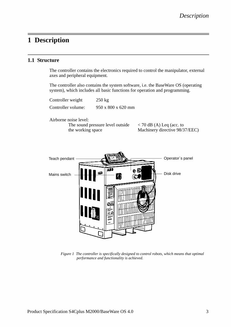
The controller contains the electronics required to control the manipulator, external axes and peripheral equipment.
The controller also contains the system software, i.e. the BaseWare OS (operating system), which includes all basic functions for operation and programming.
Controller weight 250 kg
Controller volume: 950 x 800 x 620 mm
Airborne noise level:The sound pressure level outside < 70 dB (A) Leq (acc. tothe working space Machinery directive 98/37/EEC)
Figure 1 The controller is specifically designed to control robots, which means that optimal performance and functionality is achieved.
Teach pendant Operator´s panel
Disk driveMains switch
Product Specification S4Cplus M2000/BaseWare OS 4.0 3
Description
Figure 2 View of the controller from the front, from above and from the side (dimensions in mm).
200
950980 *
500
500
820
Lifting points * Castor wheels, Option 126
800
250
Extended cover
Option 123
Cabinet extension
Option 124
for forklift
200
Air distance to wall
800
623
71 52
4 Product Specification S4Cplus M2000/BaseWare OS 4.0
Description
1.2 Safety/Standards
The robot conforms to the following standards:
EN 292-1 Safety of machinery, terminology
EN 292-2 Safety of machinery, technical specifications
EN 954-1 Safety of machinery, safety related parts of control systems
EN 60204 Electrical equipment of industrial machines
IEC 204-1 Electrical equipment of industrial machines
ISO 10218, EN 775 Manipulating industrial robots, safety
ISO 9787 Manipulating industrial robots, coordinate systems and motions
IEC 529 Degrees of protection provided by enclosures
EN 50081-2 EMC, Generic emission
EN 61000-6-2 EMC, Generic immunity
ANSI/UL 1740-1996 (option) Standard for Industrial Robots and Robotic Equipment
CAN/CSA Z 434-94 (option) Industrial Robots and Robot Systems - General Safety Requirements
The robot complies fully with the health and safety standards specified in the EEC’s Machinery Directives.
The robot controller is designed with absolute safety in mind. It has a dedicated safety system based on a two-channel circuit which is monitored continuously. If any component fails, the electrical power supplied to the motors shuts off and the brakes engage.
Safety category 3Malfunction of a single component, such as a sticking relay, will be detected at the next MOTOR OFF/MOTOR ON operation. MOTOR ON is then prevented and the faulty section is indicated. This complies with category 3 of EN 954-1, Safety of machinery - safety related parts of control systems - Part 1.
Selecting the operating mode The robot can be operated either manually or automatically. In manual mode, the robot can only be operated via the teach pendant, i.e. not by any external equipment.
Reduced speedIn manual mode, the speed is limited to a maximum of 250 mm/s (600 inch/min.).The speed limitation applies not only to the TCP (Tool Centre point), but to all parts of the robot. It is also possible to monitor the speed of equipment mounted on the robot.
Three position enabling deviceThe enabling device on the teach pendant must be used to move the robot when in manual mode. The enabling device consists of a switch with three positions, meaning that all robot movements stop when either the enabling device is pushed fully in, or when it is released completely. This makes the robot safer to operate.
Product Specification S4Cplus M2000/BaseWare OS 4.0 5
Description
Safe manual movementThe robot is moved using a joystick instead of the operator having to look at the teach pendant to find the right key.
Over-speed protectionThe speed of the robot is monitored by two independent computers.
Emergency stopThere is one emergency stop push button on the controller and another on the teach pendant. Additional emergency stop buttons can be connected to the robot’s safety chain circuit.
Safeguarded space stopThe controller has a number of electrical inputs which can be used to connect external safety equipment, such as safety gates and light curtains. This allows the robot’s safety functions to be activated both by peripheral equipment and by the robot itself.
Delayed safeguarded space stopA delayed stop gives a smooth stop. The robot stops in the same way as at a normal program stop with no deviation from the programmed path. After approx. 1 second the power supplied to the motors shuts off.
Collision detectionIn case an unexpected mechanical disturbance like a collision, electrode sticking, etc. occurs, the robot will stop and slightly back off from its stop position.
Restricting the working space The movement of each axis can be restricted using software limits. There are safeguarded space stops for connection of limit switches to restrict the working space.For some robots the axes 1-3 can also be restricted by means of mechanical stops.
Hold-to-run control“Hold-to-run” means that you must depress the start button in order to move the robot. When the button is released the robot will stop. The hold-to-run function makes program testing safer.
Fire safetyBoth the manipulator and control system comply with UL’s (Underwriters Laboratory) tough requirements for fire safety.
Safety lampAs an option, the robot can be equipped with a safety lamp mounted on the manipulator. This is activated when the controller is in the MOTORS ON state.
6 Product Specification S4Cplus M2000/BaseWare OS 4.0
Description
Product Specification S4Cplus M2000/BaseWare OS 4.0 7
1.3 Operation
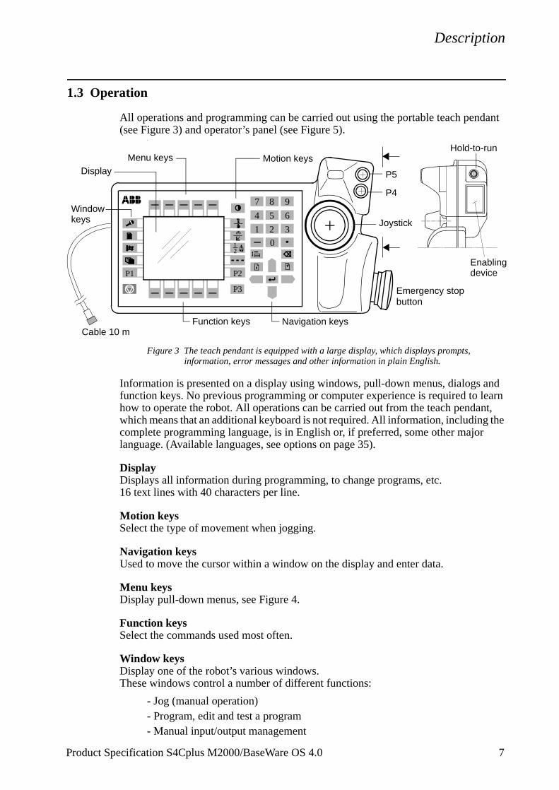
All operations and programming can be carried out using the portable teach pendant (see Figure 3) and operator’s panel (see Figure 5).
.
Figure 3 The teach pendant is equipped with a large display, which displays prompts, information, error messages and other information in plain English.
Information is presented on a display using windows, pull-down menus, dialogs and function keys. No previous programming or computer experience is required to learn how to operate the robot. All operations can be carried out from the teach pendant, which means that an additional keyboard is not required. All information, including the complete programming language, is in English or, if preferred, some other major language. (Available languages, see options on page 35).
DisplayDisplays all information during programming, to change programs, etc.16 text lines with 40 characters per line.
Motion keysSelect the type of movement when jogging.
Navigation keysUsed to move the cursor within a window on the display and enter data.
Menu keysDisplay pull-down menus, see Figure 4.
Function keysSelect the commands used most often.
Window keysDisplay one of the robot’s various windows. These windows control a number of different functions:
- Jog (manual operation)- Program, edit and test a program- Manual input/output management
21
2 3
0
1
4 5 6
7 8 9
P3
P1 P2
Hold-to-run
Enabling
P4
P5
device
Joystick
Function keys
Motion keysMenu keys
Window
Navigation keys
Display
keys
Cable 10 m
Emergency stop button
Description
8 Product Specification S4Cplus M2000/BaseWare OS 4.0
- File management- System configuration- Service and troubleshooting- Automatic operation
User-defined keys (P1-P5) Five user-defined keys that can be configured to set or reset an output (e.g. open/close gripper) or to activate a system input.
Hold-to-runA push button which must be pressed when running the program in manual mode with full speed.
Enabling deviceA push button which, when pressed halfway in, takes the system to MOTORS ON. When the enabling device is released or pushed all the way in, the robot is taken to the MOTORS OFF state.
JoystickThe joystick is used to jog (move) the robot manually; e.g. when programming the robot.
Emergency stop buttonThe robot stops immediately when the button is pressed in.
Figure 4 Window for manual operation of input and output signals.
Using the joystick, the robot can be manually jogged (moved). The user determines the speed of this movement; large deflections of the joystick will move the robot quickly, smaller deflections will move it more slowly.
The robot supports different user tasks, with dedicated windows for:
- Production
Inputs/Outputs
File
Value
10101113
Edit View
1 0
4(6)Name
di1di2grip1grip2clamp3Bfeederprogno
1 Goto ...2 Goto Top3 Goto Bottom
Menu keys
I/O list
Menu
Line indicator
Cursor
Function keys
Description
- Programming
- System setup
- Service and installation
Operator’s panel
Figure 5 The operating mode is selected using the operator’s panel on the controller.
Operating mode selector
MOTORS ON Continuous light
Fast flashing light (4Hz)
Ready for program execution
Note: The motors have been switched on
=
= One of the safeguarded space stops is active
Emergency stopIf pressed in,
MOTORS ON buttonand indicating lamp
Duty time counter
The robot is not calibrated or the revolution counters
Slow flashing light (1 Hz)Note: The motors have been switched off
Indicates the operating time for the manipulator (released brakes)
Operating mode selector
Automatic mode
Manual modeat reduced speed
100% Manual modeat full speed
= Running production
Programming and setupMax. speed 250 mm/s (600 inches/min.)
=
Optional:
Testing at full program speed=
are not updated
pull to release
=
Using a key switch, the robot can be locked in two (or three)different operating modes depending on chosen mode selector:
Equipped with this mode,the robot is not approvedaccording to ANSI/UL
Product Specification S4Cplus M2000/BaseWare OS 4.0 9
Description
10 Product Specification S4Cplus M2000/BaseWare OS 4.0
Both the operator’s panel and the teach pendant can be mounted externally, i.e. separated from the cabinet. The robot can then be controlled from there.
The robot can be remotely controlled from a computer, PLC or from a customer’s panel, using serial communication or digital system signals.
For more information on how to operate the robot, see the User’s Guide.
Description
1.4 Memory
Available memory
The controller has two different memories:
- a fixed DRAM memory of size 32 MB, used as working memory- a flash disk memory, standard 64 MB, used as mass memory. Optional 128 MB.
The DRAM memory is used for running the system software and the user programs and it is thus divided into three areas:
- system software- system software execution data- user RAPID programs, about 5.5 MB, see Figure 6 (when installing different
options, the user program memory will decrease, at most by about 0.7 MB).
The flash disk is divided into four main areas:
- a base area of 5 MB, with permanent code for booting- a release area of 20 MB, where all the code for a specific release is stored- a system specific data area of 10 MB, where all the run time specific data
including the user program for a system is stored at backup- a user mass memory area which can be used for storing RAPID programs, data,
logs etc.
The flash disk is used for backup, i.e. when a power failure occurs or at power off, all the system specific data including the user program, see Figure 6, will be stored on the flash disk and restored at power on. A backup power system (UPS) ensures the automatic storage function.
Figure 6 Available memory.
DRAM memory32 MB
Flash disk memory64/128 MB
Boot 5 MB
Release storage20 MB
System data anduser program10 MB
Mass memory areaavailable for
Systemsoft ware
Data
User RAPIDprogram 5.5 MB
the user
Power on -restore
Power off -store
Product Specification S4Cplus M2000/BaseWare OS 4.0 11
Description
Several different systems, i.e. process applications, may be installed at the same time in the controller, of which one can be active. Each such application will occupy another 10 MB of the flash memory for system data. The release storage area will be in common as long as the process applications are based on the same release. If two different releases should be loaded, the release storage area must also be doubled.
For RAPID memory consumption, see RAPID Developer’s Manual. As an example, a MoveL or MoveJ instruction consumes 236 bytes when the robtarget is stored in the instruction (marked with ‘*’) and 168 bytes if a named robtarget is used. In the latter case, the CONST declaration of the named robtarget consumes an additional 280 bytes.
Additional software options will reduce the available user program memory, most of them however only marginally, i.e. the user program area will still be about 5.5 MB. Only the SpotWare option will reduce memory significantly, i.e. down to about 4.8 MB depending on the number of simultaneous welding guns.
1.5 Installation
The controller is delivered with a standard configuration for the corresponding manipulator, and can be operated immediately after installation. Its configuration is displayed in plain language and can easily be changed using the teach pendant.
Explosive environmentsThe controller must not be located or operated in an explosive environment.
Ambient temperatureController during operation +5oC (41oF) to +45oC (113oF)with option 473 +52oC (125oF)Controller during transportation and storage, -25oC (13oF) to +42oC (107oF)for short periods (not exceeding 24 hours) up to +70oC (158oF)
Relative humidityTransportation, storage and operation Max. 95% at constant temperature
VibrationController during transportation and storage 10-55 Hz: Max. ±0.15 mm
55-150 Hz: Max. 20 m/s2
BumpsController during transportation and storage Max. 100 m/s2 (4-7 ms)
Power supply
Mains voltage 200-600 V, 3p (3p + N for certain options
Mains voltage tolerance +10%,-15%
Mains frequency 48.5 to 61.8 Hz
12 Product Specification S4Cplus M2000/BaseWare OS 4.0
Computer system backup capacity 20 sec (rechargeable battery)at power interrupt
Configuration
The robot is very flexible and can, by using the teach pendant, easily be configured to suit the needs of each user:
Authorisation Password protection for configuration and program window
Most common I/O User-defined lists of I/O signalsInstruction pick list User-defined set of instructionsInstruction builder User-defined instructionsOperator dialogs Customised operator dialogsLanguage All text on the teach pendant can be displayed in
several languagesDate and time Calendar supportPower on sequence Action taken when the power is switched onEM stop sequence Action taken at an emergency stopMain start sequence Action taken when the program is
starting from the beginningProgram start sequence Action taken at program startProgram stop sequence Action taken at program stopChange program sequence Action taken when a new program is loadedWorking space Working space limitationsExternal axes Number, type, common drive unit, mechanical
unitsBrake delay time Time before brakes are engagedI/O signal Logical names of boards and signals, I/O mapping,
cross connections, polarity, scaling, default value at start up, interrupts, group I/O
Serial communication Configuration
For a detailed description of the installation procedure, see the Product Manual - Installation and Commissioning.
1.6 Programming
Programming the robot involves choosing instructions and arguments from lists of appropriate alternatives. Users do not need to remember the format of instructions, since they are prompted in plain English. “See and pick” is used instead of “remember and type”.
1. Enlarged transformer for external axes
Product Specification S4Cplus M2000/BaseWare OS 4.0 13
Description
The programming environment can be easily customized using the teach pendant.
- Shop floor language can be used to name programs, signals, counters, etc.
- New instructions can be easily written.
- The most common instructions can be collected in easy-to-use pick lists.
- Positions, registers, tool data, or other data, can be created.
Programs, parts of programs and any modifications can be tested immediately without having to translate (compile) the program.
Movements
A sequence of movements is programmed as a number of partial movements between the positions to which you want the robot to move.
The end position of a movement is selected either by manually jogging the robot to the desired position with the joystick, or by referring to a previously defined position.
The exact position can be defined (see Figure 7) as:
- a stop point, i.e. the robot reaches the programmed position
or
- a fly-by point, i.e. the robot passes close to the programmed position. The size of the deviation is defined independently for the TCP, the tool orientation and the external axes.
Figure 7 The fly-by point reduces the cycle time since the robot does not have to stop atthe programmed point. The path is speed independent.
The velocity may be specified in the following units:
- mm/s - seconds (time it takes to reach the next programmed position)- degrees/s (for reorientation of the tool or for rotation of an external axis)
Program management
For convenience, the programs can be named and stored in different directories.
The mass memory can also be used for program storage. These can then be automatically downloaded using a program instruction. The complete program or parts of programs can be transferred to/from the network or a diskette.
The program is stored as a normal PC text file, which means that it can be edited using
Stop point Fly-by pointUser-definable distance (in mm)
14 Product Specification S4Cplus M2000/BaseWare OS 4.0
Description
a standard PC.
Editing programs
Programs can be edited using standard editing commands, i.e. “cut-and-paste”, copy, delete, find and change, undo etc. Individual arguments in an instruction can also be edited using these commands.
No reprogramming is necessary when processing left-hand and right-hand parts, since the program can be mirrored in any plane.
A robot position can easily be changed either by
- jogging the robot with the joystick to a new position and then pressing the “ModPos” key (this registers the new position)
or by
- entering or modifying numeric values.
To prevent unauthorised personnel from making program changes, passwords can be used.
Testing programs
Several helpful functions can be used when testing programs. For example, it is possible to
- start from any instruction- execute an incomplete program- run a single cycle- execute forward/backward step-by-step - simulate wait conditions- temporarily reduce the speed- change a position- tune (displace) a position during program execution.
For more information, see the User’s Guide and RAPID Reference Manual.
1.7 Automatic Operation
A dedicated production window with commands and information required by the operator is automatically displayed during automatic operation.
The operation procedure can be customised to suit the robot installation by means of user-defined operating dialogs.
Product Specification S4Cplus M2000/BaseWare OS 4.0 15
Description
16 Product Specification S4Cplus M2000/BaseWare OS 4.0
Figure 8 The operator dialogs can be easily customised.
A special input can be set to order the robot to go to a service position. After service, the robot is ordered to return to the programmed path and continue program execution.
You can also create special routines that will be automatically executed when the power is switched on, at program start and on other occasions. This allows you to customise each installation and to make sure that the robot is started up in a controlled way.
The robot is equipped with absolute measurement, making it possible to operate the robot directly when the power is switched on. For your convenience, the robot saves the used path, program data and configuration parameters so that the program can be easily restarted from where you left off. Digital outputs are also set automatically to the value prior to the power failure.
1.8 The RAPID Language and Environment
The RAPID language is a well balanced combination of simplicity, flexibility and powerfulness. It contains the following concepts:
- Hierarchical and modular program structure to support structured programming and reuse.
- Routines can be Functions or Procedures.
- Local or global data and routines.
- Data typing, including structured and array data types.
- User defined names (shop floor language) on variables, routines and I/O.
- Extensive program flow control.
- Arithmetic and logical expressions.
- Interrupt handling.
- Error handling (for exception handling in general, see Exception handling).
- User defined instructions (appear as an inherent part of the system).
- Backward handler (user definition of how a procedure should behave when stepping backwards).
- Many powerful built-in functions, e.g mathematics and robot specific.
- Unlimited language (no max. number of variables etc., only memory limited).
Windows based man machine interface with built-in RAPID support (e.g. user defined pick lists).
Front A Front B Front C Other Service
Select program to run:
Description
1.9 Exception handling
Many advanced features are available to make fast error recovery possible. Characteristic is that the error recovery features are easy to adapt to a specific installation in order to minimise down time. Examples:
- Error Handlers (automatic recovery often possible without stopping production).
- Restart on Path.
- Power failure restart.
- Service routines.
- Error messages: plain text with remedy suggestions, user defined messages.
- Diagnostic tests.
- Event logging.
1.10 Maintenance and Troubleshooting
The controller requires only a minimum of maintenance during operation. It has been designed to make it as easy to service as possible:
- The controller is enclosed, which means that the electronic circuitry is protected when operating in a normal workshop environment.
- There is a supervision of temperature, fans and battery health.
The robot has several functions to provide efficient diagnostics and error reports:
- It performs a self-test when power on is set.
- Computer status LEDs and console (serial channel) for fault tracing support.
- Errors are indicated by a message displayed in plain language. The message includes the reason for the fault and suggests recovery action.
- Faults and major events are logged and time-stamped. This makes it possible to detect error chains and provides the background for any downtime. The log can be read on the teach pendant display, stored in a file or printed on a printer.
- There are commands and service programs in RAPID to test units and functions.
- LEDs on the panel unit indicate status of the safeguarded switches.
Most errors detected by the user program can also be reported to and handled by the standard error system. Error messages and recovery procedures are displayed in plain language.
For detailed information on maintenance procedures, see Maintenance section in the Product Manual.
Product Specification S4Cplus M2000/BaseWare OS 4.0 17
Description
18 Product Specification S4Cplus M2000/BaseWare OS 4.0
1.11 Robot Motion
Motion concepts
QuickMoveTM
The QuickMoveTM concept means that a self-optimizing motion control is used. The robot automatically optimizes the servo parameters to achieve the best possible performance throughout the cycle - based on load properties, location in working area, velocity and direction of movement.
- No parameters have to be adjusted to achieve correct path, orientation and velocity.
- Maximum acceleration is always obtained (acceleration can be reduced, e.g. when handling fragile parts).
- The number of adjustments that have to be made to achieve the shortest possible cycle time is minimized.
TrueMoveTM
The TrueMoveTM concept means that the programmed path is followed – regardless of the speed or operating mode – even after an emergency stop, a safeguarded stop, a process stop, a program stop or a power failure.
This very accurate path and speed is based on advanced dynamic modelling.
Coordinate systems
BaseWare includes a very powerful concept of multiple coordinate systems that facilitates jogging, program adjustment, copying between robots, off-line programming, sensor based applications, external axes co-ordination etc. Full support for TCP (Tool Centre Point) attached to the robot or fixed in the cell (“Stationary TCP”).
Description
Figure 9 The coordinate systems, used to make jogging and off-line programming easier.
The world coordinate system defines a reference to the floor, which is the starting point for the other coordinate systems. Using this coordinate system, it is possible to relate the robot position to a fixed point in the workshop. The world coordinate system is also very useful when two robots work together or when using a robot carrier.
The base coordinate system is attached to the base mounting surface of the robot.
The tool coordinate system specifies the tool’s centre point and orientation.
The user coordinate system specifies the position of a fixture or workpiece manipulator.
The object coordinate system specifies how a workpiece is positioned in a fixture or workpiece manipulator.
The coordinate systems can be programmed by specifying numeric values or jogging the robot through a number of positions (the tool does not have to be removed).
Each position is specified in object coordinates with respect to the tool’s position and orientation. This means that even if a tool is changed because it is damaged, the old program can still be used, unchanged, by making a new definition of the tool.If a fixture or workpiece is moved, only the user or object coordinate system has to be redefined.
Object Z
Y
X
World coordinates
User Z
Z
Y
Y
X
X
coordinates
coordinates
X
Y
Z
Base coordinates
Y
Z
X
X
Base coordinates
Tool coordinates
Tool Centre Point (TCP)
Axis 1
Y
Z
XZ
YAxis 3
Axis 3
Axis 1
Axis 2
X
Y
Tool coordinates
Tool Centre Point (TCP)
Product Specification S4Cplus M2000/BaseWare OS 4.0 19
Description
20 Product Specification S4Cplus M2000/BaseWare OS 4.0
Stationary TCP
When the robot is holding a work object and working on a stationary tool, it is possible to define a TCP for that tool. When that tool is active, the programmed path and speed are related to the work object.
Program execution
The robot can move in any of the following ways:
- Joint motion (all axes move individually and reach the programmed position at the same time).
- Linear motion (the TCP moves in a linear path).
- Circle motion (the TCP moves in a circular path).
Soft servo - allowing external forces to cause deviation from programmed position - can be used as an alternative to mechanical compliance in grippers, where imperfection in processed objects can occur.
If the location of a workpiece varies from time to time, the robot can find its position by means of a digital sensor. The robot program can then be modified in order to adjust the motion to the location of the part.
Jogging
The robot can be manually operated in any one of the following ways:
- Axis-by-axis, i.e. one axis at a time.
- Linearly, i.e. the TCP moves in a linear path (relative to one of the coordinate systems mentioned above).
- Reoriented around the TCP.
It is possible to select the step size for incremental jogging. Incremental jogging can be used to position the robot with high precision, since the robot moves a short distance each time the joystick is moved.
During manual operation, the current position of the robot and the external axes can be displayed on the teach pendant.
Singularity handling
The robot can pass through singular points in a controlled way, i.e. points where two axes coincide.
Motion Supervision
The behaviour of the motion system is continuously monitored as regards position and speed level to detect abnormal conditions and quickly stop the robot if something is not OK. A further monitoring function, Collision Detection, is optional (see option “Load Identification and Collision Detection”).
Description
External axes
Very flexible possibilities to configure external axes. Includes for instance high performance coordination with robot movement and shared drive unit for several axes.
Big Inertia
One side effect of the dynamic model concept is that the system can handle very big load inertias by automatically adapting the performance to a suitable level. For big, flexible objects it is possible to optimise the servo tuning to minimise load oscillation.
Soft Servo
Any axis (also external) can be switched to soft servo mode, which means that it will adopt a spring-like behaviour.
1.12 External Axes
The robot can control up to six external axes. These axes are programmed and moved using the teach pendant in the same way as the robot’s axes.
The external axes can be grouped into mechanical units to facilitate, for example, the handling of robot carriers, workpiece manipulators, etc.
The robot motion can be simultaneously coordinated with for example, a linear robot carrier and a work piece positioner.
A mechanical unit can be activated or deactivated to make it safe when, for example, manually changing a workpiece located on the unit. In order to reduce investment costs, any axes that do not have to be active at the same time, can share the same drive unit.
An external axis is an AC motor (IRB motor type or similar) controlled via a drive unit mounted in the robot cabinet or in a separate enclosure. See Specification of Variants and Options.
Resolver Connected directly to motor shaftTransmitter type resolver Voltage ratio 2:1 (rotor: stator)
Resolver supply 5.0 V/4 kHz
Absolute position is accomplished by battery-backed resolver revolution counters in the serial measurement board (SMB). The SMB is located close to the motor(s) according to Figure 10.
For more information on how to install an external axis, see the User’s Guide - External Axes.
External axes for robot types IRB 4400 and IRB 6400X:When more than one external axis is used, the drive units for external axis 2 and upwards must be located in a separate cabinet as shown in Figure 10.
Product Specification S4Cplus M2000/BaseWare OS 4.0 21
Description
External axes for robot types IRB 140, IRB 1400, and IRB 2400:When more than three external axes are used, the drive units for external axis 4 and upwards must be located in a separate cabinet as shown in Figure 10.
External axes for robot types IRB 6600 and IRB 7600:The drive units for all external axes must be located in a separate cabinet as shown in Figure 10.
Figure 10 Outline diagram, external axes.
SMB
Not supplied on delivery
Not supplied on delivery
SMB
MeasurementSystem 1
MeasurementSystem 2
ABB Drives
Drive System 2
Multiple External Axes
Single External Axes
Motor channel
Serial signals formeasurement anddrive system
alt.
22 Product Specification S4Cplus M2000/BaseWare OS 4.0
Description
1.13 I/O System
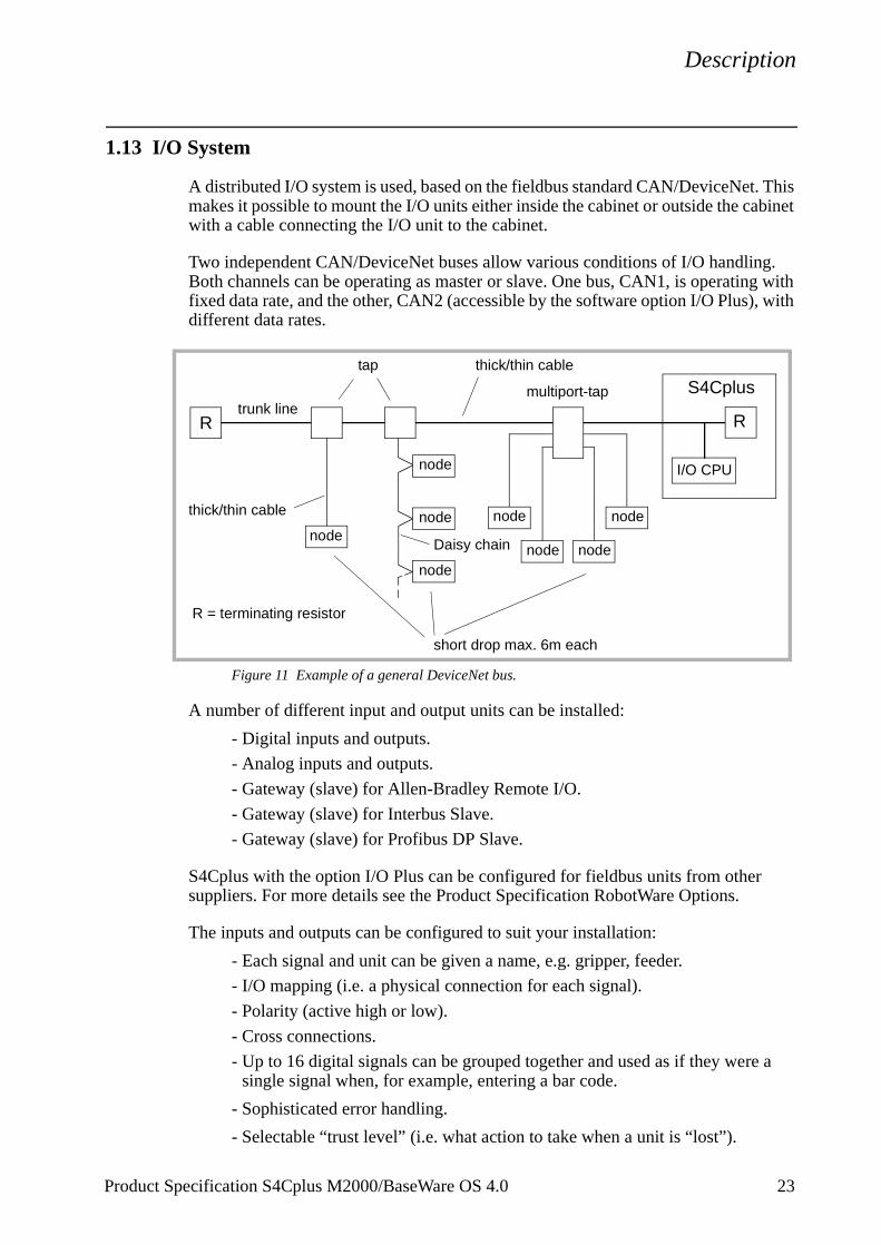
A distributed I/O system is used, based on the fieldbus standard CAN/DeviceNet. This makes it possible to mount the I/O units either inside the cabinet or outside the cabinet with a cable connecting the I/O unit to the cabinet.
Two independent CAN/DeviceNet buses allow various conditions of I/O handling. Both channels can be operating as master or slave. One bus, CAN1, is operating with fixed data rate, and the other, CAN2 (accessible by the software option I/O Plus), with different data rates.
Figure 11 Example of a general DeviceNet bus.
A number of different input and output units can be installed:
- Digital inputs and outputs.
- Analog inputs and outputs.
- Gateway (slave) for Allen-Bradley Remote I/O.
- Gateway (slave) for Interbus Slave.
- Gateway (slave) for Profibus DP Slave.
S4Cplus with the option I/O Plus can be configured for fieldbus units from other suppliers. For more details see the Product Specification RobotWare Options.
The inputs and outputs can be configured to suit your installation:
- Each signal and unit can be given a name, e.g. gripper, feeder.
- I/O mapping (i.e. a physical connection for each signal).
- Polarity (active high or low).
- Cross connections.
- Up to 16 digital signals can be grouped together and used as if they were a single signal when, for example, entering a bar code.
- Sophisticated error handling.
- Selectable “trust level” (i.e. what action to take when a unit is “lost”).
R R
node
node
node
node
node
node
node
node
I/O CPU
S4Cplustrunk line
tap thick/thin cable
multiport-tap
Daisy chain
thick/thin cable
short drop max. 6m each
R = terminating resistor
Product Specification S4Cplus M2000/BaseWare OS 4.0 23
Description
- Program controlled enabling/disabling of I/O units.
- Scaling of analog signals.
- Filtering.
- Polarity definition.
- Pulsing.
- TCP-proportional analog signal.
- Programmable delays.
- Simulated I/O (for forming cross connections or logical conditions without need the for physical hardware).
- Accurate coordination with motion.
Signals can be assigned to special system functions, such as program start, so as to be able to control the robot from an external panel or PLC.
The robot can function as a PLC by monitoring and controlling I/O signals:
- I/O instructions are executed concurrent to the robot motion.
- Inputs can be connected to trap routines. (When such an input is set, the trap routine starts executing. Following this, normal program execution resumes. In most cases, this will not have any visible effect on the robot motion, i.e. if a limited number of instructions are executed in the trap routine.)
- Background programs (for monitoring signals, for example) can be run in parallel with the actual robot program. Requires Multitasking option, see Product Specification RobotWare.
Manual functions are available to:
- List all the signal values.- Create your own list of your most important signals.- Manually change the status of an output signal.- Print signal information on a printer.
I/O signals can for some robots also be routed parallel or serial to connectors on the upper arm of the robot.
Types of connection
The following types of connection are available:
- “Screw terminals” on the I/O units- Industrial connectors on cabinet wall- Distributed I/O-connections inside or on cabinet wall
For more detailed information, see Chapter 2, Specification of Variants and Options.
ABB I/O units (node types)
Several I/O units can be used. The following table shows the maximum number of physical signals that can be used on each unit. Data rate is fixed at 500 Kbit/s.
24 Product Specification S4Cplus M2000/BaseWare OS 4.0
Description
Distributed I/O
The maximum number of logical signals is 1024 in total for the CAN/DeviceNet buses (inputs or outputs, group I/O, analog and digital including field buses)
CAN1 CAN2 (option)
Max. total no of units* 20 (including SIM units) 20Data rate (fixed) 500 Kbit/s 125/250/500 Kbit/s.Max. total cable length 100 m trunk + 39m drop up to 500mCable type (not included) According to DeviceNet specification release 1.2
* Max. four units can be mounted inside the cabinet.
Type of unit DSQC Optionno.
Digital Analog
Power supplyIn Out Voltageinputs
Voltage output
Current output
Digital I/O 24 VDC 328 20x 16 16 Internal/External1
1. The digital signals are supplied in groups, each group having 8 inputs or outputs.
Digital I/O 120 VAC 320 25x 16 16 Internal/External
Analog I/O 355 22x 4 3 1 Internal
AD Combi I/O 327 23x 16 16 2 Internal/External1
Relay I/O 332 26x 16 16 Internal/External1
Allen-Bradley Remote I/O Slave
350 241 1282
2. To calculate the number of logical signals, add 2 status signals for Allen-Bradley Remote I/O unit and 1 for Interbus and Profibus DP.
128
Interbus Slave 351 242-285 642 64
Profibus DP Slave 352 243-287 1282 128
Simulated I/O3
3. A non physical I/O unit can be used to form cross connections and logical conditions without physical wiring. No. of signals are to be configured. Some ProcessWares include SIM unit.
100 100 30 30
Encoder interface unit4
Encoder interfaceunit5
4. Dedicated for conveyor tracking only.5. Only for PickMaster 4.0
354
377
244
2491
Product Specification S4Cplus M2000/BaseWare OS 4.0 25
Description
26 Product Specification S4Cplus M2000/BaseWare OS 4.0
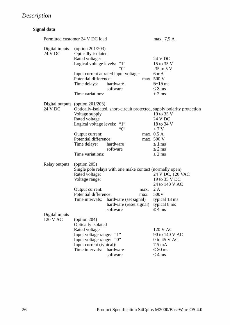
Signal data
Permitted customer 24 V DC load max. 7,5 A
Digital inputs (option 201/203)24 V DC Optically-isolated
Rated voltage: 24 V DCLogical voltage levels: “1” 15 to 35 V
“0” -35 to 5 VInput current at rated input voltage: 6 mAPotential difference: max. 500 VTime delays: hardware 5−15 ms
software ≤ 3 msTime variations: ± 2 ms
Digital outputs (option 201/203)24 V DC Optically-isolated, short-circuit protected, supply polarity protection
Voltage supply 19 to 35 VRated voltage 24 V DCLogical voltage levels: “1” 18 to 34 V
Relay outputs (option 205)Single pole relays with one make contact (normally open)Rated voltage: 24 V DC, 120 VACVoltage range: 19 to 35 V DC
24 to 140 V ACOutput current: max. 2 APotential difference: max. 500VTime intervals: hardware (set signal) typical 13 ms
hardware (reset signal) typical 8 mssoftware ≤ 4 ms
Digital inputs120 V AC (option 204)
Optically isolatedRated voltage 120 V ACInput voltage range: “1” 90 to 140 V ACInput voltage range: “0” 0 to 45 V ACInput current (typical): 7.5 mATime intervals: hardware ≤ 20 ms
software ≤ 4 ms
Description
Digital outputs 120 V AC (option 204)
Optically isolated, voltage spike protectionRated voltage 120 V ACOutput current: max. 1A/channel, 12 A
16 channelsor
max. 2A/channel, 10 A 16 channels(56 A in 20 ms)
min. 30mAVoltage range: 24 to 140 V ACPotential difference: max. 500 VOff state leakage current: max. 2mA rmsOn state voltage drop: max. 1.5 VTime intervals: hardware ≤ 12 ms
software ≤ 4 ms
Analog inputs (option 202)Voltage Input voltage: +10 V
Analog outputs (option 203)Output voltage (galvanically isolated): 0 to +10 V Load impedance: min. 2 kohmResolution: 2.44 mV (12 bits)Accuracy: ±25 mV ±0.5% of output
voltagePotential difference: max. 500 VTime intervals: hardware ≤ 2.0 ms
software ≤ 4 ms
System signals
Signals can be assigned to special system functions. Several signals can be given the same functionality.
Digital outputs Motors on/offExecutes program ErrorAutomatic modeEmergency stopRestart not possibleRun chain closed
Product Specification S4Cplus M2000/BaseWare OS 4.0 27
Description
Digital inputs Motors on/offStarts program from where it isMotors on and program startStarts program from the beginningStops programStops program when the program cycle is readyStops program after current instructionExecutes “trap routine” without affecting status of stoppedregular program1 Loads and starts program from the beginning1
Resets errorResets emergency stopSystem reset
Analog output TCP speed signal
1. Program can be decided when configuring the robot.
For more information on system signals, see User’s Guide - System Parameters.
28 Product Specification S4Cplus M2000/BaseWare OS 4.0
Description
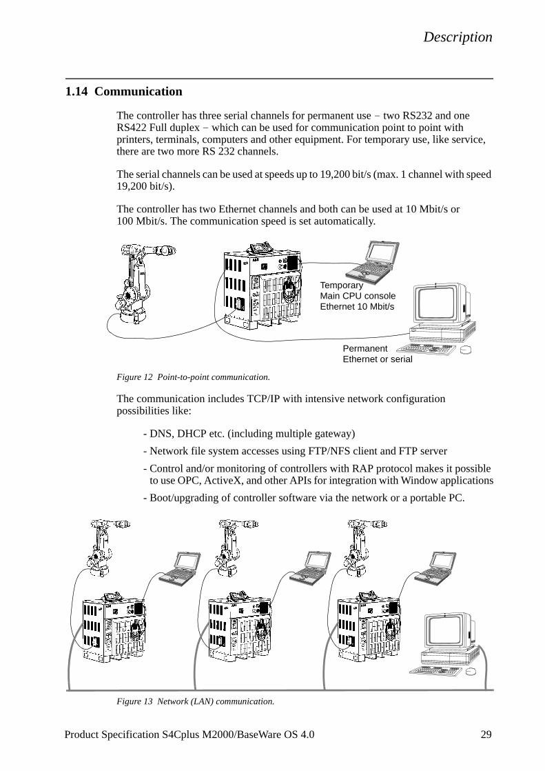
1.14 Communication
The controller has three serial channels for permanent use - two RS232 and one RS422 Full duplex - which can be used for communication point to point with printers, terminals, computers and other equipment. For temporary use, like service, there are two more RS 232 channels.
The serial channels can be used at speeds up to 19,200 bit/s (max. 1 channel with speed 19,200 bit/s).
The controller has two Ethernet channels and both can be used at 10 Mbit/s or 100 Mbit/s. The communication speed is set automatically.
Figure 12 Point-to-point communication.
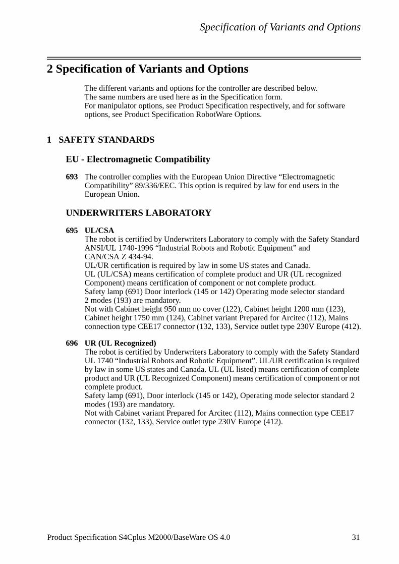
The communication includes TCP/IP with intensive network configuration possibilities like:
- DNS, DHCP etc. (including multiple gateway)
- Network file system accesses using FTP/NFS client and FTP server
- Control and/or monitoring of controllers with RAP protocol makes it possible to use OPC, ActiveX, and other APIs for integration with Window applications
- Boot/upgrading of controller software via the network or a portable PC.
Figure 13 Network (LAN) communication.
Temporary
Permanent
Main CPU consoleEthernet 10 Mbit/s
Ethernet or serial
Product Specification S4Cplus M2000/BaseWare OS 4.0 29
Description
30 Product Specification S4Cplus M2000/BaseWare OS 4.0
Specification of Variants and Options
2 Specification of Variants and Options
The different variants and options for the controller are described below.The same numbers are used here as in the Specification form. For manipulator options, see Product Specification respectively, and for software options, see Product Specification RobotWare Options.
1 SAFETY STANDARDS
EU - Electromagnetic Compatibility
693 The controller complies with the European Union Directive “Electromagnetic Compatibility” 89/336/EEC. This option is required by law for end users in the European Union.
UNDERWRITERS LABORATORY
695 UL/CSAThe robot is certified by Underwriters Laboratory to comply with the Safety Standard ANSI/UL 1740-1996 “Industrial Robots and Robotic Equipment” and CAN/CSA Z 434-94. UL/UR certification is required by law in some US states and Canada. UL (UL/CSA) means certification of complete product and UR (UL recognized Component) means certification of component or not complete product. Safety lamp (691) Door interlock (145 or 142) Operating mode selector standard2 modes (193) are mandatory.Not with Cabinet height 950 mm no cover (122), Cabinet height 1200 mm (123), Cabinet height 1750 mm (124), Cabinet variant Prepared for Arcitec (112), Mains connection type CEE17 connector (132, 133), Service outlet type 230V Europe (412).
696 UR (UL Recognized)The robot is certified by Underwriters Laboratory to comply with the Safety Standard UL 1740 “Industrial Robots and Robotic Equipment”. UL/UR certification is required by law in some US states and Canada. UL (UL listed) means certification of complete product and UR (UL Recognized Component) means certification of component or not complete product. Safety lamp (691), Door interlock (145 or 142), Operating mode selector standard 2 modes (193) are mandatory.Not with Cabinet variant Prepared for Arcitec (112), Mains connection type CEE17 connector (132, 133), Service outlet type 230V Europe (412).
Product Specification S4Cplus M2000/BaseWare OS 4.0 31
Specification of Variants and Options
32 Product Specification S4Cplus M2000/BaseWare OS 4.0
2 CONTROL SYSTEM
CABINET
Variant
111 Standard cabinet with upper cover.
112 Prepared for ArcitecRotary switch 80A (143) and Circuit breaker standard (147) and Arcitec 4.0 (556) are mandatory.Not with Wheels (126) or Mains connection type CEE17 connector (132, 133) or 6HSB (134) or Mains switch Flange disconnector (142) or Servo disconnector (144) or UL (695) or UR (696).
Cabinet Height (wheels not included in height)
121 Standard cabinet 950 mm with upper cover.122 Standard cabinet 950 mm without upper cover. To be used when cabinet extension is mounted
on top of the cabinet after delivery.Not with Door interlock (145) or UL (695) or UR (696).
123 Standard cabinet with 250 mm extension. The height of the cover increases the available space for external equipment that can be mounted inside the cabinet.Not with UL (695).
124 Standard cabinet with 800 mm extension. The extension is mounted on top of the standard cabinet. There is a mounting plate inside. (See Figure 14).The cabinet extension is opened via a front door and it has no floor. The upper part of the standard cabinet is therefore accessible.Not with UL (695) and Servo disconnector (144).
Figure 14 Mounting plate for mounting of equipment (dimensions in mm)
126 Cabinet on wheels. Increase the height by 30 mm.Not with Prepared for Arcitec (112).
730
705
20 665 9 (x4)
20
690
Specification of Variants and Options
Product Specification S4Cplus M2000/BaseWare OS 4.0 33
OPERATOR’S PANEL
The operator’s panel and teach pendant holder can be installed in different ways.
181 Standard, i.e. on the front of the cabinet.
182 External, i.e. in a separate operator’s unit. (See Figure 15 for required preparation)All necessary cabling, including flange, connectors, sealing strips, screws, etc., is supplied. External enclosure is not supplied.
183 External, mounted in a box. (See Figure 16)
Figure 15 Required preparation of external panel enclosure (all dimensions in mm).
184
224180
140
193196
70
62
45o
External panel enclosure(not supplied)
M8 (x4)
Connection to
Holes for flange
Holes for operator’s panel
Holes forteach pendant holder
the controller
90
1555 (x2)
Teach pendantconnection
200
240Required depth 200 mm
M4 (x4)
96
223
Specification of Variants and Options
Figure 16 Operator’s panel mounted in a box (all dimensions in mm).
OPERATING MODE SELECTOR193 Standard, 2 modes: manual and automatic.191 Standard, 3 modes: manual, manual full speed and automatic.
Does not comply with UL and UR safety standards.
CONTROLLER COOLING
472 Ambient temperature up to 45oC (113oF)Standard design. The computer unit is provided with a passive heat exchanger (cooling fins on the rear part of the box).
473 Ambient temperature up to 52oC (125oF)The computer unit is provided with an active Peltier cooling equipment (replaces the cooling fins from option 472.
337
370
M5 (x4) for fastening of box
Connection flange
34 Product Specification S4Cplus M2000/BaseWare OS 4.0
Specification of Variants and Options
Product Specification S4Cplus M2000/BaseWare OS 4.0 35
TEACH PENDANT601 Teach pendant with back lighting, connection cable 10 m.
606 10 mAn extension cable can be connected between the controller and the teach pendant.The total length of cable between the controller and the teach pendant should not exceed 30 m. Note that the length of the optional operator’s panel cable must be included in the limitation.
607 20 m
MAINS VOLTAGEThe control system can be connected to a rated voltage of between 200 V and 600 V, 3-phase and protective earthing. A voltage fluctuation of +10% to -15% is permissible.
For all robots except for IRB 6600/7600 the voltage range must be specified. This gives the possibility to select between three different transformers.
162 Voltage range 200, 220, 400, 440V163 Voltage range 400, 440, 475, 500V164 Voltage range 475, 500, 525, 600V
The robots IRB 7600 (all versions) and IRB 6650-125/3.2 are supplied with an external transformer, see Figure 17, except for the option 155. The mains voltage 475V does not need any drive system transformer.
Specification of Variants and Options
Figure 17 Transformer unit (dimensions in mm).
MAINS CONNECTION TYPE
The power is connected either inside the cabinet or to a connector on the cabinet’s left-hand side. The cable is not supplied. If option 133-136 is chosen, the female connector (cable part) is included.
131 Cable gland for inside connection. Diameter of cable: 11-12 mm.
132 CEE17-connector 32 A, 380-415 V, 3p + PE (see Figure 18).Not with Flange disconnector (142) or UL/UR (695/696) orService outlet power supply (432).Not available for IRB 6600/7600.
Figure 18 CEE male connector.
133 32 A, 380-415 V, 3p + N + PE (see Figure 18).Not with Flange disconnector (142) or UL/UR (695/696).Not available for IRB 6600/7600.
134 Connection via an industrial Harting 6HSB connector in accordance with DIN 41640. 35 A, 600 V, 6p + PE (see Figure 19).Cannot be combined with Flange disconnector (142).
Figure 19 DIN male connector.MAINS SWITCH141 Rotary switch 40 A in accordance with the standard in section 1.2 and IEC 337-1,
VDE 0113. Customer fuses for cable protection required.142 Flange disconnector in accordance with the standard in section 1.2.
Includes door interlock for flange disconnector and a 20A circuit breaker with interrupt capacity 14 kA.
0058 Flange disconnector in accordance with the standard in section 1.2.Includes door interlock for flange disconnector and a 20A circuit breaker with interrupt
560
398300
36 Product Specification S4Cplus M2000/BaseWare OS 4.0
Specification of Variants and Options
capacity 65 kA at 400V, 25 kA at 600V.143 Rotary switch 80 A. Customer fuses for cable protection required.
Included in the option Prepared for Arcitec (112).144 Servo disconnector.
This option adds a rotary switch 40 A to the two contactors in the AC power supply for the drive system. The handle can be locked by a padlock, e.g. in an off position.
145 Door interlock for rotary switch.Included in the options UL/CSA/UR (695, 696) and Servo disconnector (144).
147 Circuit breaker for rotary switch. A 16A (option 163 and 164) or 25A (option 162) circuit breaker for short circuit protection of mains cables in the cabinet. Circuit breaker approved in accordance with IEC 898, VDE 0660. Interrupt capacity 6 kA.
Product Specification S4Cplus M2000/BaseWare OS 4.0 37
Specification of Variants and Options
TIONSER
I/O INTERFACES
The standard cabinet can be equipped with up to four I/O units. For more details, see page 23.
Figure 20 I/O unit and screw terminal locations.
X4 MEASUREMENT SYSTEM 1
X5 MEASUREMENT SYSTEM 2
CAN 2
X14 EXPANSION BOARD
X2
AX
IS C
OM
PU
TE
R
SYST
EM
2X
20 D
RIV
E
8-PolPh.5-Pol
X3 DRIVE SYSTEM 1
X12 PANEL BOARD
15-Pol D-sub
25-Pol D-sub
15-Pol D-sub
ÄL
9-Pol D-sub
9-Pol D-sub
X15 CAN 1.1
X9 SIO2
CAN 1.2X6
X10 SIO1
Ph.5-Pol
X11 CONSOLE
9-Pol D-sub
RE
15-Pol D-sub
Ph.5-PolCAN 1.3X7
MSNS
X8
DSQC 504CAN 1
X1
I/O
CO
MP
UT
ER
25-P
ol D
-sub
DB
-44
X13 POWER SUPPLY
FCIMale
15-Pol
FCIFemale
15-Pol
CAN 2
Test
Ph.5-Pol
NS MS
GS2
X6,
CO
NT
RO
L P
AN
EL
X9,
BA
SE
CO
NN
UN
IT
X7,
TE
AC
H P
EN
DA
NT
11
1
DSQC 509
X2
X1
GS1ES2ES1NSMSEN
POWER UNIT / POWER CONTROL
RL2RL1
1
X5
1
X8
WARNING
ANY EXTERNAL EQUIPMENTREMOVE JUMPERS BEFORE CONNECTING
AS2AS1
CONNEC
X4
X3CUSTOMX1-X4
Cabinet view from above
X9 (COM3, RS422)
X7 (CAN 1.3) X8 (CAN 2)
X15 (CAN 1.1)
X6 (CAN 1.2)
Computer system
Base Connector Unit
XP8
XT21 XP6
XP5 XP58
I/O Units (X4)
X 1 - X 4Safety Signals
X10 (COM2, RS232)
XT 31(24V I/O)
(COM1, RS232)
Panel Unit
Manipulator connections115/230 VAC
Connection toCustomer powerCustomer signals
Connection toPosition switches
38 Product Specification S4Cplus M2000/BaseWare OS 4.0
Specification of Variants and Options
201 Digital 24 VDC I/O: 16 inputs/16 outputs.
202 Analog I/O: 4 inputs/4 outputs.
203 AD Combi I/O: 16 digital inputs/16 digital outputs and 2 analog outputs (0-10V).
204 Digital 120 VAC I/O 16 inputs/16 outputs.
205 Digital I/O with relay outputs: 16 inputs/16 outputs. Relay outputs to be used when more current or voltage is required from the digital outputs. The inputs are not separated by relays.
Connection of I/O
251 Internal connection (options 201-204, 221-224, 231-234, 251-254, 261-264)The signals are connected directly to screw terminals on the I/O units in the upper part of the cabinet (see Figure 20).
252 External connectionThe signals are connected via 64-pole standard industrial connector in accordance with DIN 43652. The connector is located on the left-hand side of the controller. Corresponding customer part is included.
208 Prepared for 4 I/O unitsThe internal CAN/Devicenet cabling to the I/O units exists in two versions, one for up to two I/O units and one for up to four I/O units. The versions are selected to match the number of ordered I/O units. By this option it is possible to get the four unit version even if less than three I/O units are ordered.
SAFETY SIGNALS
206 Internal connectionThe signals are connected directly to screw terminals in the upper part of the cabinet (see Figure 20).
207 External connectionThe signals are connected via 64-pole standard industrial connector in accordance with DIN 43652. The connector is located on the left-hand side of the controller. Corresponding customer part is included.
FIELD BUS AND COMMUNICATION
245 CAN/DeviceNetConnection on the left side to two 5-pole female connectors in accordance with ANSI.(Male connectors are supplied).
240 LAN/EthernetRJ45 connector to be used for LAN connector.(When the connector is not used, a protective hood covers it).
246 Profibus DP Master/SlaveThe hardware of the Profibus-DP field bus consists of a master/slave unit, DSQC 510, and distributed I/O units, called slave units. The DSQC 510 unit is mounted in the S4Cplus computer system where it is connected to the PCI bus while the slave units are attached to the field bus network.
Product Specification S4Cplus M2000/BaseWare OS 4.0 39
Specification of Variants and Options
The slave units can be I/O units with digital and/or analogue signals. They are all controlled via the master part of the DSQC 510 unit.
The slave part of the DSQC 510 is normally controlled by an external master on aseparate Profibus-DP network. This network is a different one than the network holding the slave units for the master part of the board. The slave part is a digital input and output I/O unit with up to 512 digital input and 512 digital output signals.
The signals are connected to the board front (two 9-pole D-sub). 19 units (internal or external) can be connected to the cabinet.
Profibus DP M/S CFG Tool (option 270) is required when setting up the master part or when changing the number of signals for the slave part. For more information see Product Specification RobotWare Options.
247/248 Interbus Master/SlaveThe hardware of the Interbus field bus consists of a Master/Slave unit (DSQC512/529)and distributed I/O units. The master and the slave units are two separate boards connected by a flat cable. The DSQC512/529 unit is connected to the S4Cplus robot controller PCI bus while the I/O units are attached to the field bus net.
The I/O units may be digital or analog modules. They are all controlled by the master part of the DSQC512/529 unit.
The slave part of the DSQC512/529 unit is normally controlled by an external master on a separate Interbus network. This network is a different one than the network holding the I/O units for the master part of the board. The slave part is a digital in- and output I/O unit with up to 160 digital in- and 160 digital out signals.
Two variants are available:247 for optical fibre connection (DSQC512)248 for copper wire connection (DSQC529)
Interbus M/S CFG Tool (option 271) is required when setting up the master part or when changing the number of signals for the slave part. For more information see Product Specification RobotWare Options.
GATEWAY UNITS
For more details, see I/O System on page 23.
241 Allen-Bradley Remote I/OUp to 128 digital inputs and outputs, in groups of 32, can be transferred serially to a PLC equipped with an Allen Bradley 1771 RIO node adapter. The unit reduces the number of I/O units that can be mounted in cabinet by one. The field bus cables are connected directly to the A-B Remote I/O unit in the upper part of the cabinet (see Figure 20). Connectors Phoenix MSTB 2.5/xx-ST-5.08 or equivalent are included.
242 Interbus SlaveUp to 64 digital inputs and 64 digital outputs can be transferred serially to a PLC equipped with an InterBus interface. The unit reduces the number of I/O units that can be mounted in the cabinet by one. The signals are connected directly to the InterBus slave unit (two 9-pole D-sub) in the upper part of the cabinet.
40 Product Specification S4Cplus M2000/BaseWare OS 4.0
Specification of Variants and Options
243 Profibus DP SlaveUp to 128 digital inputs and 128 digital outputs can be transferred serially to a PLC equipped with a Profibus DP interface. The unit reduces the number of I/O units that can be mounted in the cabinet by one. The signals are connected directly to the Profibus DP slave unit (one 9-pole D-sub) in the upper part of the cabinet.
244 Encoder interface unit for conveyor tracking (DSQC 354)Conveyor Tracking, RobotWare option 540, is the function whereby the robot follows a work object which is mounted on a moving conveyor. The encoder and synchronization switch cables are connected directly to the encoder unit in the upper part of the cabinet (see Figure 20). Screw connector is included. This option is also required for the function Sensor Synch, RobotWare option 547.
249 Encoder interface unit for conveyor tracking (DSQC 377)Only available for IRB 140 and IRB 340, required for PickMaster 4.0. Physically similar to option 344.
EXTERNAL I/O UNITS
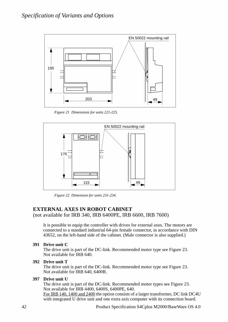
I/O units can be delivered separately. The units can then be mounted outside the cabinet or in the cabinet extension. These are connected in a chain to a connector (CAN 3 or CAN 2, see Figure 20) in the upper part of the cabinet. Connectors to the I/O units and a connector to the cabinet (Phoenix MSTB 2.5/xx-ST-5.08), but no cabling, is included. Dimensions according to Figure 21 and Figure 22. For more details, see I/O System on page 23.
221 Digital I/O 24 V DC: 16 inputs/16 outputs.
222 Analog I/O.
223 AD Combi I/O: 16 digital inputs/16 digital outputs and 2 analog outputs (0-10V).
224 Digital I/O 120 V AC: 16 inputs/16 outputs.
225 Digital I/O with relay outputs: 16 inputs/16 outputs.
EXTERNAL GATEWAY UNITS231 Allen Bradley Remote I/O
232 Interbus Slave
233 Profibus DP Slave
234 Encoder interface unit DSQC 354 for conveyor tracking
235 Encoder interface unit DSQC 377 for conveyor tracking (IRB 140 and IRB 340 only)
Product Specification S4Cplus M2000/BaseWare OS 4.0 41
Specification of Variants and Options
Figure 21 Dimensions for units 221-225.
Figure 22 Dimension for units 231-234.
EXTERNAL AXES IN ROBOT CABINET (not available for IRB 340, IRB 6400PE, IRB 6600, IRB 7600)
It is possible to equip the controller with drives for external axes. The motors are connected to a standard industrial 64-pin female connector, in accordance with DIN 43652, on the left-hand side of the cabinet. (Male connector is also supplied.)
391 Drive unit C The drive unit is part of the DC-link. Recommended motor type see Figure 23.Not available for IRB 640.
392 Drive unit TThe drive unit is part of the DC-link. Recommended motor type see Figure 23.Not available for IRB 640, 6400R.
397 Drive unit UThe drive unit is part of the DC-link. Recommended motor types see Figure 23.Not available for IRB 4400, 6400S, 6400PE, 640.For IRB 140, 1400 and 2400 the option consists of a larger transformer, DC link DC4U with integrated U drive unit and one extra axis computer with its connection board.
195
203 49
EN 50022 mounting rail
49115
170
EN 50022 mounting rail
42 Product Specification S4Cplus M2000/BaseWare OS 4.0
Specification of Variants and Options
Product Specification S4Cplus M2000/BaseWare OS 4.0 43
No cabling from the drive unit U to cabinet wall is included.For IRB 6400R the option consists of a DC link DC4U with integrated U drive unit with cabling to the cabinet wall.
393 Drive unit GTA separate drive unit including two drives. Recommended motor type see Figure 23.Not available for IRB 4400, 6400R, 6400S
396 Prepared for drives GTThe same as 393 but without the GT drive module. The preparation includes; larger transformer, larger DC link DC2, and one additional axis computer with its connection board.Not available for IRB 4400, 640, 6400R, 6400S
398 Prepared for drives GTThe same as 396 but without additional axes computer and connection board.
399 Prepared for drives GUThe same as 396 but intended for a GU drive module. The preparation includes: larger transformer, larger DC link DC4, and one additional axis computer with its connection board.Not available for IRB 4400, 640, 6400R, 6400S.
394 Drive unit T+GTA combination of 392 and 393.Not available for IRB 4400, 640, 6400R, 6400S
395 Drive unit C+GTA combination of 391 and 393Not available for IRB 4400, 640, 6400R, 6400S
365 TrackmotionA special wiring for the three motor combination 394 (IRB 140, 1400, 2400 only) to be used when axis 7 is intended for an ABB Trackmotion. The drive unit in the DC link and the Trackmotion measurement board is then connected to the robot axes computer 1 while the drive unit and the measurement board for motor 8 and 9 is connected to axes computer 2. All motor power wiring is routed to one common connector, XS7.
701-706 Servo gun interfacing (IRB 6400R, IRB 6600 and 7600)
For further information see the Product Specification IRB 6400R chapter Servo Gunor IRB 6600 chapter Servo Gun (overview), and the Product Specification RobotWare Options (function description).
701 Stationary gun (SG)
IRB 6400RThe option consists of an encapsulated Serial Measurement Board (SMB) and cabling inside the controller.The cabling between SMB and the controller is selected in the option range 686-689.Drive unit 397 is required.
IRB 6600/7600The option includes cabling inside the controller and the manipulator, and a 7m resolver cable between the manipulator and the welding gun pedestal. The customer connector to this cable should be an 8-pin Burndy, wired according to Motor Unit
Specification of Variants and Options
specification.The cable between the controller DDU and the welding gun pedestal is selected in the option range 686-687 (different lengths). The customer connector to this cable should be of Industrial Multi-connector type, corresponding to the manipulator CP/CS (see Product Specification IRB 6600/7600). Besides the necessary motor wiring, it also contains 12 wires for gun I/O, accessible on screw terminals in the cabinet.Drive unit 381 (DDU-V) must be selected.
702 Robot Gun (RG)
IRB 6400RThe option consists of an encapsulated SMB and cabling inside the controller.It also includes bracket for 6400R foot mounting of the SMB box, and cabling between the SMB box and the manipulator.The cabling between SMB and the controller is selected in th option range 681-684. Drive unit option 397 is required.
IRB 6600/7600The option includes cabling inside the controller and the manipulator. The cable between the controller and the manipulator is selected in the option range 697-699. Besides the necessary motor wiring the cable also contains 22 wires for gun I/O and CAN/DeviceNet fieldbus. The I/O wiring is accessible on screw terminals in the cabinet.Drive unit 381 (DDU-V) must be selected.
703 One SG and one RG
IRB 6400RThe option is a combination of 701 and 702. A distributed drive unit (DDU) controls the SG motor. The cabling between the SG SMB and the controller is selected in the option range 686-689, and the cabling between the RG SMB and the controller is selected in the option range 681-684.Drive unit options 397 (for the RG) and 380 (for the SG) are required.
IRB 6600/7600The option includes cabling inside the controller and the manipulator. The cable between the controller and the welding gun pedestal is selected in the option range 686-687. The customer connector to this cable should be of Industrial Multi-connector type, corresponding to the manipulator CP/CS (see Product Specification IRB 6600/7600). Besides the necessary motor wiring it also contains 12 wires for gun I/O, accessible on screw terminals in the cabinet.
The cable between the controller and the manipulator is selected in the option range 697-699. Besides the necessary motor wiring the cable also contains 22 wires for gun I/O and CAN/DeviceNet fieldbus.
The option also consists of an SMB box for two resolvers, a serial cable between the box and the controller (the same length as 641-642), and two resolver cables, one 1.5m for the RG and one 7m for the SG. The customer connector to the SG cable should be an 8-pin Burndy, wired according to the Motor Unit specification. The SMB box should be mounted close to the manipulator foot. Dimensions and mounting information can be found in the Product Specification Motor Unit.Drive unit 382 (DDU-VW) must be selected.
44 Product Specification S4Cplus M2000/BaseWare OS 4.0
Specification of Variants and Options
704 Twin SG
IRB 6400RThe option is a combination of two options 701. A distributed drive unit controls the second SG motor.The cabling between the SG SMBs and the controller is selected in the option range 686-689.Drive unit options 397 (for one SG) and 380 (for the second SG) are required.
IRB 6600/7600The option includes cabling inside the controller. The two cables between the controller and the pedestals are selected in the option range 686-687.Customer connectors to the cables should be of Industrial Multi-connector type, corresponding to the manipulator CP/CS (see Product Specification IRB 6600/7600). Besides the necessary motor wiring, the cables also contain 12 wires for gun I/O, accessible on screw terminals in the cabinet (SG axis 7), or on the Multi connector inside (SG axis 8) the DDU.
The option also consists of an SMB box for two resolvers, a serial cable between the box and the controller (the same length as 686-687), and two 7m resolver cables. The customer connector to the SG cable should be an 8-pin Burndy, wired according to the Motor Unit specification.The SMB box should be mounted close to the manipulator foot.Dimensions and mounting information can be found in the product Specification Motor Unit.
Drive unit 382 (DDU-VW) must be selected.
705 SG and Track Motion (T)
IRB 6400RThe option is a combination of 701 and a track motion IRBT 6002S controlled by a distributed drive unit.The cabling between the SG SMB and the controller is selected in the option range 686-689.Drive unit options 397 (for the SG) and 380 (for the T) are required.
IRB 6600/7600The option includes cabling inside the controller. The cable between the controller and the welding gun pedestal is selected in the option range 686-687.The customer connector to the cable should be of Industrial Multi-connector type, corresponding to the manipulator CP/CS (see Product Specification IRB 6600/7600).Besides the necessary motor wiring the cable also contains 12 wires for gun I/O, accessible on screw terminals in the cabinet.The resolver cable for the SG must be ordered together with the Track Motion. The customer connector to the cable should be an 8-pin Burndy, wired according to the Motor Unit specification.
The SMB box and the power cable between the controller and the Track Motion are included in the Track Motion delivery. The serial measurement cable between the controller and the Track Motion are included in option 705 (length according to 641-642).
Drive unit 382 (DDU-VW) must be selected.
Product Specification S4Cplus M2000/BaseWare OS 4.0 45
Specification of Variants and Options
706 RG and T
IRB 6400RThe option is a combination of 702 and a track motion IRBT 6002S controlled by a distributed drive unit.The cabling between the RG SMB and the controller is selected in the option range 681-684.Drive unit options 397 (for the SG) and 380 (for the T) are required.
IRB 6600/7600The option includes cabling inside the controller. The RG cable between the controller and Track Motion is selected in the option range 697-699 except for the track motor cable which is included in the Track Motion delivery.Besides the necessary motor wiring, the RG cable also contains 22 wires for gun I/O and CAN/DeviceNet fieldbus.The option also consists of a 1.5m resolver cable for the RG to be connected to the Track Motion mounted SMB box.
Drive unit 382 (DDU-VW) must be selected.
EXTERNAL AXES MEASUREMENT BOARD (not available for IRB 340, IRB 6400PE)
The resolvers can be connected to a serial measurement board outside the controller.
387 Serial measurement board as separate unit
EXTERNAL AXES - SEPARATE CABINET(not available for IRB 340, IRB 6400PE)
An external cabinet can be supplied when there is not space enough in the standard cabinet. The external cabinet is connected to one Harting connector (cable length 7 m) on the left-hand side of the robot controller.Door interlock, mains connection, mains voltage and mains filter according to the robot controller. One transformer and one mains switch are included.
371/372 Drive unit GT, for 4 or 6 motors. Recommended motor types see Figure 23.373 Drive unit ECB, for 3 or 6 motors. Recommended motor types see Figure 23.374 Drive unit GT + ECB375 Drive unit GT + GT + ECB
46 Product Specification S4Cplus M2000/BaseWare OS 4.0
Specification of Variants and Options
Product Specification S4Cplus M2000/BaseWare OS 4.0 47
Figure 23 Motor selection table. Motor types according to external axes Motor Unit.
380 Drive unit DDU-UA separate box (H=500mm W=300mm D=250mm)including a DC link DC4 and a drive unit GU wherethe U part is used (the G part is not connected).The DDU-U is operated from an additional axis computor, included in the option.DDU-U is mainly intended for Servo Gun solutionsaccording to options 703-706 and is available for IRB 4400 and 6400R.
381 Drive unit DDU-V (IRB 6600/7600)382 Drive unit DDU-VW (IRB 6600/7600)383 Drive unit DDU-W (IRB 6600/7600)
A separate box (H=500mm, W=300mm, D=250mm) including a DC link DC5 and a drive unit VW.The box has 4 keyholes on the back of the encapsulation for fastening. Connection cabling (length 5m) to the controller is included.
The DDU-VW is operated from an additional axis computer included in the option, while the DDU-V and -W are operated from the basic robot axes computer.The options also include appropriate cabling inside themanipulator for different resolver configurations, seeProduct Specification IRB 6600, chapter Servo Gun.E.g. 7 axes applications utilise the built in 7 resolver SMB.
The DDU-V and VW are mainly intended for Servo Gun solutions according to options 701-706.The DDU-W is intended for a Track Motion withoutServo Gun.
Drive unit identity
Motor max current Arms
Drive unit rated current Arms
Suitable motor type
W 11.5-57 30 XL
V 5.5-26 14.5 XL
U 11 - 55A 24A M, L
G 6 - 30A 16A S, M, L
T 7.5-37 20 S, M, L, XL
E 4 - 19A 8,4A S, M
C 2,5 - 11A 5A S
B 1,5 - 7A 4A S
Specification of Variants and Options
EQUIPMENTManipulator cable, external connectors
653 Standard
Cable length
641 7m642 15 m, not available for IRB 140643 22 m, not available for IRB 140644 30 m, not available for IRB 140649 3 m, only available for IRB 140
Manipulator connection (only available for IRB 340)
657 External (not for the SA-version i.e. WashDown)658 Internal
Protection for manipulator cable
845 Each unit length is 2 m. Totally 40 m protection can be specified.
SERVICE OUTLET
Any of the following standard outlets with protective earthing can be chosen for maintenance purposes.The maximum load permitted is 500 VA (max. 100 W can be installed inside the cabinet).
411 120 V in accordance with American standard; single socket, Harvey Hubble.
412 230 V mains outlet in accordance with DIN VDE 0620; single socket suitable for EU countries.
POWER SUPPLY (to the service outlet)
431 Connection from the main transformer.The voltage is switched on/off by the mains switch on the front of the cabinet.
432 Connection before mains switch without transformer.Note this only applies when the mains voltage is 400 V, three-phase with neutralconnection and a 230 V service socket.Note! Connection before mains switch is not in compliance with some nationalstandards, NFPL 79 for example.
MEMORY
Removable mass memory
320 Floppy driveThe disk drive normally works well at temperatures up to 40oC (104oF). The disk drive
48 Product Specification S4Cplus M2000/BaseWare OS 4.0
Specification of Variants and Options
will not deteriorate at higher temperatures but there will be an increase in the number of reading/writing problems as the temperature increases.
Extended mass memory
310 Flash disc 128 Mb. Standard is 64 Mb
Product Specification S4Cplus M2000/BaseWare OS 4.0 49
Specification of Variants and Options
50 Product Specification S4Cplus M2000/BaseWare OS 4.0