STDE-B-XH0414H02RII06E-0010-1 P.1/12 Product Specifications Type : Reflowable XH Capacitor Model : XH414H II06E Seller: SII Micro Parts Ltd. Address: Arcacentral 13F, 2-1 Kinshi 1-Chome Sumida-ku Tokyo, Japan Postal code: 130-0013 Sales Dep. This is a "Standard Spec sheet " which is a general documentation for your evaluation. Before we will start to supply this part to you, we would like you to ask us the formal version of this spec sheet. We will issue the formal specification sheet for you. (Basically the contents is the same as this one.) We would like you to put your signature on it to state your approval of the specification, and send it back to us. It will be a kind of contract between you and us.
Transcript
STDE-B-XH0414H02RII06E-0010-1
P.1/12
Product Specifications Type : Reflowable XH Capacitor
Model : XH414H II06E
Approval of Customer Date :
Company Name :
Responsible person :
Signature :
Seller: SII Micro Parts Ltd.
Address: Arcacentral 13F, 2-1 Kinshi 1-Chome Sumida-ku Tokyo, Japan Postal code: 130-0013
Responsible person: Sales Dep. General Manager Shigeo Niwa
Signature: (Not applicable to submit this specification by e-mail)
This is a "Standard Spec sheet " which is a general
documentation for your evaluation. Before we will start to supply this part to you,
we would like you to ask us the formal version of this spec sheet.
We will issue the formal specification sheet for you. (Basically the contents is the same as this one.)
We would like you to put your signature on it to state your approval of the specification, and send it back to us.
It will be a kind of contract between you and us.
STDE-B-XH0414H02RII06E-0010-1
P.2/12
History of Revision No. Described Details of Change Checked Issue Date
01 Engineering Dept.
K. Tomitsuka
Initial Release for Standard Specifications QA Sec.
Y. Saito
Jul. 16, 2004
02 QA Sec.
Y. Saito Reworded 7-2 Engineering Dept.
K. Tomitsuka Nov.5,2004
03 QA Sec.
Y. Saito Had added model name in Reflow profile
Ver. STDE-B-XH0414H02RII06E-0008-3
Engineering Dept.
K. Tomitsuka Dec.24,2004
04 QA Sec.
Y. Saito Changed seller’s address
Ver. STDE-B-XH0414H02RII06E-0010-1
QA Sec.
H. Ishikawa Oct. 14,2005
Manufacturer information
Company name: SII Micro Parts Ltd. Address: 45-1, Aza-Matsubara, Kami-ayashi, Aoba-ku, Sendai-shi, Miyagi,
Japan, postal code: 989-3124
Responsible person:
Quality Assurance Section Manager
Isamu Shinoda
Signature:
(Not applicable to submit this specification by e-mail)
Contents page Cover page for the customer approval 1 History of revision
Manufacturer Information 2
Index 3 1 Application 4 2 Model 4 3 Chemical System and Structure 4 4 Nominal Specifications 4 5 Characteristics 5 6 Measuring Methods 6 7 Test Methods 9 8 Mounting Methods 10 9 Indications (Markings) 10
10 Inspection (Outgoing and Incoming) 11 11 Package Specifications 11 12 In case of quality trouble 11 13 Operation of this Specification 11 14 Notice 12
Appendix
Leakage Criteria Construction of Capacitor Capacitor drawing with tabs Explanation of coplanarity Reflow Profile Drawing of Emboss Carrier Tape Capacitor position in emboss tape Taping specifications Package specifications Precautions for Your Safety
STDE-B-XH0414H02RII06E-0010-1
P.4/12
1. Application This specification applies to the coin-type Reflowable XH Capacitor, which SII Micro Parts Ltd. manufactures and supplies to the customer specified in the cover page of this document.
2. Model Refer to the Model in this cover page.
3. Chemical System and Structure Refer to the document attached as “The construction of capacitor”.
4. Nominal Specifications Model
No. Characteristics XH414H
4-1 Operating temperature range -25°C to +70°C
4-2 Rated Operating Voltage 3.3V
4-3 Charging voltage 3.3V or less
4-4 Nominal Capacity Discharge capacity 0.015 mAh (3.3V to 2.0V) Electrostatic capacity 0.07F (3.3V to 0.0V)
4-8 Recommended Storage conditions Temperature +10°C to +30°C Humidity 60%RH or less
4-9 The voltage at the delivery time (V)
0.3 Max.
STDE-B-XH0414H02RII06E-0010-1
P.5/12
5. Characteristics Model Test Measuring
No. Characteristics XH414H Methods
Methods
1 Capacity (initial) 7-1 6-2-1 24°C 0.01 mAh or more -25°C 50% or more of value measured at 24°C 70°C 80% or more of value measured at 24°C 2 Internal impedance (initial) 7-1 6-3 24°C 150ohm or less -25°C 1000 ohm or less 70°C 1000 ohm or less 3 Over Charge (Floating) Characteristics 7-2 Capacity 70% or more of initial value measured at 24°C 6-2-1 Internal
impedance 1000 ohm or less 6-3
4 High Temperature and High Humidity Storage Characteristics 7-3 Capacity 70% or more of initial value measured at 24°C 6-2-1 Internal
impedance 1000 ohm or less 6-3
5 Charge / Discharge Cycle Characteristics 7-4 Capacity 70% or more of initial value measured at 24°C 6-2-1 Internal
impedance 1000 ohm or less 6-3
6 Leakage Resistance
Level S3 (*1) or less (There is no significant leakage, which effects capacitor’s performance.)
7-5 6-5
7 Appearance 6-5 Initial No leakage.
There is no foreign body adhesion (over level S2). There is no significant deformation, stain, stricken mark, rust and burr.
Initial
After Test There is no significant leakage (C1 or more), deformation, stain, stricken mark, rust and burr.
7-2 7-3 7-4
*1: Refer to “Leakage Criteria” “Initial” means within one month after deliver.
STDE-B-XH0414H02RII06E-0010-1
P.6/12
6. Measuring Methods 6-1. Measuring Environment, Meters and Equipment
6-1-1: Environment Testing and Measuring must be conducted under the environment of the normal temperature (24+/-2°C) and the normal humidity (65+/-20%RH), if not specified.
6-1-2: Dimensions For measuring dimension JIS B 7503 (Dial gauge), JIS B 7507 (Vernier caliper) and JIS B 7502 (External micrometer) or meter with same grade in accuracy must be used.
6-1-3: DC Voltmeter Voltmeter with class 0.2 of JIS C 1102 (Electric indicating instrument) or meter with same or better grade in accuracy, and its input impedance is over 10Mohm must be used.
6-1-4: DC Ammeter and AC Ammeter Ammeter with class 0.2 of JIS C 1102 (Electric indicating instrument) or meter with same or better grade in accuracy must be used.
6-1-5: Resistance Resistance should include all resistance in external circuit and its tolerance must be within +/-0.5%.
6-1-6: Initialization of capacitor All measurements must be conducted after 30 minutes of short-circuit.
6-2. Capacity 6-2-1. Discharge capacity
1) Charging condition: Charge capacitor by voltage of 3.3V through protective resistance of 100 ohms for 5 hours.
2) Discharging condition: Discharge the capacitor by using constant current of 20uA to 2.0V. Then the capacity is calculated by the duration. The electrical discharge by the fixed resistance of 100kohm is allowed as substitution of 20uA in a fixed current ampere. However, the calculation of capacity must be used the division mensuration.
( ) ( )∑
−××
+=
++
iii
ii TTVVRd
CCapacity 11 1
2)(
STDE-B-XH0414H02RII06E-0010-1
P.7/12
6-2-2. Electrostatic Capacity (for reference) 1) Follow next measuring method in the circuit shown in Fig. 6-2-1. 2) Set DC voltage (E) as listed in Table 6-2. 3) Turn SW toward 1 for charging. Charge and impress listed voltage (E) for listed
time (T) in Table 6-2 through protective resistance (R). 4) After having impressed the voltage for listed time, then turn SW toward 2 for
discharging by listed discharging current (I) in Table 6-2 through constant-current load device.
5) Measure the time while the tab-voltage of product (capacitor) changes from listed starting voltage (V1) to ending voltage (V2) in Table 6-2 (Td=T2-T1). Then calculate capacity (C) by following formula. Please refer to Fig. 6-2-2.
<Fig. 6-2-1 : Measureing Circuit>
E V
C : Test SampleE : DC Constant-voltage PowerR : Protective ResistanceV : DC VoltmeterI : Constant-current Load DeviceA : DC Ammeter
A
C
R
I
1 2SW
V 1
V 2
T
T 2
T1
E
Td
<Fig. 6-2-2 : Charging and discharging Curve>
<Table: 6-2>
Model Charging voltage
(E)
Protective Resistance
(R)
Charging Time (T)
Discharging Current
(I)
Starting Voltage
(V1)
Ending Voltage
(V2) XH414H 3.30V 100ohm 30 min. 20uA 2.0V 1.5V
C (F) = I x (T2 - T1)
V1 - V2
STDE-B-XH0414H02RII06E-0010-1
P.8/12
6-3. Internal Impedance Measure by alternating method with Frequency 1kHz.
6-4. Charging Current (for reference) After test sample is charged in the circuit shown in Fig.6-4 by listed voltage (E) and listed protective resistance (R) for listed time in Table 6-4, measure the voltage (V) between tabs of protective resistance (R). Then calculate charging current (I) by following formula.
C
ER
<Fig. 6-4 Charging CurrentMeasuring Circuit>
V
<Table 6-4>
Charging voltage
(E)
Protective resistance
(R)
Charging Time (T)
3.30V 100ohm 30 min.
6-5. Appearance: Refer to “Leakage Criteria” After Test : Use microscope, which has magnification of from 10 to 15. General : Naked eye
I = V
R
STDE-B-XH0414H02RII06E-0010-1
P.9/12
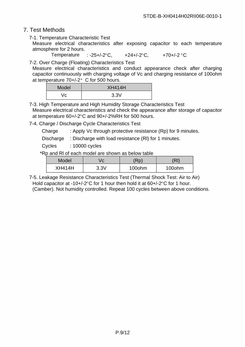
7. Test Methods 7-1. Temperature Characteristic Test
Measure electrical characteristics after exposing capacitor to each temperature atmosphere for 2 hours.
Temperature : -25+/-2°C, +24+/-2°C, +70+/-2 °C 7-2. Over Charge (Floating) Characteristics Test
Measure electrical characteristics and conduct appearance check after charging capacitor continuously with charging voltage of Vc and charging resistance of 100ohm at temperature 70+/-2°C for 500 hours.
Model XH414H Vc 3.3V
7-3. High Temperature and High Humidity Storage Characteristics Test Measure electrical characteristics and check the appearance after storage of capacitor at temperature 60+/-2°C and 90+/-2%RH for 500 hours.
7-4. Charge / Discharge Cycle Characteristics Test Charge : Apply Vc through protective resistance (Rp) for 9 minutes. Discharge : Discharge with load resistance (Rl) for 1 minutes. Cycles : 10000 cycles
*Rp and Rl of each model are shown as below table Model Vc (Rp) (Rl)
XH414H 3.3V 100ohm 100ohm
7-5. Leakage Resistance Characteristics Test (Thermal Shock Test: Air to Air) Hold capacitor at -10+/-2°C for 1 hour then hold it at 60+/-2°C for 1 hour. (Camber). Not humidity controlled. Repeat 100 cycles between above conditions.
STDE-B-XH0414H02RII06E-0010-1
P.10/12
8. Mounting Methods 8-1. Capacitor with tabs
1) For soldering iron Use the conditions as follows
Model XH414H
Temperature 260°C or less Soldering time Within five seconds
Within above conditions, do not heat capacitor over 100°C. Do not solder directly to the capacitor.
2) Dip soldering It is possible to apply. Do not heat the capacitor over 100°C.
3) Reflow soldering It is possible to apply. Execute it when the capacitor has the voltage of 0.3V or less. Refer to “Reflow Profile” attached.
8-2. Capacitor without tabs Use the spring terminal, which meets the specification as follows.
Surface treatment: Nickel plating or Gold plating Contact force: 0.5N or more
Note contact failure with the terminal because the ink of the insulation thing adheres on the side of capacitor.
9. Indications (Markings) 9-1. Dies
Following items are indicated on the surface of capacitor. (1) Model code (2) Positive polarity (+) (3) Name of Manufacturer, or monogram (4) Country of origin
Above items can be omitted except item (2). 9-2. Lot number
As lot number, the date when the product was manufactured is marked on the main body of the product and on the label of each minimum package. The following system applies to marking of the lot number. The lot number is composed from 2 to 4 characters, and two characters of the head means the lot number. The head means an end of the Christian era, and the next means an abbreviation of month. Two characters of the back are used by the manufacturer, and might be omitted.
Example: 11…manufactured in January 2001 2Y...manufactured in November 2002 Abbreviation of month: Jan. (1), Feb. (2),.., Sep. (9) Oct. (0), Nov. (Y), Dec. (Z)
The position is random. 2Y**
STDE-B-XH0414H02RII06E-0010-1
P.11/12
10. Inspection (Outgoing and Incoming) 10-1. Lot composition
Lot must be composed within the same manufacturing conditions. 10-2. Outgoing Inspection
SII Micro Parts Ltd., shall do outgoing inspection before shipping. The inspection items are as below table. The inspection results shall be submitted immediately for the customer request.
No Characteristics Inspection levels Frequency 1 Capacity (initial) n=6, c=0 per lot 2 Internal Impedance (initial) n=6, c=0 per lot 3 Leakage Resistance n=10, c=0 per lot
10-3. Incoming Inspection The customer should do incoming inspection within 30 days from the receiving day. If defects are find out at the incoming inspection, the customer immediately should notify to SII Micro Parts Ltd. in writing, with the defective products, for replacement request. When there was no connection from you within 30 days, we shall judge that those were accepted.
11. Package specifications Examples of the tray etc. for wrapping, wrapping specification, and packing specification are shown in the following.
11-1. Wrapping Refer to “Drawing of Emboss Carrier Tape” and “Taping specifications”.
11-2. Wrapping and packing Refer to “Package Specifications”.
12. In case of quality trouble The warranties set forth herein are the only warranties on the Products. The liabilities of SII Micro Parts Ltd. in connection with the Products under these specifications are expressly limited to the replacement of defective Products.
13. Operation of this Specification 13-1. Agreement
Before these specifications being revised, the agreement, of the customer, seller and manufacturer, is required.
13-2. Negotiation If some accident not specified on these specifications occurs, the customer, seller and manufacturer must negotiate in order to solve the problem faithfully.
STDE-B-XH0414H02RII06E-0010-1
P.12/12
14. Notice 14-1. To draw out the performance of the XH414H to its maximum.
When XH414H is discharged by current 10uA or more on the circuit, in some cases, the voltage of XH414H will be going down for around 1 second or less than 1 second. In such cases, Electrolytic condensers/capacitors, which was mounted in parallel, can prevent the voltage drop of XH414H.
14-2. Defective samples The defect for the cause analysis has occasionally received thermal damage. In many cases, overheating when detaching it from the PCB is a cause. The root cause might not be able to investigate with the being overheated defective goods. Please send the defective goods on each PCB as it is, as much as possible. Please cut the terminal with nippers etc., for avoiding the influence of heat when detaching it.
Leakage CriteriaCriteria
Grade Diagram Definition
S1
Leakage
Leakage
The leakage can not be seen by nakedeyes, but can be seen by microscope,which have magnification of 10 to 15.
S2
Leakage
Leakage
The leakage can be seen by naked eyes.The area of leakage is within half of theround and reaching to neither the flatarea of the negative can nor the straightarea of the positive can.The leakage is not bridged between thenegative can and the positive can.
S3
Leakage
Leakage
The area of leakage is from half to all ofthe round and reaching to neither the flatarea of the negative can nor the straightarea of the positive can.The leakage is not bridged between thenegative can and the positive can.
C1
Leakage
Leakage
Bridge
The area of leakage is reaching to eitherthe flat area of the negative can or thestraight area of the positive can.The leakage is bridged between thenegative can and the positive can.
Reflow Profile < Reflow Soldering Conditions >
Reflow Soldering Profile: As per shown in Fig.-1. The times of repeated reflow soldering must be two times or less. The temperature must be measured at top of the cell.
2. Capacitor position in emboss tape Negative side Positive side
3. Quantity / reel
MAX. 3600pcs / reel
SII Micro Parts Ltd. 20040401
! CAUTION!
! WARNING!
Precautions for Your Safety SII capacitors (XC, XH) contain flammable organic solvents.
For your safety, please follow following prohibitions. 1. Do not charge by high current or high voltage.
Doing so may generate gas inside the capacitor, resulting, swelling, catching fire, heat generation or bursting.
2. Do not reverse placement of (+) and (-) SII capacitors have polarity. If the (+) and (-) side of the capacitor is reverse inserted, it may cause a short-circuiting or over discharge of the capacitor on some equipment and it may induce overheating, explosion or fire.
3. Do not solder directly to the capacitor If soldering is performed directly to the capacitor, the capacitor is heated up, consequently cause leakage, explosion or fire due to overheating from internal short-circuiting.
4. Keep capacitors out of children’s reach. If leaked liquid is ingested or a capacitor is swallowed, consult a physician immediately.
5. Do not heat, disassemble nor dispose of in fire Doing so damages the insulation materials and may cause catching fire, heat generation, leakage or bursting.
6. Do not discharge by force If the capacitor is discharged by direct connection to an external power supply etc., voltage of the capacitor will decline lower than 0 volts (electrical reversal) and will cause the capacitor case to expand, overheat, leak, explode or burn.
7. Incase of leakage or a strange-smell; keep away from fire to prevent ignition of any leaked electrolyte.
1. If leaked liquids gets in the eyes, wash them
with clean water, and consult a physician immediately.
2. Do not use nor leave the capacitors neither in direct sunlight nor in high-temperature areas. It may cause catching fire, heat generation, leakage or bursting.
3. Do not use new and used capacitors together. Do not use different types of capacitors together.
It may cause catching fire, heat generation, leakage or bursting. 4. If you connect two or more capacitors in series
or parallel, please consult us in advance. It may cause bursting or catching fire due to unbalanced load or voltage..
5. Keep capacitors away from direct sunlight, high temperature and humidity. It may cause heat generation or performance deterioration.
For prevention quality trouble in capacitor
1. Do not conduct reflow soldering after charging the capacitor.
The deterioration of the capacitor shall be caused. In serious case, the capacitor may start swell and explode or leakage.
2. Pay attention to soldering by tips Do no touch the capacitor by solder chips, in case of soldering another components after equipping capacitor. In basically, keep any high temperature process away from capacitor. (Except for reflow soldering and underfilling)
3. Pay attention to the operating temperature. The ambient temperature greatly affects the lifetime of the
capacitor. By reducing the temperature by 10deg.-C, the lifetime can be approximately doubled.
4. Do not welding the tab to the capacitor. The tab welding by inappropriate conditions will lead to damage or breakage of the capacitor. In serious case, the capacitor may start swell and leakage or catch fire and explode. If needs capacitor with tabs, please consult us.
5. Pay attention to washing and drying. Some detergent or high temperature drying cause deteriorates of capacitor. If you need to wash capacitors, consult us.
Disposal Disposal
Recent environmental protection concerns have increased globally and waste and recycling are regulated in the world. The current regulations differ in each country, state and local municipality. Please consult local regulations and authorities for recommended disposal of batteries. If you are in question of application or safety of our batteries, please consult your local authorities.