Hilti North America 5400 South 122nd East Avenue Tulsa, OK 74146 P.O. Box 21148 I Tulsa, OK 74121-1148 T 1-800-879-8000 I F 1-800-879-7000 www.us.hilti.com Date: PRODUCT Project Name: Submittal Location: Substitution To: T Firm: F Address: E Submitted By: T Firm: F Address: E Submitted Product(s) HILTI KWIK HUS-EZ (KH-EZ) SCREW ANCHOR Original Product Specified: Specification Location: For Architect / Engineer Use: Accepted, no exceptions Accepted, make corrections noted Revise and resubmit Rejected, see notes below Attached information includes product description, installation instructions and technical data needed for review and evaluation of the submittal request. Notes:
Attached information includes product description, installation instructions and technical data needed for review and evaluation of the submittal request.
Hilti, Inc. (USA) 1-800-879-8000 I www.us.hilti.com I en español 1-800-879-5000 I Hilti (Canada) Corp. 1-800-363-4458 I www.hilti.ca I KWIK HUS-EZ Submittal Information 10/10 3
KWIK HUS-EZ Screw Anchor
ApplicationsGlazing, windows and storefronts ◼Racking and shelving ◼Ledgers ◼Inside railing ◼Seismic braces ◼Formwork and tilt-up braces ◼Sill plates ◼Perimeter walls ◼
Outperform and OutlastQuick and easy to install, no high- ◼accuracy torque wrench requiredOptimized thread design for ◼best-in-class setting performance and superior load valuesFor use with standard ANSI-tolerance ◼drill bit; no matched tolerance drill bits are required; same drill bit diameter as anchor diameterFully-removable anchoring solution ◼Suitable for reduced edge distances ◼and spacingHex head with integrated washer and ◼clear indication of length and size
Listings/ApprovalsKWIK HUS-EZ 1/4" to 3/4": ◼ICC-ES ESR-3027 for cracked and uncracked concrete, lightweight concrete over metal deck, and seismic conditions; all category 1 anchorsICC-ES report for grouted CMU blocks ◼is pending; Hilti’s testing data according to AC 106 is available in this technical document Compliant with 2009 IBC, 2006 IBC ◼and 2003 IBC
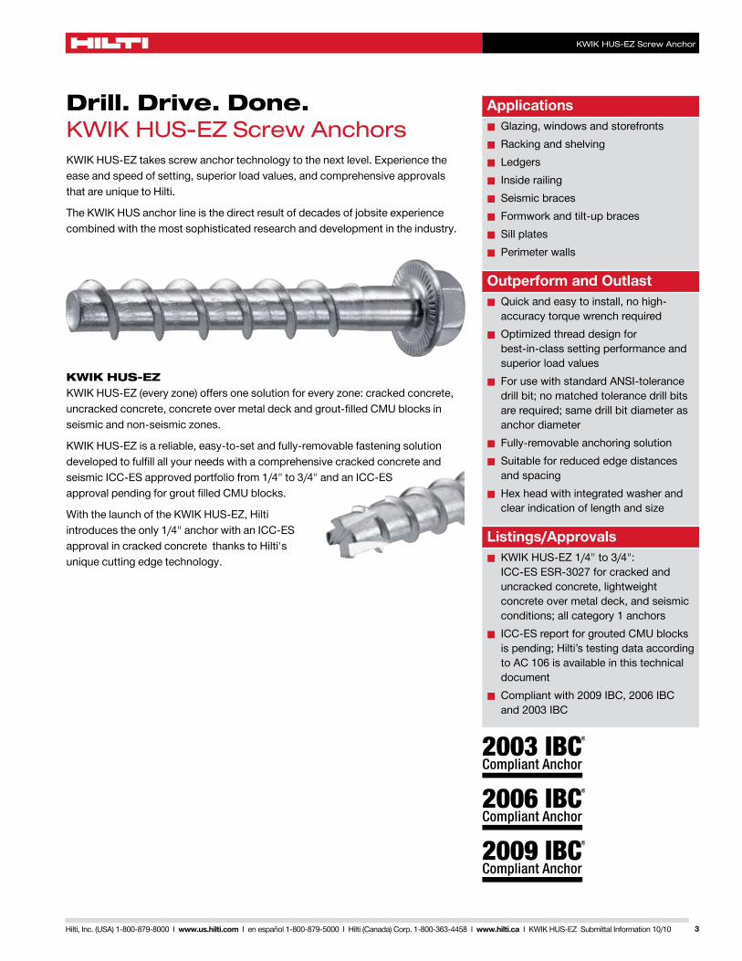
Drill. Drive. Done. KWIK HUS-EZ Screw AnchorsKWIK HUS-EZ takes screw anchor technology to the next level. Experience the ease and speed of setting, superior load values, and comprehensive approvals that are unique to Hilti.
The KWIK HUS anchor line is the direct result of decades of jobsite experience combined with the most sophisticated research and development in the industry.
KWIK HUS-EZ KWIK HUS-EZ (every zone) offers one solution for every zone: cracked concrete, uncracked concrete, concrete over metal deck and grout-filled CMU blocks in seismic and non-seismic zones.
KWIK HUS-EZ is a reliable, easy-to-set and fully-removable fastening solution developed to fulfill all your needs with a comprehensive cracked concrete and seismic ICC-ES approved portfolio from 1/4" to 3/4" and an ICC-ES approval pending for grout filled CMU blocks.
With the launch of the KWIK HUS-EZ, Hilti introduces the only 1/4" anchor with an ICC-ES approval in cracked concrete thanks to Hilti's unique cutting edge technology.
Hilti, Inc. (USA) 1-800-879-8000 I www.us.hilti.com I en español 1-800-879-5000 I Hilti (Canada) Corp. 1-800-363-4458 I www.hilti.ca I KWIK HUS-EZ Submittal Information 10/104
KWIK HUS-EZ Screw Anchor
Hilti. Outperform. Outlast.
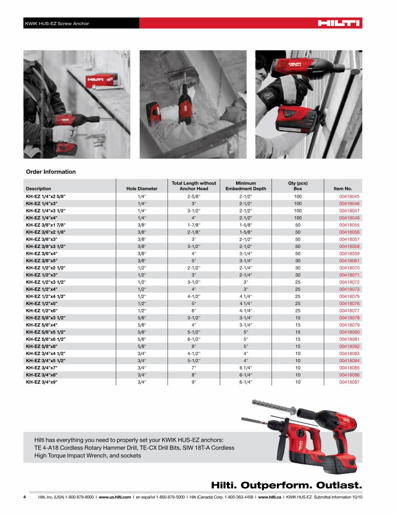
Hilti has everything you need to properly set your KWIK HUS-EZ anchors: TE 4-A18 Cordless Rotary Hammer Drill, TE-CX Drill Bits, SIW 18T-A Cordless High Torque Impact Wrench, and sockets
Hilti, Inc. (USA) 1-800-879-8000 I www.us.hilti.com I en español 1-800-879-5000 I Hilti (Canada) Corp. 1-800-363-4458 I www.hilti.ca I KWIK HUS-EZ Submittal Information 10/10
Mechanical Anchoring Systems
KWIK HUS-EZ Screw Anchor System
5
The following, through page 9, represent a reprint of ICC-ESR 3027.
HILTI KWIK HUS-EZ (KH-EZ) CARBON STEEL SCREW ANCHORS FOR USE IN CRACKED AND UNCRACKED CONCRETE
1.0 EVALUATION SCOPECompliance with the following codes:• 2009 International Building Code®
(2009 IBC)• 2009 International Residential Code®
(2009 IRC)• 2006 International Building Code®
(2006 IBC)• 2006 International Residential Code®
(2006 IRC)• 2003 International Building Code®
(2003 IBC)• 2003 International Residential Code®
(2003 IRC)
Properties evaluated:Structural
2.0 USESThe Hilti KWIK HUS-EZ (KH-EZ) screw anchors are used to resist static, wind and seismic tension and shear loads in cracked and uncracked normal-weight and sand lightweight concrete having a specified strength, f′c, of 2,500 psi to 8,500 psi (17.2 MPa to 58.6 MPa); and cracked and uncracked normal-weight or sand-lightweight concrete over steel deck having a minimum specified compressive strength, f′c of 3,000 psi (20.7 MPa).
The Hilti Kwik HUS EZ screw anchors are an alternative to anchors described in Sections 1911 and 1912 of the 2009 and 2006 IBC and Sections 1912 and 1913 of the 2003 IBC. The anchors may also be used where an engineered design is submitted in accordance with Section R301.1.3 of the IRC.
3.0 DESCRIPTION3.1 KWIK HUS-EZ:
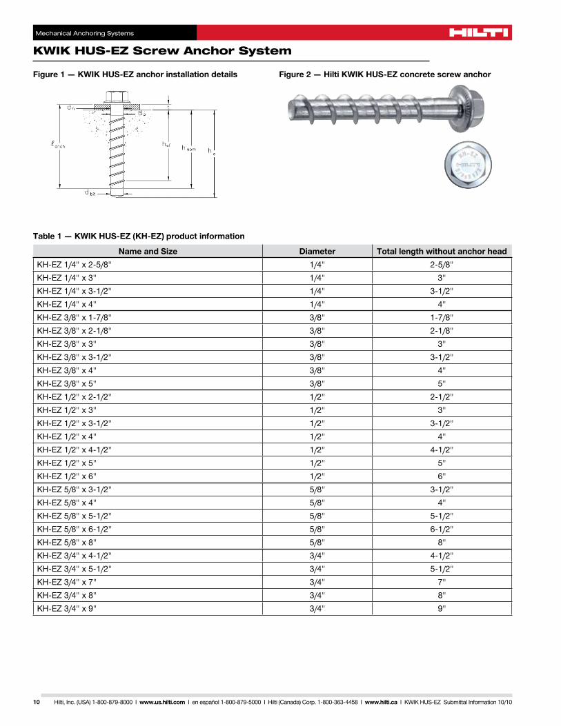
Hilti KWIK HUS-EZ (KH-EZ) anchors are comprised of a body with hex washer head. The anchor is manufactured from carbon steel and is heat treated. It has a minimum 0.0003 inch (8 μm) zinc coating in accordance with DIN EN ISO 4042. The anchoring system is available in a variety of lengths with diameters of 1/4 inch, 3/8 inch, 1/2 inch, 5/8 inch and 3/4 inch (6.4mm, 9.5mm, 12.7mm, 15.9mm and 19.1mm). The KWIK HUS-EZ is illustrated in Figure 1.
The hex head is larger than the diameter of the anchor and is formed with serrations on the underside. The anchor body is formed with threads running most of the length of the anchor body. The anchor is installed in a predrilled hole with a powered impact wrench or torque wrench. The anchor threads cut into the concrete on the sides of the hole and interlock with the base material during installation.
3.2 Concrete:
Normal-weight and lightweight concrete must conform to Sections 1903 and 1905 of the IBC.
3.3 Steel Deck Panels:
Steel deck panels must comply with the configurations in Figure 3 and have a minimum base steel thickness of 0.035 in. (.889 mm). Steel must comply with ASTM A 653/A 653M SS Grade 33 and have a minimum yield strength of 33,000 psi (228 MPa).
4.0 DESIGN AND INSTALLATION4.1 Strength Design:
4.1.1 General: Design strength of anchors complying with the 2009 and 2003 IBC and Section R301.1.3 of the 2009 and 2003 IRC must be determined in accordance with ACI 318-08 Appendix D and this report. Design strength of anchors complying with the 2006 IBC and 2006 IRC must be in accordance with ACI 318-05 Appendix D and this report. Design parameters provided in
Table 2 through Table 5 of this report are based on the 2009 IBC (ACI 318-08) unless noted otherwise in Section 4.1.1 through 4.1.12 of this report.
The strength design of anchors must comply with ACI 318 D.4.1, except as required in ACI 318 D.3.3. Strength reduction factors, Φ, as given in ACI 318 D.4.4, and noted in Tables 3 and 4 of this report, must be used for load combinations calculated in accordance with Section 1605.2.1 of the IBC and Section 9.2 of ACI 318. Strength reduction factors, Φ, as given in ACI 318 D.4.5 must be used for load combinations calculated in accordance with ACI 318 Appendix C. The value of f′
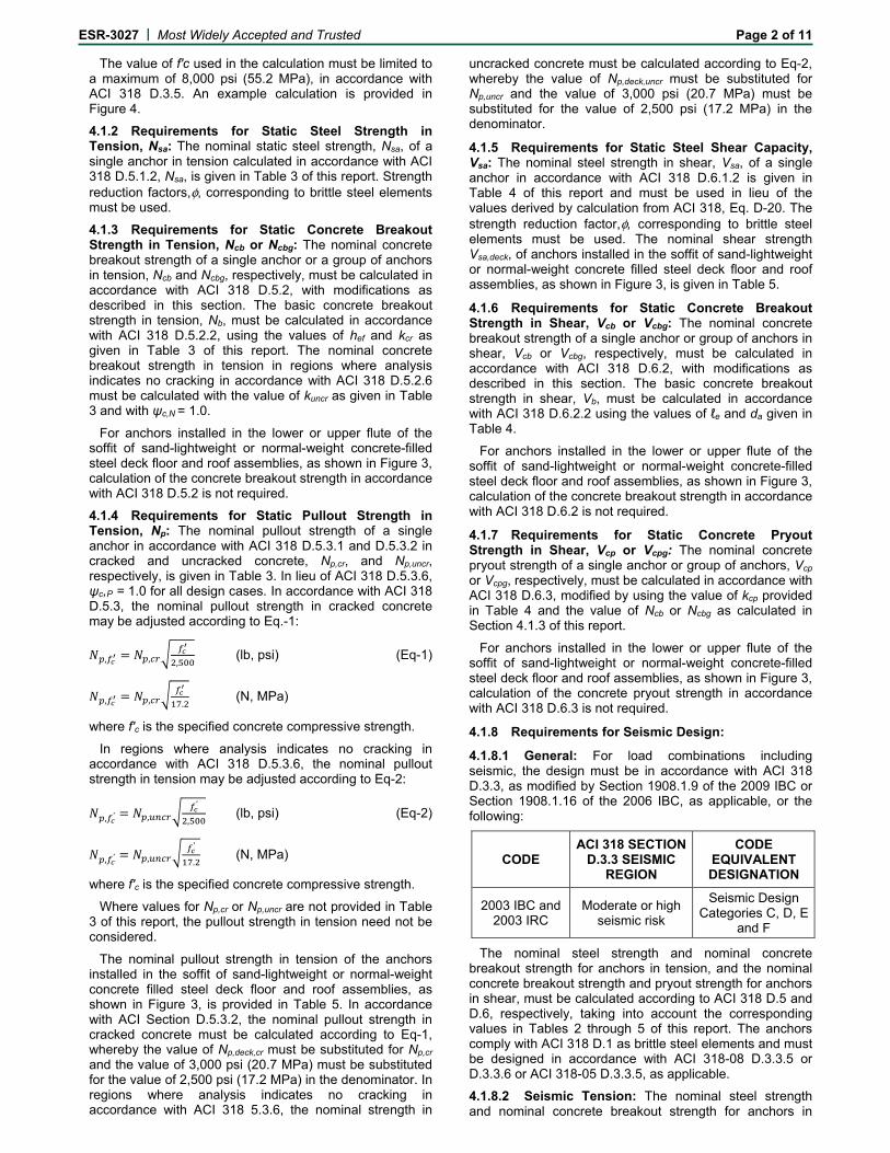
c used in the calculation must be limited to a maximum of 8,000 psi (55.2 MPa), in accordance with ACI 318 D.3.5. An example calculation is provided in Figure 4.
4.1.2 Requirements for Static Steel Strength in Tension, Nsa: The nominal static steel strength, Nsa, of a single anchor in tension calculated in accordance with ACI 318 D.5.1.2, Nsa, is given in Table 3 of this report. Strength reduction factors, Φ, corresponding to brittle steel elements must be used.
4.1.3 Requirements for Static Concrete Breakout Strength in Tension, Ncb or Ncbg: The nominal concrete breakout strength of a single anchor or a group of anchors in tension, Ncb and Ncbg respectively, must be calculated in accordance with ACI 318 D.5.2.2, with modifications as described in this section. The basic concrete breakout strength in tension, Nb, must be calculated in accordance with ACI 318 D.5.2, using the values of hef and kcr as given in Table 3 of this report. The nominal concrete breakout strength in tension in regions where analysis indicates no cracking in accordance with ACI 318 D.5.2.6 must be calculated with the value of kuncr as given in Table 3 and with ψc,N = 1.0.
For anchors installed in the lower or upper
Hilti, Inc. (USA) 1-800-879-8000 I www.us.hilti.com I en español 1-800-879-5000 I Hilti (Canada) Corp. 1-800-363-4458 I www.hilti.ca I KWIK HUS-EZ Submittal Information 10/10
Mechanical Anchoring Systems
KWIK HUS-EZ Screw Anchor System
6
flute of the soffit of sand-lightweight or normal-weight concrete-filled steel deck floor and roof assemblies, as shown in Figure 3, calculation of the concrete breakout strength in accordance with ACI 318 D.5.2 is not required.
4.1.4 Requirements for Static Pullout Strength in Tension, Np: The nominal pullout strength of a single anchor in accordance with ACI D.5.3.1 and D.5.3.2 in cracked and uncracked concrete, Np,cr, and Np,uncr, respectively, is given in Table 3. In lieu of ACI 318 D.5.3.6, ψc,P = 1.0 for all design cases. In accordance with ACI 318 D.5.3, the nominal pullout strength in cracked concrete may be adjusted according to Eq.-1:
f′c Np,f′c
= Np,cr √______ (lb,psi) (Eq-1)
2,500
f′c Np,f′c
= Np,cr √______ (N, MPa)
17.2
where f′c is the specified concrete compressive strength.
In regions where analysis indicates no cracking in accordance with ACI 318 Section D.5.3.6, the nominal pullout strength in tension may be adjusted according to Eq-2:
f′c Np,f′c
= Np,uncr √______ (lb,psi) (Eq-2)
2,500
f′c Np,f′c
= Np,uncr √______ (N, MPa)
17.2
where f′c is the specified concrete compressive strength.
Where values for Np,cr or Np,uncr are not provided in Table 3 of this report, the pullout strength in tension need not be considered.
The nominal pullout strength in tension of the anchors installed in the soffit of sand-lightweight or normal-weight concrete filled steel deck floor and roof assemblies, as shown in Figure 3, is provided in Table 5. In accordance with ACI Section D.5.3.2, the nominal pullout
strength in cracked concrete must be calculated according to Eq-1, whereby the value of Np,deck,cr must be substituted for Np,cr and the value of 3,000 psi (20.7 MPa) must be substituted for the value of 2,500 psi (17.2 MPa) in the denominator. In regions where analysis indicates no cracking in accordance with ACI 318 Section 5.3.6, the nominal strength in uncracked concrete must be calculated according to Eq-2, whereby the value of Np,deck,uncr must be substituted for Np,uncr and the value of 3,000 psi (20.7) MPa must be substituted for the value of 2,500 psi (17.2 MPa) in the denominator.
4.1.5 Requirements for Static Steel Shear Capacity, Vsa: The nominal steel strength in shear, Vsa, of a single anchor in accordance with ACI 318 D.6.1.2 is given in Table 4 of this report and must be used in lieu of the values derived by calculation from ACI 318, Eq. D-20. The strength reduction factor, Φ, corresponding to brittle steel elements must be used. The nominal shear strength of Vsa,deck of anchors installed in the soffit of sand-lightweight or normal-weight concrete filled steel deck floor and roof assemblies, as shown in Figure 3, is given in Table 5.
4.1.6 Requirements for Static Concrete Breakout Strength in Shear, Vcb or Vcbg: The nominal concrete breakout strength of a single anchor or group of anchors in shear, Vcb or Vcbg, respectively, must be calculated in accordance with ACI 318 D.6.2, with modifications as described in this section. The basic concrete breakout strength in shear, Vb, must be calculated in accordance with ACI 318 D.6.2.2 using the values of ℓe and da given in Table 4.
For anchors installed in the lower or upper flute of the soffit of sand-lightweight or normal-weight concrete-filled steel deck floor and roof assemblies, as shown in Figure 3, calculation of the concrete breakout strength in accordance with ACI 318 D.6.2 is not required.
4.1.7 Requirements for Static Concrete Pryout Strength in Shear, Vcp or Vcpg: The nominal concrete pryout strength of a single anchor or group of anchors, Vcp or Vcpg, respectively, must be calculated in accordance with ACI 318 D.6.3, modified by using the value of kcp provided in Table 4 and the value of Ncb or Ncbg as calculated in Section 4.1.3 of this report.
For anchors installed in the lower or upper flute of the soffit of sand-lightweight or normal-weight concrete-filled steel deck floor and roof assemblies, as shown in Figure 3, calculation of the concrete pryout strength in accordance with ACI 318 D.6.3 is not required.
4.1.8 Requirements for Seismic Design
4.1.8.1 General: For load combinations including seismic, the design must be in accordance with ACI 318 Section D.3.3, as modified by Section 1908.1.9 of the 2009 IBC or Section 1908.1.16 of the 2006 IBC, as applicable, or the following:
CODE ACI 318 SECTION
D.3.3 SEISMIC REGION
CODE EQUIVALENT
DESIGNATION
2003 IBC and
2003 IRC
Moderate or high seismic
risk
Seismic Design Categories C,
D, E and F
The nominal steel strength and nominal concrete breakout strength for anchors in tension, and the nominal concrete breakout strength and pryout strength for anchors in shear, must be calculated according to ACI 318 Sections D.5 and D.6, respectively, taking into account the corresponding values in Tables 2 through 5 of this report. The anchors comply with ACI 318 Section D.1 as brittle steel elements and must be designed in accordance with ACI 318-08 Section D.3.3.5 or D.3.3.6 or ACI 318-05 D.3.3.5, as applicable.
Hilti, Inc. (USA) 1-800-879-8000 I www.us.hilti.com I en español 1-800-879-5000 I Hilti (Canada) Corp. 1-800-363-4458 I www.hilti.ca I KWIK HUS-EZ Submittal Information 10/10
Mechanical Anchoring Systems
KWIK HUS-EZ Screw Anchor System
7
4.1.8.2 Seismic Tension: The nominal steel strength and nominal concrete breakout strength for anchors in tension must be calculated according to ACI 318 Section D.5.1 and D.5.2, as described in Sections 4.1.2 and 4.1.3 of this report. In accordance with ACI 318 Section D.5.3.2, the appropriate value for pullout strength in tension for seismic loads, Neq or Np,deck,cr described in Table 3 and 5, respectively, of this report must be used in lieu of Np. Neq or Np,deck,cr may be adjusted by calculations for concrete compressive strength in accordance with Eq-1 of this report in addition for concrete-filled steel deck floor and roof assemblies the value of 3,000 psi (20.7 MPa) must be substituted for the value of 2,500 psi (17.2 MPa) in the denominator.
Where values for Neq are not provided in Table 3 of this report, the pullout strength in tension for seismic loads need not be evaluated.
4.1.8.3 Seismic Shear: The nominal concrete breakout strength and pryout strength in shear must be calculated according to ACI 318 Sections D.6.2 and D.6.3, as described in Sections 4.1.6 and 4.1.7 of this report; and, in accordance with ACI 318 Section D.6.1.2, the appropriate value for nominal steel strength for seismic loads, Vsa,eq or Vsa,deck,eq described in Table 4 and 5, respectively, of this report, must be used in lieu of Vsa.
4.1.9 Requirements for Interaction of Tensile and Shear Forces: The effects of combined tensile and shear forces must be determined in accordance with ACI 318, D.7.
4.1.10 Requirements for Minimum Member Thickness, Minimum Anchor Spacing and Minimum Edge Distance: In lieu of ACI 318 D.8.1 and D.8.3, values of cmin and smin as given in Table 2 of this report must be used. In lieu of ACI 318 Section D.8.5, minimum member thicknesses, hmin as given in Table 3 of this report must be used.
For anchors installed through the soffit of steel deck assemblies, the anchors must be installed in accordance with Figure 3 and shall have an axial spacing along the flute equal to the greater of 3 hef or 1.5 times the flute width.
4.1.11 Requirements for Critical Edge Distance, cac: In applications where c<cac and supplemental reinforcement to control splitting of the concrete is not present, the concrete breakout strength in tension for uncracked concrete, calculated according to ACI 318 Section D.5.2, must be further multiplied by the factor ψcp,N as given by Eq-3:
c
ψcp,N = ____ (Eq-3)
cac
where the factor ψcp,N need not be taken as less than
1.5 hef______
cac
For all other cases, ψcp,N = 1.0. In lieu of using ACI 318 D.8.6, values of cac must comply with Table 3.
4.1.12 Sand-lightweight Concrete: For ACI 318-08, when anchors are used in sand-lightweight concrete, the modification factor for concrete breakout, λ, must be taken as 0.6. In addition, the pullout strength Np,uncr, Np,cr, and Neq must be multiplied by 0.6, as applicable.
For ACI 318-05 the values Nb, Np,uncr, Np,cr, Neq, and Vb determined in accordance with this report must be multiplied by 0.60, in lieu of ACI 318 D.3.4.
For anchors installed in the lower or upper flute of the soffit of sand-lightweight concrete-filled steel deck and floor and roof assemblies, this reduction is not required.
4.2 Allowable Stress Design (ASD):
4.2.1 General: Design values for
use with allowable stress design load combinations calculated in accordance with Section 1605.3 of the IBC must be established using the following equations:
ΦNnTallowable,ASD = _____ (Eq-4)
α
ΦVnVallowable,ASD = _____ (Eq-5)
α
where:
Tallowable,ASD = Allowable tension load (lb, N)
Vallowable ASD = Allowable shear load (lb, N)
ΦNn = Lowest design strength of an anchor or anchor group in tension as determined in accordance with ACI 318 Appendix D, Section 4.1 of this report and the 2009 IBC Section 1908.1.9 or 2006 IBC Section 1908.1.16, as applicable.
ΦVn = Lowest design strength of an anchor or anchor group in shear as determined in accordance with ACI 318 Appendix D, Section 4.1 of this report and the 2009 IBC Section 1908.1.9 or 2006 IBC Section 1908.1.16, as applicable.
α = Conversion factor calculated as a weighted average of the load factors for the controlling load combination. In addition, α must include all applicable factors e.g. to account for nonductile failure modes and required over-strength.
Limits on edge distance, anchor spacing and member thickness as given in Table 2 of this report must apply. An example of Allowable Stress Design tension values is given in Table 6 and Figure 4.
4.2.2 Interaction of Tensile and Shear Forces: The interaction must be calculated and consistent with ACI 318 D.7, as follows:
Hilti, Inc. (USA) 1-800-879-8000 I www.us.hilti.com I en español 1-800-879-5000 I Hilti (Canada) Corp. 1-800-363-4458 I www.hilti.ca I KWIK HUS-EZ Submittal Information 10/10
Mechanical Anchoring Systems
KWIK HUS-EZ Screw Anchor System
8
For shear loads V ≤ 0.2 Vallowable,ASD, the full allowable load in tension Tallowable,ASD must be permitted.
For tension loads T ≤ 0.2 Tallowable,ASD, the full allowable load in shear Vallowable,ASD must be permitted.
Installation parameters are provided in Tables 1 and 2 and Figures 1, 3 and 5. Anchor locations must comply with this report and plans and specifications approved by the code official. The Hilti KWIK HUS-EZ (KH-EZ) must be installed according to manufacturer’s published instructions and this report. In case of conflict this report governs. Anchors must be installed in holes drilled into concrete perpendicular to the surface using carbide-tipped masonry drill bits complying with ANSI B212.15-1994. The nominal drill bit diameter must be equal to that of the anchor. The minimum drilled hole depth is given in Table 2. Prior to installation, dust and debris must be removed from the drilled hole using a hand pump, compressed air or a vacuum. The anchor must be installed into the predrilled hole using a powered impact wrench or installed with a torque wrench until the proper nominal embedment depth is obtained. The maximum impact wrench torque, T
impact,max and maximum installation torque, Tinst,max for the manual torque wrench must be in accordance with Table 2. The KWIK HUS-EZ (KH-EZ) may be loosened by a maximum of one turn and reinstalled with a socket wrench or powered impact wrench to facilitate fixture attachment or realignment.
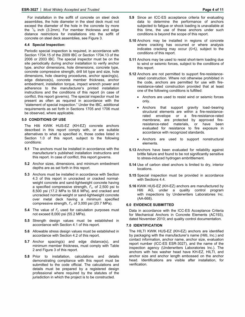
For installation in the soffit of concrete on steel deck assemblies, the hole diameter in the steel deck must not exceed the diameter of the hole in the concrete by more the 1/8 inch (3.2mm). For member thickness and edge
distance restrictions for installations into the soffit of concrete on steel deck assemblies, see Figure 3.
4.4 Special Inspection:
Periodic special inspection is required, in accordance with Section 1704.15 of the 2009 IBC or Section 1704.13 of the 2006 or 2003 IBC. The special inspector must be on the site periodically during anchor installation to verify anchor type, anchor dimensions, hole dimensions, concrete type, concrete compressive strength, drill bit type and size, hole dimensions, hole cleaning procedures, anchor spacing(s), edge distance(s), concrete member thickness, anchor embedment, installation torque, impact wrench power and adherence to the manufacturer’s printed installation instructions and the conditions of this report, in case of conflict this report governs. The special inspector must be present as often as required in accordance with the “statement of special inspection.” Under the IBC, additional requirements as set forth in Sections 1705 and 1706 must be observed, where applicable.
5.0 CONDITIONS OF USEThe Hilti KWIK HUS-EZ (KH-EZ) concrete anchors described in this report comply with, or are suitable alternatives to what is specified in, those codes listed in Section 1.0 of this report, subject to the following conditions:
5.1 The anchors must be installed in accordance with the manufacturer’s published installation instructions and this report. In case of conflict, this report governs.
5.2 Anchor sizes, dimensions, and minimum embedment depths are as set forth in this report.
5.3 Anchors must be installed in accordance with section 4.3 of this report in uncracked or cracked normal-weight concrete and sand lightweight concrete having a
specified compressive strength of f′
c of 2,500 psi to 8,500 psi (17.2 MPa to 58.6 MPa) and cracked and uncracked normal-weight or sand lightweight concrete over metal deck having a minimum specified compressive strength f′c of 3,000 psi (20.7 MPa).
5.4 The values of f’c used for calculation purposes must not exceed 8,000 psi (55.2 MPa).
5.6 Strength design values must be established in accordance with Section 4.1 of this report.
5.7 Allowable stress design values must be established in accordance with Section 4.2 of this report.
5.8 Anchor spacing(s) and edge distance(s), and minimum member thickness must comply with Table 2 and Figure 3 of this report.
5.9 Prior to installation, calculations and details demonstrating compliance with this report must be submitted to the code official. The calculations and details must be prepared by a registered design professional where required by the statutes of the jurisdiction in which the project is to be constructed.
5.10 Since an ICC-ES acceptance criteria for evaluating data to determine the performance of anchors subjected to fatigue or shock loading is unavailable at this time, the use of these anchors under such conditions is beyond the scope of this report.
5.11 Anchors may be installed in regions of concrete where cracking has occurred or where analysis indicates cracking may occur (f
t > fr), subject to the conditions of this report.
5.12 Anchors may be used to resist short-term loading due to wind or seismic forces, subject to the conditions of this report.
Hilti, Inc. (USA) 1-800-879-8000 I www.us.hilti.com I en español 1-800-879-5000 I Hilti (Canada) Corp. 1-800-363-4458 I www.hilti.ca I KWIK HUS-EZ Submittal Information 10/10
Mechanical Anchoring Systems
KWIK HUS-EZ Screw Anchor System
9
• Anchors are not permitted to support fire-resistance-rated construction. Where not otherwise prohibited in the code, anchors are permitted for use with fire-resistance-rated construction provided that at least one of the following conditions is fulfilled:
• Anchors are used to resist wind or seismic forces only.
• Anchors that support gravity load-bearing structural elements are within a fire-resistance-rated envelope or a fire-resistance-rated membrane, are protected by approved fire-resistance-rated materials, or have been evaluated for resistance to fire exposure in accordance with recognized standards.
• Anchors are used to support nonstructural elements.
5.13 Anchors have been evaluated for reliability against brittle failure and found to be not significantly sensitive to stress-induced hydrogen embrittlement.
5.14 Use of carbon steel anchors is limited to dry, interior locations.
5.15 Special inspection must be provided in accordance with Section 4.4.
5.16 KWIK HUS EZ (KH-EZ) anchors are manufactured by Hilti AG, under a quality control program with inspections by Underwriters Laboratories Inc. (AA-668).
6.0 EVIDENCE SUBMITTED Data in accordance with the ICC-ES Acceptance Criteria for Mechanical Anchors in Concrete Elements (AC193), dated November 2010; and quality control documentation.
7.0 IDENTIFICATIONThe HILTI KWIK HUS-EZ (KH-EZ) anchors are identified by packaging with the manufacturer’s name (Hilti, Inc.) and contact information, anchor name, anchor size, evaluation report number (ICC-ES ESR-3027), and the name of the inspection agency (Underwriters Laboratories, Inc.). The anchors with hex washer head have the letters KH-EZ, HILTI and anchor size and anchor length embossed on the anchor head. Identifications are visible after installation for verification.
Hilti, Inc. (USA) 1-800-879-8000 I www.us.hilti.com I en español 1-800-879-5000 I Hilti (Canada) Corp. 1-800-363-4458 I www.hilti.ca I KWIK HUS-EZ Submittal Information 10/10
Name and Size Diameter Total length without anchor headKH-EZ 1/4" x 2-5/8" 1/4" 2-5/8"KH-EZ 1/4" x 3" 1/4" 3"KH-EZ 1/4" x 3-1/2" 1/4" 3-1/2"KH-EZ 1/4" x 4" 1/4" 4"KH-EZ 3/8" x 1-7/8" 3/8" 1-7/8"KH-EZ 3/8" x 2-1/8" 3/8" 2-1/8"KH-EZ 3/8" x 3" 3/8" 3"KH-EZ 3/8" x 3-1/2" 3/8" 3-1/2"KH-EZ 3/8" x 4" 3/8" 4"KH-EZ 3/8" x 5" 3/8" 5"KH-EZ 1/2" x 2-1/2" 1/2" 2-1/2"KH-EZ 1/2" x 3" 1/2" 3"KH-EZ 1/2" x 3-1/2" 1/2" 3-1/2"KH-EZ 1/2" x 4" 1/2" 4"KH-EZ 1/2" x 4-1/2" 1/2" 4-1/2"KH-EZ 1/2" x 5" 1/2" 5"KH-EZ 1/2" x 6" 1/2" 6"KH-EZ 5/8" x 3-1/2" 5/8" 3-1/2"KH-EZ 5/8" x 4" 5/8" 4"KH-EZ 5/8" x 5-1/2" 5/8" 5-1/2"KH-EZ 5/8" x 6-1/2" 5/8" 6-1/2"KH-EZ 5/8" x 8" 5/8" 8"KH-EZ 3/4" x 4-1/2" 3/4" 4-1/2"KH-EZ 3/4" x 5-1/2" 3/4" 5-1/2"KH-EZ 3/4" x 7" 3/4" 7"KH-EZ 3/4" x 8" 3/4" 8"KH-EZ 3/4" x 9" 3/4" 9"
Hilti, Inc. (USA) 1-800-879-8000 I www.us.hilti.com I en español 1-800-879-5000 I Hilti (Canada) Corp. 1-800-363-4458 I www.hilti.ca I KWIK HUS-EZ Submittal Information 10/10
Mechanical Anchoring Systems
KWIK HUS-EZ Screw Anchor System
11
Table 2 — KWIK HUS-EZ (KH-EZ) installation information and anchor specification1
Characteristic Symbol UnitsNominal Anchor Diameter (inches)
For SI: 1 inch = 25.4 mm, 1 ft-lbf = 1.356 N-m, 1 psi = 6.89 Pa, 1 in2 = 645 mm2, 1 lb/in = 0.175 N/mm
1 The data presented in this table is to be used in conjunction with the design criteria of ACI 318 Appendix D.
2 For installations through the soffit of steel deck into concrete (see Figure 3) anchors installed in the lower flute may be installed with a maximum 1 inch offset in either direction from the center of the flute.
3 Because of variability in measurement procedures, the published torque of an impact tool may not correlate properly with the above setting torques. Over-torquing can damage the anchor and/or reduce its holding capacity.
4 Tinst,max applies to installations using a calibrated torque wrench.
5 The notation in parenthesis is for the 2006 IBC.
6 The notation in parenthesis is for the 2003 IBC.
* Values courtesy of ICC evaluation report.
Hilti, Inc. (USA) 1-800-879-8000 I www.us.hilti.com I en español 1-800-879-5000 I Hilti (Canada) Corp. 1-800-363-4458 I www.hilti.ca I KWIK HUS-EZ Submittal Information 10/10
Reduction Factor for Pullout Strength2 (2,500 psi)
Φeq- 0.65 (Condition B)
Axial Stiffness in Service Load RangeUncracked Concrete βuncr lb/in.
760,000
Cracked Concrete βcr293,000
For SI: 1 inch = 25.4 mm, 1 ft-lbf = 1.356 N-m, 1 psi = 6.89 Pa, 1 in2 = 645 mm2, 1 lb/in = 0.175 N/mm
1 The data in this table is intended for use with the design provisions of ACI 318 Appendix D; for anchors resisting seismic load combinations the additional requirements of D.3.3 shall apply.
2 Values of Φ in this table applies when the load combinations for ACI 318 Section 9.2, IBC Section 1605.2.1 are used and the requirements of ACI 318 D.4.4 for Condition B are met. If the load combinations of ACI 318 Appendix C are used, the appropriate value of Φ must be used. For situations where reinforcement meets the requirements of Condition A, ACI 318 Section D.4.4 provides the appropriate φ factor.
3 In this report, N/A denotes that pullout resistance does not govern and does not need to be considered.
4 The characteristic pullout resistance for concrete compressive strengths greater than 2500 psi may be increased by multiplying the value in the table by (f′c /2,500)1/2 for psi or (f′c /17.2)1/2 for MPa.
5 For sand-lightweight concrete, calculate values according to Section 4.1.12 of this report.
Hilti, Inc. (USA) 1-800-879-8000 I www.us.hilti.com I en español 1-800-879-5000 I Hilti (Canada) Corp. 1-800-363-4458 I www.hilti.ca I KWIK HUS-EZ Submittal Information 10/10
in. 2-1/2 1-5/8 2-1/2 3-1/4 2-1/4 3 4-1/4 3-1/4 5 4 6-1/4Steel Strength in Shear (ACI 318 D 6.1)4, 5
Shear Resistance of Steel — Static
Vsa 3 lb. 1548 4057 5185 9245 11221 16662
Shear Resistance of Steel — Seismic
Veq 3 lb. 1393 2524 3111 5547 6733 11556
Reduction Factor for Steel Strength
Φsa- 0.60
Concrete Breakout Strength in Shear (ACI 318 D.6.2)Nominal Diameter do (do)
6 in. 0.250 0.375 0.500 0.625 0.750Load Bearing Length of Anchor
le 3 in. 1.92 1.11 1.86 2.50 1.52 2.16 3.22 2.39 3.88 2.92 4.84
Reduction Factor for Concrete Breakout Strength
Φcb - 0.70
Concrete Pryout Strength in Shear (ACI 318 D.6.3)Coefficient for Pryout Strength
kcp- 1.0 1.0 1.0 2.0 1.0 1.0 2.0 1.0 2.0 2.0 2.0
Reduction Factor for Pryout Strength
Φcp- 0.70
For SI: 1 inch = 25.4 mm, 1 ft-lbf = 1.356 N-m, 1 psi = 6.89 Pa, 1 in2 = 645 mm2, 1 lb/in = 0.175 N/mm
1 The data in this table is intended for use with the design provisions of ACI 318 Appendix D
2 Values of ф in this table applies when the load combinations for ACI 318 Section 9.2, IBC Section 1605.2.1 are used and the requirements of ACI 318 D.4.4 for Condition B are met. If the load combinations of ACI 318 Appendix C are used, the appropriate value of ф must be used. For situations where reinforcement meets the requirements of Condition A, ACI 318 D.4.4 provides the appropriate ф factor.
3 For 2003 IBC code basis replace ℓe with ℓ , Vsa with Vs, and Veq with Vsa,seis.
4 Reported values for steel strength in shear are based on test results per ACI 355.2, Section 9.4 and must be used for design in lieu of calculated results using equation D-20 of ACI 318.
5 The KWIK HUS-EZ (KH-EZ) is considered a brittle steel element as defined by ACI 318 D.1.
6 The notation in brackets is for the 2006 IBC.
Hilti, Inc. (USA) 1-800-879-8000 I www.us.hilti.com I en español 1-800-879-5000 I Hilti (Canada) Corp. 1-800-363-4458 I www.hilti.ca I KWIK HUS-EZ Submittal Information 10/10
Mechanical Anchoring Systems
KWIK HUS-EZ Screw Anchor System
14
Table 5 — Hilti KWIK HUS-EZ (KH-EZ) tension and shear design data for installation in the underside of concrete-filled profile steel deck assemblies1,6
Characteristic Symbol UnitsLower Flute Upper Flute
1 Installation must comply with Sections 4.1.10 and 4.3 and Figure 3 of this report.
2 The values listed must be used in accordance with Section 4.1.4 of this report.
3 The values listed must be used in accordance with Section 4.1.4 and 4.1.8.2 of this report.
4 The values listed must be used in accordance with Section 4.1.5 and 4.1.8.3 of this report.
5 The values for фp in tension can be found in Table 3 of this report and the values for фsa in shear can be found in Table 4 of this report.
6 The characteristic pullout resistance for concrete compressive strengths greater than 2,500 psi may be increased by multiplying the value in the table by (f′c/3,000)1/2 for psi or (f′c/20.7)1/2 for MPa.
Figure 3 — Installation of KWIK HUS-EZ (KH-EZ) in Soffit of Concrete Over Steel Deck Floor and Roof Assemblies1
1 Anchors may be placed in the upper or lower flute of the steel deck profile provided the minimum hole clearance is satisfied. Anchors in the lower flute may be installed with a maximum 1-inch offset in either direction from the center of the flute. The offset distance may be increased proportionally for profiles with lower flute widths greater than those shown provided the minimum lower flute edge distance is also satisfied.
Hilti, Inc. (USA) 1-800-879-8000 I www.us.hilti.com I en español 1-800-879-5000 I Hilti (Canada) Corp. 1-800-363-4458 I www.hilti.ca I KWIK HUS-EZ Submittal Information 10/10
2 Concrete determined to remain uncracked for the life of the anchorage.
3 Load combinations are taken from ACI 318 Section 9.2 (no seismic loading).
4 40% dead load and 60% live load, controlling load combination 1.2D + 1.6L.
5 Calculation of weighted average for conversion factor α = 1.2(0.4) + 1.6(0.6) = 1.44.
6 f′c = 2,500 psi (normal weight concrete).
7 ca1 = ca2 ≥ cac.
8 h ≥ hmin.
9 Values are for Condition B where supplementary reinforcement in accordance with ACI 318 D.4.4 is not provided.
Hilti, Inc. (USA) 1-800-879-8000 I www.us.hilti.com I en español 1-800-879-5000 I Hilti (Canada) Corp. 1-800-363-4458 I www.hilti.ca I KWIK HUS-EZ Submittal Information 10/10
Mechanical Anchoring Systems
KWIK HUS-EZ Screw Anchor System
16
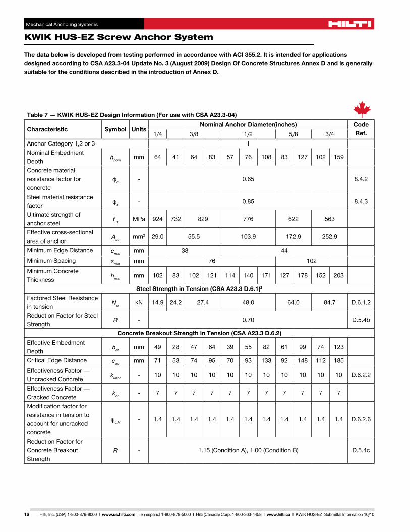
Table 7 — KWIK HUS-EZ Design Information (For use with CSA A23.3-04)
Characteristic Symbol UnitsNominal Anchor Diameter(inches) Code
The data below is developed from testing performed in accordance with ACI 355.2. It is intended for applications designed according to CSA A23.3-04 Update No. 3 (August 2009) Design Of Concrete Structures Annex D and is generally suitable for the conditions described in the introduction of Annex D.
Hilti, Inc. (USA) 1-800-879-8000 I www.us.hilti.com I en español 1-800-879-5000 I Hilti (Canada) Corp. 1-800-363-4458 I www.hilti.ca I KWIK HUS-EZ Submittal Information 10/10
Mechanical Anchoring Systems
KWIK HUS-EZ Screw Anchor System
17
Characteristic Symbol UnitsNominal Anchor Diameter(inches) Code
Ref.1/4 3/8 1/2 5/8 3/4Pullout Strength in Tension — Non Seismic Applications (CSA A23.3 D.6.3)1
Axial Stiffness in Service Load RangeUncracked Concrete ßuncr
lb/in. 760000
Cracked Concrete ßcrlb/in. 293000
Steel Strength in Shear (CSA A23.3 D.7.1)2
Factored Shear Resistance of Steel — Static
VsrkN 3.8 11.1 12.7 22.7 27.6 40.9 D.7.1.2c
Factored Shear Resistance of Steel — Seismic
Vsr,seiskN 3.4 6.2 7.6 13.6 16.5 28.4 D.7.1.2c
Reduction Factor for Steel Strength
R - 0.65 D.5.4b
Concrete Breakout Strength in Shear (CSA A23.3 D.7.2)Nominal Diameter do
mm 6.4 9.5 12.7 15.9 19.1Load Bearing Length of Anchor
le mm 49 28 47 64 39 55 82 61 99 74 123
Reduction Factor for Concrete Breakout Strength
R 1.15 (Condition A), 1.00 (Condition B)
Concrete Pryout Strength in Shear (CSA A23.3 D.7.3)Coefficient for Pryout Strength
kcp1.0 1.0 1.0 2.0 1.0 1.0 2.0 1.0 2.0 2.0 2.0
Reduction Factor for Pryout Strength
R 1.15 (Condition A), 1.00 (Condition B)
1 N/A denotes that pullout resistance does not govern and does not need to be considered.
2 The Kwik HUS-EZ (KH-EZ) is considered a brittle steel element as defined by CSA A23.3 D.2.
This table replaces Table 3 and Table 4 of this Supplement (and Table 3 and Table 4 of ESR-3027) for anchorage design in normal weight concrete in accordance with CSA A23.3-04.
Hilti, Inc. (USA) 1-800-879-8000 I www.us.hilti.com I en español 1-800-879-5000 I Hilti (Canada) Corp. 1-800-363-4458 I www.hilti.ca I KWIK HUS-EZ Submittal Information 10/10
Mechanical Anchoring Systems
KWIK HUS-EZ Screw Anchor System
18
Figure 4 — Example calculation
Given: Two 1/2” diameter KH-EZ with static tension load
hnom = 4.25 incheshef = 3.22 inches
Normal Weight Concrete – f’c = 3,000 psiNo supplementary reinforcement (Cond. B)Assume cracked concrete since no other information is available.
Hilti, Inc. (USA) 1-800-879-8000 I www.us.hilti.com I en español 1-800-879-5000 I Hilti (Canada) Corp. 1-800-363-4458 I www.hilti.ca I KWIK HUS-EZ Submittal Information 10/10
Mechanical Anchoring Systems
KWIK HUS-EZ Screw Anchor System
19
Figure 5 — Installation instructions
!
Drill hole in base material using proper diameter drill bit.
Install anchor using proper impact tool or torque wrench. Fasten anchor tightly against fastened part.
Clean dilled hole to remove debris.
ICC-ES Evaluation Reports are not to be construed as representing aesthetics or any other attributes not specifically addressed, nor are they to be construed as an endorsement of the subject of the report or a recommendation for its use. There is no warranty by ICC Evaluation Service, LLC, express or implied, as to any finding or other matter in this report, or as to any product covered by the report.
ICC-ES Evaluation Report ESR-3027 Issued December 1, 2010
This report is subject to re-examination in one year.
www.icc-es.org | (800) 423-6587 | (562) 699-0543 A Subsidiary of the International Code Council ®
DIVISION: 03 00 00—CONCRETE Section: 03 16 00—Concrete Anchors REPORT HOLDER: HILTI, INC. 5400 SOUTH 122ND EAST AVENUE TULSA, OKLAHOMA 74146 (800) 879-8000 www.us.hilti.com [email protected] EVALUATION SUBJECT: HILTI KWIK HUS-EZ (KH-EZ) CARBON STEEL SCREW ANCHORS FOR USE IN CRACKED AND UNCRACKED CONCRETE 1.0 EVALUATION SCOPE
Compliance with the following codes:
2009 International Building Code® (2009 IBC)
2009 International Residential Code® (2009 IRC)
2006 International Building Code® (2006 IBC)
2006 International Residential Code® (2006 IRC)
2003 International Building Code® (2003 IBC)
2003 International Residential Code® (2003 IRC)
Property evaluated:
Structural
2.0 USES
The Hilti KWIK HUS-EZ (KH-EZ) screw anchors are used to resist static, wind and seismic tension and shear loads in cracked and uncracked normal-weight and sand- lightweight concrete having a specified strength, f′c, of 2,500 psi to 8,500 psi (17.2 MPa to 58.6 MPa); and cracked and uncracked normal-weight or sand-lightweight concrete over steel deck having a minimum specified compressive strength, f′c, of 3,000 psi (20.7 MPa).
The Hilti KWIK HUS-EZ (KH-EZ) screw anchors are an alternative to anchors described in Sections 1911 and 1912 of the 2009 and 2006 IBC and Sections 1912 and 1913 of the 2003 IBC. The anchors may also be used where an engineered design is submitted in accordance with Section R301.1.3 of the IRC.
3.0 DESCRIPTION
3.1 KWIK HUS-EZ (KH-EZ):
Hilti KWIK HUS-EZ (KH-EZ) anchors are comprised of a body with hex washer head. The anchor is manufactured from carbon steel and is heat treated. It has a minimum 0.0003-inch (8 μm) zinc coating in accordance with DIN EN ISO 4042. The anchoring system is available in a variety of lengths with diameters of 1/4 inch, 3/8 inch, 1/2 inch, 5/8 inch and 3/4 inch (6.4 mm, 9.5 mm, 12.7 mm, 15.9 mm and 19.1 mm). The KWIK HUS-EZ (KH-EZ) is illustrated in Figure 1.
The hex head is larger than the diameter of the anchor and is formed with serrations on the underside. The anchor body is formed with threads running most of the length of the anchor body. The anchor is installed in a predrilled hole with a powered impact wrench or torque wrench. The anchor threads cut into the concrete on the sides of the hole and interlock with the base material during installation.
3.2 Concrete:
Normal-weight and lightweight concrete must conform to Sections 1903 and 1905 of the IBC.
3.3 Steel Deck Panels:
Steel deck panels must comply with the configurations in Figure 3 and have a minimum base steel thickness of 0.035 inch (0.889 mm). Steel must comply with ASTM A 653/A 653M SS Grade 33 and have a minimum yield strength of 33,000 psi (228 MPa).
4.0 DESIGN AND INSTALLATION
4.1 Strength Design:
4.1.1 General: Design strength of anchors complying with the 2009 and 2003 IBC and Section R301.1.3 of the 2009 and 2003 IRC must be determined in accordance with ACI 318-08 Appendix D and this report. Design strength of anchors complying with the 2006 IBC and 2006 IRC must be in accordance with ACI 318-05 Appendix D and this report. Design parameters provided in Table 2 through Table 5 of this report are based on the 2009 IBC (ACI 318-08) unless noted otherwise in Sections 4.1.1 through 4.1.12.
The strength design of anchors must comply with ACI 318 D.4.1, except as required in ACI 318 D.3.3. Strength reduction factors, φ, as given in ACI 318 D.4.4, and noted in Tables 3 and 4 of this report, must be used for load combinations calculated in accordance with Section 1605.2.1 of the IBC and Section 9.2 of ACI 318. Strength reduction factors, φ, as given in ACI 318 D.4.5 must be used for load combinations calculated in accordance with ACI 318 Appendix C.
ESR-3027 | Most Widely Accepted and Trusted Page 2 of 11
The value of f′c used in the calculation must be limited to a maximum of 8,000 psi (55.2 MPa), in accordance with ACI 318 D.3.5. An example calculation is provided in Figure 4.
4.1.2 Requirements for Static Steel Strength in Tension, Nsa: The nominal static steel strength, Nsa, of a single anchor in tension calculated in accordance with ACI 318 D.5.1.2, Nsa, is given in Table 3 of this report. Strength reduction factors,φ, corresponding to brittle steel elements must be used.
4.1.3 Requirements for Static Concrete Breakout Strength in Tension, Ncb or Ncbg: The nominal concrete breakout strength of a single anchor or a group of anchors in tension, Ncb and Ncbg, respectively, must be calculated in accordance with ACI 318 D.5.2, with modifications as described in this section. The basic concrete breakout strength in tension, Nb, must be calculated in accordance with ACI 318 D.5.2.2, using the values of hef and kcr as given in Table 3 of this report. The nominal concrete breakout strength in tension in regions where analysis indicates no cracking in accordance with ACI 318 D.5.2.6 must be calculated with the value of kuncr as given in Table 3 and with ψc,N = 1.0.
For anchors installed in the lower or upper flute of the soffit of sand-lightweight or normal-weight concrete-filled steel deck floor and roof assemblies, as shown in Figure 3, calculation of the concrete breakout strength in accordance with ACI 318 D.5.2 is not required.
4.1.4 Requirements for Static Pullout Strength in Tension, Np: The nominal pullout strength of a single anchor in accordance with ACI 318 D.5.3.1 and D.5.3.2 in cracked and uncracked concrete, Np,cr, and Np,uncr, respectively, is given in Table 3. In lieu of ACI 318 D.5.3.6, ψc,P = 1.0 for all design cases. In accordance with ACI 318 D.5.3, the nominal pullout strength in cracked concrete may be adjusted according to Eq.-1:
, = , , (lb, psi) (Eq-1)
, = , . (N, MPa)
where f′c is the specified concrete compressive strength.
In regions where analysis indicates no cracking in accordance with ACI 318 D.5.3.6, the nominal pullout strength in tension may be adjusted according to Eq-2:
, ′ = , ′, (lb, psi) (Eq-2)
, ′ = , ′. (N, MPa)
where f′c is the specified concrete compressive strength.
Where values for Np,cr or Np,uncr are not provided in Table 3 of this report, the pullout strength in tension need not be considered.
The nominal pullout strength in tension of the anchors installed in the soffit of sand-lightweight or normal-weight concrete filled steel deck floor and roof assemblies, as shown in Figure 3, is provided in Table 5. In accordance with ACI Section D.5.3.2, the nominal pullout strength in cracked concrete must be calculated according to Eq-1, whereby the value of Np,deck,cr must be substituted for Np,cr and the value of 3,000 psi (20.7 MPa) must be substituted for the value of 2,500 psi (17.2 MPa) in the denominator. In regions where analysis indicates no cracking in accordance with ACI 318 5.3.6, the nominal strength in
uncracked concrete must be calculated according to Eq-2, whereby the value of Np,deck,uncr must be substituted for Np,uncr and the value of 3,000 psi (20.7 MPa) must be substituted for the value of 2,500 psi (17.2 MPa) in the denominator.
4.1.5 Requirements for Static Steel Shear Capacity, Vsa: The nominal steel strength in shear, Vsa, of a single anchor in accordance with ACI 318 D.6.1.2 is given in Table 4 of this report and must be used in lieu of the values derived by calculation from ACI 318, Eq. D-20. The strength reduction factor,φ, corresponding to brittle steel elements must be used. The nominal shear strength Vsa,deck, of anchors installed in the soffit of sand-lightweight or normal-weight concrete filled steel deck floor and roof assemblies, as shown in Figure 3, is given in Table 5.
4.1.6 Requirements for Static Concrete Breakout Strength in Shear, Vcb or Vcbg: The nominal concrete breakout strength of a single anchor or group of anchors in shear, Vcb or Vcbg, respectively, must be calculated in accordance with ACI 318 D.6.2, with modifications as described in this section. The basic concrete breakout strength in shear, Vb, must be calculated in accordance with ACI 318 D.6.2.2 using the values of ℓe and da given in Table 4.
For anchors installed in the lower or upper flute of the soffit of sand-lightweight or normal-weight concrete-filled steel deck floor and roof assemblies, as shown in Figure 3, calculation of the concrete breakout strength in accordance with ACI 318 D.6.2 is not required.
4.1.7 Requirements for Static Concrete Pryout Strength in Shear, Vcp or Vcpg: The nominal concrete pryout strength of a single anchor or group of anchors, Vcp or Vcpg, respectively, must be calculated in accordance with ACI 318 D.6.3, modified by using the value of kcp provided in Table 4 and the value of Ncb or Ncbg as calculated in Section 4.1.3 of this report.
For anchors installed in the lower or upper flute of the soffit of sand-lightweight or normal-weight concrete-filled steel deck floor and roof assemblies, as shown in Figure 3, calculation of the concrete pryout strength in accordance with ACI 318 D.6.3 is not required.
4.1.8 Requirements for Seismic Design:
4.1.8.1 General: For load combinations including seismic, the design must be in accordance with ACI 318 D.3.3, as modified by Section 1908.1.9 of the 2009 IBC or Section 1908.1.16 of the 2006 IBC, as applicable, or the following:
CODE ACI 318 SECTION
D.3.3 SEISMIC REGION
CODE EQUIVALENT DESIGNATION
2003 IBC and2003 IRC
Moderate or high seismic risk
Seismic Design Categories C, D, E
and F
The nominal steel strength and nominal concrete breakout strength for anchors in tension, and the nominal concrete breakout strength and pryout strength for anchors in shear, must be calculated according to ACI 318 D.5 and D.6, respectively, taking into account the corresponding values in Tables 2 through 5 of this report. The anchors comply with ACI 318 D.1 as brittle steel elements and must be designed in accordance with ACI 318-08 D.3.3.5 or D.3.3.6 or ACI 318-05 D.3.3.5, as applicable.
4.1.8.2 Seismic Tension: The nominal steel strength and nominal concrete breakout strength for anchors in
ESR-3027 | Most Widely Accepted and Trusted Page 3 of 11
tension must be calculated according to ACI 318 D.5.1 and D.5.2, as described in Sections 4.1.2 and 4.1.3 of this report. In accordance with ACI 318 D.5.3.2, the appropriate value for pullout strength in tension for seismic loads, Neq or Np,deck,cr described in Table 3 and 5, respectively, of this report must be used in lieu of Np. Neq or Np,deck,cr may be adjusted by calculations for concrete compressive strength in accordance with Eq-1 of this report in addition for concrete-filled steel deck floor and roof assemblies the value of 3,000 psi (20.7 MPa) must be substituted for the value of 2,500 psi (17.2 MPa) in the denominator. Where values for Neq are not provided in Table 3 of this report, the pullout strength in tension for seismic loads need not be evaluated.
4.1.8.3 Seismic Shear: The nominal concrete breakout strength and pryout strength in shear must be calculated according to ACI 318 D.6.2 and D.6.3, as described in Sections 4.1.6 and 4.1.7 of this report. In accordance with ACI 318 D.6.1.2, the appropriate value for nominal steel strength for seismic loads, Veq or Vsa,deck,eq described in Table 4 and 5, respectively, of this report, must be used in lieu of Vsa.
4.1.9 Requirements for Interaction of Tensile and Shear Forces: The effects of combined tensile and shear forces must be determined in accordance with ACI 318 D.7.
4.1.10 Requirements for Minimum Member Thickness, Minimum Anchor Spacing and Minimum Edge Distance: In lieu of ACI 318 D.8.1 and D.8.3, values of cmin and smin, respectively, as given in Table 2 of this report must be used. In lieu of ACI 318 D.8.5, minimum member thicknesses, hmin as given in Table 2 must be used.
For anchors installed through the soffit of steel deck assemblies, the anchors must be installed in accordance with Figure 3 and shall have an axial spacing along the flute equal to the greater of 3hef or 1.5 times the flute width.
4.1.11 Requirements for Critical Edge Distance, cac: In applications where c < cac and supplemental reinforcement to control splitting of the concrete is not present, the concrete breakout strength in tension for uncracked concrete, calculated according to ACI 318 D.5.2, must be further multiplied by the factor Ψcp,N as given by Eq-3:
Ψcp,N=c
cac (Eq-3)
where the factor Ψcp,N need not be taken as less than 1.5hef
cac. For all other cases, Ψcp,N = 1.0. In lieu of using ACI
318 D.8.6, values of cac must comply with Table 3.
4.1.12 Sand-lightweight Concrete: For ACI 318-08, when anchors are used in sand-lightweight concrete, the modification factor for concrete breakout, λ, must be taken as 0.6. In addition, the pullout strength Np,uncr, Np,cr, and Neq must be multiplied by 0.6, as applicable.
For ACI 318-05 the values Nb, Np,uncr, Np,cr, Neq, and Vb determined in accordance with this report must be multiplied by 0.60, in lieu of ACI 318 D.3.4.
For anchors installed in the lower or upper flute of the soffit of sand-lightweight concrete-filled steel deck and floor and roof assemblies, this reduction is not required.
4.2 Allowable Stress Design (ASD):
4.2.1 General: Design values for use with allowable stress design load combinations calculated in accordance with Section 1605.3 of the IBC must be established using the following equations:
φNn = Lowest design strength of an anchor or anchor group in tension as determined in accordance with ACI 318 Appendix D, Section 4.1 of this report and 2009 IBC Section 1908.1.9 or 2006 IBC Section 1908.1.16, as applicable.
φVn = Lowest design strength of an anchor or anchor group in shear as determined in accordance with ACI 318 Appendix D, Section 4.1 of this report and 2009 IBC Section 1908.1.9 or 2006 IBC Section 1908.1.16, as applicable.
α = Conversion factor calculated as a weighted average of the load factors for the controlling load combination. In addition, α must include all applicable factors to account for nonductile failure modes and required over-strength.
Limits on edge distance, anchor spacing and member thickness as given in Table 2 of this report must apply. An example of Allowable Stress Design tension values is given in Table 6 and Figure 4.
4.2.2 Interaction of Tensile and Shear Forces: The interaction must be calculated and consistent with ACI 318 D.7, as follows:
For shear loads V ≤ 0.2Vallowable,ASD, the full allowable load in tension Tallowable,ASD shall be permitted.
For tension loads T ≤ 0.2Tallowable,ASD, the full allowable load in shear Vallowable,ASD shall be permitted.
For all other cases:
Tapplied
Tallowable+
Vapplied
Vallowable ≤ 1.2 (Eq-6)
4.3 Installation:
Installation parameters are provided in Tables 1 and 2 and Figures 1, 3 and 5. Anchor locations must comply with this report and plans and specifications approved by the code official. The Hilti KWIK HUS-EZ (KH-EZ) must be installed according to manufacturer’s published instructions and this report. In case of conflict, this report governs. Anchors must be installed in holes drilled into concrete perpendicular to the surface using carbide-tipped masonry drill bits complying with ANSI B212.15-1994. The nominal drill bit diameter must be equal to that of the anchor. The minimum drilled hole depth is given in Table 2. Prior to installation, dust and debris must be removed from the drilled hole using a hand pump, compressed air or a vacuum. The anchor must be installed into the predrilled hole using a powered impact wrench or installed with a torque wrench until the proper nominal embedment depth is obtained. The maximum impact wrench torque, Timpact,max and maximum installation torque, Tinst,max for the manual torque wrench must be in accordance with Table 2. The KWIK HUS-EZ (KH-EZ) may be loosened by a maximum of one turn and reinstalled with a socket wrench or powered impact wrench to facilitate fixture attachment or realignment.
ESR-3027 | Most Widely Accepted and Trusted Page 4 of 11
For installation in the soffit of concrete on steel deck assemblies, the hole diameter in the steel deck must not exceed the diameter of the hole in the concrete by more the 1/8 inch (3.2mm). For member thickness and edge distance restrictions for installations into the soffit of concrete on steel deck assemblies, see Figure 3.
4.4 Special Inspection:
Periodic special inspection is required, in accordance with Section 1704.15 of the 2009 IBC or Section 1704.13 of the 2006 or 2003 IBC. The special inspector must be on the site periodically during anchor installation to verify anchor type, anchor dimensions, hole dimensions, concrete type, concrete compressive strength, drill bit type and size, hole dimensions, hole cleaning procedures, anchor spacing(s), edge distance(s), concrete member thickness, anchor embedment, installation torque, impact wrench power and adherence to the manufacturer’s printed installation instructions and the conditions of this report (in case of conflict, this report governs). The special inspector must be present as often as required in accordance with the “statement of special inspection.” Under the IBC, additional requirements as set forth in Sections 1705 and 1706 must be observed, where applicable.
5.0 CONDITIONS OF USE
The Hilti KWIK HUS-EZ (KH-EZ) concrete anchors described in this report comply with, or are suitable alternatives to what is specified in, those codes listed in Section 1.0 of this report, subject to the following conditions:
5.1 The anchors must be installed in accordance with the manufacturer’s published installation instructions and this report. In case of conflict, this report governs.
5.2 Anchor sizes, dimensions, and minimum embedment depths are as set forth in this report.
5.3 Anchors must be installed in accordance with Section 4.3 of this report in uncracked or cracked normal-weight concrete and sand-lightweight concrete having a specified compressive strength, f’c, of 2,500 psi to 8,500 psi (17.2 MPa to 58.6 MPa), and cracked and uncracked normal-weight or sand-lightweight concrete over metal deck having a minimum specified compressive strength, f’c, of 3,000 psi (20.7 MPa).
5.4 The value of f’c used for calculation purposes must not exceed 8,000 psi (55.2 MPa).
5.5 Strength design values must be established in accordance with Section 4.1 of this report.
5.6 Allowable stress design values must be established in accordance with Section 4.2 of this report.
5.7 Anchor spacing(s) and edge distance(s), and minimum member thickness, must comply with Table 2 and Figure 3 of this report.
5.8 Prior to installation, calculations and details demonstrating compliance with this report must be submitted to the code official. The calculations and details must be prepared by a registered design professional where required by the statutes of the jurisdiction in which the project is to be constructed.
5.9 Since an ICC-ES acceptance criteria for evaluating data to determine the performance of anchors subjected to fatigue or shock loading is unavailable at this time, the use of these anchors under such conditions is beyond the scope of this report.
5.10 Anchors may be installed in regions of concrete where cracking has occurred or where analysis indicates cracking may occur (ft>fr), subject to the conditions of this report.
5.11 Anchors may be used to resist short-term loading due to wind or seismic forces, subject to the conditions of this report.
5.12 Anchors are not permitted to support fire-resistance-rated construction. Where not otherwise prohibited in the code, anchors are permitted for use with fire-resistance-rated construction provided that at least one of the following conditions is fulfilled:
• Anchors are used to resist wind or seismic forces only.
• Anchors that support gravity load–bearing structural elements are within a fire-resistance-rated envelope or a fire-resistance-rated membrane, are protected by approved fire-resistance-rated materials, or have been evaluated for resistance to fire exposure in accordance with recognized standards.
• Anchors are used to support nonstructural elements.
5.13 Anchors have been evaluated for reliability against brittle failure and found to be not significantly sensitive to stress-induced hydrogen embrittlement.
5.14 Use of carbon steel anchors is limited to dry, interior locations.
5.15 Special inspection must be provided in accordance with Sections 4.4.
5.16 KWIK HUS-EZ (KH-EZ) anchors are manufactured by Hilti AG, under a quality control program with inspections by Underwriters Laboratories Inc. (AA-668).
6.0 EVIDENCE SUBMITTED
Data in accordance with the ICC-ES Acceptance Criteria for Mechanical Anchors in Concrete Elements (AC193), dated November 2010; and quality control documentation.
7.0 IDENTIFICATION
The HILTI KWIK HUS-EZ (KH-EZ) anchors are identified by packaging with the manufacturer’s name (Hilti, Inc.) and contact information, anchor name, anchor size, evaluation report number (ICC-ES ESR-3027), and the name of the inspection agency (Underwriters Laboratories Inc.). The anchors with hex washer head have KH-EZ, HILTI, and anchor size and anchor length embossed on the anchor head. Identifications are visible after installation, for verification.
ESR-3027 | Most Widely Accepted and Trusted Page 5 of 11
TABLE 1—KWIK HUS-EZ (KH-EZ) PRODUCT INFORMATION
Description Name and Size Diameter Total Length - under the
anchor head (lanch)
Screw Anchor with Hex-Head
KH-EZ 1/4″x25/8″ 1/4″ 25/8″
KH-EZ 1/4″x3″ 1/4″ 3″
KH-EZ 1/4″x31/2″ 1/4″ 31/2″
KH-EZ 1/4″x4″ 1/4″ 4″
KH-EZ 3/8″x17/8″ 3/8″ 17/8″
KH-EZ 3/8″x21/8″ 3/8″ 21/8″
KH-EZ 3/8″x3″ 3/8″ 3″
KH-EZ 3/8″x31/2″ 3/8″ 31/2″
KH-EZ 3/8″x4″ 3/8″ 4″
KH-EZ 3/8″x5″ 3/8″ 5″
KH-EZ 1/2″x21/2″ 1/2″ 21/2″
KH-EZ 1/2″x3″ 1/2″ 3″
KH-EZ 1/2″x31/2″ 1/2″ 31/2″
KH-EZ 1/2″x4″ 1/2″ 4″
KH-EZ 1/2″x41/2″ 1/2″ 41/2″
KH-EZ 1/2″x5″ 1/2″ 5″
KH-EZ 1/2″x6″ 1/2″ 6″
KH-EZ 5/8″x31/2″ 5/8″ 31/2″
KH-EZ 5/8″x4″ 5/8″ 4″
KH-EZ 5/8″x51/2″ 5/8″ 51/2″
KH-EZ 5/8″x61/2″ 5/8″ 61/2″
KH-EZ 5/8″x8″ 5/8″ 8″
KH-EZ 3/4″x41/2″ 3/4″ 41/2″
KH-EZ 3/4″x51/2″ 3/4″ 51/2″
KH-EZ 3/4″x7″ 3/4″ 7″
KH-EZ 3/4″x8″ 3/4″ 8″
KH-EZ 3/4″x9″ 3/4″ 9″
For SI: 1 inch = 25.4 mm.
FIGURE 1—KWIK HUS EZ ANCHOR FIGURE 2—HILTI KWIK HUS EZ CONCRETE SCREW ANCHOR
ESR-3027 | Most Widely Accepted and Trusted Page 6 of 11
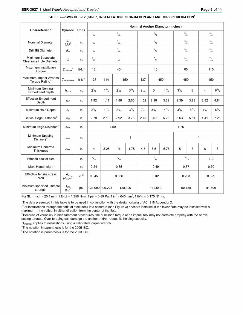
TABLE 2—KWIK HUS-EZ (KH-EZ) INSTALLATION INFORMATION AND ANCHOR SPECIFICATION1
Characteristic Symbol Units Nominal Anchor Diameter (inches)
For SI: 1 inch = 25.4 mm, 1 ft-lbf = 1.356 N-m, 1 psi = 6.89 Pa, 1 in2 = 645 mm2, 1 lb/in = 0.175 N/mm.
1The data presented in this table is to be used in conjunction with the design criteria of ACI 318 Appendix D. 2For installations through the soffit of steel deck into concrete (see Figure 3) anchors installed in the lower flute may be installed with a maximum 1 inch offset in either direction from the center of the flute. 3 Because of variability in measurement procedures, the published torque of an impact tool may not correlate properly with the above setting torques. Over-torquing can damage the anchor and/or reduce its holding capacity. 4Tinst,max applies to installations using a calibrated torque wrench. 5The notation in parenthesis is for the 2006 IBC. 6The notation in parenthesis is for the 2003 IBC.
ESR-3027 | Most Widely Accepted and Trusted Page 7 of 11
For SI: 1 inch = 25.4 mm, 1 ft-lbf = 1.356 N-m, 1 psi = 6.89 Pa, 1 in2 = 645 mm2, 1 lb/in = 0.175 N/mm.
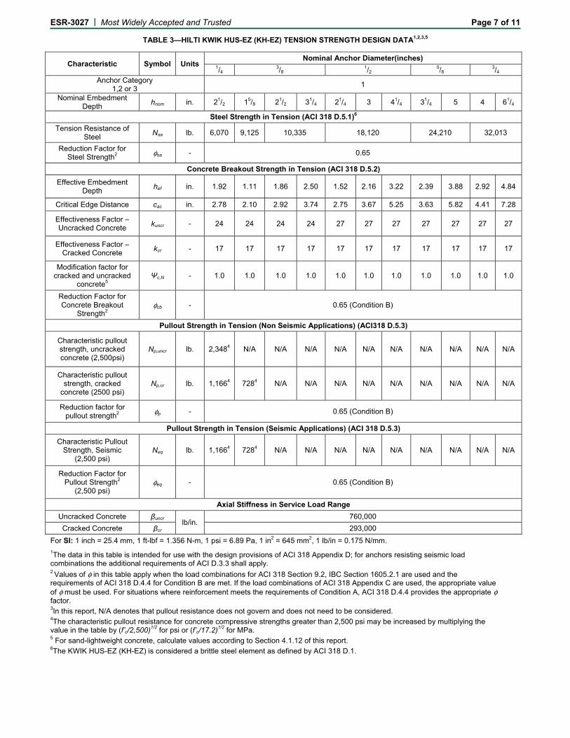
1The data in this table is intended for use with the design provisions of ACI 318 Appendix D; for anchors resisting seismic load combinations the additional requirements of ACI D.3.3 shall apply. 2 Values of φ in this table apply when the load combinations for ACI 318 Section 9.2, IBC Section 1605.2.1 are used and the requirements of ACI 318 D.4.4 for Condition B are met. If the load combinations of ACI 318 Appendix C are used, the appropriate value of φ must be used. For situations where reinforcement meets the requirements of Condition A, ACI 318 D.4.4 provides the appropriate φ factor. 3In this report, N/A denotes that pullout resistance does not govern and does not need to be considered. 4The characteristic pullout resistance for concrete compressive strengths greater than 2,500 psi may be increased by multiplying the value in the table by (f’c/2,500)1/2 for psi or (f’c/17.2)1/2 for MPa. 5 For sand-lightweight concrete, calculate values according to Section 4.1.12 of this report. 6The KWIK HUS-EZ (KH-EZ) is considered a brittle steel element as defined by ACI 318 D.1.
ESR-3027 | Most Widely Accepted and Trusted Page 8 of 11
For SI: 1 inch = 25.4 mm, 1 ft-lbf = 1.356 N-m, 1 psi = 6.89 Pa, 1 in2 = 645 mm2, 1 lb/in = 0.175 N/mm.
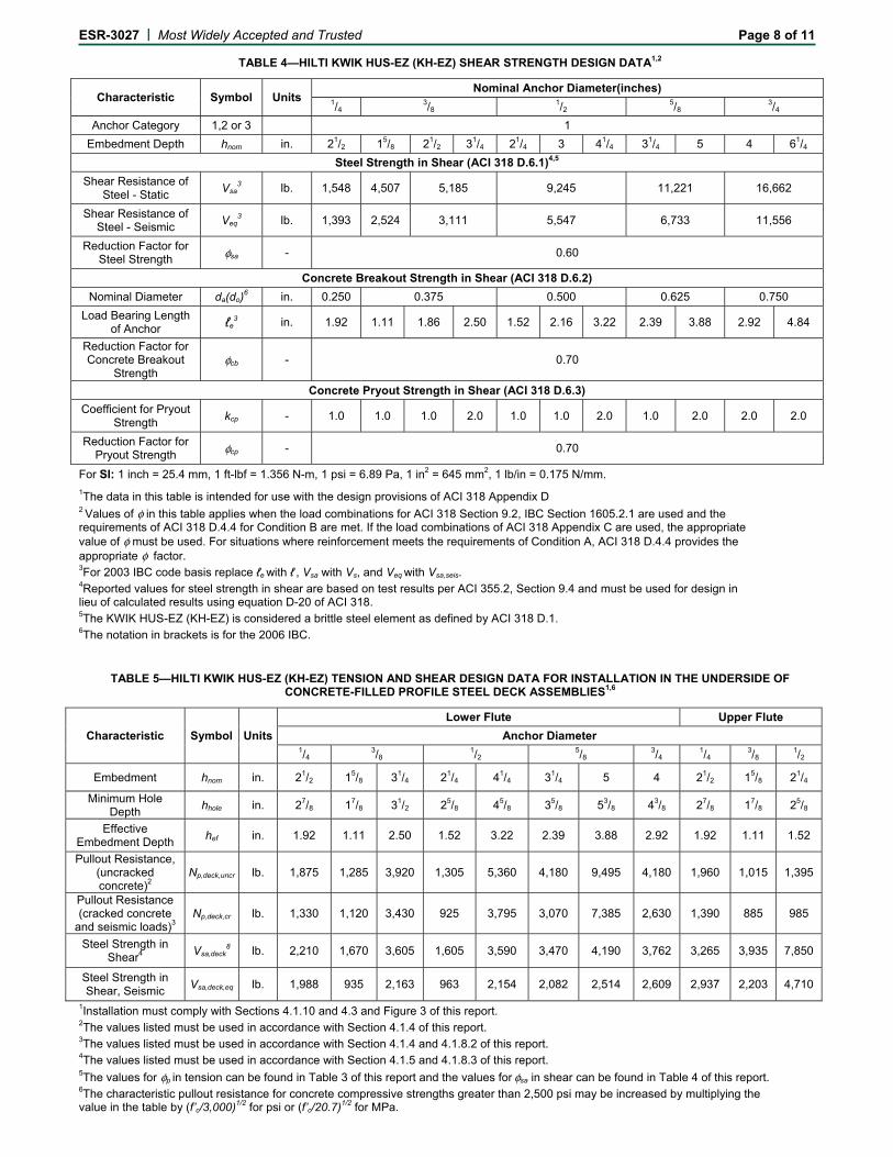
1The data in this table is intended for use with the design provisions of ACI 318 Appendix D 2 Values of φ in this table applies when the load combinations for ACI 318 Section 9.2, IBC Section 1605.2.1 are used and the requirements of ACI 318 D.4.4 for Condition B are met. If the load combinations of ACI 318 Appendix C are used, the appropriate value of φ must be used. For situations where reinforcement meets the requirements of Condition A, ACI 318 D.4.4 provides the appropriate φ factor. 3For 2003 IBC code basis replace ℓe with ℓ , Vsa with Vs, and Veq with Vsa,seis. 4Reported values for steel strength in shear are based on test results per ACI 355.2, Section 9.4 and must be used for design in lieu of calculated results using equation D-20 of ACI 318. 5The KWIK HUS-EZ (KH-EZ) is considered a brittle steel element as defined by ACI 318 D.1. 6The notation in brackets is for the 2006 IBC.
TABLE 5—HILTI KWIK HUS-EZ (KH-EZ) TENSION AND SHEAR DESIGN DATA FOR INSTALLATION IN THE UNDERSIDE OF CONCRETE-FILLED PROFILE STEEL DECK ASSEMBLIES1,6
1Installation must comply with Sections 4.1.10 and 4.3 and Figure 3 of this report. 2The values listed must be used in accordance with Section 4.1.4 of this report. 3The values listed must be used in accordance with Section 4.1.4 and 4.1.8.2 of this report. 4The values listed must be used in accordance with Section 4.1.5 and 4.1.8.3 of this report. 5The values for φp in tension can be found in Table 3 of this report and the values for φsa in shear can be found in Table 4 of this report. 6The characteristic pullout resistance for concrete compressive strengths greater than 2,500 psi may be increased by multiplying the value in the table by (f’c/3,000)1/2 for psi or (f’c/20.7)1/2 for MPa.
ESR-3027 | Most Widely Accepted and Trusted Page 9 of 11
FIGURE 3—INSTALLATION OF KWIK HUS-EZ (KH-EZ) IN SOFFIT OF CONCRETE
OVER STEEL DECK FLOOR AND ROOF ASSEMBLIES1
1Anchors may be placed in the upper or lower flute of the steel deck profile provided the minimum hole clearance is satisfied. Anchors in the lower flute may be installed with a maximum 1-inch offset in either direction from the center of the flute. The offset distance may be increased proportionally for profiles with lower flute widths greater than those shown provided the minimum lower flute edge distance is also satisfied.
1Single anchor with static tension load only. 2Concrete determined to remain uncracked for the life of the anchorage. 3Load combinations are taken from ACI 318 Section 9.2 (no seismic loading). 440% dead load and 60% live load, controlling load combination 1.2D + 1.6L. 5Calculation of weighted average for conversion factor α = 1.2(0.4) + 1.6(0.6) = 1.44. 6 f’c = 2,500 psi (normal weight concrete). 7 ca1 = ca2 ≥ cac. 8 h ≥ hmin. 9Values are for Condition B where supplementary reinforcement in accordance with ACI 318 D.4.4 is not provided.
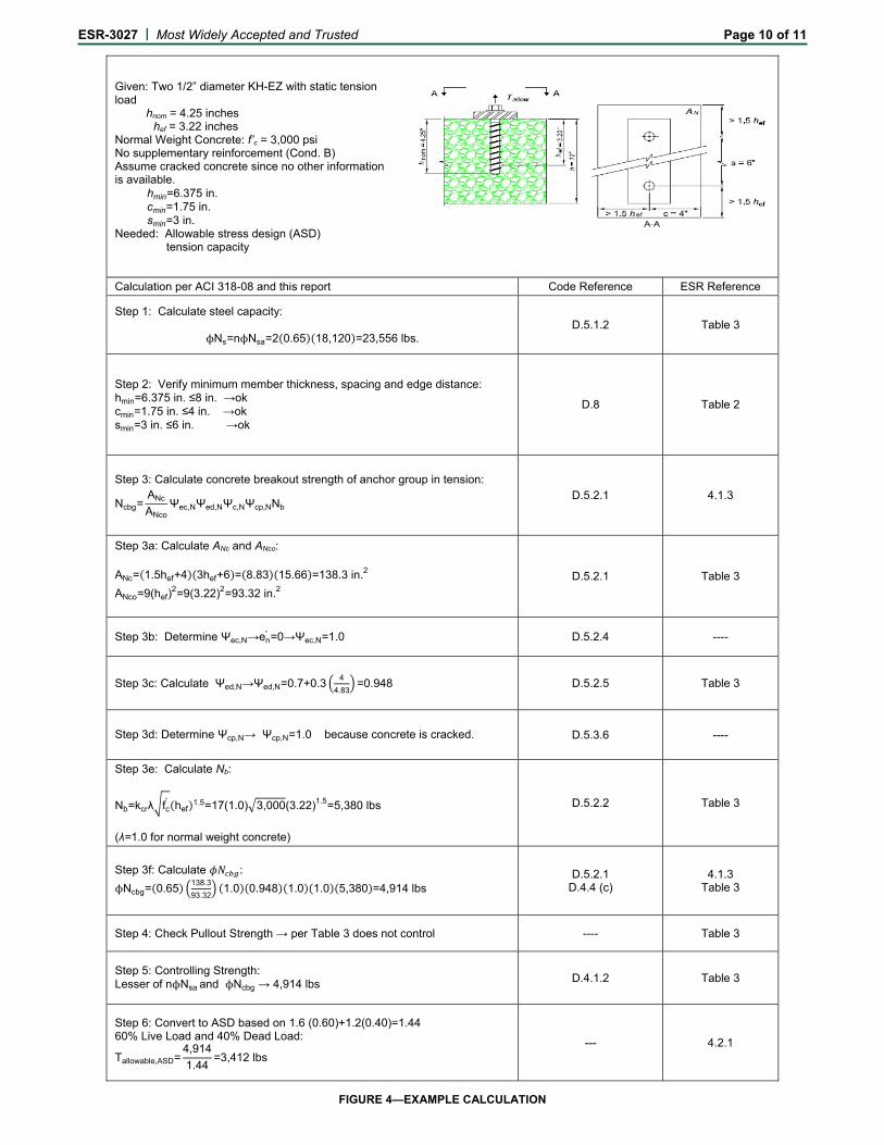
ESR-3027 | Most Widely Accepted and Trusted Page 10 of 11
Given: Two 1/2” diameter KH-EZ with static tension load hnom = 4.25 inches hef = 3.22 inches Normal Weight Concrete: f’c = 3,000 psi No supplementary reinforcement (Cond. B) Assume cracked concrete since no other information is available. hmin=6.375 in. cmin=1.75 in. smin=3 in. Needed: Allowable stress design (ASD) tension capacity
Calculation per ACI 318-08 and this report Code Reference ESR Reference