PRODUCTION OF HELICAL TWO STEP PIPE – USE OF MICROALLOYING ELEMENTS TO IMPROVE STRENGTH FOR GRADES UP TO X70 WITH SOUR SERVICE RESISTANCE Franz Martin Knoop Salzgitter Mannesmann Grossrohr GmbH Djordje Mirkovic, Volker Flaxa Djordje Mirkovic, Volker Flaxa Salzgitter Mannesmann Forschung GmbH
Transcript
PRODUCTION OF HELICAL TWO STEP PIPE – USE OF MICROALLOYINGELEMENTS TO IMPROVE STRENGTH FOR GRADES UP TO X70 WITH
SOUR SERVICE RESISTANCE
Franz Martin Knoop Salzgitter Mannesmann Grossrohr GmbH
• Development programme• Manufacturing issues relevant for sour service resistance
• steel production• steel production• hot rolling• pipe production
Dr. Knoop July 2013, London 2.
• Mechanical and corrosion test results• Summary and outlook
Introduction
Salzgitter's research and development activities for HSAW-pipe
• extending pipe/coil wall thickness up to 25.4 mm for grades X70 and X80• steel grades with high strength and excellent low temperature toughness
Salzgitter s research and development activities for HSAW pipe
• sour service resistant steel and pipe• enhancement of collapse resistance for shallow water off-shore applications• use of FEM for simulation of pipe forming and welding• use of FEM for simulation of pipe forming and welding• reducing residual stresses in pipe and weld seam• improving the strain capacity of pipes for strain based design requirements
Dr. Knoop July 2013, London 3.
• reduction of geometrical tolerances on steel and pipe
History
Failures of helical welded pipe p p
Dr. Knoop July 2013, London 4.
History
Cooking recipe for sour service material g p
Malcolm Gray „Full Scale Testing of Linepipe for Severe H2S Service“; NACE Canadian Regional Western Conference, A h Al k F b 19 22 1996Anchorage, Alaska, February 19—22. 1996
Dr. Knoop July 2013, London 5.
Development programme
Targeted pipe properties R&D and commercial projects
Quantity Grade / w th OD YS TS CVN DWTTHIC (base + weld) NACE
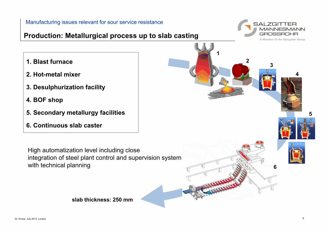
Production: Metallurgical process up to slab casting
Manufacturing issues relevant for sour service resistance
Production: Metallurgical process up to slab casting
12
31. Blast furnace 34
1. Blast furnace
2. Hot-metal mixer
3. Desulphurization facility
5
p y
4. BOF shop
5. Secondary metallurgy facilities y gy
6. Continuous slab caster
6
High automatization level including close integration of steel plant control and supervision systemwith technical planning 6
Dr. Knoop July 2013, London 8.
slab thickness: 250 mm
Steel plant: quality issues and measures
Manufacturing issues relevant for sour service resistance
Steel plant: quality issues and measures
Desired quality issues Consistently applied Salzgitter’s measures to attain them
Narrow steel composition tolerances
High steel cleanliness
• lowering non-metal inclusions
Continuous composition control and adjustment
Secondary metallurgy and appropriate casting procedure
ti i t ith ti l ti• lowering non-metal inclusions
( low [O] total)
• inclusion shape and size control
• gas stirring + caster with vertical section
• Ca – treatment for inclusion shape control
• vacuum degassing• low tramp element steel contents
( especially P and S )
• low H content
vacuum degassing
High slab centerline quality
• avoiding centerline segregation
Soft reduction at continuous slab caster
(C, Mn, P)
Dr. Knoop July 2013, London 9.
Steel cleanliness: non-metallic inclusions as HIC initiating sites
Manufacturing issues relevant for sour service resistance
Example: insufficient ladle rinsing and unsuitable degassing
Steel cleanliness: non-metallic inclusions as HIC initiating sites
top view of US scan
Rolling direction
top view of US scan
side view of US scan
HIC fracturesurface
Al
consistent application of LM refining measures to remove inclusionsfrom the steel melt, such as:
bottom stirring with N2 and Arf t h l lid t f i i i d l
Ouse of tap hole slide gates for minimized slag carry overoptimized Ca-treatment with Ca-wire injection; high Ca recoveryoptimized ladle rinsing procedureuse of argon shielded tundish for optimized flow pattern / inclusion removal
Dr. Knoop July 2013, London 10.
HIC cracks primarily initiated at Al-O inclusions and are traced back to slab upper half
use of argon shielded tundish for optimized flow pattern / inclusion removalapplication of caster with 2.6 m long vertical section instead of bow casters
Slab centerline quality: segregation effects
Manufacturing issues relevant for sour service resistance
Slab centerline quality: segregation effects
Example: casting without dynamic soft reduction
MartensiteHIC crack at strip mid thickness
top view of US scan
side view of US scan
consistent slab centerline quality optimization by application of Dynamic Soft Reductionconsistent slab centerline quality optimization by application of Dynamic Soft Reductiondynamic segment regulation (soft reduction), particularly at the point of final solidification
Dr. Knoop July 2013, London 11.
Production: layout of Salzgitter’s hot strip mill
Manufacturing issues relevant for sour service resistance
Production: layout of Salzgitter s hot strip mill
Reheating furnaces (4)
Slab sizingpressSlab sizingpress
R hi illR hi illDescaler
Roughing millRoughing mill
C hC h
Finishing train
Crop shearCrop shearRun-out table:Laminar cooling unit
descaler
Slab thickness = 250 mmSt i thi k 1 5 25Strip thickness = 1.5 - 25 mmStrip width = 900 - 2.000 mmStrip length = 100 - 2.000 m
3 Down coilers
Dr. Knoop July 2013, London 12.
One of the world’s most modern high performance hot strip mills
Hot strip mill: quality issues and measures
Manufacturing issues relevant for sour service resistance
Consistently applied Salzgitter’s measures to attain them
Hot strip mill: quality issues and measures
Desired quality issues
Continuous control and adjustment of rolling parameters
• highly planar
strip profile ness
µm]
Narrow strip dimension tolerances
• lowering of residual stresses in the
pipe bodies and welds strip profile
Stri
p th
ickn
vari
atio
n[µpipe bodies and welds
High strip surface quality
• prevention of surface defects e.g.
Thickness ± 60 µm
Precise temperature monitoring from furnace to coiler
Strip width [mm]slivers, roll-ins
Homogeneous strip temperature
distribution• highly desirable acicular ferrite microstructure along the
strip length and across the strip width
• Precise strip temperature prediction and control
distribution
• prevention of γ→α transformation
during the finishing p p p
based on run-out table simulation• strip microstructure adjustment
without undesirable phases
Dr. Knoop July 2013, London 13.
Hot strip mill: strip profile and temperature distribution
Manufacturing issues relevant for sour service resistance
Hot strip mill: strip profile and temperature distribution
Temperature scan after finishing train
Example: two-phase finish rolling / undesirable phases at strip edge area
Rolling direction
Temperature scan after finishing train
iatio
n
undercooled strip edges
Tem
p. d
ev
strongly elongated α-grains,Martensite also observed
precise temperature monitoring and control in every process phase and sectionto obtain fine-grain structure across the strip widthto obtain fine grain structure across the strip widthindispensable to prevent γ→α transformation already during the finishingto prevent undesirable phases, such as martensite
Rolling direction
Dr. Knoop July 2013, London 14.
properly cooled strip edgesNO HIC cracks observed !
Pipe production: Helical seam Two Step (HTS) technology
Manufacturing issues relevant for sour service resistance
Pipe production: Helical seam Two Step (HTS) technology
B = 1200 - 1500 mmα = 20 - 40°D = f (B, α) ( , α)D = 610 - 1676 mm
Second step: inside and outside
Fi i f i i h i k ldi
Second step: inside and outside submerged arc welding
Dr. Knoop July 2013, London 15.
First step: pipe forming with continuous tack welding
Pipe mill: quality issues and measures
Manufacturing issues relevant for sour service resistance
Consistently applied SZ’ measures to attain them
Pipe mill: quality issues and measures
Desired quality issues
Quality controls and R&D
• use of FEM simulation methods
• consistent quality controls and recording of forming
controlled cold working
• during coil straightening and pipe
forming consistent quality controls and recording of forming
parameters
• continuous control of pipe geometry using a patented in-situ
l di t t l
forming
• minimized springback
• optimized pre-bending of coil edges to
id ki d d i l l laser diameter control
• peaking below 0.8mm
avoid peaking and reducing local
stress which might affect sour gas
resistivity at weld area (SOHIC)
separating forming and welding by using the HTS –processno forming stresses during welding
Material selection and welding process controls
• qualification and careful selection of coil material and
welding consumables
maximum hardness of 248 HV
Dr. Knoop July 2013, London 16.
g
• continuous recording and documentation of all essential
welding parameters
Pipe mill: reduction of residual stresses
Manufacturing issues relevant for sour service resistance
Pipe mill: reduction of residual stresses
640
720
800
240
320
400
480
560
Stre
ss
, MPa
0°
0
80
160
240
0 2,5 5 7,5 10 12,5 15 17,5 20
Strain %
030°45°60°90°
Strain , %
2 0
2.5
3.0
[-]
Maximum value over wall thicknessInner surfaceOuter surface
Stress strain curves at different angles Simulation of different forming strategies
HIC: 1 set for both base material and weld per heat were tested. Result: mean CLR and CSR values of all samples 3.5 , 0.7 and 0.3 %, respectively
G d i ti it ! (d it f l ti l hi h C d M t t )
PipeDWTT [% shear area]; average of 2 specimens
0°C °C 10°C 20°C 40°C 60°C E ll l DWTT l
Good sour gas resistivity! (despite of relatively high C and Mn contents)
Dr. Knoop July 2013, London 20.
0°C -5°C -10°C -20°C -40°C -60°C
100 100 100 100 100 93100 100 100 100 95 83
Excellent low temperature DWTT results
SummarySummary and outlook
y
Large diameter helical line pipe for sour service up to X70 has been successfully d l d d d ddeveloped and produced
Critical parameters in steel production and hot rolling have been shown and their influence has been explained by means of examples.
Well balanced microalloying and steel cleanness has been achieved in industrial trials and commercial projects
All relevant process parameters during continuous casting and hot rolling wereAll relevant process parameters during continuous casting and hot rolling were effectively controlled and adjusted to the used chemistry an microalloying
All necessary measures for the improvement of HIC and SSC resistance have been optimized and managed during spiral pipe forming and weldingoptimized and managed during spiral pipe forming and welding
Excellent mechanical properties (incl. low temperature toughness) and corrosion resistance have been achieved
Dr. Knoop July 2013, London 21.
OutlookSummary and outlook
Next milestones are defined on basis of actual and future market needs
Growing interest for sour service resistant line pipe with heavy wall thickness up to 1’’ and grades up to X70 is expected
Technical solutions require further developmentq p
- on chemical composition of the base material,
- on welding consumables
- on further production parameters at each stage of production
- and on suitable equipment at each stage of production
Pi ith ll di t i th f 26’’ d hi h ll thi k (hi h ldPipes with smaller diameters in the range of 26’’ and higher wall thickness (high cold forming degree) need further development