UNIVERSIDADE DA BEIRA INTERIOR Ciências Production of membranes for filtration of biomolecules Pedro Henrique Barata Castilho Dissertação para obtenção do Grau de Mestre em Biotecnologia (2º ciclo de estudos) Orientador: Prof. Doutor António Miguel Parreira Cabral Forjaz Morão Co-orientador: Prof. Doutor Ilídio Joaquim Sobreira Correia Covilhã, Outubro de 2014
Transcript
UNIVERSIDADE DA BEIRA INTERIOR Ciências
Production of membranes for filtration of
biomolecules
Pedro Henrique Barata Castilho
Dissertação para obtenção do Grau de Mestre em
Biotecnologia (2º ciclo de estudos)
Orientador: Prof. Doutor António Miguel Parreira Cabral Forjaz Morão Co-orientador: Prof. Doutor Ilídio Joaquim Sobreira Correia
Covilhã, Outubro de 2014
UNIVERSIDADE DA BEIRA INTERIOR Ciências
Produção de membranas para filtração de
biomoléculas
Pedro Henrique Barata Castilho
Dissertação para obtenção do Grau de Mestre em
Biotecnologia (2º ciclo de estudos)
Orientador: Prof. Doutor António Miguel Parreira Cabral Forjaz Morão Co-orientador: Prof. Doutor Ilídio Joaquim Sobreira Correia
Covilhã, Outubro de 2014
iii
iv
List of Publications
Article published in peer reviewed international scientific journal:
Figure 2 Pressure-driven membrane process spectrum (adapted from [37]).
Chapter I: Introduction
9
Figure 3 Membrane process characteristics: microfiltration, ultrafiltration, nanofiltration and RO distinguished (adapted from [38]).
1.2.2 Membranes applications
Membrane technology can be used in a large number of applications such as solid-liquid
separation, concentration, buffer exchange, purification and sterilization [25, 27, 39].
Membrane technology not only has been extensively used for several applications in
downstream processes, but in upstream processes too, which leads to a demanding role in the
purification of biotechnology products [19, 29]. Furthermore, membrane processes are also
used for water purification [27, 37], nucleic acids (pDNA and RNA) recovery and purification
[15, 20] and gas–liquid contacting and emulsification [24]. In Table 2 are presented some
commercial available membranes, as well as their composition and applications.
Chapter I: Introduction
10
Table 2 Applications of the commercially available membranes used in membrane processes ([29, 32, 37, 39]).
Commercially available
membranes
Materials used to produce
membranes Applications
MF
Nylaflo (Pall
Corporation)
GVWP (Millipore)
MCE (Advantec Toyo
Corp.)
Cellulose acetate
Drinking water treatment
Clarification
Sterile filtration
Poly(vinylidene fluoride)
Polyamides
Polyolefins
Nylon
Poly(tetrafluoroethylene)
UF
FSM0.45PP (Alfa Laval)
3038, 3065 and 3028
(IRIS)
ES625 (PCI Membrane
Systems)
Polyacrylonitrile copolymers
Aromatic polyamides
Polysulfone
Poly(vinylidene fluoride)
Concentration
Buffer exchange
Desalination
Sterile Filtration
Biomolecule recuperation
Clarification
NF
MPS-44 (Koch
Membrane) Aromatic polyamides
Cellulose acetate
Desalination
NTR7250 (Nitto-Denko) Salt separation
NF55 (Dow) Waste water treatment
RO
ES20 (Nitto-Denko) Cellulose acetate
Polyamide
Ultrapure water production
UTC-70 (Toray) Desalination
NCM1 (Hydranautics) Waste water treatment
Chapter I: Introduction
11
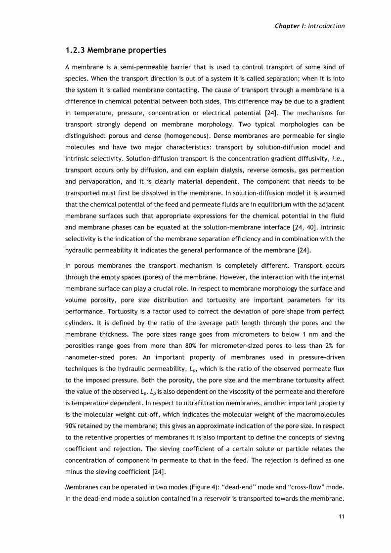
1.2.3 Membrane properties
A membrane is a semi-permeable barrier that is used to control transport of some kind of
species. When the transport direction is out of a system it is called separation; when it is into
the system it is called membrane contacting. The cause of transport through a membrane is a
difference in chemical potential between both sides. This difference may be due to a gradient
in temperature, pressure, concentration or electrical potential [24]. The mechanisms for
transport strongly depend on membrane morphology. Two typical morphologies can be
distinguished: porous and dense (homogeneous). Dense membranes are permeable for single
molecules and have two major characteristics: transport by solution-diffusion model and
intrinsic selectivity. Solution-diffusion transport is the concentration gradient diffusivity, i.e.,
transport occurs only by diffusion, and can explain dialysis, reverse osmosis, gas permeation
and pervaporation, and it is clearly material dependent. The component that needs to be
transported must first be dissolved in the membrane. In solution-diffusion model it is assumed
that the chemical potential of the feed and permeate fluids are in equilibrium with the adjacent
membrane surfaces such that appropriate expressions for the chemical potential in the fluid
and membrane phases can be equated at the solution-membrane interface [24, 40]. Intrinsic
selectivity is the indication of the membrane separation efficiency and in combination with the
hydraulic permeability it indicates the general performance of the membrane [24].
In porous membranes the transport mechanism is completely different. Transport occurs
through the empty spaces (pores) of the membrane. However, the interaction with the internal
membrane surface can play a crucial role. In respect to membrane morphology the surface and
volume porosity, pore size distribution and tortuosity are important parameters for its
performance. Tortuosity is a factor used to correct the deviation of pore shape from perfect
cylinders. It is defined by the ratio of the average path length through the pores and the
membrane thickness. The pore sizes range goes from micrometers to below 1 nm and the
porosities range goes from more than 80% for micrometer-sized pores to less than 2% for
nanometer-sized pores. An important property of membranes used in pressure-driven
techniques is the hydraulic permeability, Lp, which is the ratio of the observed permeate flux
to the imposed pressure. Both the porosity, the pore size and the membrane tortuosity affect
the value of the observed Lp. Lp is also dependent on the viscosity of the permeate and therefore
is temperature dependent. In respect to ultrafiltration membranes, another important property
is the molecular weight cut-off, which indicates the molecular weight of the macromolecules
90% retained by the membrane; this gives an approximate indication of the pore size. In respect
to the retentive properties of membranes it is also important to define the concepts of sieving
coefficient and rejection. The sieving coefficient of a certain solute or particle relates the
concentration of component in permeate to that in the feed. The rejection is defined as one
minus the sieving coefficient [24].
Membranes can be operated in two modes (Figure 4): “dead-end” mode and “cross-flow” mode.
In the dead-end mode a solution contained in a reservoir is transported towards the membrane.
Chapter I: Introduction
12
The components rejected by the membrane will accumulate at the membrane surface and
eventually will diffuse back to the bulk of the solution in the reservoir. On the other hand, in
cross-flow mode, the feed flows parallel to the membrane surface. In both cases the stream
that passes through membrane is called “permeate”, while the remainder is defined as
“retentate”. Therefore, in a cross-flow system the permeate stream flows perpendicular to the
feed stream but in a dead-end system the permeate flows in the direction of the feed [24].
Figure 4 Comparison between a (a) dead-ended filtration and a (b) cross-flow filtration (adapted from [29]).
1.2.4 Factors that affect the filtration process
In the filtration process, there are certain factors that affect the filtration, these factors are,
mainly membrane selectivity, the flux and the system capacity [27].
The selectivity of the membrane is determined by the pore size distribution and the membrane
surface properties, i.e., highly selective ultrafiltration membranes can be developed using
electrically charged membranes that have very high retention of macromolecules with the same
polarity and similarly. By turn, adsorptive membranes can provide highly selective separations
based on the specific binding of several components on the surface of the membrane [41, 42].
The selectivity is directly related to the solute filtering coefficient:
Chapter I: Introduction
13
𝑆 =𝐶𝑓
𝐶𝐹
where Cf is permeate solution and CF is the feed solution [27].
The flux is evaluated using the actual feedstock of interest, being typically less than the value
predicted from the clean membrane permeability, due to fouling and concentration
polarization effects [43]. The pure water flux is related to the membrane hydraulic
permeability:
𝐿𝑝 =𝐽𝑣𝛥𝑃
where Jv is the flux (volumetric flow rate per unit membrane area) and ΔP is the transmembrane
pressure difference [27]. The membrane fouling can arise from adsorption on and within the
membrane pores and/or from the formation of a deposit on the external surface of the
membrane (Figure 5). Concentration polarization refers to the accumulation of completely or
partially retained solutes at the upstream surface of the membrane due to bulk mass transfer
limitations of the membrane. The dominant effect in protein ultrafiltration is the reduction in
the effective pressure driving force due to osmotic pressure effects [27]. The extent of the
concentration polarization can be controlled by adjusting the fluid flow characteristics,
typically by providing high local shear rates in cross-flow filtration modules or by stirring the
feed in “dead-end” filtration [44, 45].
Figure 5 Membrane fouling can occur due to adsorption within the membrane pores (a), adsorption on the membrane surface (b) or by both of them (c) (adapted from [46]).
The system capacity is defined as the volume of feed that can be processed per unit membrane
area, before the membrane needs to be regenerated or replaced. For membrane processes
(1)
(2)
Chapter I: Introduction
14
operated at a constant transmembrane pressure, the capacity is typically defined as the point
at which the filtrate flow rate has dropped to less than 10% of its initial value or below a pre-
determined flux that is required for a particular application. For operation at constant filtrate
flux, the capacity is defined by the maximum pressure drop that can be tolerated by the system,
and can be limited by the membrane. The adsorptive membrane capacity is defined by the
appearance of an unacceptable level of a key component in the flow-through stream (referred
to as breakthrough). Breakthrough is determined by both the equilibrium (static) binding
properties of the membrane in combination with any mass transfer limitations in the device.
The capacity of depth filters can be determined by either the breakthrough of a key component
or by an unacceptable pressure drop [27].
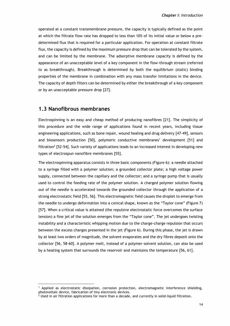
1.3 Nanofibrous membranes
Electrospinning is an easy and cheap method of producing nanofibres [21]. The simplicity of
this procedure and the wide range of applications found in recent years, including tissue
engineering applications, such as bone repair, wound healing and drug delivery [47-49], sensors
and biosensors production [50], polymeric conductive membranes1 development [51] and
filtration2 [52-54]. Such variety of applications leads to an increased interest in developing new
types of electrospun nanofibre membranes [55].
The electrospinning apparatus consists in three basic components (Figure 6): a needle attached
to a syringe filled with a polymer solution; a grounded collector plate; a high voltage power
supply, connected between the capillary and the collector; and a syringe pump that is usually
used to control the feeding rate of the polymer solution. A charged polymer solution flowing
out of the needle is accelerated towards the grounded collector through the application of a
strong electrostatic field [55, 56]. This electromagnetic field causes the droplet to emerge from
the needle to undergo deformation into a conical shape, known as the “Taylor cone” (Figure 7)
[57]. When a critical value is attained (the repulsive electrostatic force overcomes the surface
tension) a fine jet of the solution emerges from the “Taylor cone”. The jet undergoes twisting
instability and a characteristic whipping motion due to the charge-charge repulsion that occurs
between the excess charges presented in the jet (Figure 6). During this phase, the jet is drawn
by at least two orders of magnitude, the solvent evaporates and the dry fibres deposit onto the
collector [56, 58-60]. A polymer melt, instead of a polymer-solvent solution, can also be used
by a heating system that surrounds the reservoir and maintains the temperature [56, 61].
1 Applied as electrostatic dissipation, corrosion protection, electromagnetic interference shielding, photovoltaic device, fabrication of tiny electronic devices. 2 Used in air filtration applications for more than a decade, and currently in solid-liquid filtration.
Chapter I: Introduction
15
Figure 6 Representation of the electrospinning apparatus (adapted from [56]).
Figure 7 Image representing the Taylor cone (adapted from [56]).
1.3.1 Parameters that influence the production of nanofibrous
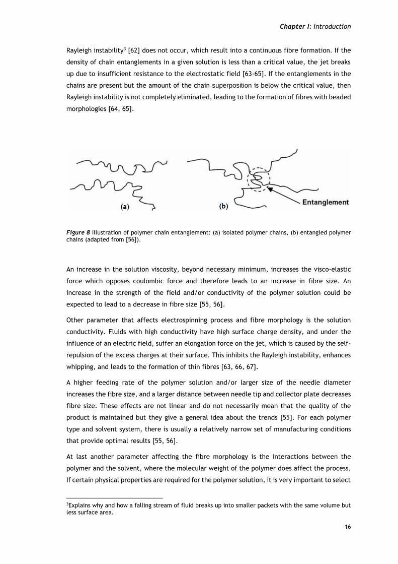
The fibre structure is affected by different factors such as the density of chain entanglements,
Figure 19 ATR-FTIR spectra of agarose powder (a), Nylaflo membrane (b) and modified-Nylaflo membrane (c).
The amount of chemical elements at the surface of the PCL ENM and PCL ENM coated
membranes (Figure 20) shows that the surface coating of the PCL ENM was achieved due to the
increase of the amount of oxygen atoms (characteristic of polyethylene oxid), and the
appearance of the sulphur peak (belonging to the negative group of sulphate present in the
molecule of k-carrageenan) (Table 4)
Figure 20 EDS spectra of PCL ENM membrane (a) and PCL ENM coated (b).
Chapter III: Results and discussion
39
Table 4 EDS analysis of the membranes.
Samples C (at %) O (at %) S (at %)
PCL ENM 74.15 25.85 -
PCL ENM coated 62.27 37.61 0.12-
Figure 21 shows the amount of chemical elements at the surface of the unmodified/modified-
Nylaflo membrane. Herein, it can be concluded that the surface modification was achieved,
once the percentage of oxygen elements (characteristic from agarose) was higher for the
modified membrane (table 5).
Figure 21 EDS spectra of Nylaflo membrane (a) and modified-Nylaflo membrane (b).
Table 5 EDS analysis of the membranes.
Samples C (at %) O (at %) N (at %)
Nylaflo 72.06 14.18 13.75
Modified-Nylaflo 57.41 42.59 -
Chapter III: Results and discussion
40
3.1.3 Surface properties characterization
Contact angles were determined to evaluate the hydrophobic character of each membrane.
This is an important property when considering the filtration of solutions with biomolecules, in
fact, it is well-known that hydrophilic membranes generally perform better than hydrophobic,
due to the adsorption phenomena of the biomolecules in to the surface of the membrane [131].
As can be seen in Table 6 the uncoated PCL membrane presented a higher contact angle
(118.72º), which is indicative of a hydrophobic character. After applying the coat (PEO+k-
carrageenan) the contact angle decreased to 99.43º, indicating that the membrane became
more hydrophilic. The Nylaflo membrane showed to be the most hydrophilic, presenting a
contact angle of 28.03º for the modified-Nylaflo an increase on the contact angle was observed,
however the hydrophilic character of the membrane was essentially kept, which is important
to prevent the occurrence of fouling phenomena during the purification process, namely due
to protein adsorption.
Table 6 Contact angles of the membranes.
Membranes Water contact angle
PCL ENM 118.72º ± 0.73º
PCL ENMC 99.43º ± 0.20º
Nylaflo 28.03º ± 5.40º
Modified-Nylaflo 32.68 ± 8.13º
Chapter III: Results and discussion
41
3.2 Membrane filtration studies
3.2.1 Hydraulic permeability
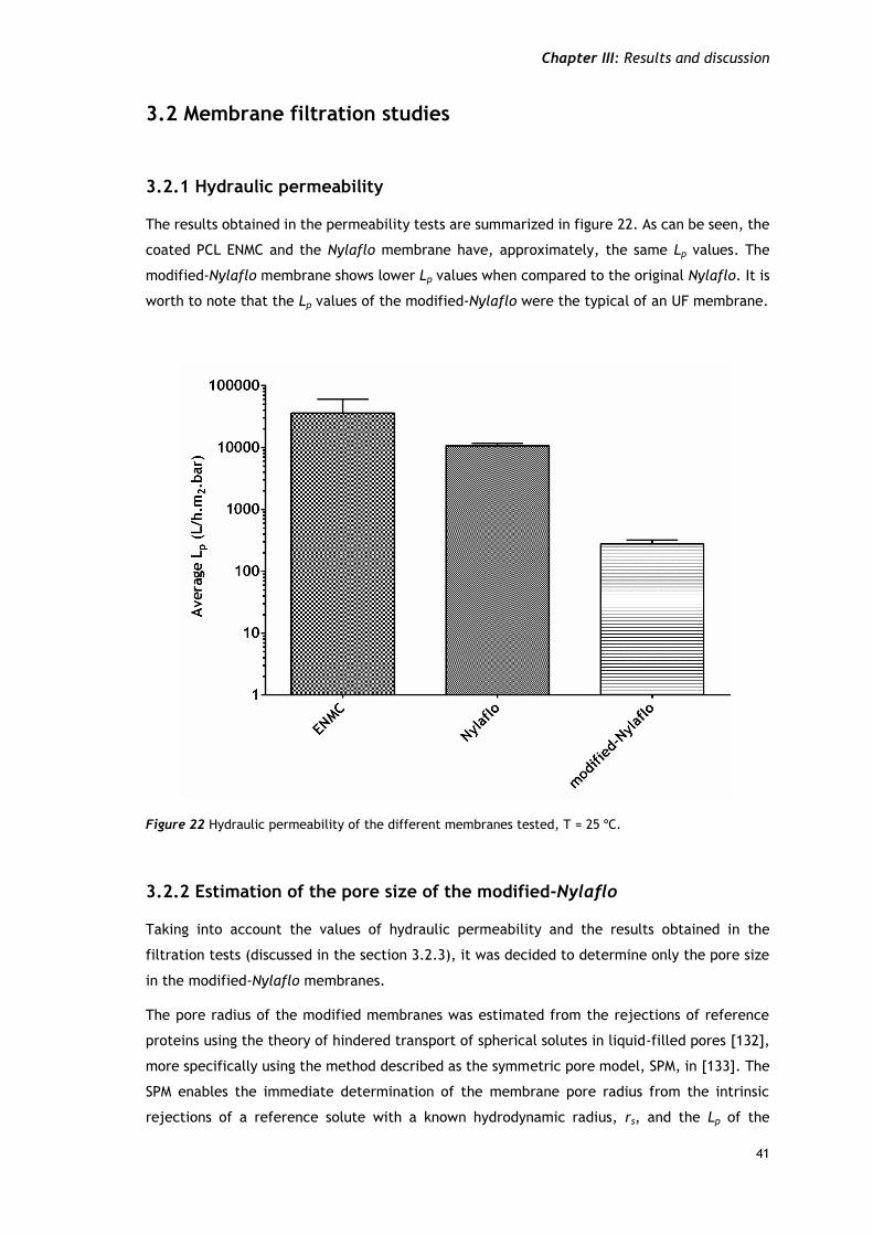
The results obtained in the permeability tests are summarized in figure 22. As can be seen, the
coated PCL ENMC and the Nylaflo membrane have, approximately, the same Lp values. The
modified-Nylaflo membrane shows lower Lp values when compared to the original Nylaflo. It is
worth to note that the Lp values of the modified-Nylaflo were the typical of an UF membrane.
Figure 22 Hydraulic permeability of the different membranes tested, T = 25 ºC.
3.2.2 Estimation of the pore size of the modified-Nylaflo
Taking into account the values of hydraulic permeability and the results obtained in the
filtration tests (discussed in the section 3.2.3), it was decided to determine only the pore size
in the modified-Nylaflo membranes.
The pore radius of the modified membranes was estimated from the rejections of reference
proteins using the theory of hindered transport of spherical solutes in liquid-filled pores [132],
more specifically using the method described as the symmetric pore model, SPM, in [133]. The
SPM enables the immediate determination of the membrane pore radius from the intrinsic
rejections of a reference solute with a known hydrodynamic radius, rs, and the Lp of the
Chapter III: Results and discussion
42
membrane [133]. Intrinsic rejections were calculated from the observed rejections, by
estimating the mass transfer coefficient of the proteins in the concentration polarization layer,
using the correlation proposed by Opong & Zydney [134]. The proteins used in this work and
their relevant properties are summarized in Table 7. The observed rejections and the
corresponding estimate values of pore radius are indicated in Table 8. The hydraulic
permeability of the membranes was measured before and after filtration to confirm the
absence of fouling in these tests. The average pore radius obtained was 33 nm, which is
substantially lower than the nominal value of the pore radius of the Nylaflo commercial
membrane, which is 100 nm.
Table 7 Selected properties of the proteins tested.
Protein Mw (kDa) rs (m) Ds (m2/s) Ref
BSA 67 3.55×10⁻⁹ 6.95×10⁻¹¹ [135, 136]
γ-globulins 158 5.59×10⁻⁹ 4.42×10⁻¹¹ [135, 136]
Table 8 Observed rejections of BSA and γ-globulins at 760 rpm, 25 ºC at the indicated values of transmembrane pressure. Protein concentrations: 0.3 g/L.
Protein P (bar) Jv (L/h.m2) Robs Rm rp (nm)
BSA 0.05 5.3 0.046 0.057 34
0.10 10 0.054 0.080 28
γ-globulins 0.10 9.8 0.072 0.12 36
3.2.3 Plasmid DNA experiments
Biomolecules separation is important in biology, medicine and chemistry [39, 137]. Herein,
pDNA a flexible biomolecule was used in this study. After membrane characterization, the
quantification of pDNA rejection was carried out (figure 23 and 24).
As can be seen in Figure 23, when the electrospun membrane (filtration with constant flux) was
used, the rejection4 (Robs) has a tendency to decrease with the increase of the flux (Jv), which
is indicative of the occurrence of significant concentration polarization. However, the most
4 The rejection (Robs) is defined as 1-Cp/Cb, where Cp is the concentration of the solute (pDNA in this case)
in the permeate and Cb is the concentration in the bulk of the feeding solution.
Chapter III: Results and discussion
43
important fact to highlight about these results was the occurrence of pDNA rejection itself,
taking into account the very open structure of the produced membranes.
For the modified-Nylaflo membrane (filtration with constant pressure), at low fluxes of
permeate the membrane presented near 100% of pDNA rejection, which makes it adequated
for application in pDNA purification (one cannot say the same about the PCL ENMC membrane).
Also, it was again observed that when the flux was increased, the rejection was decreased.
Knowing the rp value of the modified-Nylaflo and the radius of gyration, rg, of the pDNA
molecule, Morão et al. [138] had recently shown that one can be accurately estimate through
the observed rejections of this type of flexible biomolecules, in the case of several conventional
(asymmetric polymeric) ultrafiltration membranes [20, 23, 138]. The model used for the
calculations assumes the occurrence of flow induced molecular deformation of the molecular
structure of the macromolecules, which leads to their permeation through narrow pores, as a
consequence of the permeation flux. The probability of permeation, thus the intrinsic filtering
coefficient, can be estimated from the ratio rg/rp. In order to estimate observed sieving
coefficients it was necessary, also, to estimate the concentration polarization of the
macromolecule and for this purpose could be used the correlation obtained by Opong & Zydney
[134] as described by Morão et al. [138]. Using this model, the theoretical curve (shown in
Figure 24) was calculated using rg = 90 nm; the rg value depends on the ionic strength of the
solution and it was estimated following the method proposed by Morão et al. [138]. The
observed rejections appeared to be significantly higher than what was predicted, strongly
suggesting that the structure of the hydrogel layer (agarose) affected the retention of pDNA
molecules, by significantly increasing it. A possible explanation for this phenomena may be
that, although the porosity of the modified-Nylaflo membranes decreased in respect to the
non-modified membrane. The experimental values obtained were still very high, in fact, near
30% of porosity is a very high value for the membrane porosity of an ultrafiltration membrane,
considering that conventional ultrafiltration membranes have typical porosities in the range of
2-7% [135, 139]. The effect of the porosity at the membrane surface, which can be identified
with the ratio of the pore area to the membrane area, on the rejection of a large flexible
molecule like pDNA can be significant, considering that flow-induced deformation is expected
to decrease as the porosity increases, due to less suction effects. A similar effect may also
explain the unexpectedly high pDNA rejections observed for the PCL ENMS membranes, taking
into account the high porosity of these membranes.
Chapter III: Results and discussion
44
Figure 23 Observed rejections of plasmid pVax1-LacZ by the PCL ENMC membrane.
Figure 24 Predicted and observed rejections of plasmid pVAX1-LacZ by the modified-Nylaflo membrane.
Conclusion & Future Perspectives
Chapter IV
Chapter IV: Conclusion and future perspectives
46
4. Conclusion and future perspectives
In this work two different membranes were produced, an electrospun nanofibre membrane and
a modified nylon. The electrospun membrane was produced, by the deposition of a PEO/k-
carrageenan layer on a PCL support. Both layers (PEO/k-carrageenan and PCL) were produced
by electrospinning. Electrospun nanofibres that have been previously used in a practical and
cost-effective way for the production of polymer scaffolds and also for microfiltration
applications were found to be not suitable, however, for pDNA purification since the obtained
rejections are not high enough.
The modified-Nylaflo membrane presented characteristics of an ultrafiltration membrane,
namely in terms of hydraulic permeability and pore size, however with a very high porosity
when compared to conventional asymmetric polymeric ultrafiltration membranes. The modified
membrane presented 100% of pDNA rejection at low values of flux. Accordingly, these
membranes can be used to purify pDNA. This fact and also the simplicity of the modification
procedure makes this type of modified membranes potential candidates for being used in
practical applications for in pDNA purification.
In future, through the optimization of the electrospinning process of k-carrageenan or using
other negatively charged polymers, it is possible that UF membranes can be also produced
taking into account the importance of the electrical charge of the membrane for pDNA
rejection.
Despite the potential shown by modified-Nylaflo membranes there were some issues that need
to be addressed before considering this work for industrial purposes. The most relevant one is
the production process feasibility in large scale which needs to be investigated. Furthermore,
pDNA recovery with simultaneous removal of the different contaminants (presented in the
process stream before UF) namely RNA removal, needs to be investigated by testing membranes
prepared with different agarose concentrations and possibly other hydrogels.
Bibliography
Chapter V
Chapter V: Bibliography
48
5. Bibliography
1. Schleef, M., Plasmids for therapy and vaccination. 2008: John Wiley & Sons.
2. Horn, N.A., et al., Cancer gene therapy using plasmid DNA: purification of DNA for
human clinical trials. Human Gene Therapy, 1995. 6(5): p. 565-573.
3. Liu, F., Y. Song, and D. Liu, Hydrodynamics-based transfection in animals by systemic
administration of plasmid DNA. Gene Ther, 1999. 6(7): p. 1258-1266.
4. McConkey, S.J., et al., Enhanced T-cell immunogenicity of plasmid DNA vaccines
boosted by recombinant modified vaccinia virus Ankara in humans. Nature medicine,
2003. 9(6): p. 729-735.
5. Tang, D.-c., M. DeVit, and S.A. Johnston, Genetic immunization is a simple method for
eliciting an immune response. Nature, 1992. 356(6365): p. 152-154.
6. Prather, K.J., et al., Industrial scale production of plasmid DNA for vaccine and gene
therapy: plasmid design, production, and purification. Enzyme and microbial
technology, 2003. 33(7): p. 865-883.
7. Donnelly, J.J., B. Wahren, and M.A. Liu, DNA vaccines: progress and challenges. The
Journal of Immunology, 2005. 175(2): p. 633-639.
8. Ghanem, A., R. Healey, and F.G. Adly, Current trends in separation of plasmid DNA
vaccines: A review. Analytica chimica acta, 2013. 760: p. 1-15.
9. Wirth, T., N. Parker, and S. Ylä-Herttuala, History of gene therapy. Gene, 2013.
525(2): p. 162-169.
10. Mountain, A., Gene therapy: the first decade. Trends in biotechnology, 2000. 18(3): p.
119-128.
11. Emery, D.W., Gene therapy for genetic diseases: On the horizon. Clinical and Applied
Immunology Reviews, 2004. 4(6): p. 411-422.
12. Liu, M., DNA vaccines: a review. Journal of internal medicine, 2003. 253(4): p. 402-
410.
13. Kutzler, M.A. and D.B. Weiner, DNA vaccines: ready for prime time? Nature Reviews
Genetics, 2008. 9(10): p. 776-788.
14. Liu, M.A., DNA vaccines: an historical perspective and view to the future.
Immunological reviews, 2011. 239(1): p. 62-84.
15. Kahn, D.W., et al., Purification of plasmid DNA by tangential flow filtration.
Biotechnology and bioengineering, 2000. 69(1): p. 101-106.
Chapter V: Bibliography
49
16. Eon-Duval, A., et al., Removal of RNA impurities by tangential flow filtration in an
RNase-free plasmid DNA purification process. Analytical biochemistry, 2003. 316(1):
p. 66-73.
17. Sousa, F., et al., Selective purification of supercoiled plasmid DNA from clarified cell
lysates with a single histidine–agarose chromatography step. Biotechnology and
applied biochemistry, 2006. 45(3): p. 131-140.
18. Sousa, F. and J. Queiroz, Supercoiled plasmid quality assessment by analytical
arginine-affinity chromatography. Journal of Chromatography A, 2011. 1218(1): p.
124-129.
19. Prazeres, D. and G. Ferreira, Design of flowsheets for the recovery and purification of
plasmids for gene therapy and DNA vaccination. Chemical Engineering and Processing:
Process Intensification, 2004. 43(5): p. 609-624.
20. Nunes, J.C., et al., Plasmid DNA recovery from fermentation broths by a combined
process of micro-and ultrafiltration: modeling and application. Journal of Membrane
Science, 2012. 415-416: p. 24-35.
21. Correia, T.R., et al., A bi-layer electrospun nanofiber membrane for plasmid DNA
recovery from fermentation broths. Separation and Purification Technology, 2013.
112: p. 20-25.
22. Sun, B., et al., Large-scale purification of pharmaceutical-grade plasmid DNA using
tangential flow filtration and multi-step chromatography. Journal of bioscience and
bioengineering, 2013. 116(3): p. 281-286.
23. Nunes, J.C., et al., Plasmid DNA/RNA separation by ultrafiltration: Modeling and
application study. Journal of Membrane Science, 2014. 463: p. 1-10.
24. De Jong, J., R. Lammertink, and M. Wessling, Membranes and microfluidics: a review.
Lab on a Chip, 2006. 6(9): p. 1125-1139.
25. Rathore, A. and A. Shirke, Recent developments in membrane-based separations in
biotechnology processes: review. Preparative Biochemistry and Biotechnology, 2011.
41(4): p. 398-421.
26. Plumb, K., Continuous processing in the pharmaceutical industry: changing the mind
set. Chemical Engineering Research and Design, 2005. 83(6): p. 730-738.
27. van Reis, R. and A. Zydney, Bioprocess membrane technology. Journal of Membrane
Science, 2007. 297(1): p. 16-50.
28. Freitas, S., et al., Alternatives for the intermediate recovery of plasmid DNA:
performance, economic viability and environmental impact. Biotechnology journal,
2009. 4(2): p. 265-278.
Chapter V: Bibliography
50
29. Charcosset, C., Membrane processes in biotechnology: an overview. Biotechnology
advances, 2006. 24(5): p. 482-492.
30. Hughes, R., Industrial membrane separation technology. 1996: Springer.
31. Van der Bruggen, B., et al., A review of pressure‐driven membrane processes in
wastewater treatment and drinking water production. Environmental progress, 2003.
22(1): p. 46-56.
32. Baker, R.W., Membrane technology and applications. 3rd ed. 2012: John Wiley & Sons.
33. Mulder, M., Basic principles of membrane technology. 2nd ed. 1996: Kluwer Academic
Pub.
34. Clever, M., et al., Process water production from river water by ultrafiltration and
reverse osmosis. Desalination, 2000. 131(1): p. 325-336.
35. Edzwald, J.K., Water quality & treatment: a handbook on drinking water. 6th ed. 2011:
AWWA and McGraw-Hill Inc.
36. Ferreira Filho, S.S., Water treatment: principles and design. 2nd ed. 2005: Montgomery
Watson Harsa.
37. Membrane Filtration. 1999, National Drinking Water ClearingHouse.
38. Zena-membranes. Membrane process characteristic. 2014 [cited 2014 15-08-2014];
Available from: http://www.zena-membranes.cz/index.php/news.
39. Van Reis, R. and A. Zydney, Membrane separations in biotechnology. Current Opinion
in Biotechnology, 2001. 12(2): p. 208-211.
40. Wijmans, J. and R. Baker, The solution-diffusion model: a review. Journal of
membrane science, 1995. 107(1): p. 1-21.
41. Van Reis, R., et al., High-performance tangential flow filtration using charged
membranes. Journal of Membrane Science, 1999. 159(1): p. 133-142.
42. Mehta, A. and A.L. Zydney, Effect of membrane charge on flow and protein transport
during ultrafiltration. Biotechnology progress, 2006. 22(2): p. 484-492.
43. Zeman, L.J. and A.L. Zydney, Microfiltration and ultrafiltration: principles and
applications. 1996: M. Dekker.
44. Hallström, B. and M. Lopez-Leiva, Description of a rotating ultrafiltration module.
Desalination, 1977. 24(1): p. 273-279.
45. Chung, K.Y., R. Bates, and G. Belfort, Dean vortices with wall flux in a curved channel
membrane system. IV: Effect of vortices on permeation fluxes of suspensions in
microporous membrane. Journal of membrane science, 1993. 81(1-2): p. 139-150.
Chapter V: Bibliography
51
46. Ni, B.-J., B.E. Rittmann, and H.-Q. Yu, Soluble microbial products and their
implications in mixed culture biotechnology. Trends in biotechnology, 2011. 29(9): p.
454-463.
47. Yang, Y., et al., Electrospun fibers with plasmid bFGF polyplex loadings promote skin
wound healing in diabetic rats. Molecular Pharmaceutics, 2011. 9(1): p. 48-58.
48. Kim, Y.J., M. Ebara, and T. Aoyagi, A Smart Nanofiber Web That Captures and Releases
Cells. Angewandte Chemie, 2012. 124(42): p. 10689-10693.
49. Sumitha, M., et al., Biocompatible and Antibacterial Nanofibrous Poly (ϵ-
caprolactone)-Nanosilver Composite Scaffolds for Tissue Engineering Applications.
Journal of Macromolecular Science, Part A, 2012. 49(2): p. 131-138.
50. Scampicchio, M., et al., Electrospun Nonwoven Nanofibrous Membranes for Sensors and
Biosensors. Electroanalysis, 2012. 24(4): p. 719-725.
51. Wu, H., et al., Electrospun metal nanofiber webs as high-performance transparent
electrode. Nano letters, 2010. 10(10): p. 4242-4248.
52. Yoon, K., et al., High flux ultrafiltration membranes based on electrospun nanofibrous
PAN scaffolds and chitosan coating. Polymer, 2006. 47(7): p. 2434-2441.
53. Barhate, R. and S. Ramakrishna, Nanofibrous filtering media: filtration problems and
solutions from tiny materials. Journal of Membrane Science, 2007. 296(1): p. 1-8.
54. Cooper, A., et al., Chitosan-based nanofibrous membranes for antibacterial filter
applications. Carbohydrate polymers, 2013. 92(1): p. 254-259.
55. Bhardwaj, N. and S.C. Kundu, Electrospinning: a fascinating fiber fabrication
technique. Biotechnology Advances, 2010. 28(3): p. 325-347.
56. Moghe, A. and B. Gupta, Co‐axial Electrospinning for Nanofiber Structures: Preparation
and Applications. Polymer Reviews, 2008. 48(2): p. 353-377.
57. Yarin, A.L., S. Koombhongse, and D.H. Reneker, Taylor cone and jetting from liquid
droplets in electrospinning of nanofibers. Journal of Applied Physics, 2001. 90(9): p.
4836-4846.
58. Fong, H. and D.H. Reneker, Electrospinning and the formation of nanofibers. Vol. 6.
2001: Hanser Gardner Publishers.
59. Dzenis, Y.A., Spinning continuous fibers for nanotechnology. Science, 2004. 304: p.
1917–1919.
60. Li, D. and Y. Xia, Electrospinning of nanofibers: reinventing the wheel? Advanced
materials, 2004. 16(14): p. 1151-1170.
61. Lyons, J., C. Li, and F. Ko, Melt-electrospinning part I: processing parameters and
geometric properties. Polymer, 2004. 45(22): p. 7597-7603.
Chapter V: Bibliography
52
62. Eggers, J., Nonlinear dynamics and breakup of free-surface flows. Reviews of modern
physics, 1997. 69(3): p. 865-930.
63. Fong, H., I. Chun, and D. Reneker, Beaded nanofibers formed during electrospinning.
Polymer, 1999. 40(16): p. 4585-4592.
64. McKee, M.G., et al., Correlations of solution rheology with electrospun fiber formation
of linear and branched polyesters. Macromolecules, 2004. 37(5): p. 1760-1767.
65. Shenoy, S.L., et al., Role of chain entanglements on fiber formation during
electrospinning of polymer solutions: good solvent, non-specific polymer–polymer
interaction limit. Polymer, 2005. 46(10): p. 3372-3384.
66. Hohman, M.M., et al., Electrospinning and electrically forced jets. I. Stability theory.
Physics of Fluids (1994-present), 2001. 13(8): p. 2201-2220.
67. Zuo, W., et al., Experimental study on relationship between jet instability and
formation of beaded fibers during electrospinning. Polymer Engineering & Science,
2005. 45(5): p. 704-709.
68. Huang, Z.-M., et al., A review on polymer nanofibers by electrospinning and their
applications in nanocomposites. Composites science and technology, 2003. 63(15): p.
2223-2253.
69. Srinivasan, G. and D.H. Reneker, Structure and morphology of small diameter
electrospun aramid fibers. Polymer International, 1995. 36(2): p. 195-201.
70. Demir, M.M., et al., Electrospinning of polyurethane fibers. Polymer, 2002. 43(11): p.
3303-3309.
71. Li, W.J., et al., Electrospun nanofibrous structure: a novel scaffold for tissue
engineering. Journal of biomedical materials research, 2002. 60(4): p. 613-621.
72. Megelski, S., et al., Micro-and nanostructured surface morphology on electrospun
polymer fibers. Macromolecules, 2002. 35(22): p. 8456-8466.
73. Ayutsede, J., et al., Regeneration of Bombyx mori silk by electrospinning. Part 3:
characterization of electrospun nonwoven mat. Polymer, 2005. 46(5): p. 1625-1634.
74. Park, K.E., et al., Biomimetic nanofibrous scaffolds: preparation and characterization
of chitin/silk fibroin blend nanofibers. International journal of biological
macromolecules, 2006. 38(3): p. 165-173.
75. Huang, L., et al., Generation of synthetic elastin-mimetic small diameter fibers and
fiber networks. Macromolecules, 2000. 33(8): p. 2989-2997.
76. Huang, Z.-M., et al., Electrospinning and mechanical characterization of gelatin
nanofibers. Polymer, 2004. 45(15): p. 5361-5368.
Chapter V: Bibliography
53
77. Chew, S.Y., et al., Mechanical properties of single electrospun drug-encapsulated
nanofibres. Nanotechnology, 2006. 17(15): p. 3880-3891.
78. Ramakrishna, S., et al., Electrospun nanofibers: solving global issues. Materials Today,
2006. 9(3): p. 40-50.
79. Liang, D., B.S. Hsiao, and B. Chu, Functional electrospun nanofibrous scaffolds for
biomedical applications. Advanced drug delivery reviews, 2007. 59(14): p. 1392-1412.
80. Ather, S. and K. Harding, Wound management and dressings. Advanced Textiles for
Wound Care, 2009: p. 3-19.
81. Thömmes, J. and M.R. Kula, Membrane chromatography—an integrative concept in the
downstream processing of proteins. Biotechnology progress, 1995. 11(4): p. 357-367.
82. Klein, E., Affinity membranes: a 10-year review. Journal of Membrane Science, 2000.
179(1): p. 1-27.
83. Gibson, P., H. Schreuder‐Gibson, and D. Rivin, Electrospun fiber mats: transport
properties. AIChE journal, 1999. 45(1): p. 190-195.
84. Schreuder-Gibson, H., et al., Protective textile materials based on electrospun
nanofibers. Journal of Advanced Materials, 2002. 34(3): p. 44-55.
85. Norris, I.D., et al., Electrostatic fabrication of ultrafine conducting fibers:
polyaniline/polyethylene oxide blends. Synthetic metals, 2000. 114(2): p. 109-114.
86. Senecal, K., et al., Photoelectric response from nanofibrous membranes. Materials
Research Society Symposium Proceedings, 2001. 708: p. 285-292.
87. Ye, P., et al., Nanofibrous membranes containing reactive groups: Electrospinning
from poly (acrylonitrile-co-maleic acid) for lipase immobilization. Macromolecules,
2006. 39(3): p. 1041-1045.
88. Jia, H., et al., Enzyme‐carrying polymeric nanofibers prepared via electrospinning for
use as unique biocatalysts. Biotechnology progress, 2002. 18(5): p. 1027-1032.
89. Yang, Y., J. Wang, and R. Tan, Immobilization of glucose oxidase on chitosan–SiO2 gel.
Enzyme and Microbial Technology, 2004. 34(2): p. 126-131.
90. Kost, J. and R. Langer, Responsive polymeric delivery systems. Advanced drug delivery
reviews, 2012. 64: p. 327-341.
91. Verreck, G., et al., Preparation and characterization of nanofibers containing
amorphous drug dispersions generated by electrostatic spinning. Pharmaceutical
research, 2003. 20(5): p. 810-817.
92. He, W., S.W. Horn, and M.D. Hussain, Improved bioavailability of orally administered
mifepristone from PLGA nanoparticles. International journal of pharmaceutics, 2007.
334(1): p. 173-178.
Chapter V: Bibliography
54
93. Figeys, D. and D. Pinto, Lab-on-a-chip: a revolution in biological and medical sciences.
Analytical Chemistry, 2000. 72(9): p. 330 A-335 A.
94. Haiying, L., et al., Feature of an amperometric ferrocyanide-mediating H2O2 sensor
for organic-phase assay based on regenerated silk fibroin as immobilization matrix for
peroxidase. Electrochimica Acta, 1996. 41(1): p. 77-82.
95. Zhang, Y.-Q., J. Zhu, and R.-A. Gu, Improved biosensor for glucose based on glucose
oxidase-immobilized silk fibroin membrane. Applied biochemistry and biotechnology,
1998. 75(2-3): p. 215-233.
96. Bosworth, L.A. and S. Downes, Physicochemical characterisation of degrading
polycaprolactone scaffolds. Polymer Degradation and Stability, 2010. 95(12): p. 2269-
2276.
97. Qin, X. and D. Wu, Effect of different solvents on poly (caprolactone)(PCL) electrospun
nonwoven membranes. Journal of thermal analysis and calorimetry, 2012. 107(3): p.
1007-1013.
98. Jegal, J. and K.H. Lee, Development of polyion complex membranes for the separation
of water–alcohol mixtures. III. Preparation of polyion complex membranes based on
the k‐carrageenan for the pervaporation separation of water–ethanol. Journal of
applied polymer science, 1996. 60(8): p. 1177-1183.
99. Lu, J.-W., et al., Electrospinning of sodium alginate with poly (ethylene oxide).
Polymer, 2006. 47(23): p. 8026-8031.
100. Subbiah, T., et al., Electrospinning of nanofibers. Journal of Applied Polymer Science,
2005. 96(2): p. 557-569.
101. Kaur, S., et al., Plasma-induced graft copolymerization of poly (methacrylic acid) on
A bi-layer electrospun nanofiber membrane for plasmid DNA recovery fromfermentation broths
Tiago R. Correia a, Bernardo P. Antunes a, Pedro H. Castilho a, José C. Nunes a, Maria T. Pessoa de Amorim b,Isabel C. Escobar c, João A. Queiroz a, Ilídio J. Correia a,⇑, António M. Morão a
a CICS-UBI – Health Sciences Research Center, Faculty of Health Sciences, University of Beira Interior, Covilhã, Portugalb Department of Textile Engineering, University of Minho, 4800-058 Guimarães, Portugalc Department of Chemical and Environmental Engineering, University of Toledo, Toledo, OH 43606, United States
a r t i c l e i n f o
Article history:Received 2 February 2013Received in revised form 28 March 2013Accepted 29 March 2013Available online 6 April 2013
Keywords:MicrofiltrationElectrospinningBi-layer membraneLysatePlasmid DNA
1383-5866/$ - see front matter � 2013 Elsevier B.V. Ahttp://dx.doi.org/10.1016/j.seppur.2013.03.049
The demanding ever-increasing quantities of highly purified biomolecules by bio-industries, hastriggered the development of new, more efficient, purification techniques. The application of mem-brane-based technologies has become very attractive in this field, for their high throughput capability,simplicity of operation and scale-up.
Herein we report the production of a bi-layer membrane by electrospinning (ES), in which a support ofpoly e-caprolactone nanofibers was coated with a polyethylene oxide/sodium alginate layer, and subse-quently cross-linked with calcium chloride. The membranes were characterized by SEM, ATR-FTIR,contact angle measurements, and were applied in the recovery process of a plasmid. The results showthat membranes retained the suspended solids while allowing the permeation of plasmid DNA, with highrecovery yields and improved RNA retention. Moreover, they also showed a very low fouling tendency. Tothe best of our knowledge it is the first time that ES membranes are applied in this type of bioprocess.
� 2013 Elsevier B.V. All rights reserved.
1. Introduction
The development of new separation technologies suitable forthe large-scale production of highly purified plasmid DNA (pDNA)for gene therapy applications and the production of DNA vaccineshas found increasing interest in the recent years [1–4]. The use ofmicrofiltration and ultrafiltration membranes for pDNA recoveryand purification from fermentation broths has been demonstratedas a promising alternative to conventional separation methods,namely those involving precipitation with solvents and centrifuga-tion [5].
Electrospinning is an easy and cheap method of producingnanofibrous materials. These can be obtained from a wide varietyof polymers by controlling the solution properties and the process-ing conditions [6]. The simplicity of this procedure and the widerange of applications found in recent years, including tissueengineering applications, such as bone repair, wound healing anddrug delivery carriers [7–9], in sensors and biosensors [10], in elec-trodes [11] and that of filtration [12–14] are important factors thatlead to an increasing interest in developing new types of electro-spun nanofiber membranes (ENMs) [15]. Commonly, nanofibers
ll rights reserved.
Henrique, 6200-506 Covilhã,099.
are electrospun into a support or produced in layer by layerarrangements [16,17]. In either case fiber deposition should be al-ways carried out on a support which provides the requiredmechanical strength to the films produced [16].
In the present study, a poly e-caprolactone (PCL) support wasprepared by a conventional electrospinning process. This polymerwas selected based on the good mechanical properties that PCLmeshes present [18] and also for being environmentally friendly[19]. A coating based on an electrospun mixture of two polymers,sodium alginate (SA) combined with poly(ethylene) oxide (PEO)was deposited on the support. SA was selected for ENMs coatingdue to its high hydrophilicity, relatively low cost and the abilityof producing small diameter fibers by electrospinning, when mixedwith PEO [20]. This asymmetric arrangement of two different lay-ers provides the membrane with adequate mechanical robustnesswhereas separation selectiveness is regulated predominantly bythe ultrathin layer of nanofibers.
The bi-layer membranes produced were characterized in termsof their morphology, hydrophilicity and hydraulic permeabilityprior to the filtration tests. The performance of the ENMs onthe filtration of cell lysates, obtained immediately after the celllysis step, was evaluated and compared with that of commercialmicrofiltration membranes. From the best of our knowledge, thisis the first time that ENMs are tested in the recovery process ofbiomolecules from fermentation broths.
T.R. Correia et al. / Separation and Purification Technology 112 (2013) 20–25 21
2. Materials and methods
2.1. Materials
PEO (Mw = 300,000 g/mol), SA (Mw = 120000–190,000 g/mol),PCL (Mw = 80,000 g/mol), calcium chloride (Mw = 110.99 g/mol)were purchased from Sigma–Aldrich (Sin tra, Portugal) as wellas Terrific Broth medium for bacterial culture and kanamycin sul-fate. P1 buffer (50 mM Tris–HCl, pH = 8.00, 10 mM EDTA and100 lg/mL of RNase A), P2 buffer (200 mM NaOH and 1% SDS(w/v)) and P3 buffer (3 M of potassium acetate, pH 5.00) werefrom a Qiagen Plasmid Maxi Kit and Tris–HCl 10 mM (IZASA,Portugal). Microfiltration membranes, Nylaflo (pore diameter of0.22 lm Pall Corporation and FSM0.45PP from Alfa Laval (porediameter of 0.45 lm).
2.2. Methods
2.2.1. Bacterial growth and cell lysisThe plasmid production procedure was adapted from the liter-
ature [5,21]. The 6050 bp plasmid pVAX1-LacZ was amplified in acell culture of Escherichia coli DH5a. The fermentation was carriedout at 37 �C in 250 mL of Terrific Broth medium, supplementedwith 50 lg/mL of kanamycin. Growth was suspended at the latelog phase (OD600_nm � 10–11) and cells were harvested by centri-fugation. Afterwards, pDNA extraction was performed by alkalinelysis using three different buffers (P1, P2 and P3, previously spec-ified). For this procedure 120 g/L (wet weight) of cells were resus-pended in 4 mL of P1 buffer. Then, 4 mL of P2 were added topromote cell lysis for 5 min, at room temperature. Finally, P3 bufferat 4 �C was added to neutralize the alkaline solution. A large quan-tity of suspended solids was obtained upon neutralization and thesuspension was kept on ice for 15 min before membrane filtration.
2.2.2. ENMs production processA conventional electrospinning apparatus was used for ENMs
production. The system setup consisted in a high voltage source(Spellman CZE1000R, 0–30 kV), a syringe pump (KDS-100), a plasticsyringe with a stainless steel needle and an aluminum disk con-nected to a copper collector. PCL was dissolved in acetone(10% w/v), at 50 �C, under constant stirring [22]. Meanwhile, aPEO/SA solution was prepared by mixing 6.75% PEO and 0.5% SAaqueous solutions [23]. The PCL polymer solution was used to pro-duce a support ENM, using a constant flow rate of 3 mL/h and anapplied voltage of 15 kV. The distance between needle tip and col-lector was set at 10 cm [22]. Subsequently, the PEO/SA solutionwas deposited over the PCL ENM by electrospinning, in the sameapparatus, at a constant flow rate of 0.6 mL/h and an applied volt-age of 18 kV, thereby obtaining a bi-layer ENM. Finally, the
Fig. 1. Experimental set-up used for continuous diafiltrations,
membrane was crosslinked in a calcium chloride solution for24 h [23]. From the obtained films, membranes disks were cut withsuitable size to be used in the filtration cell, using a circular blade.
2.2.3. Membrane filtration testsThese assays were performed in a 10 mL stirred cell (Amicon/
Millipore, model 8010), according to a procedure previously de-scribed in the literature [19]. The membranes to be tested (Nylaflo,FSM0.45PP or the ENMs) were initially flushed with 20 mL ofMilli-Q water at a constant pressure of 0.07 bar, to ensure the thor-ough washing of the membranes. Then, the water permeability(hydraulic permeability) of each membrane was determined bymeasuring the flow rate, at that pressure. Five permeability mea-surements were performed with each membrane disk and theaverage value was considered the initial hydraulic permeabilityof each membrane disk, Lp0.
To perform the filtration of the E. coli DH5a lysates the remain-ing water in the cell was carefully removed and, immediately afterthat, 10 mL of lysate were introduced in the filtration cell. A contin-uous diafiltration of the lysate was performed for 1 h, using a10 mM Tris–HCl (pH = 8.00) buffer at a constant flow rate of0.5 mL/min. Two peristaltic pumps were used, one for feedingthe diafiltration buffer and the other to perform the filtration (bysuction). The experimental setup is shown in Fig. 1. Under theseconditions, one could estimate that, if no pDNA was adsorbed onthe membrane and the membrane rejection was 0, approximately95% of the pDNA was expected to be recovered in the permeate,while 5% would remain in the cell. It was decided to not try to re-cover the remaining pDNA to avoid excessive dilution of the wholepermeate.
2.2.4. Turbidity measurementsThe filtrate was analyzed by UV/Visible Spectroscopy at a wave-
length of 600 nm, to determine the amount of suspended solids. Afraction of the alkaline lysate, containing the suspended solids, wastransferred to an eppendorf tube and centrifuged at 18,000g during30 min at 4 �C (Hettich Zentrifugen, Mikro 200R). Then, the absor-bance of the supernatant was measured at a wavelength of600 nm and the value obtained compared with that of the mem-brane permeates.
2.2.5. Plasmid DNA and RNA quantificationPlasmid DNA and RNA concentrations in lysates, were obtained
by hydrophobic interaction chromatography (HIC) [5]. Briefly, a 15PHE PE column (Amersham Biosciences – GE Healthcare) connectedto an AKTA purifier HPLC System was used. The column was ini-tially equilibrated with 1.5 M (NH4)2SO4 in a 10 mM Tris–HCl buf-fer (pH 8.00). Prior to the injection, the suspended solids in lysateswere removed by centrifugation, as described in Section 2.2.4.
showing the two peristaltic pumps and the filtration cell.
22 T.R. Correia et al. / Separation and Purification Technology 112 (2013) 20–25
Samples from the supernatants were directly injected in the col-umn. The injected volume in each run was 20 lL and the sampleswere eluted at a constant flow rate of 1 mL/min. Two minutes afterthe injection, the eluent was instantly changed to 10 mM Tris–HClbuffer (pH = 8.00), in order to elute bounded species. This concen-tration was maintained for 5 min before the re-equilibration of thecolumn, which was carried out with 1.5 M (NH4)2SO4 in a 10 mMTris–HCl buffer (pH 8.00), in order to prepare the column for thenext run. The absorbance of the eluate at 260 nm was monitored.The concentration of pDNA in each sample was calculated fromthe area of the pDNA peak and a calibration curve, obtained withpure pVAX1-lacZ standard solutions.
The filtration yield, in each test, was calculated as the ratio ofthe amount of pDNA in the whole collected permeate to theamount of pDNA in the lysate. The RNA removal was calculatedas 1 � (VpCRNA,p)/(VlysCRNA,lys) where CRNA,p is the RNA concentrationin the whole collected permeate and CRNA,lys is the RNA concentra-tion in the lysate, Vp is the whole volume of permeate collected andVlys is the volume of lysate processed in each run.
2.2.6. Scanning electron microscopyThe morphology of the membranes was analyzed by scanning
electron microscopy (SEM). Samples were air-dried overnight andthen mounted on an aluminum board using a double-side adhesivetape and covered with gold using an Emitech K550 (London,England) sputter coater. The samples were analyzed using a HitachiS-2700 (Tokyo, Japan) scanning electron microscope operated at anaccelerating voltage of 20 kV and at different amplifications [21].
The diameter distribution of the nanofibers in the ENMs wasdetermined from 50 measurements, at least, using ImageJ (NationalInstitutes of Health, Bethesda (MD), USA).
2.2.7. Attenuated total reflectance-fourier transform infraredspectroscopy
PEO, SA, PCL and polymer coated ENMs spectra were acquired inthe range of 4000–500 cm�1, using a JASCO 4200 FTIR spectropho-tometer, operating in ATR mode (MKII GoldenGate™ SingleReflexion ATR System). Data collection was performed with a4 cm�1 spectral resolution and after 64 scans [24].
2.2.8. Contact angleContact angles of the membranes were determined using a Data
Physics Contact Angle System OCAH 200 apparatus, operating in sta-tic mode. For each sample, water drops were placed at variouslocations of the analyzed surface, at room temperature. Thereported contact angles are the average of at least threemeasurements.
2.2.9. Membrane porosityThe surface porosity of the membranes was estimated from
SEM images using the image analysis software, ImageJ. The totalporosity of the membranes was measured through the determina-tion of the amount of ethanol absorbed by wet membranes, after1 h of immersion in that solvent, using the following equation [25]:
Fig. 3. Fiber diameter distribution for the uncoated and coated PCL ENM.
T.R. Correia et al. / Separation and Purification Technology 112 (2013) 20–25 23
where W1 is the weight of the dry membrane and W2 is the weightof the wet membrane, dethanol the density of the ethanol at roomtemperature, and Vmembrane is the volume of the wet membrane.The latter was determined from the membrane area and by measur-ing the membrane thickness with a micrometer Adamel LhomargyM120 acquired from Testing Machines Inc., USA.
The morphology of the membranes, namely in terms of fiberdiameter distribution, fiber average diameter and surface porositywas analyzed from SEM images. As can be seen in Fig. 2 the ENMsproduced present a high density of deposited fibers, in particularafter deposition of the second layer of nanofibers.
Fiber diameter distributions are shown in Fig. 3. The PCL sup-port has nanofibers with different diameters (200 nm – 2 lm)and this range of fiber diameters is adequate for obtaining a goodmechanical support [26]. The polymer-coated ENM presents ahigher density of thin fibers (i.e., fibers with 200–300 nm of diam-eter) than the polymer-uncoated ENM (i.e., the PCL support) whichcontributes to a decrease in the dimensions of the interstices. Thenumber average fiber diameter of the uncoated ENMs can be esti-mated to be 720 nm and that of the coated membranes to be430 nm. The commercial microfiltration membranes have typicalvalues of pore diameter for this type of membranes, 0.22 lm and0.45 lm for the Nylaflo and FSM0.45PP, respectively (nominal val-ues given by the manufacturers).
Fig. 4. Surface and total porosity of the ENMs and the commercial microfiltrationmembranes.
The porosity of the membranes is analyzed in Fig. 4. As can beseen, the ENMs have porosities comparable to that of the 0.22 lmNylaflo membranes which have been found to perform very satisfac-tory in the filtration of lysates from plasmid pVAX1-lacZ fermenta-tion [5]. The porosity of the 0.45 lm membrane used is clearly lowerthan that of the other membranes studied herein.
An ATR-FTIR analysis of the membranes was also carried out tocheck for the presence of the coating layer. The ATR-FTIR spectra ofSA, PEO, PCL and the PCL/SA ENM (polymer coated ENM) can beseen in Fig. 5. The spectrum of SA shows its characteristic absorp-tion band in the region between 1610 cm�1 and 1560 cm�1, whichis due to COO� groups [27] (spectrum 1). The spectrum of PEO(spectrum 2) shows the characteristic bands of ACH2A groups inthe region between 2990 cm�1 and 2850 cm�1 [28]. The third spec-trum is that of PCL, which shows an absorption band between1750 cm�1 and 1740 cm�1 due to C@O groups [29]. The spectrumof the polymer coated ENM (spectrum 4), shows the characteristicpeaks of the functional groups of the polymers used in membraneproduction, previously mentioned, therefore indicating that a thinlayer of PEO/SA was deposited on the PCL support. Moreover, a
Table 1Contact angles from the FSM, Nylon, uncoated ENM (PCLsupport) and PCL coated ENM.
Fig. 6. Water permeability (hydraulic permeability) of the different membranestested, T = 25 �C, before the filtration tests (Lp0).
Fig. 7. Filtration yield of the different membranes tested in the filtration of lysates.
24 T.R. Correia et al. / Separation and Purification Technology 112 (2013) 20–25
much higher intensity peak around 3300 cm�1 was observed, dueto the over-abundance of AOH groups in the coating layer, as pre-viously described in the literature [30,31].
In order to further characterize the surface properties of themembranes, water contact angles were also determined to evalu-ate the hydrophilicity of the membranes. This is an importantproperty when considering the filtration of suspensions with highorganic load; in fact, it is well-known that hydrophilic membranesgenerally perform better than hydrophobic due to adsorption phe-nomena [32]. The obtained contact angles are indicated in Table 1.As can be seen, the uncoated PCL membrane presented a high con-tact angle of 104�, which is indicative of a hydrophobic character.After coating it with PEO/SA the contact angle decreased to 16.8�,which is a very similar value to that of the Nylaflo membrane.The contact angle of the FSM0.45PP membrane is also very high,although lower than that of the uncoated PCL ENM. Herein, the fil-tration tests performed with this membrane aimed to check the ef-fect of the pore size on the permeate turbidity and permeabilityrecover after filtration.
3.2. Membrane filtration studies
3.2.1. Hydraulic permeabilityThe results obtained in the permeability tests are summarized
in Fig. 6. As can be seen, the coated PCL ENM produced haveLp0 values near 5000 L/h m2 bar, which are of the same order ofmagnitude of those found for the Nylaflo membrane. The hydraulicpermeability of the FSM0.45PP is clearly lower, which is possiblydue to its lower porosity and also its higher hydrophobicity, as sug-gested by the results obtained from contact angle measurements.
3.2.2. Microfiltration of lysatesAfter the cell lysis procedure is completed, using the previously
described method, a suspension containing a large quantity of pre-cipitates and cell debris is formed, nearly 2.4 g of suspended solidsper gram (wet weight) of cells, as described elsewhere [33]. In re-spect to solids removal, the coated PCL ENMs and the Nylaflo mem-branes gave identical results. Practically, all solids were removedduring the filtration, as can be seen by the turbidity measurements(Table 2). This indicates that both membranes have a similar aver-age pore size. The fact that the uncoated ENMs have a lower solidsretention than the coated is in agreement with their higher average
Table 2Turbidity of processed lysates (by centrifugation or microfiltration).
Centrifugationa PCL ENM PCL ENMC
0.002 ± 0.001 0.030 ± 0.001 0.0060 ± 0
a As described in Section 2.2.4.
fiber diameter, considering that the dimensions of the intersticesbetween fibers becomes smaller as the fiber diameter decreases.
In respect to the process yield, in a previous study, where thesame lysis method was used the Nylaflo membranes presentedhigh yields for the recovery of pVAX1-lacZ from the obtainedlysates [5]. Using both coated and uncoated ENMs, high recoveryyields were also obtained herein, as indicated in Fig. 7. In addition,the results also reveal that a significant RNA removal can beachieved using the ENMs, reaching approximately 30% withthe PCL coated ENM. It is possible that the structural differencesbetween ENMs and conventional microfiltration membranes canexplain the improved selectivity of the ENMs.
With the FSM0.45PP membrane the highest RNA removal wasfound, however, much lower yields are also obtained. The occur-rence of severe fouling is likely to be the cause of the higher reten-tion of both pDNA and RNA. In fact, after a few minutes of filtrationwith this membrane, the permeate pump was unable to impose thepredetermined flow of 0.5 mL/min (73 L/h m2), which is indicativeof the intense fouling. In order to accomplish the filtration, the stir-red cell had to be connected to a pressurized nitrogen reservoircontaining the diafiltration buffer; the applied pressure on the feedwas adjusted to 0.5 bar and the permeate pump was disconnected.The permeate flux decreased from 140 L/h m2 to near 20 L/h m2 bythe end of the diafiltration. Fluxes were determined from the vol-ume of permeate collected as a function of time.
The fouling tendency of the different membranes can be betterevaluated by comparing the recovery of hydraulic permeabilityafter filtration, i.e., after replacing the lysate suspension insidethe cell with water and then, measuring the water permeability(without subjecting the membranes to any cleaning procedure).The ratio Lp/Lp0, is a measure of the tendency of the membranesto foul; the obtained values are shown in Fig. 8. As can be seen,the coated PCL ENMs recovered almost completely their initial per-meability upon filtration of the lysates. This indicates that the pro-duced membranes are highly resistant to fouling by the cell debrisand other suspended solids present in the lysates.
The differences between the coated and uncoated ENMs shouldbe also pointed out, with the results clearly showing the impor-tance of the PEO/SA layer in preventing membrane fouling. The de-crease in the average fiber size may have contributed to a betterperformance of the coated membranes, by avoiding the accumula-tion of solids between the fibers, inside the electrospun films.However, the decisive factor affecting membrane performance ismore likely to be the increase in hydrophilicity, as it is suggested
Nylaflo FSM0.45PP
.0009 0.0065 ± 0.0009 0.024 ± 0.008
Fig. 8. Permeability recovery of the different membranes tested in the filtration oflysates.
T.R. Correia et al. / Separation and Purification Technology 112 (2013) 20–25 25
from the fact that both the uncoated ENMs and the FSM0.45PPmembranes (that had the highest contact angles) present thelowest Lp/Lp0 values.
4. Conclusion
In this work a bi-layer membrane was produced, by depositionof a PEO/SA layer on a PCL support. Both layers were produced byelectrospinning. Electrospun nanofibers that have been previouslyused in a practical and cost-effective way for the production ofpolymer scaffolds, are shown here to be also suitable to be usedas microfiltration membranes, for processing complex suspensionsof solids, with high fouling potential (which is the case of cell ly-sates). The bi-layer arrangement provided both the selectivityand hydrophilicity required for this application. In fact, the exper-imental results point out that the bi-layer ENM produced can per-form, at least, at the same level as commercial microfiltrationmembranes, showing a comparable selectivity for retaining thesuspended solids while allowing the total permeation of the soluteof interest (i.e., the plasmid), with an improved selectivity to retainRNA and an even better resistance to fouling. Moreover, the mem-branes produced are environmentally friendly due to their knownbiodegradability.
Acknowledgments
This work was supported by the Portuguese Foundation forScience and Technology (FCT), (PTDC/EME-TME/103375/2008 andPTDC/EBB-BIO/114320/2009). To Ricardo Fradique for helping inthe production of the graphical abstract.
References
[1] G.N.M. Ferreira, Chromatographic approaches in the purification of plasmidDNA for therapy and vaccination, Chemical Engineering & Technology 28(2005) 1285–1294.
[2] M.A. Liu, DNA vaccines: an historical perspective and view to the future,Immunological Reviews 239 (2011) 62–84.
[3] A. Mountain, Gene therapy: the first decade, Trends in Biotechnology 18 (2000)119–128.
[4] K.J. Prather, S. Sagar, J. Murphy, M. Chartrain, Industrial scale production ofplasmid DNA for vaccine and gene therapy: plasmid design, production, andpurification, Enzyme and Microbial Technology 33 (2003) 865–883.
[5] J.C. Nunes, A.M. Morão, C. Nunes, M.T. Pessoa de Amorim, I.C. Escobar, J.A.Queiroz, Plasmid DNA recovery from fermentation broths by a combinedprocess of micro- and ultrafiltration: modeling and application, Journal ofMembrane Science 415–416 (2012) 24–35.
[6] N. Ashammakhi, A. Ndreu, Y. Yang, H. Ylikauppila, L. Nikkola, Nanofiber-basedscaffolds for tissue engineering, European Journal of Plastic Surgery 35 (2012)135–149.
[7] Y.J. Kim, M. Ebara, T. Aoyagi, A smart nanofiber web that captures and releasescells, Angewandte Chemie International Edition 51 (2012) 10537–10541.
[8] M. Sumitha, K. Shalumon, V. Sreeja, R. Jayakumar, S.V. Nair, D. Menon,Biocompatible and antibacterial nanofibrous poly (e-caprolactone)–nanosilvercomposite scaffolds for tissue engineering applications, Journal ofMacromolecular Science, Part A 49 (2012) 131–138.
[9] Y. Yang, T. Xia, F. Chen, W. Wei, C. Liu, S. He, X. Li, Electrospun fibers withplasmid bFGF polyplex loadings promote skin wound healing in diabetic rats,Molecular Pharmaceutics 9 (2011) 48–58.
[10] M. Scampicchio, A. Bulbarello, A. Arecchi, M.S. Cosio, S. Benedetti, S. Mannino,Electrospun nonwoven nanofibrous membranes for sensors and biosensors,Electroanalysis 24 (2012) 719–725.
[11] H. Wu, L. Hu, M.W. Rowell, D. Kong, J.J. Cha, J.R. McDonough, J. Zhu, Y. Yang,M.D. McGehee, Y. Cui, Electrospun metal nanofiber webs as high-performancetransparent electrode, Nano Letters 10 (2010) 4242–4248.
[12] R. Barhate, S. Ramakrishna, Nanofibrous filtering media: filtration problems andsolutions from tiny materials, Journal of Membrane Science 296 (2007) 1–8.
[13] A. Cooper, R. Oldinski, H. Ma, J.D. Bryers, M. Zhang, Chitosan-basednanofibrous membranes for antibacterial filter applications (CARBPOL-D-12-01692-R1, August 26, Carbohydrate Polymers 92 (2012) (2012) 254–259.
[14] K. Yoon, K. Kim, X. Wang, D. Fang, B.S. Hsiao, B. Chu, High flux ultrafiltrationmembranes based on electrospun nanofibrous PAN scaffolds and chitosancoating, Polymer 47 (2006) 2434–2441.
[15] N. Bhardwaj, S.C. Kundu, Electrospinning: a fascinating fiber fabricationtechnique, Biotechnology Advances 28 (2010) 325–347.
[16] R. Gopal, S. Kaur, Z. Ma, C. Chan, S. Ramakrishna, T. Matsuura, Electrospunnanofibrous filtration membrane, Journal of Membrane Science 281 (2006)581–586.
[18] L.A. Bosworth, S. Downes, Physicochemical characterisation of degradingpolycaprolactone scaffolds, Polymer Degradation and Stability 95 (2010)2269–2276.
[19] X. Qin, D. Wu, Effect of different solvents on poly(caprolactone) (PCL)electrospun nonwoven membranes, Journal of Thermal Analysis andCalorimetry 107 (2012) 1007–1013.
[20] J.W. Lu, Y.L. Zhu, Z.X. Guo, P. Hu, J. Yu, Electrospinning of sodium alginate withpoly (ethylene oxide), Polymer 47 (2006) 8026–8031.
[21] V. Gaspar, F. Sousa, J. Queiroz, I. Correia, Formulation of chitosan–TPP–pDNAnanocapsules for gene therapy applications, Nanotechnology 22 (2010)015101.
[22] S.S. Zargarian, V. Haddadi-Asl, A nanofibrous composite scaffold of PCL/hydroxyapatite-chitosan/PVA prepared by electrospinning, Iran PolymerJournal 19 (2010) 457–468.
[23] G. Ma, D. Fang, Y. Liu, X. Zhu, J. Nie, Electrospun sodium alginate/poly(ethylene oxide) core–shell nanofibers scaffolds potential for tissueengineering applications, Carbohydrate Polymers 87 (2012) 737–743.
[24] P. Coimbra, P. Alves, T. Valente, R. Santos, I. Correia, P. Ferreira, Sodiumhyaluronate/chitosan polyelectrolyte complex scaffolds for dental pulpregeneration: synthesis and characterization, International Journal ofBiological Macromolecules 49 (2011) 573–579.
[25] H.L. Nie, L.M. Zhu, Adsorption of papain with Cibacron Blue F3GA carryingchitosan-coated nylon affinity membranes, International Journal of BiologicalMacromolecules 40 (2007) 261–267.
[26] A. Bazargan, M. Keyanpour-rad, F. Hesari, M.E. Ganji, A study on themicrofiltration behavior of self-supporting electrospun nanofibrousmembrane in water using an optical particle counter, Desalination 265(2011) 148–152.
[27] C. Sartori, D.S. Finch, B. Ralph, K. Gilding, Determination of the cation contentof alginate thin films by FTIR spectroscopy, Polymer 38 (1997) 43–51.
[28] S.S. Ojha, D.R. Stevens, T.J. Hoffman, K. Stano, R. Klossner, M.C. Scott, W.Krause, L.I. Clarke, R.E. Gorga, Fabrication and characterization ofelectrospun chitosan nanofibers formed via templating with polyethyleneoxide, Biomacromolecules 9 (2008) 2523–2529.
[29] J. Yang, S.B. Park, H.G. Yoon, Y.M. Huh, S. Haam, Preparation of poly e-caprolactone nanoparticles containing magnetite for magnetic drug carrier,International Journal of Pharmaceutics 324 (2006) 185–190.
[30] C.Y. Tang, Y.N. Kwon, J.O. Leckie, Probing the nano-and micro-scales of reverseosmosis membranes—a comprehensive characterization of physiochemicalproperties of uncoated and coated membranes by XPS, TEM, ATR-FTIR, andstreaming potential measurements, Journal of Membrane Science 287 (2007)146–156.
[31] C.Y. Tang, Y.N. Kwon, J.O. Leckie, Effect of membrane chemistry and coatinglayer on physiochemical properties of thin film composite polyamide RO andNF membranes: I. FTIR and XPS characterization of polyamide and coatinglayer chemistry, Desalination 242 (2009) 149–167.
[32] I.S. Chang, S.O. Bag, C.H. Lee, Effects of membrane fouling on solute rejectionduring membrane filtration of activated sludge, Process Biochemistry 36(2001) 855–860.
[33] I. Theodossiou, I. Collins, J. Ward, O. Thomas, P. Dunnill, The processing of aplasmid-based gene from E. coli. Primary recovery by filtration, Bioprocess andBiosystems Engineering 16 (1997) 175–183.