1.1 Basic types of extruded shapes The figure illustrates basic types of extruded shapes, open, semi-closed and closed. A lot of different shapes are illustrated in different chapters of the manual. Extrusions represent unique design possibilities, clearly differentiating aluminium from steel sheet. It is said about products from extrusions that only imagination limits the possibilities. It differs from steel profiles in the respect that
material thickness can differ in the cross section inner and outer webs and fins are easily made multi chamber hollow profiles are made by standard technology several techniques have been developed for joining extrusions mechanically
Moreover, extrusion dies have in general low cost. When complexity increases and talking about dies for hollow sections for hard alloys, die cost increases considerably.
Basic shapes of extrusions - open, semi-closed and closed
1.2 Extruded shapes with webs and brackets Compared to steel profiles, aluminium extrusions can be made more complex and material can be added where it is needed. The figure (below) illustrates
a complex profile made stiffer and with added material where needed. tubes – the aluminium tube has improved stability due to inner ribs.
A steel sheet profile compared to an aluminium extrusion for similar purpose
External webs can be used as brackets. Areas where the webs are not necessary can be removed. See bumper beam below.
A bumper beam, a formed hollow extrusion where webs are cut away in areas not necessary
1.3 Pedals, door hinges - multi-function shaped extrusions It should be noticed that extrusions are not used as long components only. Many application cases are found where extrusions are cut to pieces, and without more reworking there is a finished product. Figures illustrate pedals for Lotus Elise.
Pedal box - Lotus Elise
Pedals for Lotus Elise
The casing of a roll over protection bar shown in the figure, illustrates how a number of functions may be integrated already in the basic shape of the extrusion – a spectacle shape.
1.4 Cost considerations The graph below seeks to illustrate relations between cost, material strength and profile complexity. When more high strength material is applied, the cross-section may be down-gauged and material cost may be saved. On the other hand, extrudability is reduced and thus extrusion cost will increase.
Total cost of an extruded product related to material strength and material cost, and profile complexity
Increased profile complexity may increase integration of functions, and reduce weight. However, it too reduces extrusion speed and thus increases cost. All together, finding cost optimum is an intricate, but doable affair, requiring the experience developed in the aluminium industry over many years.
1.5.1 Extrusion alloys and typical applications On principle, all wrought alloys (and even casting alloys) can be extruded to profile shapes. However, the metal flow through the die cavities at high extrusion temperatures demands special flow characteristics in order to fill the die openings uniformly at high flow rates and to achieve desired microstructures, properties and optimum surface quality. It is for these reasons that extrusion alloys have been specially optimised to suit the process and application requirements.
Beside the brief overview on automotive extrusion alloys (see below) more details on selected automotive extrusion alloys and their typical applications are presented in the following subchapters.
Besides those presented there are numerous varieties and variations of extrusion alloys. The user is referred to the suppliers for recommendations. The unalloyed, the 1xxx-series is used for non-structural application and are the best extrudable among the alloys.
Liquid lines have over years been made in EN AW-3103.
As space frames and other structural body parts are increasing in volume, more and more medium to high strength 6xxx-series alloys are applied.
In general, the alloys 6060 and 6063 are the high volume alloys. Each extruder/ supplier offers his own family of alloys within each of these basic alloys.
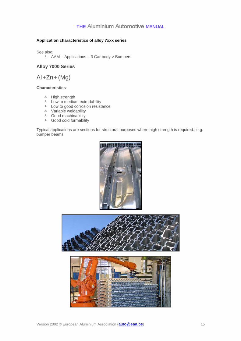
A major part of extrusion based products supplied to the automotive field has over the years been bumper beams in special 7xxx-series alloys (different from aerospace 7xxx alloys).
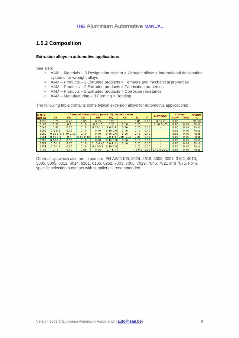
The following table contains some typical extrusion alloys for automotive applications:
Other alloys which also are in use are: EN AW-1100, 2024, 2618, 3003, 3007, 3102, 4010, 5005, 6005, 6012, 6014, 6101, 6106, 6262, 7003, 7005, 7029, 7046, 7021 and 7075. For a specific selection a contact with suppliers is recommended.
AAM – Applications – 1 Power train > Heat exchangers AAM – Products – 3 Automotive tubes > Available forms and thicknesses > Extruded
Alloy 3000 Series
Al + Mn Characteristics:
Excellent thermal conductivity Good weldability Good corrosion resistance Good extrudability Good formability Poor machinability Low to medium strength
The corrosion properties of these alloys are excellent and so is the formability, and the alloys are often used in:
Extruded and drawn tubes Automotive heat exchangers such as radiators, heater cores, air condition coolers
Medium to high strength Low extrudability Good corrosion resistance Good weldability Good machinability and formability
The 5000 alloys combine a wide range of strength, good forming and welding characteristics, and high resistance to general corrosion. Alloys with 1% Mg can be extruded at normal rates, but with higher Mg-content the extrusion speed will be very low. Examples of applications are:
LNG-tanks (liquid natural gas tanks) Decorative alloys with a wide range of strength and bright surface finish capabilities
AAM – Materials – 3 Designation system > Wrought alloys > T-Tempers for heat-treatable wrought alloys (EN 515)
General: Tabled applications were collected in a survey from the participating companies. Note that this is only informational. For details concerning your design please contact your supplier. Remarks: Temper "soft" in this table applies to non-heat treatable alloys and means states F = as fabricated and O = annealed. Hard tempers of heat treatable alloys are labelled T6 = solution treated and artificially aged (for max. strength).
AAM – Products – 2 Extruded products > Profile dimensions > Design guidelines An infinite number of shapes are available. The difficulty of extruding, and thus extrusion cost, depends on shape, size and alloy. Section categories are presented next page. Below, the figure exhibits shape examples used in modern car space frames. Many of those are multi-chamber profiles and many include details facilitating subsequent assembly.
AAM – Applications – 3 Car body > Bumpers AAM – Design – 2 Performance > Crash
Literature:
Laue, K., Stenger, H.: Extrusion, American Society for Metals, 1981. Extruded profiles have been classified according to degree of difficulty. The table (below) lists section categories A through N in increasing order of extrusion difficulty. Categories are illustrated by some sections.
Classification according to degree of difficulty
Ref. K Laue and H Stenger, Extrusion, American Society for Metals, ISBN: 0-87170-094-8
The most clearly extrudable are simple and shaped bars, followed by standard extrusions and simple solid section, semi-hollow sections, section with difficult tongues, tubes, simple hollow sections, difficult hollow sections and the most difficult are wide hollow sections. A major part of sections used in automotive are in the categories D through K. Extrusion cost is strongly related to extrudability and thus section category. However, multi-functional sections will open for more efficient solutions, a higher extrusion cost may frequently be acceptable.
1.7.1 General When designing extrusion-based products, one should note certain limitations and special characteristics with extrusions. In the following, you will find subject like:
There is a considerable cost impact on doing good design. A close dialog with the extruder is therefore recommended to obtain the best possible design. Please note also that some extruders have specialised in certain directions.
R. Cobden: Aluminium: Physical Properties, Characteristics and Alloys. TALAT lecture 1501, EAA, 1994
General Extrusion is a plastic flow process where the material flow speed through the die must be equal at all points of the cross section. The process window is determined by a number of factors that interact and where wall thickness is one parameter. Alloy, and relation between cross section area and billet diameter, are other factors that affect the process. What factors determine minimal wall thickness? Heat generation is a key factor. Pushing aluminium through the die produces heat. The larger the degree of forming, the more heat is generated. High temperature creates problems on the extrusion surface in the form of pick ups and cracks Tolerances are strongly related to wall thickness. If the thickness is too small it will be difficult to ensure proper flow characteristics and therefore small tolerances. Choice of alloy affects the minimum achievable wall thickness. Alloys with a high content of alloying elements are harder to extrude than those with low content, thus requiring thicker walls. Cross section complexity is an influential factor. In general it is easier to produce thin walls in simple sections as compared to those in complex sections. In hollow sections with several channels it can be difficult to fill the cavities between mandrels with metal, c.f. figure below, which in turn may call for increasing wall thickness.
Multi-channel extrusion with thin walls
Getting metal into the thin, inner walls may be quite a challenge
Freedom of design is one of the extrusion processes' true strengths, especially the possibility of putting the material where it is best used.
Still, when designing a thin walled section it is favourable to consider symmetry and constant wall thickness, as these properties contribute to better flow characteristics. It is easier to make thin walls in small extrusions than in large ones. Also, an extrusion press with high specific pressure (ratio between press force and container cross-section) is in general better suited for producing thin walled extrusions.
AAM – Applications – 3 Car body > Bumpers AAM – Design – 2 Performance > Crash
Recommendations The best way to design a thin walled extrusion is by cooperating with an extruder. Each press has its own characteristics and the extruder knows what his press is capable of. The diagram provides a picture of what is possible in terms of wall thickness in relation to circumscribed diameter. These curves will vary for each extrusion press.
Recommended minimal wall thickness for various alloys and section types
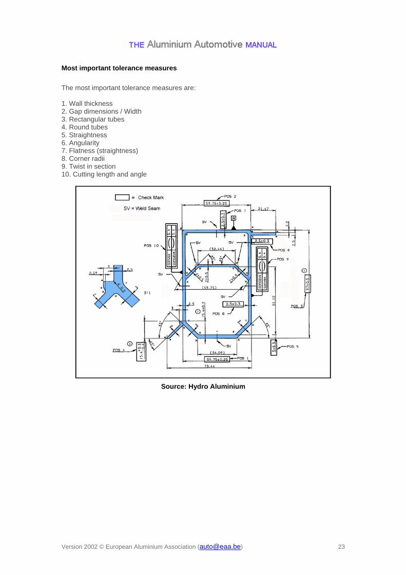
The harder an alloy is to extrude, the more difficult it is to meet dimensional requirements. Tubes can be drawn to closer tolerances, but in general extrusions cannot be drawn. Wide hollow thin-walled extrusions which are difficult to fill with metal, are the most difficult to meet on tolerance requirements. Extrusion tolerances are given in prEN-755-9. Tolerances affect the productivity and thereby the price. Most tolerances are quoted as plus or minus deviation of datum value but, if required, uni-tolerances can be obtained, either all positive or all negative. It is essential, however, to agree this requirement before the die manufacture commences, as the dimensional datum of the die must be altered.
AAM – Materials – 5 Wrought materials production > Extrusion Maximum cross section area is related to billet size / container diameter, which again is related to each specific extrusion press. This corresponds to the green circle in the figure, and maximum theoretical dimension of a quadratic shaped profile is given by the yellow profile. However, in practice an open profile can be produced according to a circumscribed circle of 80 –85 % of the green circle and closed sections 75 – 80 %.
Illustration of possible profile dimensions applying
1. Standard technique and
2. Spreading technique
Some extruders apply a spreading technique, which increases the possible profile dimensions. The red circle indicates the new artificial billet dimension, which in reality is the opening of the pressure ring. The blue rectangular profile indicates maximum possible dimension of open sections, while maximum possible closed sections are somewhat smaller. While most presses have cylindrical billets, some few have rectangular ones for production of wide shallow sections. The maximum size of a profile is also depending of alloy, wall-thickness, cross section complexity and tolerances. Each press has its own possibilities for extrusion width (max. circumference). Typically, the presses dedicated for automotive extrusions range from 1600 tons press force to 6500, and container diameter ranging from 185 mm to 340 mm.
Laue, K., Stenger, H.: Extrusion, American Society for Metals, 1981. Ostermann, F., Anwendungstechnologie Aluminium, Berlin, Heidelberg, London, New
York, Tokyo: Springer-Verlag, 1998, ISBN 3-540-62706-5 — [Lit. 1] The three figures below illustrate some guidelines and practical hints: 1. Design guidelines for improved extrudability and thus reduced cost. 2. Some design hints improving assembly and making attachments to the profile easier. Some typical extrusion designs improving structural stability and some other details improving functionality. Remember also the use of inner and outer fins when stiffness is demanded.
AAM – Materials – 3 Designation system > Wrought alloys > Temper designation system for wrought alloys (EN 515)
AAM – Products – 3 Automotive tubes > Mechanical properties Extrusion tempers: Non heat treatable alloys, 1xxx-, 3xxx- and 5xxx-series, are mostly delivered in temper F. 6xxx-series alloys are normally delivered in temper T5. 7xxx-alloys are usually solution heat treated before artificial ageing and are therefore delivered in temper T6 and in some cases T7, which is an over-aged temper improving toughness. Static properties: Static properties in the following table are given as typical only. Min. values are given in EN 755-2. Several suppliers of extrusions offer their own alloy(s) within the standard alloy, and also their own property limits. Statistics on open versus closed sections of alloy 7108 show that closed sections of equal thickness are about 10 MPa lower in tensile and yield strength, and approx. 3% higher in elongation (A5).
Source: Hydro
Static properties differ in various directions of the profile. In general static properties are given in the longitudinal direction of the extrusion.
Fig. 1 and 2 show representative tensile tests in various directions for alloy 7108-T5 in which the grains are fibrous non-recrystallised. The tensile properties of a recrystallised profile are somewhat different.
Fig. 3 and 4 for alloy 6063-T1 demonstrate some difference from figs. 1-2. Strain to fracture is lower in L and T direction than in 45o and much more evident in the recrystallised 6063. It should be noticed that in temper T1 the strength level is lower than in T5, but the principal shape of each curve is equal. The effect demonstrated above is texture effects and applies also to sheet material. Other static properties of relevance may be creep, compression, bearing, shear, creep and properties at elevated and low temperatures. For those, see Materials (general) and Talat.
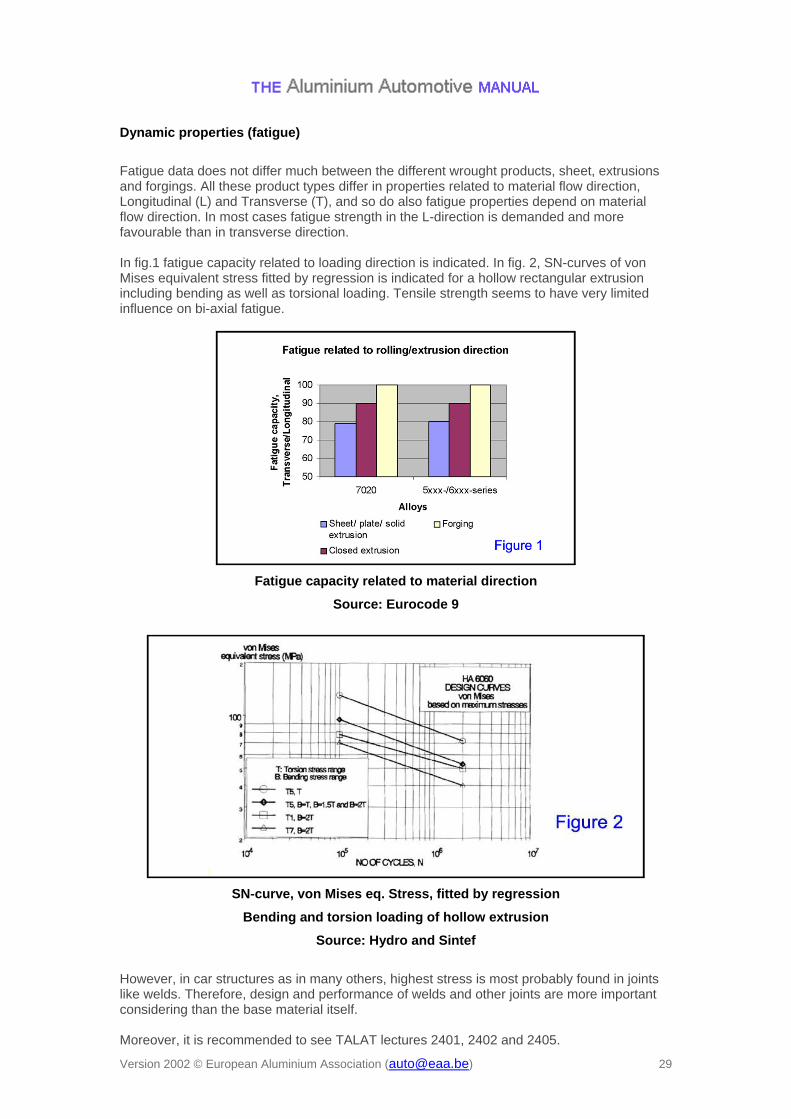
Fatigue data does not differ much between the different wrought products, sheet, extrusions and forgings. All these product types differ in properties related to material flow direction, Longitudinal (L) and Transverse (T), and so do also fatigue properties depend on material flow direction. In most cases fatigue strength in the L-direction is demanded and more favourable than in transverse direction. In fig.1 fatigue capacity related to loading direction is indicated. In fig. 2, SN-curves of von Mises equivalent stress fitted by regression is indicated for a hollow rectangular extrusion including bending as well as torsional loading. Tensile strength seems to have very limited influence on bi-axial fatigue.
Fatigue capacity related to material direction
Source: Eurocode 9
SN-curve, von Mises eq. Stress, fitted by regression
Bending and torsion loading of hollow extrusion
Source: Hydro and Sintef
However, in car structures as in many others, highest stress is most probably found in joints like welds. Therefore, design and performance of welds and other joints are more important considering than the base material itself. Moreover, it is recommended to see TALAT lectures 2401, 2402 and 2405.
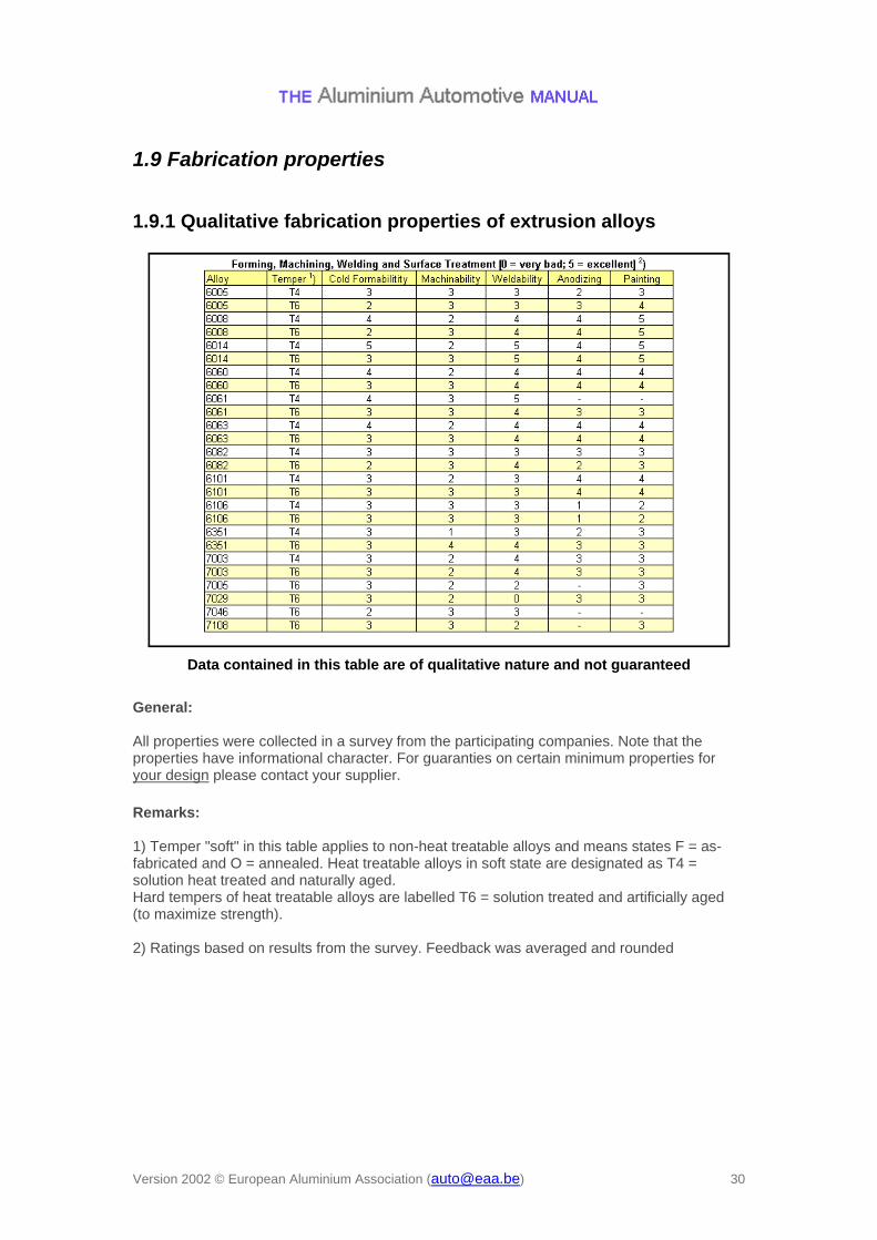
1.9.1 Qualitative fabrication properties of extrusion alloys
Data contained in this table are of qualitative nature and not guaranteed
General: All properties were collected in a survey from the participating companies. Note that the properties have informational character. For guaranties on certain minimum properties for your design please contact your supplier.
Remarks: 1) Temper "soft" in this table applies to non-heat treatable alloys and means states F = as-fabricated and O = annealed. Heat treatable alloys in soft state are designated as T4 = solution heat treated and naturally aged. Hard tempers of heat treatable alloys are labelled T6 = solution treated and artificially aged (to maximize strength). 2) Ratings based on results from the survey. Feedback was averaged and rounded
The flow curve, related to the true cross section area, can be described by Ludwik's law:
where K is the flow resistance (constant), and n is the strain-hardening coefficient. The flow curve usually depends on orientation w.r.t. extrusion direction (anisotropy, press effect). Formability of extrusions is depending on:
the ductility, critical, where necking occurs. the strain hardening, n-value, which influence the ability to distribute the strain. the anisotropy, influencing the deformation in different orientations.
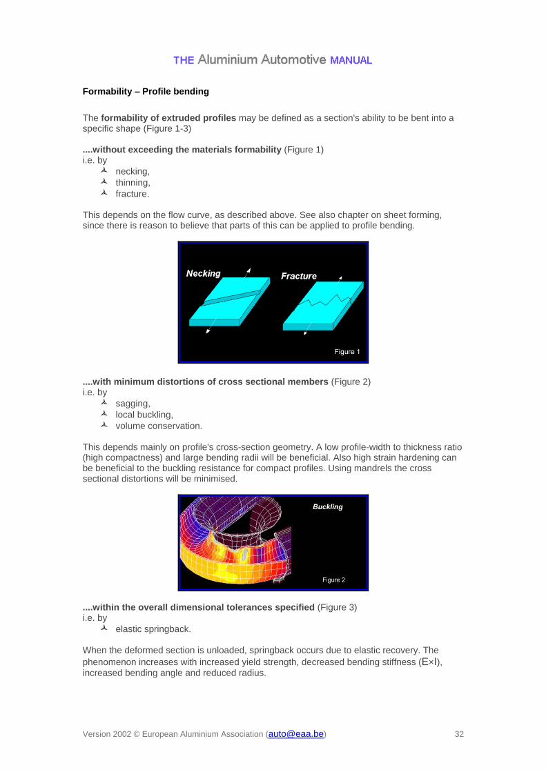
The formability of extruded profiles may be defined as a section's ability to be bent into a specific shape (Figure 1-3) ....without exceeding the materials formability (Figure 1) i.e. by
necking, thinning, fracture.
This depends on the flow curve, as described above. See also chapter on sheet forming, since there is reason to believe that parts of this can be applied to profile bending.
....with minimum distortions of cross sectional members (Figure 2) i.e. by
sagging, local buckling, volume conservation.
This depends mainly on profile's cross-section geometry. A low profile-width to thickness ratio (high compactness) and large bending radii will be beneficial. Also high strain hardening can be beneficial to the buckling resistance for compact profiles. Using mandrels the cross sectional distortions will be minimised.
....within the overall dimensional tolerances specified (Figure 3) i.e. by
elastic springback. When the deformed section is unloaded, springback occurs due to elastic recovery. The
phenomenon increases with increased yield strength, decreased bending stiffness (E×I), increased bending angle and reduced radius.
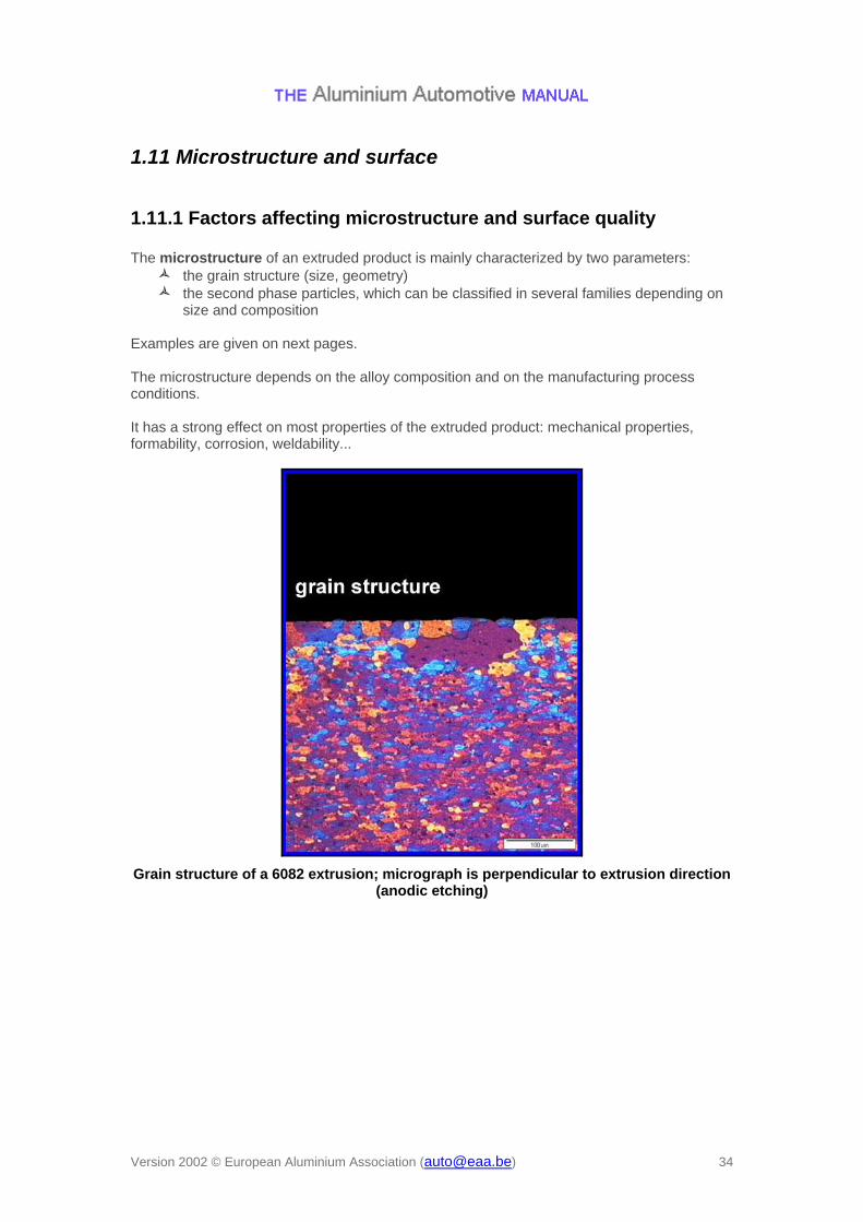
1.11.1 Factors affecting microstructure and surface quality The microstructure of an extruded product is mainly characterized by two parameters:
the grain structure (size, geometry) the second phase particles, which can be classified in several families depending on
size and composition Examples are given on next pages. The microstructure depends on the alloy composition and on the manufacturing process conditions. It has a strong effect on most properties of the extruded product: mechanical properties, formability, corrosion, weldability...
Grain structure of a 6082 extrusion; micrograph is perpendicular to extrusion direction (anodic etching)
Particle distribution in a 6082 extrusion, perpendicular to extrusion direction
The surface quality of an extruded product depends mainly on the extrusion process conditions, but also on alloy composition and on handling / transport / storage conditions. The surface quality requirements depend on the final application: are there visible parts? Is there a surface treatment? … These questions should be clarified early between the producer and the customer since they can impact the extrusion process conditions. Several kinds of surface defects can be encountered on extruded products. Examples are given next pages.
1.11.3 Second phase particles Typical size range: 1 to 20 microns The particles found in this range are:
Fe and Si intermetallic phases which are always present in the microstructure. Large Mg2Si precipitates which may be present if process conditions did not allow
their complete dissolution.
AlFeSi intermetallic phases (light grey) and undissolved Mg2Si precipitates (black) in a 6082 extrusion (optical microscope)
Typical size range: 0.1 to 1 µm. When addition elements like Mn or Cr are present, they form small particles called dispersoïds. These particles are used to control recrystallized grain size or to obtain a fibrous grain structure. They are smaller and denser than the intermetallic phases.
Fine AlMn dispersoïds and large AlFeSi intermetallic phases in a 3103 extrusion (scanning electron microscope)
Typical size range: 0.01 to 0.2 µm. In age hardening alloys, addition elements precipitate during final thermal treatment to form hardening precipitates. They strongly increase the mechanical properties of the product. Automotive extrusions made of 6xxx or 7xxx series in the T4 and T6 temper will contain such hardening particles.
Hardening needle-like Mg2Si precipitates in a 6xxx alloy
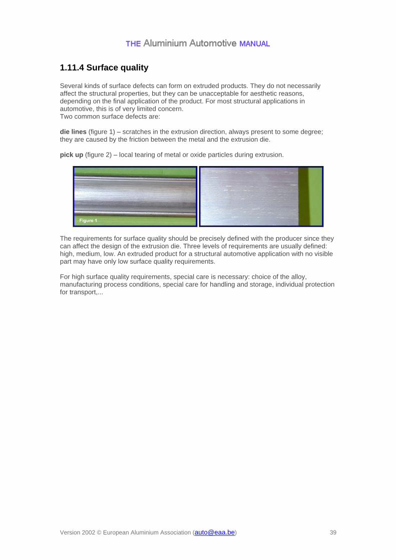
1.11.4 Surface quality Several kinds of surface defects can form on extruded products. They do not necessarily affect the structural properties, but they can be unacceptable for aesthetic reasons, depending on the final application of the product. For most structural applications in automotive, this is of very limited concern. Two common surface defects are: die lines (figure 1) – scratches in the extrusion direction, always present to some degree; they are caused by the friction between the metal and the extrusion die. pick up (figure 2) – local tearing of metal or oxide particles during extrusion.
The requirements for surface quality should be precisely defined with the producer since they can affect the design of the extrusion die. Three levels of requirements are usually defined: high, medium, low. An extruded product for a structural automotive application with no visible part may have only low surface quality requirements. For high surface quality requirements, special care is necessary: choice of the alloy, manufacturing process conditions, special care for handling and storage, individual protection for transport,...
1.11.6 Electrolytic and chemical polishing These two polishing methods are used very often prior to anodising in order to obtain a bright surface appearance. In this case the process is called bright anodising. Chemical polishing is used more often than electrolytic polishing. The methods are especially suitable for complex profile geometry where mechanical polishing is difficult. Sometimes mechanical polishing is used prior to electrolytic / chemical polishing when mirror gloss appearance is required. Example of electrolytic polishing is the "Brytal" process. Examples of chemical polishing are Acid-cleaning, Glossing, buffing, Chromating and Phosphatising.
Electrolytic polishing: Electrolytic polishing is carried out by means of current, special chemicals end high temperature. The "Brytal" process is one of the commercial electrolytic polishing processes, and with this process it is possible to obtain mirror finishes on large flat areas. The profiles should be carefully polishes by mechanical means before treatment. Chemical polishing: Chemical polishing is carried out by means of special chemicals (like Phosphoric Acid, Nitric Acid and Sulphuric Acid) and high temperature. Mirror-like surfaces are generally produced in mixtures of Phosphoric and Nitric Acids to which numerous other additions can be made to secure a higher levelling action. Sulphuric Acid is very often added to the mixture to remove or minimise the die lines.
1.11.7 Anodising Preface Anodising is an artificial re-building of the oxide layer by use of current and an electrolyte (normally Sulphuric Acid). The thickness of the layer is dependant on the service-conditions. For indoor (automotive?)
use the thickness is typically from 3-15 m, and for outdoor (automotive?) use the layer
should be between 15-20 m or even thicker depending on required service life. The anodic oxide coating improves some major properties of aluminium.
Properties and process Response to colouring. Mainly brown shade colours suitable for outdoor use. Many colours available for indoor use. Generally, all colours are heat sensitive by fading Corrosion resistance. A low porosity oxide film has a good resistance against pitting corrosion. Chloride ions have little effect on a uniform layer. Wear resistance. Anodising improves wear resistance. Especially hard anodising increases the abrasion properties, but also normal architectural anodising gives better wear resistance. Surface hardness. Normal architectural anodising increase the surface hardness from 60-130 HV to 200-350 HV. Electrical resistance. The anodic oxide layer has high electrical resistance. Anodised aluminium is suitable for electrical components, e.g. transformers and capacitors.
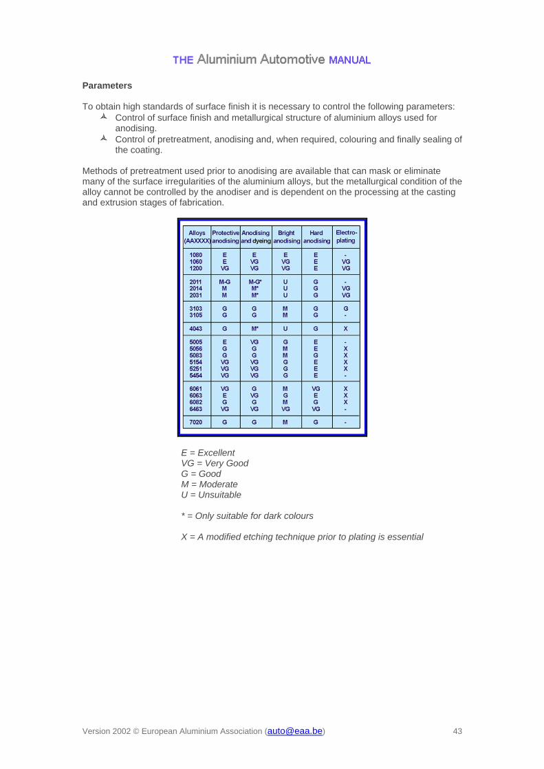
Parameters To obtain high standards of surface finish it is necessary to control the following parameters:
Control of surface finish and metallurgical structure of aluminium alloys used for anodising.
Control of pretreatment, anodising and, when required, colouring and finally sealing of the coating.
Methods of pretreatment used prior to anodising are available that can mask or eliminate many of the surface irregularities of the aluminium alloys, but the metallurgical condition of the alloy cannot be controlled by the anodiser and is dependent on the processing at the casting and extrusion stages of fabrication.
E = Excellent VG = Very Good G = Good M = Moderate U = Unsuitable * = Only suitable for dark colours X = A modified etching technique prior to plating is essential
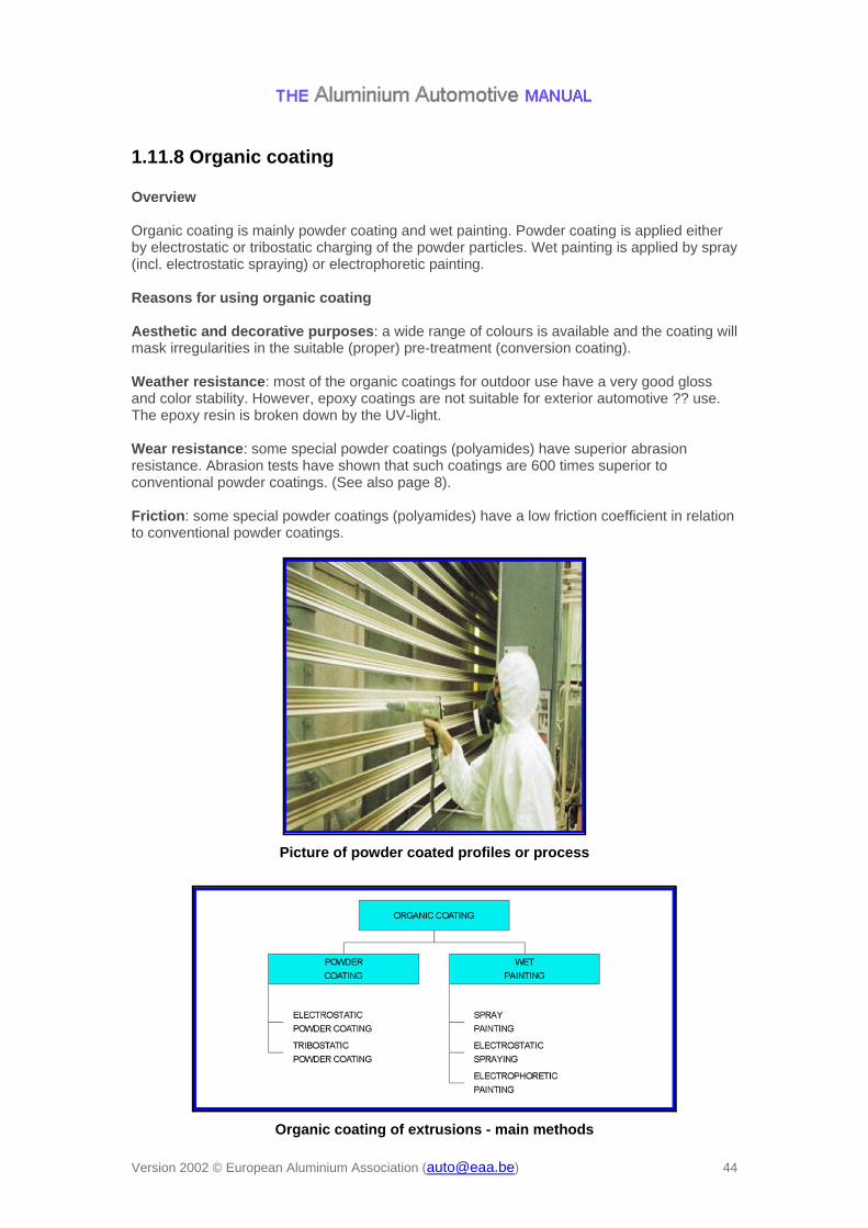
1.11.8 Organic coating Overview Organic coating is mainly powder coating and wet painting. Powder coating is applied either by electrostatic or tribostatic charging of the powder particles. Wet painting is applied by spray (incl. electrostatic spraying) or electrophoretic painting. Reasons for using organic coating Aesthetic and decorative purposes: a wide range of colours is available and the coating will mask irregularities in the suitable (proper) pre-treatment (conversion coating). Weather resistance: most of the organic coatings for outdoor use have a very good gloss and color stability. However, epoxy coatings are not suitable for exterior automotive ?? use. The epoxy resin is broken down by the UV-light. Wear resistance: some special powder coatings (polyamides) have superior abrasion resistance. Abrasion tests have shown that such coatings are 600 times superior to conventional powder coatings. (See also page 8). Friction: some special powder coatings (polyamides) have a low friction coefficient in relation to conventional powder coatings.
1.11.9 Metal plating Metal plating is deposition of a metal layer on another metal or plastic substrate. The precipitation occurs usually from a solution which contains ions of the metal used for the coating. Plating could either be carried out by means of electro- deposition, electroless deposition or mechanical deposition of a metal. The main reasons for plating on aluminium are:
Formation of an attractive finish, Increased corrosion resistance, Increased surface hardness, Increased solder ability / braze ability.
Application to alloys: 6060: Suitable for decorative and protective anodising, organic coating and metal plating 6005 and 6082: Suitable for protective anodising and organic coating. Less suitable for decorative anodising and decorative metal plating due to a gray (black) appearance. Surface appearance may be improved by proper desmutting after alkaline etching. However, a modified etching technique prior to metal plating is essential. Suitable for functional (not decorative) metal plating.
1.12.1 General survey of corrosion resistance of automotive extrusions
See also:
AAM – Materials – 4 Microstructure and properties > Corrosion behaviour > Protective oxide film
Corrosion of extrusions does not differ much from corrosion of rolled products. However, some aspects is worth mentioning.
Pitting corrosion may occur in lines along the extrusion direction as a result of iron-containing particles broken up and lined during extrusion.
Abrupt changes in grain size as a result of high strain rate differences may cause galvanic effects and cause galvanic corrosion in shape end surfaces and drilled and punched holes.
Part of the heat affected zone of some welded 7xxx-series alloys is a preferred corrosion zone.
Several alloys of the 7xxx-series are susceptible to stress corrosion. Welding creates residual stresses and welding of these alloys should be thoroughly evaluated with regard to environment and loading
See also more detailed information on corrosion of aluminium alloys in Materials (general)
1.13.1 Brief summary of thermal stability of extrusions See also:
AAM – Products – 1 Rolled products > Thermal stability Thermal stability of extrusions is very similar to rolled products. Briefly summarised: Age hardening alloys in temper T4 will increase strength over time, and the rate of hardening increases with increasing temperature. At room temperature, the hardening should be considered completed after about 2 years. Alloys containing more alloying elements will increase in strength more and faster than those lower alloyed. 7xxx-alloys age harden faster than 6xxx-alloys. In all tempers, extrusions will loose strength when exposed to elevated temperatures. At temperatures as low as 100 deg. C, yield strength is as low as about 90 % of RT strength. From temperatures of about 140 deg. C and above, increased exposure time decreases strength. After 1000 h exposure at 250 deg. C, YS is about 20 % of the unexposed YS at RT.
fatigue AAM – Design – 2 Performance > Fatigue > Investigation of service failures in
aluminium products Literature:
Lahaye, C.T.W.: An empirical method to predict paint appearance starting with substrate roughness data. Proc. IBEC96, (1996)
Fatigue fracture in automotive extrusions is rarely experienced as dimensioning usually is done for peak loads as crash, but some extrusion characteristics should be noticed w.r.t. fatigue. In general, fatigue properties of extrusions do not differ much from those of sheet. The most important factors are notch effects created by joints of various types, by surface topography, internal defects of various size (inclusions, extrusion welds,...), and changes in microstructure (recrystallised coarse grained surface layer and fibrous inner grains). Closed sections contain pressure welds, i.e. during the extrusion process the material has been divided into several „rivers", passing the bearing bridges of the mandrel, and then being press-welded behind the bridges. This is an important quality measure of a hollow extrusion. If these welds are not properly closed/ press welded, defects occur and tensile and fatigue properties in the transverse direction will be influenced. Moreover, design of the extrusion will also influence on fatigue, again by notch effects from the shape. Influencing factors are sharp corners and sharp changes in profile thickness. Corrosion will also influence fatigue by way of creating notches. Surface effects may create lined pitting corrosion attacks and thus make stress raisers in the transverse direction. Local abrupt changes in grain size may also cause notch effects and thus influence fatigue performance. From the figure shown in Materials > Microstructure and properties > Mechanical properties > Fatigue, it can be seen that fatigue strength in general is about 1/3 of tensile strength while notch fatigue properties are almost independent of alloy and static strength.
Fusion welding (MIG and TIG and laser) Hybrid laser technique (laser/MIG) Friction Stir Welding Spot welding Blind rivets Self piercing rivets Clinching bolting and Adhesive bonding Compression Fit Joint
All these methods are described in section Manufacturing > Joining. In this section those methods that have special relevance for extrusions will be described.
AAM – Joining – 1 Fusion welding MIG welding is commonly used and can be applied within the whole range of extrusion thicknesses of practical interest. In cases like T- and K-joints welding is the only well developed joining technique. The method is well suited for automation and is therefore an attractive candidate for high-volume production. Proper choice of filler material reduces the risk of solidification cracking. Other advantages include high productivity and robustness. TIG welding is an alternative method particularly in welding of thin walled extrusions where close control of penetration and quality is crucial. Laser welding (CO2, YAG and diode) gives high heat intensity causing a correspondingly narrow heat affected zone and low distortions. However, the method requires very tight fit-up of the parts to be welded, and can usually not accept gaps larger than about 0.2mm, which means that the method requires tight tolerances. The hybrid laser technique, which combines a laser and a MIG heat source, utilises the advantages of both methods and can therefore accept larger gaps than the laser method alone. Due to the high heat input, the method offers very high travel speeds. Plasma-arc welding is another highly efficient joining method which yields a very confined local heating due to an intensively heated plasma arc.
1.16.3 Welding simulation Thermally induced deformations are unavoidable in fusion welding and may represent a challenge to overcome due to tight geometrical tolerance limits. Another phenomena is degradation of the base material due to softening of the HAZ. Recent advances in development of numerical weld simulation tools can now significantly reduce these problems, since such tools can be applied to optimise the welding parameters, as well the fixture and clamping system. The right hand figure shows an example of output from a typical weld simulation applying the toolbox WELDSIM *). The component is a corner of a windshield frame and the colours represent different yield stress levels. (The red colour corresponds to unaffected base material while the dark blue colour symbolises severe softening). Several software programs calculating distortions are commercially available. ____________________ *) Not commercially available yet, for information, contact Hydro Automotive Structures.
Simulated yield stress after welding of a windshield frame
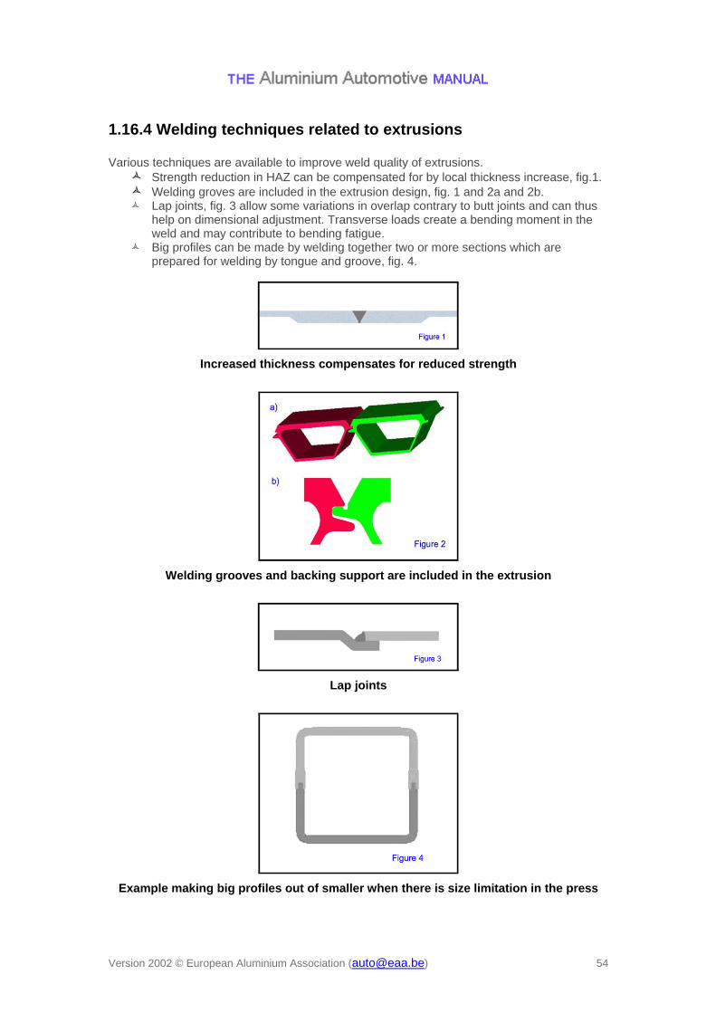
1.16.4 Welding techniques related to extrusions Various techniques are available to improve weld quality of extrusions.
Strength reduction in HAZ can be compensated for by local thickness increase, fig.1. Welding groves are included in the extrusion design, fig. 1 and 2a and 2b. Lap joints, fig. 3 allow some variations in overlap contrary to butt joints and can thus
help on dimensional adjustment. Transverse loads create a bending moment in the weld and may contribute to bending fatigue.
Big profiles can be made by welding together two or more sections which are prepared for welding by tongue and groove, fig. 4.
Increased thickness compensates for reduced strength
Welding grooves and backing support are included in the extrusion
Lap joints
Example making big profiles out of smaller when there is size limitation in the press
AAM – Joining – 6 Adhesive bonding The experience with adhesive bonding of automotive structures is rather limited. The only known space frame structure currently in production applying adhesive bonding are the Lotus Elise (since 1996) and the Aston Martin Vanquish. When bonding, in general the design must match the fact that bonding surfaces need to be much larger than those used when welding. The forces working on the bonded material should be shear loads, and peel load should be avoided, fig. 1.
Longitudinal joining of extrusions or sheet to extrusion by adhesive bonding is excellent, but T-joints and similar joints can also be made when proper design is used, fig. 2.
Adhesive bonding makes no thermal distortion and no changes in material characteristics. When two large closed sections are to be joined longitudinally and access from inside is very limited, adhesive bonding should be considered, fig. 3.
Normally extrusions are thin-walled, which means welding need more attention