Pro | ENGINEER ® WILDFIRE ™ 3.0 Tutorial and MultiMedia CD Roger Toogood, Ph.D., P. Eng. SDC Schroff Development Corporation www.schroff.com www.schroff-europe.com PUBLICATIONS INSIDE: MultiMedia CD An audio/visual presentation of the tutorial projects
Transcript
Pro | ENGINEER®
W I L D F I R E ™ 3.0
Tutorial and MultiMedia CD
Roger Toogood, Ph.D., P. Eng.
SDC
Schroff Development Corporation
www.schroff.com
www.schroff-europe.com
PUBLICATIONS
INSIDE:
MultiMedia CD
An audio/visual presentation of the
tutorial projects
Copyrighted Material
Copyrighted
Material
Copyrighted Material
Copyrighted
Material
Creating a Simple Object (Part I) 2 - 1
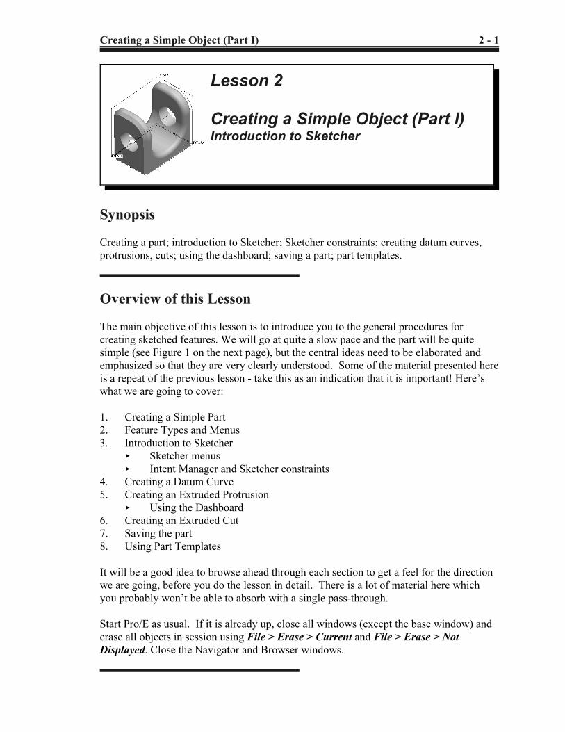
Lesson 2
Creating a Simple Object (Part I)Introduction to Sketcher
Synopsis
Creating a part; introduction to Sketcher; Sketcher constraints; creating datum curves,
protrusions, cuts; using the dashboard; saving a part; part templates.
Overview of this Lesson
The main objective of this lesson is to introduce you to the general procedures for
creating sketched features. We will go at quite a slow pace and the part will be quite
simple (see Figure 1 on the next page), but the central ideas need to be elaborated and
emphasized so that they are very clearly understood. Some of the material presented here
is a repeat of the previous lesson - take this as an indication that it is important! Here’s
what we are going to cover:
1. Creating a Simple Part
2. Feature Types and Menus
3. Introduction to Sketcher
< Sketcher menus
< Intent Manager and Sketcher constraints
4. Creating a Datum Curve
5. Creating an Extruded Protrusion
< Using the Dashboard
6. Creating an Extruded Cut
7. Saving the part
8. Using Part Templates
It will be a good idea to browse ahead through each section to get a feel for the direction
we are going, before you do the lesson in detail. There is a lot of material here which
you probably won’t be able to absorb with a single pass-through.
Start Pro/E as usual. If it is already up, close all windows (except the base window) and
erase all objects in session using File > Erase > Current and File > Erase > Not
Displayed. Close the Navigator and Browser windows.
Copyrighted Material
Copyrighted
Material
Copyrighted Material
Copyrighted
Material
2 - 2 Creating a Simple Object (Part I)
Figure 2 Creating a new partFigure 1 Part at the end of this lesson
Creating a Simple Part
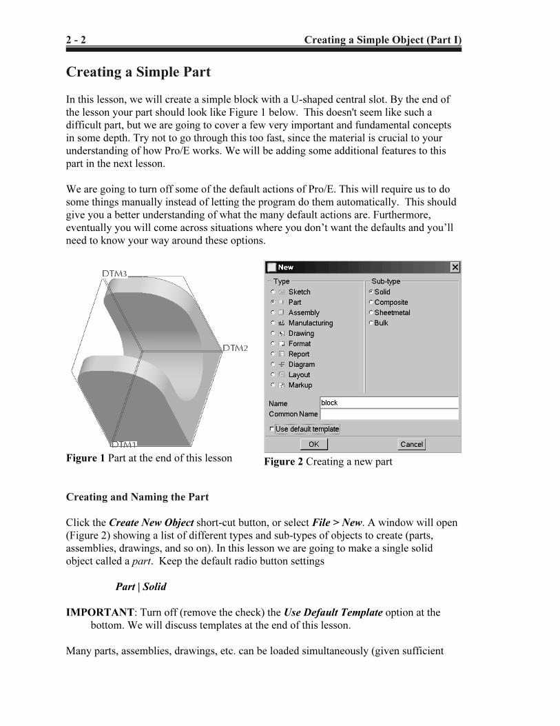
In this lesson, we will create a simple block with a U-shaped central slot. By the end of
the lesson your part should look like Figure 1 below. This doesn't seem like such a
difficult part, but we are going to cover a few very important and fundamental concepts
in some depth. Try not to go through this too fast, since the material is crucial to your
understanding of how Pro/E works. We will be adding some additional features to this
part in the next lesson.
We are going to turn off some of the default actions of Pro/E. This will require us to do
some things manually instead of letting the program do them automatically. This should
give you a better understanding of what the many default actions are. Furthermore,
eventually you will come across situations where you don’t want the defaults and you’ll
need to know your way around these options.
Creating and Naming the Part
Click the Create New Object short-cut button, or select File > New. A window will open
(Figure 2) showing a list of different types and sub-types of objects to create (parts,
assemblies, drawings, and so on). In this lesson we are going to make a single solid
object called a part. Keep the default radio button settings
Part | Solid
IMPORTANT: Turn off (remove the check) the Use Default Template option at the
bottom. We will discuss templates at the end of this lesson.
Many parts, assemblies, drawings, etc. can be loaded simultaneously (given sufficient
Copyrighted Material
Copyrighted
Material
Copyrighted Material
Copyrighted
Material
Creating a Simple Object (Part I) 2 - 3
1 Pro/E can keep track of objects of different types with the same names. A part
and a drawing can have the same name since they are different object types.
Datum Axis
Datum Plane
Datum Curve
Sketched Curve
Datum Point
Coord System
Figure 4 Toolbar buttons for creating
DATUMS
Figure 3 Options for new parts
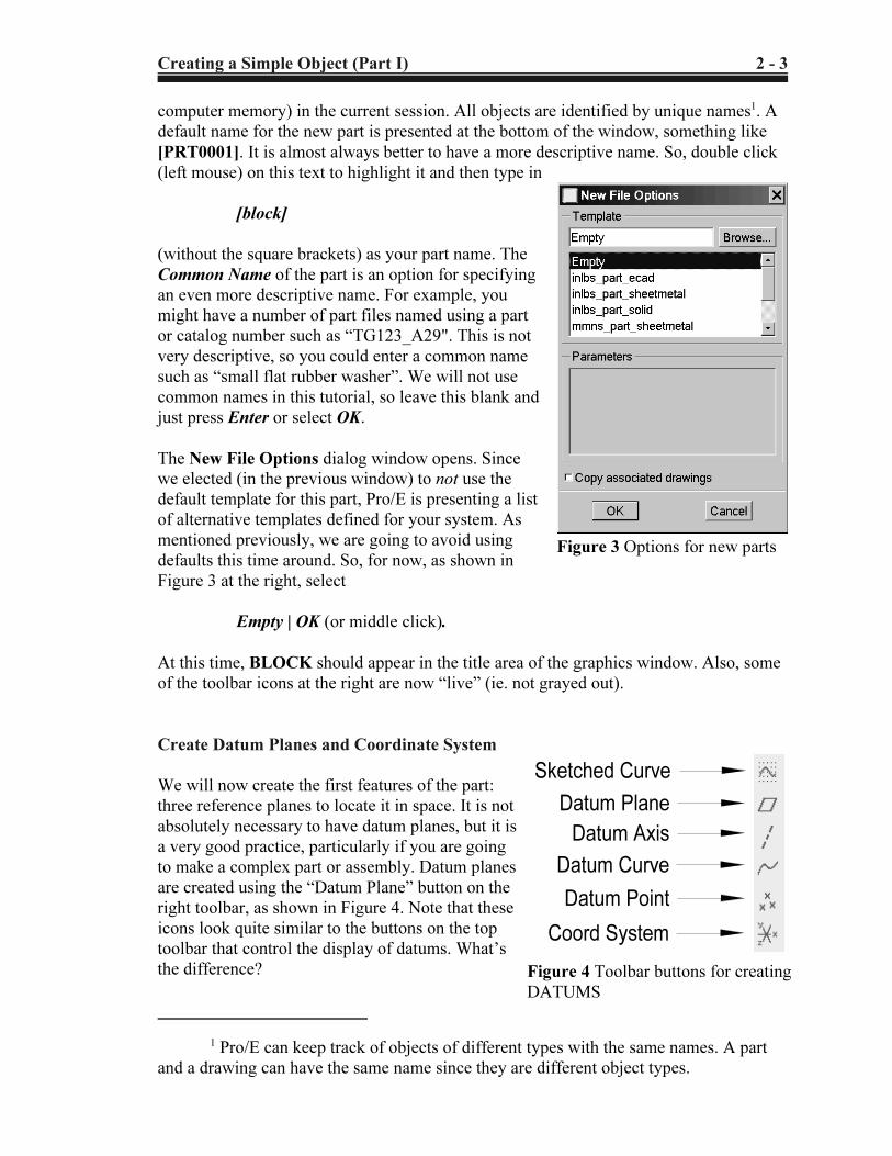
computer memory) in the current session. All objects are identified by unique names1. A
default name for the new part is presented at the bottom of the window, something like
[PRT0001]. It is almost always better to have a more descriptive name. So, double click
(left mouse) on this text to highlight it and then type in
[block]
(without the square brackets) as your part name. The
Common Name of the part is an option for specifying
an even more descriptive name. For example, you
might have a number of part files named using a part
or catalog number such as “TG123_A29". This is not
very descriptive, so you could enter a common name
such as “small flat rubber washer”. We will not use
common names in this tutorial, so leave this blank and
just press Enter or select OK.
The New File Options dialog window opens. Since
we elected (in the previous window) to not use the
default template for this part, Pro/E is presenting a list
of alternative templates defined for your system. As
mentioned previously, we are going to avoid using
defaults this time around. So, for now, as shown in
Figure 3 at the right, select
Empty | OK (or middle click).
At this time, BLOCK should appear in the title area of the graphics window. Also, some
of the toolbar icons at the right are now “live” (ie. not grayed out).
Create Datum Planes and Coordinate System
We will now create the first features of the part:
three reference planes to locate it in space. It is not
absolutely necessary to have datum planes, but it is
a very good practice, particularly if you are going
to make a complex part or assembly. Datum planes
are created using the “Datum Plane” button on the
right toolbar, as shown in Figure 4. Note that these
icons look quite similar to the buttons on the top
toolbar that control the display of datums. What’s
the difference?
Copyrighted Material
Copyrighted
Material
Copyrighted Material
Copyrighted
Material
2 - 4 Creating a Simple Object (Part I)
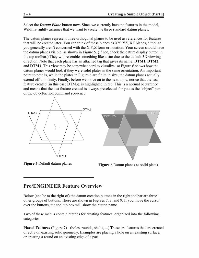
Figure 5 Default datum planes Figure 6 Datum planes as solid plates
Select the Datum Plane button now. Since we currently have no features in the model,
Wildfire rightly assumes that we want to create the three standard datum planes.
The datum planes represent three orthogonal planes to be used as references for features
that will be created later. You can think of these planes as XY, YZ, XZ planes, although
you generally aren’t concerned with the X,Y,Z form or notation. Your screen should have
the datum planes visible, as shown in Figure 5. (If not, check the datum display button in
the top toolbar.) They will resemble something like a star due to the default 3D viewing
direction. Note that each plane has an attached tag that gives its name: DTM1, DTM2,
and DTM3. This view may be somewhat hard to visualize, so Figure 6 shows how the
datum planes would look if they were solid plates in the same orientation. An important
point to note is, while the plates in Figure 6 are finite in size, the datum planes actually
extend off to infinity. Finally, before we move on to the next topic, notice that the last
feature created (in this case DTM3), is highlighted in red. This is a normal occurrence
and means that the last feature created is always preselected for you as the “object” part
of the object/action command sequence.
Pro/ENGINEER Feature Overview
Below (and/or to the right of) the datum creation buttons in the right toolbar are three
other groups of buttons. These are shown in Figures 7, 8, and 9. If you move the cursor
over the buttons, the tool tip box will show the button name.
Two of these menus contain buttons for creating features, organized into the following
categories:
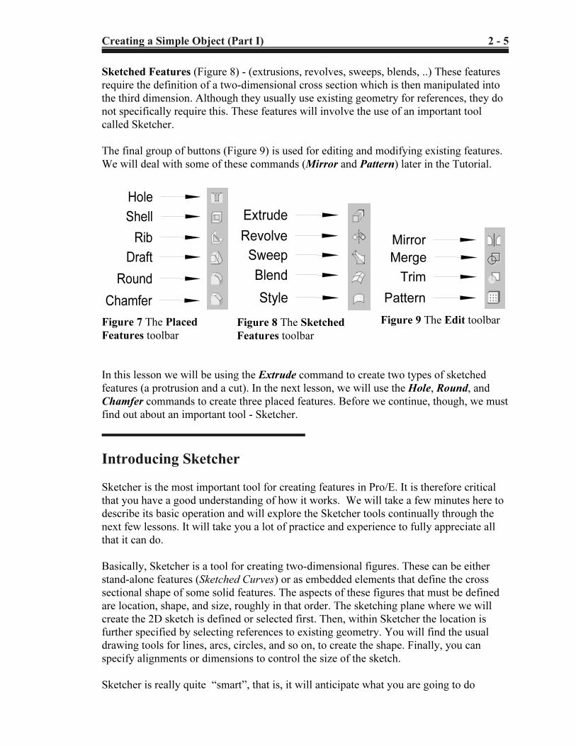
Placed Features (Figure 7) - (holes, rounds, shells, ...) These are features that are created
directly on existing solid geometry. Examples are placing a hole on an existing surface,
or creating a round on an existing edge of a part.
Copyrighted Material
Copyrighted
Material
Copyrighted Material
Copyrighted
Material
Creating a Simple Object (Part I) 2 - 5
Hole
Shell
Rib
Draft
Round
Chamfer
Figure 7 The Placed
Features toolbar
Extrude
Revolve
Sweep
Blend
Style
Figure 8 The Sketched
Features toolbar
Mirror
Merge
Trim
Pattern
Figure 9 The Edit toolbar
Sketched Features (Figure 8) - (extrusions, revolves, sweeps, blends, ..) These features
require the definition of a two-dimensional cross section which is then manipulated into
the third dimension. Although they usually use existing geometry for references, they do
not specifically require this. These features will involve the use of an important tool
called Sketcher.
The final group of buttons (Figure 9) is used for editing and modifying existing features.
We will deal with some of these commands (Mirror and Pattern) later in the Tutorial.
In this lesson we will be using the Extrude command to create two types of sketched
features (a protrusion and a cut). In the next lesson, we will use the Hole, Round, and
Chamfer commands to create three placed features. Before we continue, though, we must
find out about an important tool - Sketcher.
Introducing Sketcher
Sketcher is the most important tool for creating features in Pro/E. It is therefore critical
that you have a good understanding of how it works. We will take a few minutes here to
describe its basic operation and will explore the Sketcher tools continually through the
next few lessons. It will take you a lot of practice and experience to fully appreciate all
that it can do.
Basically, Sketcher is a tool for creating two-dimensional figures. These can be either
stand-alone features (Sketched Curves) or as embedded elements that define the cross
sectional shape of some solid features. The aspects of these figures that must be defined
are location, shape, and size, roughly in that order. The sketching plane where we will
create the 2D sketch is defined or selected first. Then, within Sketcher the location is
further specified by selecting references to existing geometry. You will find the usual
drawing tools for lines, arcs, circles, and so on, to create the shape. Finally, you can
specify alignments or dimensions to control the size of the sketch.
Sketcher is really quite “smart”, that is, it will anticipate what you are going to do
Copyrighted Material
Copyrighted
Material
Copyrighted Material
Copyrighted
Material
2 - 6 Creating a Simple Object (Part I)
2 Intent Manager was introduced several releases ago. Some veteran Pro/E users
still have not made the switch from “the old days”. For those users, Pro/E has the ability
to turn off the Intent Manager and let them do everything manually.
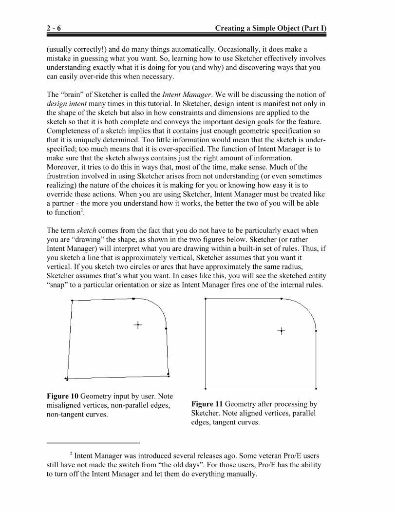
Figure 11 Geometry after processing by
Sketcher. Note aligned vertices, parallel
edges, tangent curves.
Figure 10 Geometry input by user. Note
misaligned vertices, non-parallel edges,
non-tangent curves.
(usually correctly!) and do many things automatically. Occasionally, it does make a
mistake in guessing what you want. So, learning how to use Sketcher effectively involves
understanding exactly what it is doing for you (and why) and discovering ways that you
can easily over-ride this when necessary.
The “brain” of Sketcher is called the Intent Manager. We will be discussing the notion of
design intent many times in this tutorial. In Sketcher, design intent is manifest not only in
the shape of the sketch but also in how constraints and dimensions are applied to the
sketch so that it is both complete and conveys the important design goals for the feature.
Completeness of a sketch implies that it contains just enough geometric specification so
that it is uniquely determined. Too little information would mean that the sketch is under-
specified; too much means that it is over-specified. The function of Intent Manager is to
make sure that the sketch always contains just the right amount of information.
Moreover, it tries to do this in ways that, most of the time, make sense. Much of the
frustration involved in using Sketcher arises from not understanding (or even sometimes
realizing) the nature of the choices it is making for you or knowing how easy it is to
override these actions. When you are using Sketcher, Intent Manager must be treated like
a partner - the more you understand how it works, the better the two of you will be able
to function2.
The term sketch comes from the fact that you do not have to be particularly exact when
you are “drawing” the shape, as shown in the two figures below. Sketcher (or rather
Intent Manager) will interpret what you are drawing within a built-in set of rules. Thus, if
you sketch a line that is approximately vertical, Sketcher assumes that you want it
vertical. If you sketch two circles or arcs that have approximately the same radius,
Sketcher assumes that’s what you want. In cases like this, you will see the sketched entity
“snap” to a particular orientation or size as Intent Manager fires one of the internal rules.
Copyrighted Material
Copyrighted
Material
Copyrighted Material
Copyrighted
Material
Creating a Simple Object (Part I) 2 - 7
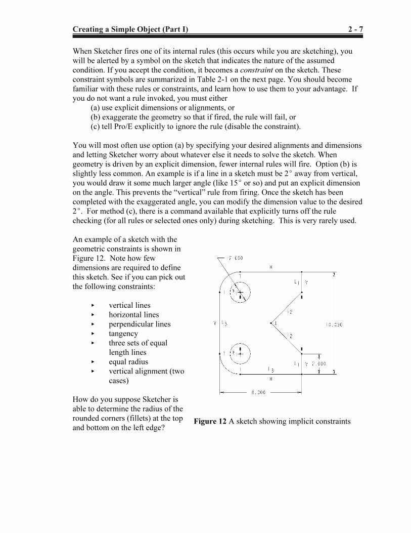
Figure 12 A sketch showing implicit constraints
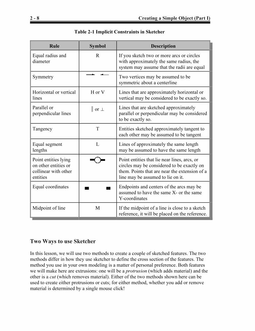
When Sketcher fires one of its internal rules (this occurs while you are sketching), you
will be alerted by a symbol on the sketch that indicates the nature of the assumed
condition. If you accept the condition, it becomes a constraint on the sketch. These
constraint symbols are summarized in Table 2-1 on the next page. You should become
familiar with these rules or constraints, and learn how to use them to your advantage. If
you do not want a rule invoked, you must either
(a) use explicit dimensions or alignments, or
(b) exaggerate the geometry so that if fired, the rule will fail, or
(c) tell Pro/E explicitly to ignore the rule (disable the constraint).
You will most often use option (a) by specifying your desired alignments and dimensions
and letting Sketcher worry about whatever else it needs to solve the sketch. When
geometry is driven by an explicit dimension, fewer internal rules will fire. Option (b) is
slightly less common. An example is if a line in a sketch must be 2E away from vertical,
you would draw it some much larger angle (like 15E or so) and put an explicit dimension
on the angle. This prevents the “vertical” rule from firing. Once the sketch has been
completed with the exaggerated angle, you can modify the dimension value to the desired
2E. For method (c), there is a command available that explicitly turns off the rule
checking (for all rules or selected ones only) during sketching. This is very rarely used.
An example of a sketch with the
geometric constraints is shown in
Figure 12. Note how few
dimensions are required to define
this sketch. See if you can pick out
the following constraints:
< vertical lines
< horizontal lines
< perpendicular lines
< tangency
< three sets of equal
length lines
< equal radius
< vertical alignment (two
cases)
How do you suppose Sketcher is
able to determine the radius of the
rounded corners (fillets) at the top
and bottom on the left edge?
Copyrighted Material
Copyrighted
Material
Copyrighted Material
Copyrighted
Material
2 - 8 Creating a Simple Object (Part I)
Table 2-1 Implicit Constraints in Sketcher
Rule Symbol Description
Equal radius and
diameter
R If you sketch two or more arcs or circles
with approximately the same radius, the
system may assume that the radii are equal
Symmetry Two vertices may be assumed to be
symmetric about a centerline
Horizontal or vertical
lines
H or V Lines that are approximately horizontal or
vertical may be considered to be exactly so.
Parallel or
perpendicular lines2 or z Lines that are sketched approximately
parallel or perpendicular may be considered
to be exactly so.
Tangency T Entities sketched approximately tangent to
each other may be assumed to be tangent
Equal segment
lengths
L Lines of approximately the same length
may be assumed to have the same length
Point entities lying
on other entities or
collinear with other
entities
Point entities that lie near lines, arcs, or
circles may be considered to be exactly on
them. Points that are near the extension of a
line may be assumed to lie on it.
Equal coordinates (( (( Endpoints and centers of the arcs may be
assumed to have the same X- or the same
Y-coordinates
Midpoint of line M If the midpoint of a line is close to a sketch
reference, it will be placed on the reference.
Two Ways to use Sketcher
In this lesson, we will use two methods to create a couple of sketched features. The two
methods differ in how they use sketcher to define the cross section of the features. The
method you use in your own modeling is a matter of personal preference. Both features
we will make here are extrusions: one will be a protrusion (which adds material) and the
other is a cut (which removes material). Either of the two methods shown here can be
used to create either protrusions or cuts; for either method, whether you add or remove
material is determined by a single mouse click!
Copyrighted Material
Copyrighted
Material
Copyrighted Material
Copyrighted
Material
Creating a Simple Object (Part I) 2 - 9
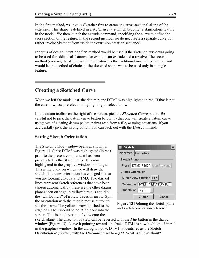
Figure 13 Defining the sketch plane
and sketch orientation reference
In the first method, we invoke Sketcher first to create the cross sectional shape of the
extrusion. This shape is defined in a sketched curve which becomes a stand-alone feature
in the model. We then launch the extrude command, specifying the curve to define the
cross section of the feature. In the second method, we do not create a separate curve but
rather invoke Sketcher from inside the extrusion creation sequence.
In terms of design intent, the first method would be used if the sketched curve was going
to be used for additional features, for example an extrude and a revolve. The second
method (creating the sketch within the feature) is the traditional mode of operation, and
would be the method of choice if the sketched shape was to be used only in a single
feature.
Creating a Sketched Curve
When we left the model last, the datum plane DTM3 was highlighted in red. If that is not
the case now, use preselection highlighting to select it now.
In the datum toolbar on the right of the screen, pick the Sketched Curve button. Be
careful not to pick the datum curve button below it - that one will create a datum curve
using sets of existing datum points, points read from a file, or using equations. If you
accidentally pick the wrong button, you can back out with the Quit command.
Setting Sketch Orientation
The Sketch dialog window opens as shown in
Figure 13. Since DTM3 was highlighted (in red)
prior to the present command, it has been
preselected as the Sketch Plane. It is now
highlighted in the graphics window in orange.
This is the plane on which we will draw the
sketch. The view orientation has changed so that
you are looking directly at DTM3. Two dashed
lines represent sketch references that have been
chosen automatically - these are the other datum
planes seen on edge. A yellow circle is actually
the “tail feathers” of a view direction arrow. Spin
the orientation with the middle mouse button to
see the arrow. The yellow arrow attached to the
edge of DTM3 should be pointing back into the
screen. This is the direction of view onto the
sketch plane. The direction of view can be reversed with the Flip button in the dialog
window (Figure 13). Leave it pointing towards the back. DTM1 is now highlighted in red
in the graphics window. In the dialog window, DTM1 is identified as the Sketch
Orientation Reference, with the Orientation set to Right. What is all this about?
Copyrighted Material
Copyrighted
Material
Copyrighted Material
Copyrighted
Material
2 - 10 Creating a Simple Object (Part I)
3Well, almost always. It is possible to sketch in 3D, in which case you can
manipulate your view so that you are not looking perpendicularly at the sketch plane.
We will not attempt that here.
The relation between the sketch plane and the sketch orientation reference
generally causes a lot of confusion for new users, so pay attention!
The meaning of the sketch plane is pretty obvious - it is the plane on which we will draw
the sketch - in this case DTM3. Our view is always perpendicular to the sketch plane3.
That is not enough by itself to define our view of the sketch since we can be looking at
that plane from an infinite number of directions (imagine the sketch plane rotating around
an axis perpendicular to the screen). The Orientation option list in the dialog window
(Top, Bottom, Left, Right) refers to directions relative to the computer screen, as in
“TOP edge of the screen” or “BOTTOM edge of the screen” and so on. We must
combine this direction with a chosen reference plane (which must be perpendicular to the
sketch plane) so that we get the desired orientation of view onto the sketching plane.
In the present case, when we get into Sketcher we will be looking directly at the brown
(positive) side of DTM3. So that the sketch is the right way up, we can choose either
DTM2 to face the Top of the screen, or (as was chosen automatically for us) DTM1 can
face the Right of the screen. Note that both DTM1 and DTM2 are both perpendicular to
the sketch plane, as required. The direction a plane or surface “faces” is determined by its
normal vector. The normal vector for a datum plane is perpendicular to the brown side.
For a solid surface, the orientation is determined by the outward normal.
Read the last couple of paragraphs again, since new users are quite liable to end up
drawing their sketches upside-down!
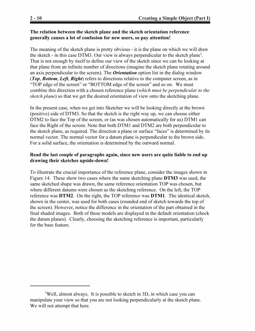
To illustrate the crucial importance of the reference plane, consider the images shown in
Figure 14. These show two cases where the same sketching plane DTM3 was used, the
same sketched shape was drawn, the same reference orientation TOP was chosen, but
where different datums were chosen as the sketching reference. On the left, the TOP
reference was DTM2. On the right, the TOP reference was DTM1. The identical sketch,
shown in the center, was used for both cases (rounded end of sketch towards the top of
the screen). However, notice the difference in the orientation of the part obtained in the
final shaded images. Both of these models are displayed in the default orientation (check
the datum planes). Clearly, choosing the sketching reference is important, particularly
for the base feature.
Copyrighted Material
Copyrighted
Material
Copyrighted Material
Copyrighted
Material
Creating a Simple Object (Part I) 2 - 11
Figure 14 The importance of the sketching reference plane!
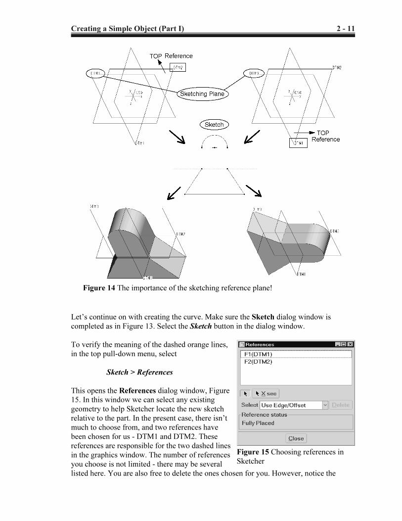
Figure 15 Choosing references in
Sketcher
Let’s continue on with creating the curve. Make sure the Sketch dialog window is
completed as in Figure 13. Select the Sketch button in the dialog window.
To verify the meaning of the dashed orange lines,
in the top pull-down menu, select
Sketch > References
This opens the References dialog window, Figure
15. In this window we can select any existing
geometry to help Sketcher locate the new sketch
relative to the part. In the present case, there isn’t
much to choose from, and two references have
been chosen for us - DTM1 and DTM2. These
references are responsible for the two dashed lines
in the graphics window. The number of references
you choose is not limited - there may be several
listed here. You are also free to delete the ones chosen for you. However, notice the
Copyrighted Material
Copyrighted
Material
Copyrighted Material
Copyrighted
Material
2 - 12 Creating a Simple Object (Part I)
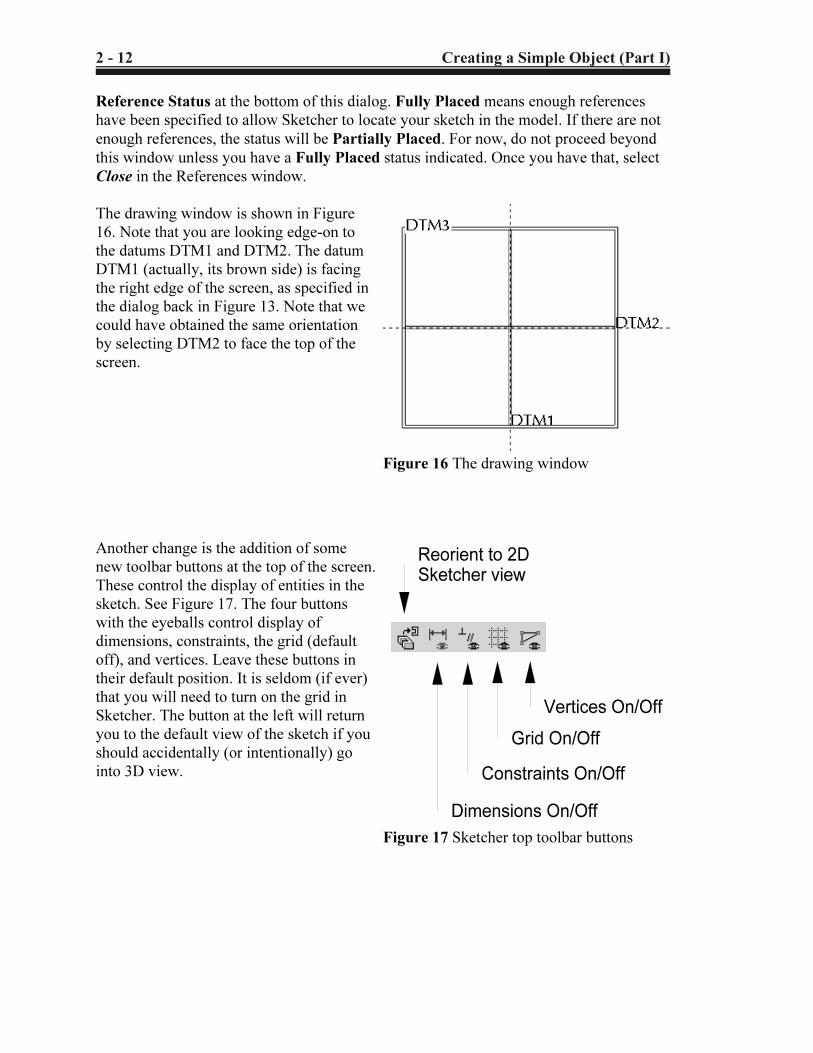
Vertices On/Off
Grid On/Off
Constraints On/Off
Dimensions On/Off
Reorient to 2D
Sketcher view
Figure 17 Sketcher top toolbar buttons
Figure 16 The drawing window
Reference Status at the bottom of this dialog. Fully Placed means enough references
have been specified to allow Sketcher to locate your sketch in the model. If there are not
enough references, the status will be Partially Placed. For now, do not proceed beyond
this window unless you have a Fully Placed status indicated. Once you have that, select
Close in the References window.
The drawing window is shown in Figure
16. Note that you are looking edge-on to
the datums DTM1 and DTM2. The datum
DTM1 (actually, its brown side) is facing
the right edge of the screen, as specified in
the dialog back in Figure 13. Note that we
could have obtained the same orientation
by selecting DTM2 to face the top of the
screen.
Another change is the addition of some
new toolbar buttons at the top of the screen.
These control the display of entities in the
sketch. See Figure 17. The four buttons
with the eyeballs control display of
dimensions, constraints, the grid (default
off), and vertices. Leave these buttons in
their default position. It is seldom (if ever)
that you will need to turn on the grid in
Sketcher. The button at the left will return
you to the default view of the sketch if you
should accidentally (or intentionally) go
into 3D view.
Copyrighted Material
Copyrighted
Material
Copyrighted Material
Copyrighted
Material
Creating a Simple Object (Part I) 2 - 13
Select
Create Line
Create Rectangle
Create Circle/Ellipse
Create Arc
Create Fillet
Create Spline
Create Point/Csys
Use Edge/Offset
Dimension
Modify
Explicit Constraints
Create Text
Trim/Divide
Move/Mirror/Rotate
Accept or Continue
QUIT
Sketch Palette
Figure 18 The Sketcher toolbar
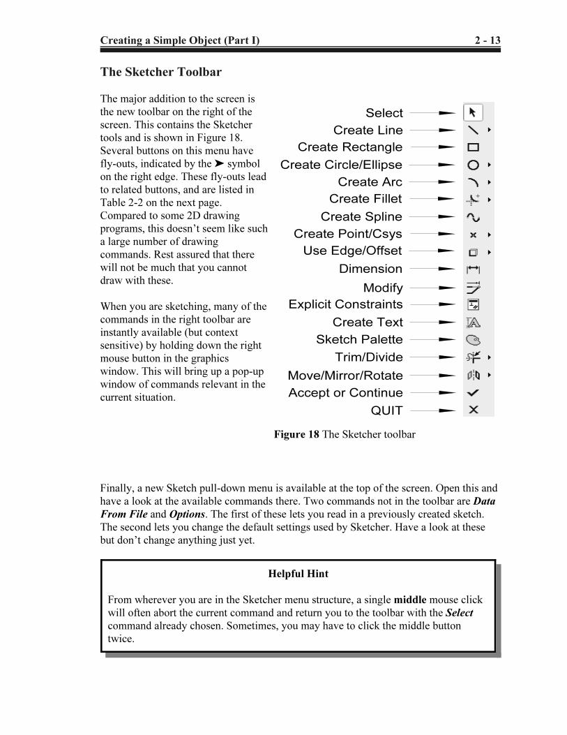
The Sketcher Toolbar
The major addition to the screen is
the new toolbar on the right of the
screen. This contains the Sketcher
tools and is shown in Figure 18.
Several buttons on this menu have
fly-outs, indicated by the ' symbol
on the right edge. These fly-outs lead
to related buttons, and are listed in
Table 2-2 on the next page.
Compared to some 2D drawing
programs, this doesn’t seem like such
a large number of drawing
commands. Rest assured that there
will not be much that you cannot
draw with these.
When you are sketching, many of the
commands in the right toolbar are
instantly available (but context
sensitive) by holding down the right
mouse button in the graphics
window. This will bring up a pop-up
window of commands relevant in the
current situation.
Finally, a new Sketch pull-down menu is available at the top of the screen. Open this and
have a look at the available commands there. Two commands not in the toolbar are Data
From File and Options. The first of these lets you read in a previously created sketch.
The second lets you change the default settings used by Sketcher. Have a look at these
but don’t change anything just yet.
Helpful Hint
From wherever you are in the Sketcher menu structure, a single middle mouse click
will often abort the current command and return you to the toolbar with the Select
command already chosen. Sometimes, you may have to click the middle button
twice.
Copyrighted Material
Copyrighted
Material
Copyrighted Material
Copyrighted
Material
2 - 14 Creating a Simple Object (Part I)
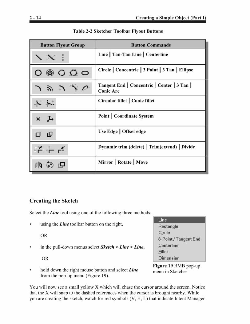
Figure 19 RMB pop-up
menu in Sketcher
Table 2-2 Sketcher Toolbar Flyout Buttons
Button Flyout Group Button Commands
Line 5 Tan-Tan Line 5 Centerline
Circle 5 Concentric 5 3 Point 5 3 Tan 5 Ellipse
Tangent End 5 Concentric 5 Center 5 3 Tan 5Conic Arc
Circular fillet 5 Conic fillet
Point 5 Coordinate System
Use Edge 5 Offset edge
Dynamic trim (delete) 5 Trim(extend) 5 Divide
Mirror 5 Rotate 5 Move
Creating the Sketch
Select the Line tool using one of the following three methods:
• using the Line toolbar button on the right,
OR
• in the pull-down menus select Sketch > Line > Line,
OR
• hold down the right mouse button and select Line
from the pop-up menu (Figure 19).
You will now see a small yellow X which will chase the cursor around the screen. Notice
that the X will snap to the dashed references when the cursor is brought nearby. While
you are creating the sketch, watch for red symbols (V, H, L) that indicate Intent Manager
Copyrighted Material
Copyrighted
Material
Copyrighted Material
Copyrighted
Material
Creating a Simple Object (Part I) 2 - 15
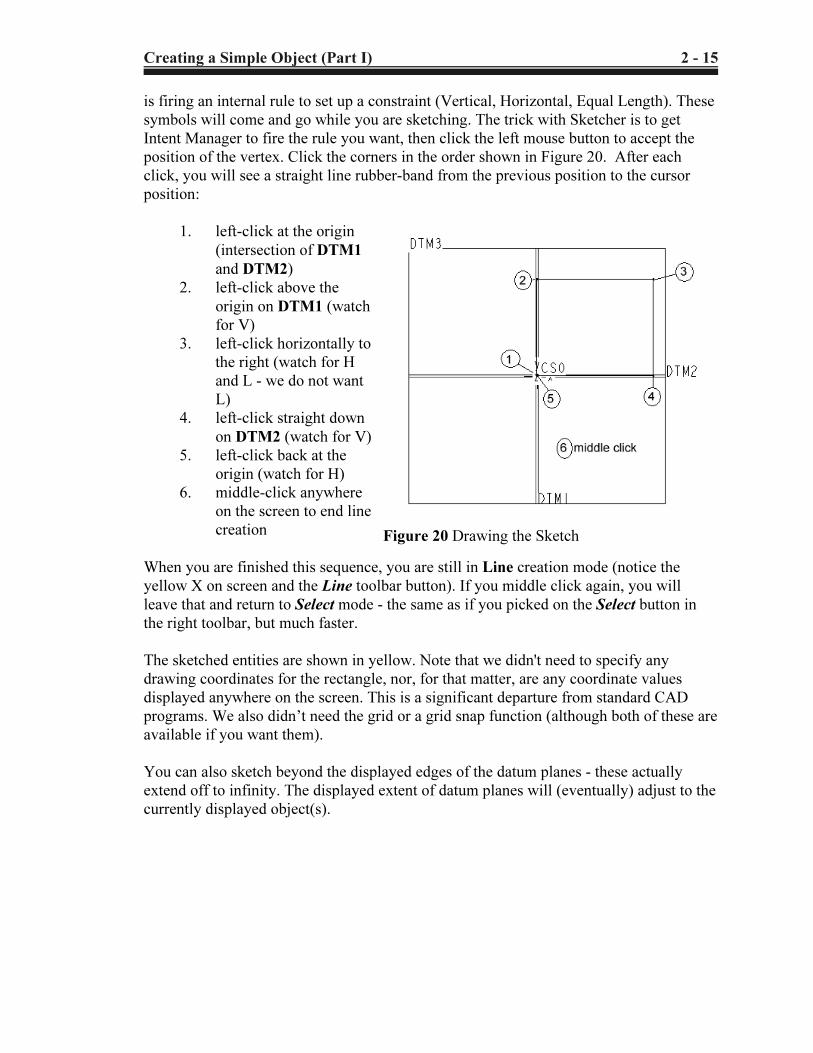
Figure 20 Drawing the Sketch
is firing an internal rule to set up a constraint (Vertical, Horizontal, Equal Length). These
symbols will come and go while you are sketching. The trick with Sketcher is to get
Intent Manager to fire the rule you want, then click the left mouse button to accept the
position of the vertex. Click the corners in the order shown in Figure 20. After each
click, you will see a straight line rubber-band from the previous position to the cursor
position:
1. left-click at the origin
(intersection of DTM1
and DTM2)
2. left-click above the
origin on DTM1 (watch
for V)
3. left-click horizontally to
the right (watch for H
and L - we do not want
L)
4. left-click straight down
on DTM2 (watch for V)
5. left-click back at the
origin (watch for H)
6. middle-click anywhere
on the screen to end line
creation
When you are finished this sequence, you are still in Line creation mode (notice the
yellow X on screen and the Line toolbar button). If you middle click again, you will
leave that and return to Select mode - the same as if you picked on the Select button in
the right toolbar, but much faster.
The sketched entities are shown in yellow. Note that we didn't need to specify any
drawing coordinates for the rectangle, nor, for that matter, are any coordinate values
displayed anywhere on the screen. This is a significant departure from standard CAD
programs. We also didn’t need the grid or a grid snap function (although both of these are
available if you want them).
You can also sketch beyond the displayed edges of the datum planes - these actually
extend off to infinity. The displayed extent of datum planes will (eventually) adjust to the
currently displayed object(s).
Copyrighted Material
Copyrighted
Material
Copyrighted Material
Copyrighted
Material
2 - 16 Creating a Simple Object (Part I)
4 The default datum display with no other features present is actually ±250 units
from where they cross.
Helpful Hints
If you make a mistake in drawing your shape, here are some ways to delete entities:
1. Pick the Select tool in the right toolbar and left click on any entity you want to
delete. Then either press the Delete key on the keyboard, or hold down the RMB and
choose Delete.
2. If there are several entities to delete, hold the CTRL key down while you left click
on each entity. Then pick Delete as before.
3. You can left-click and drag to form a rectangle around a set of entities. Anything
completely inside the rectangle is selected. Use Delete as before.
4. Notice the Undo and Redo buttons on the top toolbar
We will cover more advanced Sketcher commands for deleting and trimming lines a
bit later.
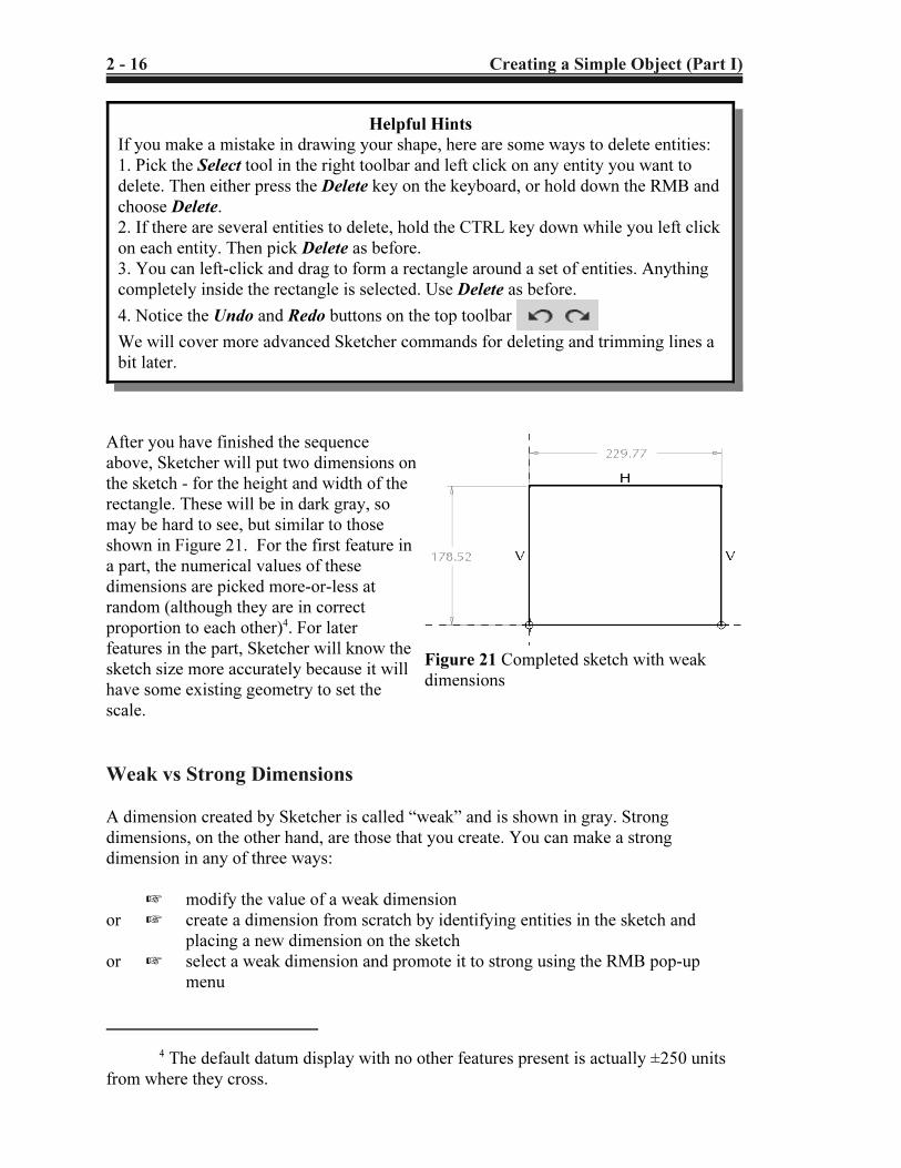
Figure 21 Completed sketch with weak
dimensions
After you have finished the sequence
above, Sketcher will put two dimensions on
the sketch - for the height and width of the
rectangle. These will be in dark gray, so
may be hard to see, but similar to those
shown in Figure 21. For the first feature in
a part, the numerical values of these
dimensions are picked more-or-less at
random (although they are in correct
proportion to each other)4. For later
features in the part, Sketcher will know the
sketch size more accurately because it will
have some existing geometry to set the
scale.
Weak vs Strong Dimensions
A dimension created by Sketcher is called “weak” and is shown in gray. Strong
dimensions, on the other hand, are those that you create. You can make a strong
dimension in any of three ways:
L modify the value of a weak dimension
or L create a dimension from scratch by identifying entities in the sketch and
placing a new dimension on the sketch
or L select a weak dimension and promote it to strong using the RMB pop-up
menu
Copyrighted Material
Copyrighted
Material
Copyrighted Material
Copyrighted
Material
Creating a Simple Object (Part I) 2 - 17
Figure 22 Modified sketch
Strong dimensions will be shown in white (actually a very pale yellow).
The special significance of weak and strong dimensions is as follows. When Intent
Manager is “solving” a sketch, it considers the sketch references, any implicit rules that
have fired (like H, V, and so on) and any existing dimensions. If there is not enough
information to define the drawing (it is underconstrained), Sketcher will create the
necessary and sufficient missing dimensions. These are the weak dimensions. If Sketcher
finds the drawing is overconstrained (too many dimensions or constraints) it will first try
to solve the sketch by deleting one or more of the weak dimensions (the ones it made
itself earlier). It will do this without asking you. This is one way for you to override
Intent Manager - if you don’t like the dimensioning scheme chosen by Sketcher, just
create your own (automatically strong) dimensions. Sketcher will remove whichever of
the weak dimensions are no longer needed to define the sketch. Sketcher assumes that
any strong dimensions you have created shouldn’t be messed with! However, if Sketcher
still finds the drawing overconstrained, it will tell you what the redundant information is
(which may be dimensions or constraints), and you can choose what you want deleted.
Thus, although weak dimensions can be deleted without asking you, Sketcher will never
delete a strong dimension without your explicit confirmation.
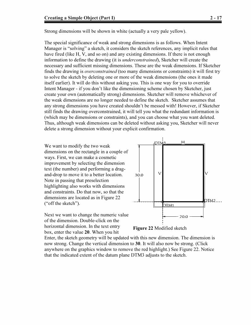
We want to modify the two weak
dimensions on the rectangle in a couple of
ways. First, we can make a cosmetic
improvement by selecting the dimension
text (the number) and performing a drag-
and-drop to move it to a better location.
Note in passing that preselection
highlighting also works with dimensions
and constraints. Do that now, so that the
dimensions are located as in Figure 22
(“off the sketch”).
Next we want to change the numeric value
of the dimension. Double-click on the
horizontal dimension. In the text entry
box, enter the value 20. When you hit
Enter, the sketch geometry will be updated with this new dimension. The dimension is
now strong. Change the vertical dimension to 30. It will also now be strong. (Click
anywhere on the graphics window to remove the red highlight.) See Figure 22. Notice
that the indicated extent of the datum plane DTM3 adjusts to the sketch.
Copyrighted Material
Copyrighted
Material
Copyrighted Material
Copyrighted
Material
2 - 18 Creating a Simple Object (Part I)
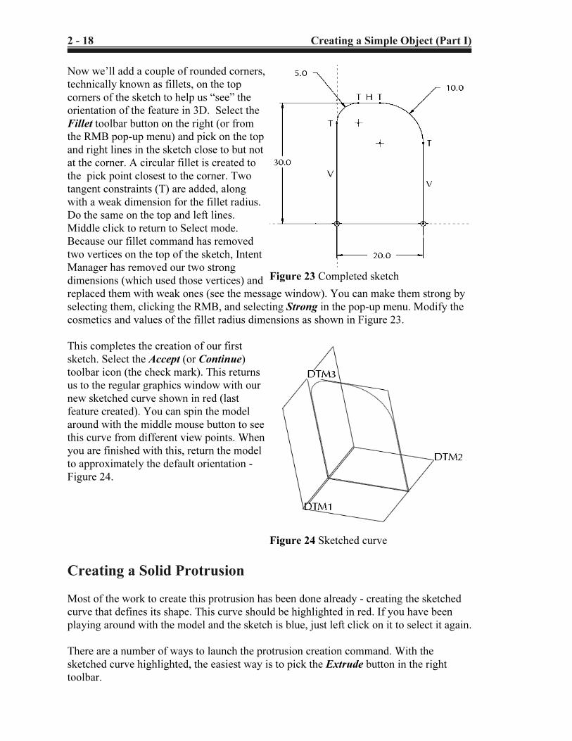
Figure 23 Completed sketch
Figure 24 Sketched curve
Now we’ll add a couple of rounded corners,
technically known as fillets, on the top
corners of the sketch to help us “see” the
orientation of the feature in 3D. Select the
Fillet toolbar button on the right (or from
the RMB pop-up menu) and pick on the top
and right lines in the sketch close to but not
at the corner. A circular fillet is created to
the pick point closest to the corner. Two
tangent constraints (T) are added, along
with a weak dimension for the fillet radius.
Do the same on the top and left lines.
Middle click to return to Select mode.
Because our fillet command has removed
two vertices on the top of the sketch, Intent
Manager has removed our two strong
dimensions (which used those vertices) and
replaced them with weak ones (see the message window). You can make them strong by
selecting them, clicking the RMB, and selecting Strong in the pop-up menu. Modify the
cosmetics and values of the fillet radius dimensions as shown in Figure 23.
This completes the creation of our first
sketch. Select the Accept (or Continue)
toolbar icon (the check mark). This returns
us to the regular graphics window with our
new sketched curve shown in red (last
feature created). You can spin the model
around with the middle mouse button to see
this curve from different view points. When
you are finished with this, return the model
to approximately the default orientation -
Figure 24.
Creating a Solid Protrusion
Most of the work to create this protrusion has been done already - creating the sketched
curve that defines its shape. This curve should be highlighted in red. If you have been
playing around with the model and the sketch is blue, just left click on it to select it again.
There are a number of ways to launch the protrusion creation command. With the
sketched curve highlighted, the easiest way is to pick the Extrude button in the right
toolbar.
Copyrighted Material
Copyrighted
Material
Copyrighted Material
Copyrighted
Material
Creating a Simple Object (Part I) 2 - 19
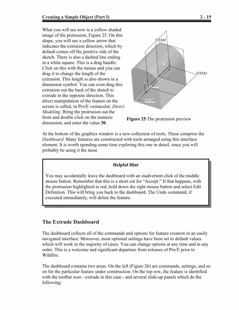
Figure 25 The protrusion preview
What you will see now is a yellow shaded
image of the protrusion, Figure 25. On this
shape, you will see a yellow arrow that
indicates the extrusion direction, which by
default comes off the positive side of the
sketch. There is also a dashed line ending
in a white square. This is a drag handle.
Click on this with the mouse and you can
drag it to change the length of the
extrusion. This length is also shown in a
dimension symbol. You can even drag this
extrusion out the back of the sketch to
extrude in the opposite direction. This
direct manipulation of the feature on the
screen is called, in Pro/E vernacular, Direct
Modeling. Bring the protrusion out the
front and double click on the numeric
dimension, and enter the value 30.
At the bottom of the graphics window is a new collection of tools. These comprise the
Dashboard. Many features are constructed with tools arranged using this interface
element. It is worth spending some time exploring this one in detail, since you will
probably be using it the most.
The Extrude Dashboard
The dashboard collects all of the commands and options for feature creation in an easily
navigated interface. Moreover, most optional settings have been set to default values
which will work in the majority of cases. You can change options at any time and in any
order. This is a welcome and significant departure from releases of Pro/E prior to
Wildfire.
The dashboard contains two areas. On the left (Figure 26) are commands, settings, and so
on for the particular feature under construction. On the top row, the feature is identified
with the toolbar icon - extrude in this case - and several slide-up panels which do the
following:
Helpful Hint
You may accidentally leave the dashboard with an inadvertent click of the middle
mouse button. Remember that this is a short cut for “Accept.” If that happens, with
the protrusion highlighted in red, hold down the right mouse button and select Edit
Definition. This will bring you back to the dashboard. The Undo command, if
executed immediately, will delete the feature.
Copyrighted Material
Copyrighted
Material
Copyrighted Material
Copyrighted
Material
2 - 20 Creating a Simple Object (Part I)
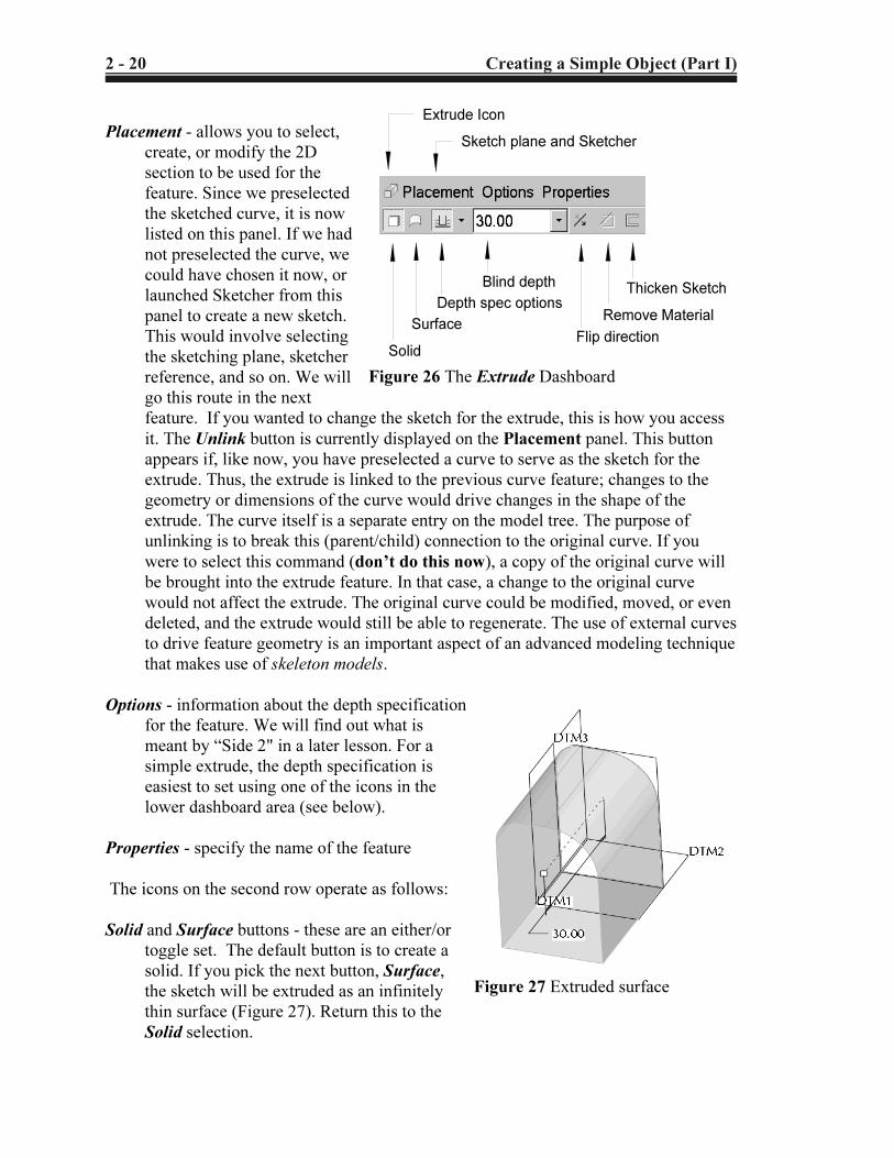
Extrude Icon
Thicken Sketch
Remove Material
Flip direction
Blind depth
Depth spec options
Surface
Solid
Sketch plane and Sketcher
Figure 26 The Extrude Dashboard
Figure 27 Extruded surface
Placement - allows you to select,
create, or modify the 2D
section to be used for the
feature. Since we preselected
the sketched curve, it is now
listed on this panel. If we had
not preselected the curve, we
could have chosen it now, or
launched Sketcher from this
panel to create a new sketch.
This would involve selecting
the sketching plane, sketcher
reference, and so on. We will
go this route in the next
feature. If you wanted to change the sketch for the extrude, this is how you access
it. The Unlink button is currently displayed on the Placement panel. This button
appears if, like now, you have preselected a curve to serve as the sketch for the
extrude. Thus, the extrude is linked to the previous curve feature; changes to the
geometry or dimensions of the curve would drive changes in the shape of the
extrude. The curve itself is a separate entry on the model tree. The purpose of
unlinking is to break this (parent/child) connection to the original curve. If you
were to select this command (don’t do this now), a copy of the original curve will
be brought into the extrude feature. In that case, a change to the original curve
would not affect the extrude. The original curve could be modified, moved, or even
deleted, and the extrude would still be able to regenerate. The use of external curves
to drive feature geometry is an important aspect of an advanced modeling technique
that makes use of skeleton models.
Options - information about the depth specification
for the feature. We will find out what is
meant by “Side 2" in a later lesson. For a
simple extrude, the depth specification is
easiest to set using one of the icons in the
lower dashboard area (see below).
Properties - specify the name of the feature
The icons on the second row operate as follows:
Solid and Surface buttons - these are an either/or
toggle set. The default button is to create a
solid. If you pick the next button, Surface,
the sketch will be extruded as an infinitely
thin surface (Figure 27). Return this to the
Solid selection.
Copyrighted Material
Copyrighted
Material
Copyrighted Material
Copyrighted
Material
Creating a Simple Object (Part I) 2 - 21
Symmetric
To Selected
Blind
Figure 28 Depth Spec
options
Figure 29 A Thick extruded solid
QUIT
Accept
View Geometry
Preview Feature
PauseCreation
Figure 30 Common
dashboard controls
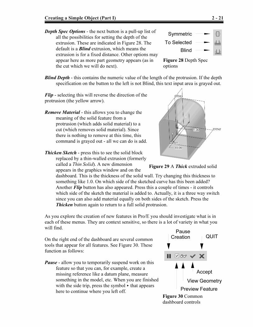
Depth Spec Options - the next button is a pull-up list of
all the possibilities for setting the depth of the
extrusion. These are indicated in Figure 28. The
default is a Blind extrusion, which means the
extrusion is for a fixed distance. Other options may
appear here as more part geometry appears (as in
the cut which we will do next).
Blind Depth - this contains the numeric value of the length of the protrusion. If the depth
specification on the button to the left is not Blind, this text input area is grayed out.
Flip - selecting this will reverse the direction of the
protrusion (the yellow arrow).
Remove Material - this allows you to change the
meaning of the solid feature from a
protrusion (which adds solid material) to a
cut (which removes solid material). Since
there is nothing to remove at this time, this
command is grayed out - all we can do is add.
Thicken Sketch - press this to see the solid block
replaced by a thin-walled extrusion (formerly
called a Thin Solid). A new dimension
appears in the graphics window and on the
dashboard. This is the thickness of the solid wall. Try changing this thickness to
something like 1.0. On which side of the sketched curve has this been added?
Another Flip button has also appeared. Press this a couple of times - it controls
which side of the sketch the material is added to. Actually, it is a three way switch
since you can also add material equally on both sides of the sketch. Press the
Thicken button again to return to a full solid protrusion.
As you explore the creation of new features in Pro/E you should investigate what is in
each of these menus. They are context sensitive, so there is a lot of variety in what you
will find.
On the right end of the dashboard are several common
tools that appear for all features. See Figure 30. These
function as follows:
Pause - allow you to temporarily suspend work on this
feature so that you can, for example, create a
missing reference like a datum plane, measure
something in the model, etc. When you are finished
with the side trip, press the symbol < that appears
here to continue where you left off.
Copyrighted Material
Copyrighted
Material
Copyrighted Material
Copyrighted
Material
2 - 22 Creating a Simple Object (Part I)
Figure 31 Completed protrusion
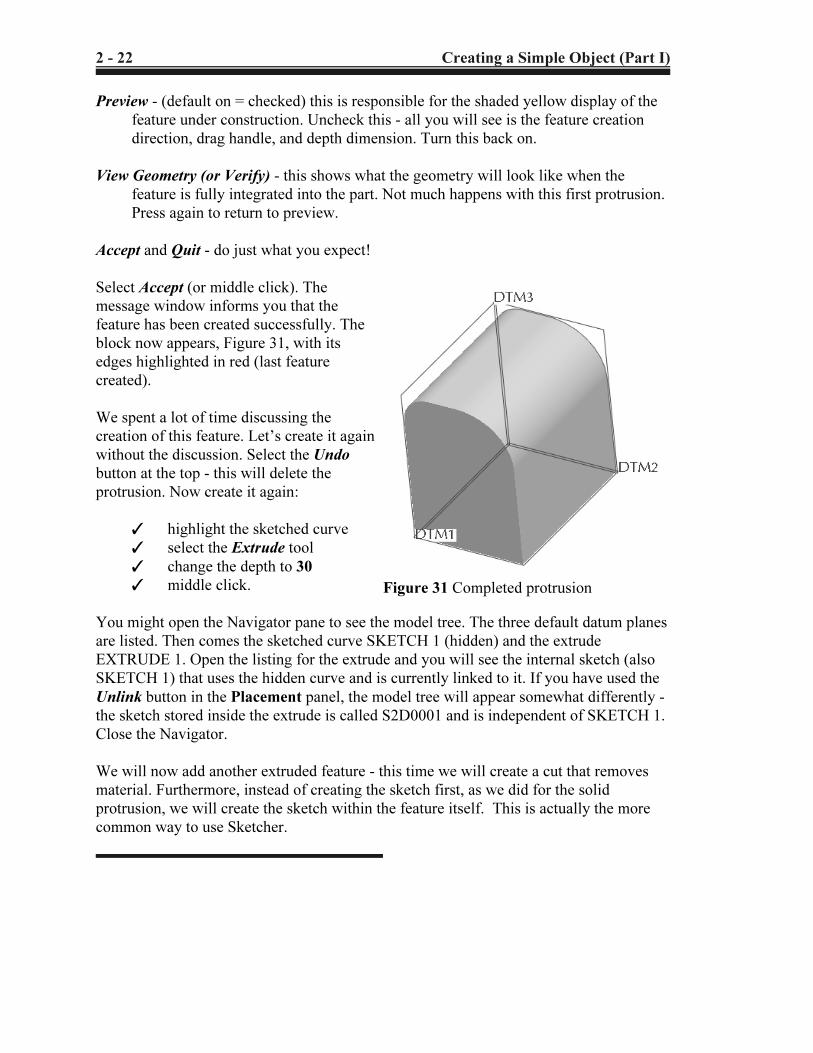
Preview - (default on = checked) this is responsible for the shaded yellow display of the
feature under construction. Uncheck this - all you will see is the feature creation
direction, drag handle, and depth dimension. Turn this back on.
View Geometry (or Verify) - this shows what the geometry will look like when the
feature is fully integrated into the part. Not much happens with this first protrusion.
Press again to return to preview.
Accept and Quit - do just what you expect!
Select Accept (or middle click). The
message window informs you that the
feature has been created successfully. The
block now appears, Figure 31, with its
edges highlighted in red (last feature
created).
We spent a lot of time discussing the
creation of this feature. Let’s create it again
without the discussion. Select the Undo
button at the top - this will delete the
protrusion. Now create it again:
T highlight the sketched curve
T select the Extrude tool
T change the depth to 30
T middle click.
You might open the Navigator pane to see the model tree. The three default datum planes
are listed. Then comes the sketched curve SKETCH 1 (hidden) and the extrude
EXTRUDE 1. Open the listing for the extrude and you will see the internal sketch (also
SKETCH 1) that uses the hidden curve and is currently linked to it. If you have used the
Unlink button in the Placement panel, the model tree will appear somewhat differently -
the sketch stored inside the extrude is called S2D0001 and is independent of SKETCH 1.
Close the Navigator.
We will now add another extruded feature - this time we will create a cut that removes
material. Furthermore, instead of creating the sketch first, as we did for the solid
protrusion, we will create the sketch within the feature itself. This is actually the more
common way to use Sketcher.
Copyrighted Material
Copyrighted
Material
Copyrighted Material
Copyrighted
Material
Creating a Simple Object (Part I) 2 - 23
SketchingPlane
SketchingReference(TOP)
Figure 32 Setting up to sketch the cut
Sketch reference
Sketch reference
Figure 33 References for cut sketch
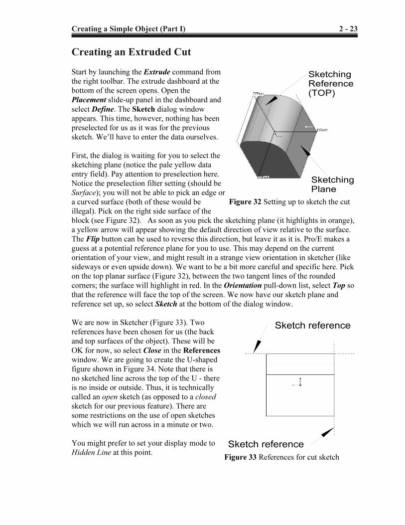
Creating an Extruded Cut
Start by launching the Extrude command from
the right toolbar. The extrude dashboard at the
bottom of the screen opens. Open the
Placement slide-up panel in the dashboard and
select Define. The Sketch dialog window
appears. This time, however, nothing has been
preselected for us as it was for the previous
sketch. We’ll have to enter the data ourselves.
First, the dialog is waiting for you to select the
sketching plane (notice the pale yellow data
entry field). Pay attention to preselection here.
Notice the preselection filter setting (should be
Surface); you will not be able to pick an edge or
a curved surface (both of these would be
illegal). Pick on the right side surface of the
block (see Figure 32). As soon as you pick the sketching plane (it highlights in orange),
a yellow arrow will appear showing the default direction of view relative to the surface.
The Flip button can be used to reverse this direction, but leave it as it is. Pro/E makes a
guess at a potential reference plane for you to use. This may depend on the current
orientation of your view, and might result in a strange view orientation in sketcher (like
sideways or even upside down). We want to be a bit more careful and specific here. Pick
on the top planar surface (Figure 32), between the two tangent lines of the rounded
corners; the surface will highlight in red. In the Orientation pull-down list, select Top so
that the reference will face the top of the screen. We now have our sketch plane and
reference set up, so select Sketch at the bottom of the dialog window.
We are now in Sketcher (Figure 33). Two
references have been chosen for us (the back
and top surfaces of the object). These will be
OK for now, so select Close in the References
window. We are going to create the U-shaped
figure shown in Figure 34. Note that there is
no sketched line across the top of the U - there
is no inside or outside. Thus, it is technically
called an open sketch (as opposed to a closed
sketch for our previous feature). There are
some restrictions on the use of open sketches
which we will run across in a minute or two.
You might prefer to set your display mode to
Hidden Line at this point.
Copyrighted Material
Copyrighted
Material
Copyrighted Material
Copyrighted
Material
2 - 24 Creating a Simple Object (Part I)
1
2 3
4
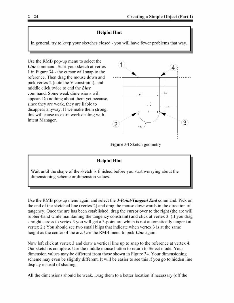
Figure 34 Sketch geometry
Use the RMB pop-up menu to select the
Line command. Start your sketch at vertex
1 in Figure 34 - the cursor will snap to the
reference. Then drag the mouse down and
pick vertex 2 (note the V constraint), and
middle click twice to end the Line
command. Some weak dimensions will
appear. Do nothing about them yet because,
since they are weak, they are liable to
disappear anyway. If we make them strong,
this will cause us extra work dealing with
Intent Manager.
Use the RMB pop-up menu again and select the 3-Point/Tangent End command. Pick on
the end of the sketched line (vertex 2) and drag the mouse downwards in the direction of
tangency. Once the arc has been established, drag the cursor over to the right (the arc will
rubber-band while maintaining the tangency constraint) and click at vertex 3. (If you drag
straight across to vertex 3 you will get a 3-point arc which is not automatically tangent at
vertex 2.) You should see two small blips that indicate when vertex 3 is at the same
height as the center of the arc. Use the RMB menu to pick Line again.
Now left click at vertex 3 and draw a vertical line up to snap to the reference at vertex 4.
Our sketch is complete. Use the middle mouse button to return to Select mode. Your
dimension values may be different from those shown in Figure 34. Your dimensioning
scheme may even be slightly different. It will be easier to see this if you go to hidden line
display instead of shading.
All the dimensions should be weak. Drag them to a better location if necessary (off the
Helpful Hint
In general, try to keep your sketches closed - you will have fewer problems that way.
Helpful Hint
Wait until the shape of the sketch is finished before you start worrying about the
dimensioning scheme or dimension values.
Copyrighted Material
Copyrighted
Material
Copyrighted Material
Copyrighted
Material
Creating a Simple Object (Part I) 2 - 25
5 This is one of the few times when a middle click does not mean “Accept”, which
is a good thing since inadvertent middle clicks happen often when you are in Sketcher.
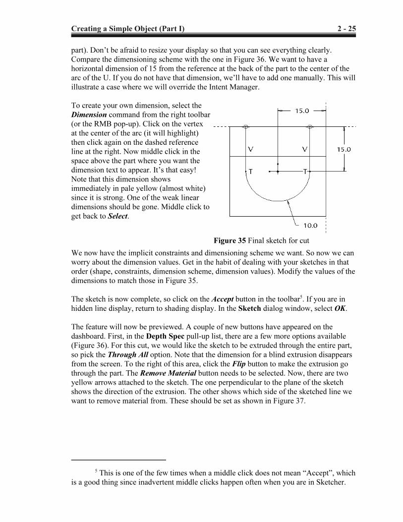
Figure 35 Final sketch for cut
part). Don’t be afraid to resize your display so that you can see everything clearly.
Compare the dimensioning scheme with the one in Figure 36. We want to have a
horizontal dimension of 15 from the reference at the back of the part to the center of the
arc of the U. If you do not have that dimension, we’ll have to add one manually. This will
illustrate a case where we will override the Intent Manager.
To create your own dimension, select the
Dimension command from the right toolbar
(or the RMB pop-up). Click on the vertex
at the center of the arc (it will highlight)
then click again on the dashed reference
line at the right. Now middle click in the
space above the part where you want the
dimension text to appear. It’s that easy!
Note that this dimension shows
immediately in pale yellow (almost white)
since it is strong. One of the weak linear
dimensions should be gone. Middle click to
get back to Select.
We now have the implicit constraints and dimensioning scheme we want. So now we can
worry about the dimension values. Get in the habit of dealing with your sketches in that
order (shape, constraints, dimension scheme, dimension values). Modify the values of the
dimensions to match those in Figure 35.
The sketch is now complete, so click on the Accept button in the toolbar5. If you are in
hidden line display, return to shading display. In the Sketch dialog window, select OK.
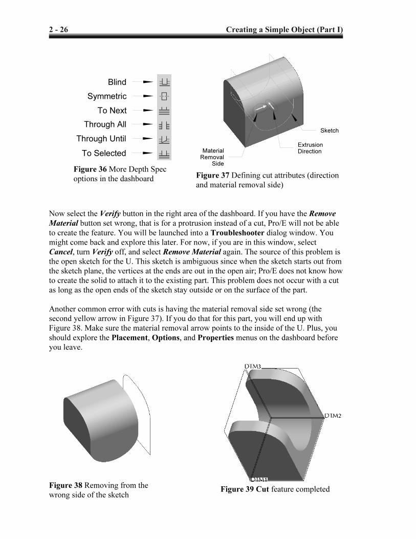
The feature will now be previewed. A couple of new buttons have appeared on the
dashboard. First, in the Depth Spec pull-up list, there are a few more options available
(Figure 36). For this cut, we would like the sketch to be extruded through the entire part,
so pick the Through All option. Note that the dimension for a blind extrusion disappears
from the screen. To the right of this area, click the Flip button to make the extrusion go
through the part. The Remove Material button needs to be selected. Now, there are two
yellow arrows attached to the sketch. The one perpendicular to the plane of the sketch
shows the direction of the extrusion. The other shows which side of the sketched line we
want to remove material from. These should be set as shown in Figure 37.
Copyrighted Material
Copyrighted
Material
Copyrighted Material
Copyrighted
Material
2 - 26 Creating a Simple Object (Part I)
Blind
Symmetric
To Next
Through All
Through Until
To Selected
Figure 36 More Depth Spec
options in the dashboard
Material
Removal
Side
Extrusion
Direction
Sketch
Figure 37 Defining cut attributes (direction
and material removal side)
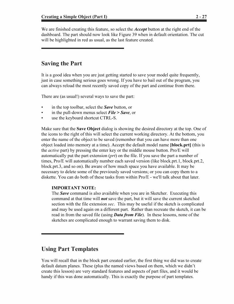
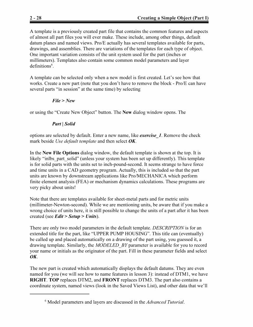
Figure 38 Removing from the
wrong side of the sketchFigure 39 Cut feature completed
Now select the Verify button in the right area of the dashboard. If you have the Remove
Material button set wrong, that is for a protrusion instead of a cut, Pro/E will not be able
to create the feature. You will be launched into a Troubleshooter dialog window. You
might come back and explore this later. For now, if you are in this window, select
Cancel, turn Verify off, and select Remove Material again. The source of this problem is
the open sketch for the U. This sketch is ambiguous since when the sketch starts out from
the sketch plane, the vertices at the ends are out in the open air; Pro/E does not know how
to create the solid to attach it to the existing part. This problem does not occur with a cut
as long as the open ends of the sketch stay outside or on the surface of the part.
Another common error with cuts is having the material removal side set wrong (the
second yellow arrow in Figure 37). If you do that for this part, you will end up with
Figure 38. Make sure the material removal arrow points to the inside of the U. Plus, you
should explore the Placement, Options, and Properties menus on the dashboard before
you leave.
Copyrighted Material
Copyrighted
Material
Copyrighted Material
Copyrighted
Material
Creating a Simple Object (Part I) 2 - 27
We are finished creating this feature, so select the Accept button at the right end of the
dashboard. The part should now look like Figure 39 when in default orientation. The cut
will be highlighted in red as usual, as the last feature created.
Saving the Part
It is a good idea when you are just getting started to save your model quite frequently,
just in case something serious goes wrong. If you have to bail out of the program, you
can always reload the most recently saved copy of the part and continue from there.
There are (as usual!) several ways to save the part:
• in the top toolbar, select the Save button, or
• in the pull-down menus select File > Save, or
• use the keyboard shortcut CTRL-S.
Make sure that the Save Object dialog is showing the desired directory at the top. One of
the icons to the right of this will select the current working directory. At the bottom, you
enter the name of the object to be saved (remember that you can have more than one
object loaded into memory at a time). Accept the default model name [block.prt] (this is
the active part) by pressing the enter key or the middle mouse button. Pro/E will
automatically put the part extension (prt) on the file. If you save the part a number of
times, Pro/E will automatically number each saved version (like block.prt.1, block.prt.2,
block.prt.3, and so on). Be aware of how much space you have available. It may be
necessary to delete some of the previously saved versions; or you can copy them to a
diskette. You can do both of these tasks from within Pro/E - we'll talk about that later.
IMPORTANT NOTE:
The Save command is also available when you are in Sketcher. Executing this
command at that time will not save the part, but it will save the current sketched
section with the file extension sec. This may be useful if the sketch is complicated
and may be used again on a different part. Rather than recreate the sketch, it can be
read in from the saved file (using Data from File). In these lessons, none of the
sketches are complicated enough to warrant saving them to disk.
Using Part Templates
You will recall that in the block part created earlier, the first thing we did was to create
default datum planes. These (plus the named views based on them, which we didn’t
create this lesson) are very standard features and aspects of part files, and it would be
handy if this was done automatically. This is exactly the purpose of part templates.
Copyrighted Material
Copyrighted
Material
Copyrighted Material
Copyrighted
Material
2 - 28 Creating a Simple Object (Part I)
6 Model parameters and layers are discussed in the Advanced Tutorial.
A template is a previously created part file that contains the common features and aspects
of almost all part files you will ever make. These include, among other things, default
datum planes and named views. Pro/E actually has several templates available for parts,
drawings, and assemblies. There are variations of the templates for each type of object.
One important variation consists of the unit system used for the part (inches or
millimeters). Templates also contain some common model parameters and layer
definitions6.
A template can be selected only when a new model is first created. Let’s see how that
works. Create a new part (note that you don’t have to remove the block - Pro/E can have
several parts “in session” at the same time) by selecting
File > New
or using the “Create New Object” button. The New dialog window opens. The
Part | Solid
options are selected by default. Enter a new name, like exercise_1. Remove the check
mark beside Use default template and then select OK.
In the New File Options dialog window, the default template is shown at the top. It is
likely “inlbs_part_solid” (unless your system has been set up differently). This template
is for solid parts with the units set to inch-pound-second. It seems strange to have force
and time units in a CAD geometry program. Actually, this is included so that the part
units are known by downstream applications like Pro/MECHANICA which perform
finite element analysis (FEA) or mechanism dynamics calculations. These programs are
very picky about units!
Note that there are templates available for sheet-metal parts and for metric units
(millimeter-Newton-second). While we are mentioning units, be aware that if you make a
wrong choice of units here, it is still possible to change the units of a part after it has been
created (see Edit > Setup > Units).
There are only two model parameters in the default template. DESCRIPTION is for an
extended title for the part, like “UPPER PUMP HOUSING”. This title can (eventually)
be called up and placed automatically on a drawing of the part using, you guessed it, a
drawing template. Similarly, the MODELED_BY parameter is available for you to record
your name or initials as the originator of the part. Fill in these parameter fields and select
OK.
The new part is created which automatically displays the default datums. They are even
named for you (we will see how to name features in lesson 3): instead of DTM1, we have
RIGHT. TOP replaces DTM2, and FRONT replaces DTM3. The part also contains a
coordinate system, named views (look in the Saved Views List), and other data that we’ll
Copyrighted Material
Copyrighted
Material
Copyrighted Material
Copyrighted
Material
Creating a Simple Object (Part I) 2 - 29
discover as we go through the lessons. The named views correspond to the standard
engineering views. Thus, it is important to note that if you are planning on using a
drawing template, your model orientation relative to the default datums is critical. The
top-front-right views of the part are the ones that will be automatically placed on the
drawing later. If your model is upside down or backwards in these named views, then
your drawing will be too. This is embarrassing and not likely to win favor with your boss
or instructor!
Now, having created this new part, you are all set up to do some of the exercises at the
end of the lesson. Do as many of these as you can. Perhaps do some of them in different
ways by experimenting with your sketch orientation, Sketcher commands, and so on.
This completes Lesson #2. You are strongly encouraged to experiment with any of the
commands that have been presented in this lesson. Create new parts for your experiments
since we will need the block part in its present form for the next lesson.
In the next lesson we will add some more features to the block, discover the magic of
relations, and spend some time learning about the utility functions available to give you
information about the model.
Copyrighted Material
Copyrighted
Material
Copyrighted Material
Copyrighted
Material
2 - 30 Creating a Simple Object (Part I)
Questions for Review
Here are some questions you should be able to answer at this time:
1. What is meant by a blind protrusion?
2. What is the purpose of the sketching reference?
3. How do you specify the name of a part?
4. Give as many of the Sketcher implicit rules as you can.
5. How do you save a part?
6. What is a template?
7. What is your system’s default template?
8. Where does your system store your part files when they are saved?
9. What is meant by the active part?
10. How does Sketcher determine the radius of a fillet created on two lines?
11. What happens if you delete any of the constraints (H, V, etc.) on a sketch?
12. In an extrude, what happens if you set the thickness of a thickened sketch greater
than the radius of a filleted corner of the sketch?
13. What is meant by Linking to a sketch?
14. In Sketcher, what is the difference between a gray and a white (pale yellow)
dimension?
15. In Sketcher, how do you create an explicit dimension?
16. In Sketcher, how do you indicate where you want the dimension text placed?
Copyrighted Material
Copyrighted
Material
Copyrighted Material
Copyrighted
Material
Creating a Simple Object (Part I) 2 - 31
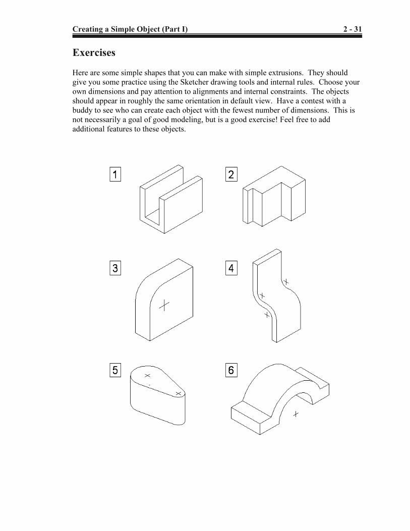
Exercises
Here are some simple shapes that you can make with simple extrusions. They should
give you some practice using the Sketcher drawing tools and internal rules. Choose your
own dimensions and pay attention to alignments and internal constraints. The objects
should appear in roughly the same orientation in default view. Have a contest with a
buddy to see who can create each object with the fewest number of dimensions. This is
not necessarily a goal of good modeling, but is a good exercise! Feel free to add
additional features to these objects.
Copyrighted Material
Copyrighted
Material
Copyrighted Material
Copyrighted
Material
2 - 32 Creating a Simple Object (Part I)
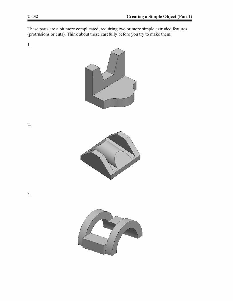
These parts are a bit more complicated, requiring two or more simple extruded features
(protrusions or cuts). Think about these carefully before you try to make them.