Phone: 0044(0)1482 221577 Fax: 0044(0)1482 325230 E-mail: [email protected]Unit 7 Salvesen way Freightliner Road Hull SatCatcher Ltd SatCatcher SatCatcher SatCatcher SatCatcher Digipro T MAX Professional Digital Terrestrial Installation Meter Detailed Operators Manual HQ ENGLISH VERSION (UK) 03.09
SatCatcherSatCatcherSatCatcherSatCatcher Digipro T MAX
Professional Digital Terrestrial
Installation Meter
Detailed Operators Manual
HQ ENGLISH VERSION (UK) 03.09
For Service Call : 0044(0)1482 221577
Page 2
Introduction to your new meter. The Digipro T Max is the latest in a range of easy to use professional Digi-tal Terrestrial installation meter’s. Please follow the easy to use instructions in this user guide to give you a perfect installation of your antenna every time. This guide is designed to be followed while using the meter .Should you need any further instruction or want to see more images, visit our website.
In the Aluminium Flight case: 1. Meter inside carry case. 2. Fold away sun visor. (Unfolded and held in place with elastic strap) Can be folded and attached to the meter bag with Velcro, for storage. 3. Software CD. 4. User guide. 5. Mains power charging unit. 6. Car charger ( power inverter option available ) 7. P.C connection cable. ( USB to USB )
Before you get Started: Section: 1 Page 3 1. Battery charging. 2. Vehicle charging. 3. Storage. 4. Care and service. 5. Safety. 6. Warranty.
Getting started Section: 2 1. Quick installation guide……………... 2. Quick Edit guide………………………… 3. Terminology………………………………. 4. Types of Installations and Tests…. 5. Function Buttons explained………... 6. Screen views explained……………… 7. Technical specification………………. 8. Editing using personal computer… 9. Help and support………………………..
Section 3 Item 10Section 3 Item 10Section 3 Item 10Section 3 Item 10 Help and support. Here at Satcatcher we are proud of our reputation for first class support and back up for all of our products. With high quality engineering and a team of dedicated professional staff , we can deliver all of our customers needs. We recommend that you search the internet or contact your local dealer, which will give you up to date information on channel lists, Frequency data and any changes that have been made around the world for all the usual transmitted channels. You can visit our website , which is updated with new channel lists regu-larly or you can email any requests you may have for us to work on for you. Our range of meters are unique in the fact that you can fully edit them by hand without having to use a PC. This gives you full flexibility in your busy working environment, were time is valuable. Our entries Plans in the meter are compiled with Current data at time of manufacture. These may change periodically and we will endeavor to update these files as quickly as possible. Terrestrial transmissons vary greatly across the world and we advise you to take local advise on channel frequencies. Please feel free to contact us with any useful comments or requests. We are here to Help you as our valued customer. www.satcatcher.com For entry list plans , updates and latest news . [email protected] For contacting us with any enquiry. 0044(0) 1482 221577 For technical enquires. Please read this manual carefully before contacting us with questions about using the meter. We can not give advise on how to make specific installations. Only technical questions about the meter which may not be covered by this manual can be discussed with our engineers by telephone. All other questions can be emailed to our team and will be answered as soon as possible. Please have your meter serial number ready with all enquiries. Your local frequency plans and transmitter data can be found online.
SERVICE TELEPHONE
To Order Call: 1 800.000.0000 For Service Call : 0044(0)1482 221577
Page 23
Satellite meter
Page 22
In the loader program you will see a column to select the Channel Band-
width (BW)
Import and Export buttons are used to move plans , between loader pro-
grams easily . Satcatcher will publish small files which can be added to
your loader and users can also send plans to each other. More details of
how to do this are on the CD you received with your meter.
You must add the bandwidth for the frequency you are adding to the plan
you are making. You can select 6 , 7 or 8 MHz for each channel. Check
you local channel bandwidths before you save your plans. Each plan can
have a maximum or 200 channels , which can be a mix of UFH/VHF
analogue or digital, FM and DAB .
Also you will need to know what PAL audio format you use in your country.
This is important when you are configuring your channel plans , as the
Video and Audio frequencies are not the same spacing's , dependent on
which country to are working in.
To Order Call: 1 800.000.0000 For Service Call : 0044(0)1482 221577
Page 3
For Service Call : 0044(0)1482 221577
Section 1 1. Battery Charging: Your new meter is supplied uncharged from manufacture and must be charged using the mains charger for an initial time of 5 hours. This will optimise the life of the battery for future use. Subsequent charges may be less. Full charge is shown on the mains charger indicator light on the mains charger housing. RED light indicates full charge. GREEN indicates charging in progress. The meter may be used for short periods of time with the mains charger attached. However we do not recommend prolonged use. The meter can be left on mains charge and will automatically shut down when it is fully charged. After the first few initial charges the batter-ies working time will be optimised. Note: Using powered switches for pro-longed periods of time will reduce the battery working time. Note: Only use genuine Satcatcher accessories supplied with your meter. 2. Vehicle Charging. You can charge the meter from the vehicle cigarette lighter outlet using the mains charger and power inverter ( if supplied ). The Vehicle charging cable can also be used if your meter is supplied with this option. 3. Storage. Your meter is supplied with a lockable aluminium flight case and foam protective inserts. We recommend that the meter is stored in this box when not in use. Keep it stored in a dry area away from sources of water. 4. Care and Service. Here at Satcatcher we care about our customers and service. We will work As fast as possible to fix any problems you may have. Service is available from many of our outlets world wide. You can purchase spare parts and have your meter serviced at any time, from dedicated professionals. 5. Safety. Please observe standard working practices when using our products. We advise that you follow all of your local health and safety regulations. 6. Warranty. Your purchase carries a 2 year return to base warranty on the meter, with one years warranty on the battery.
For Service Call : 0044(0)1482 221577
SELECT ENTRYSELECT ENTRYSELECT ENTRYSELECT ENTRY
QUICK ANTENNA TEST GUIDE
POWER ON POWER ON POWER ON POWER ON
2ND TEST 2ND TEST 2ND TEST 2ND TEST VERIFYVERIFYVERIFYVERIFY
TEST FROM TEST FROM TEST FROM TEST FROM MAIN MENUMAIN MENUMAIN MENUMAIN MENU
SELECT F1SELECT F1SELECT F1SELECT F1 MAIN MENUMAIN MENUMAIN MENUMAIN MENU
LOAD BUTTONLOAD BUTTONLOAD BUTTONLOAD BUTTON
From any of the test screens you can optimise the antenna’s signal and see the results on screen. If you need to amplify your antenna, 5v or 12v power can be added from any screen with the meter’s +/- button.
You can test any channel from your plan in each one of the 3 test screens. change the frequency on test or select /change the channel. ‘CH’ button allows you to enter a new channel number, then press ENTER to confirm. In the Digital search screen just add the channel number directly and ENTER to con-firm. The Navikey arrows up/down will scroll to the next entry in your plan in the SEARCH screen directly. DVB-T channels can be verified by viewing the TV screen or by viewing the COFDM constellation diagram. Pressing the button below the TV or QAM icon takes you directly to make these extra tests.
Getting Started : Section 2
Page 4
Scroll up or down to the entry /channel number from your pre - installed plan, then select the test method Three ways of testing are available. Scan , spectrum or search screen .Use F2 , F3 or F4 to go to the test screen you prefer.
When selecting an entry from your plan, the search screen (F4) will automatically go to the correct type of screen, either DAB, SEARCH (Analogue or Digital ) or FM test. This is dependent on the type of entry in your plan. For duplicated channel numbers you will be prompted to select analogue or digital options after you type in the Channel number.
Press the LOAD button ANY TIME to go directly to the entry list page
To Order Call: 1 800.000.0000 For Service Call : 0044(0)1482 221577
DVB DOWNLOAD SCREEN
Connect the meter and power on. With the USB cable supplied to the USB port of your computer. Click COM TEST on the loader and the program will select the correct USB port configured previously on your P.C . On the meter’s keypad press F1 to go to the main menu and then press key button number 8. Your Meter will now display the message, CONNECT TO COMPUTER. All of the plans to download are displayed on the left of above screen. Note : A maximum of 15 plans , with total entries not exceeding 500 can be downloaded to the meter. Next , click the START DOWNLOAD BUTTON on the loader and wait for prompts on the meter and the loader program to confirm that the process has finished. If connection is not established then try again, first selecting a different com port , check your P.C. port settings. Com port 1—16 are available for use as the virtual port in DEVICE manager . Full instructions in detail can be found on the CD provided with your meter.
Page 21
Using the loader program CONFIGURATION SCREEN
You will need to know your local settings for correctly adding channel data to any new plans . This can be found at your local dealer or via the internet. The process for adding plans is simple. First choose an empty plan/group from the 200 which are listed on the left side of your screen. Click ADD CHANNEL, then enter the data for the channel . Select channel type 1st. TYPE : This can be Analogue, Digital , FM or DAB CH : Is channel number, of the frequency you are adding . NAME : You can choose any name you wish. VIDEO : Add the video frequency number of the channel in MHz. AUDIO : Add the audio frequency number of the channel in MHz. DIGITAL : This is the Digital frequency in MHz BW : This is the channel bandwidth, select 6, 7 or 8 MHz After entering the details click OK and the channel will be added to the plan. Repeat this procedure for all of the channels you wish to add .If you want to download multiple plans , Click on a plan on the left side , then click ADD to Download . Repeat this for each plan you want to send and then proceed to the next screen “DVB DOWNLOAD” , which can be found at the top left side of the loader program screen.
Page 20
To Order Call: 1 800.000.0000 For Service Call : 0044(0)1482 221577
F1 MAIN MENUF1 MAIN MENUF1 MAIN MENUF1 MAIN MENU
QUICK EDIT GUIDE
POWER ON POWER ON POWER ON POWER ON
F3 TO SAVE F3 TO SAVE F3 TO SAVE F3 TO SAVE
EXIT EXIT EXIT EXIT
EDIT DETAILSEDIT DETAILSEDIT DETAILSEDIT DETAILS
EDIT/ADDEDIT/ADDEDIT/ADDEDIT/ADD
From the main menu, use the NAVIKEY left/right arrow to high-light Icon 5 (ABC/123 )then press F4. Or you can press the number 5 button on the keypad from the main menu directly to enter into this screen.
After saving the edit or new entry , press EXIT (F4) repeatedly until you return to the main menu .Or press one of the short cut keys to go directly to a test screen. From the main menu , proceed to the next test or press LOAD to go di-rectly to the plan entry list that is currently in use.
For Service Call : 0044(0)1482 221577
Page 5
In this menu, use the NAVIKEY up/down arrow to select item 2 edit plan. Press F4 (OK) to enter , now you can see the current plan entries which can be edited by scrolling to the entry and pressing the F4 (OK) button.
In this menu, edit the parameters you need by selecting with the ENTER button. Use the numbers and letter buttons on the keypad to add text. The TYPE of entry is changed by pressing the ENTER button repeatedly to display DAB , FM, ANALOGUE and DIGITAL.
For Service Call : 0044(0)1482 221577
Page 6
Section 2 Item 3 Terminology For any new user to Terrestrial meter’s this section gives a brief descrip-tion of some of the words and terms used , It explains the terms in an easy to understand format and tries not to be so technical. For a more technical understanding , we advise you to search for the words on the internet. CBER — PRE (CHANNEL BIT ERROR RATE) This is the amount of errors in the bits of information, before any device has corrected these errors. You will need to have largest Number after the ‘E’ to have the best signal. VBER — POST (VITERBI ERROR RATE) This is the amount of errors in the bits of information after the errors have been corrected by the receiving device. These are corrected by the Meter or the Set top box used. You will need to have largest Number after the ‘E’ to have the best signal. LEVEL .This is the actual complete signal that is being received. COFDM (Coded Orthogonal frequency Division Multiplexing) The modula-tion scheme used for digital terrestrial signal transmitting. Signals are sent in various formats as seen below in the QAM explanation. QAM. (Quadrature amplitude modulation) A way in which some digital signals are transmitted. 16 QAM and 64 QAM are used for digital TV .You can interrogate the parts of this signal with the COFDM/QAM test function. The tighter together the constellation diagrams (small dots that refresh on the screen) the cleaner the signal. One part or multiple parts of the quadrant may have errors which you can view. MER ( modulation error ratio ) This measurement is a calculation of the amount of errors present in a digital signal. The higher this value , the less corruption in the signal. Over 25 dB MER is an acceptable level, but must considered along with good CBER,C/N and VBER readings. POWER LEVEL .( DIGITAL POWER ) This is the averaged power of the in-coming signal. Shown in the search screen as large numbers in the centre of the screen. The higher the number , the stronger the signal. C/N (CARRIER TO NOISE RATIO) This represents a calculation of back-ground dirty signal (noise) against the good incoming signals. Aim for the highest figure of C/N to have the best quality signal.
Page 19
Section 2 Item 8 Section 2 Item 8 Section 2 Item 8 Section 2 Item 8 Editing using personal computer Your new meter is supplied with a software CD which contains a loader program which can communicate via a USB connection port on your P.C to the full USB port on the meter. It is important that you install the program on your P.C before you connect the meter to your computer. The install will set up the port as a com port in Device manager on your P.C. You can go into Device manager and change the port number if you wish. Please refer to instructions in the readme file on the CD Provided. Insert the CD into the CD/DVD drive on you P.C and follow this procedure: On your P.C Click START - MY COMPUTER - Click on the correct drive for which the CD is loaded. Double Click on the Icon TMAX and you will see the installation screen appear. Select a location to add the program and follow the on screen prompts to install the program. After installation is complete , you will see an Icon appear on your desktop , which you can use to access the loader program. The TMAX loader is designed to allow you to edit, add and delete channel plans for download to your meter. Your meter’s internal memory can store 15 channels plans , with a total number of 500 individual entries.(200 max per plan) This means you can have many channels added in one plan , or less channels in multiple plans. Each plan can be named as you wish, with any type of entry being available in each plan. For example : Plan 1 , you may wish to enter Analogue, FM , DAB and Digital entries of your local transmitter, with Plan 2 being a plan of the full frequency range of the channels (21—69 ) with both Analogue and Digital entries present . You can use the same channel number more than once , as the meter will prompt you to select which type of you channel you need to test. There are two screens in the Loader program. Screen 1 is the configuration screen , which is used to edit current plans , delete channels or plans and for adding new channel data to new plans you wish to add. You can also import and export plans from this screen. Screen 2 is the Download screen , which is were you select which plans you want inside the meter before you connect and add them. Pictures of the two screens can be seen overleaf. IMPORTANT NOTE : When downloading new plans to your meter, do not disconnect your Meter or PC until you see the COMPLETE message on both devices.
To Order Call: 1 800.000.0000 For Service Call : 0044(0)1482 221577
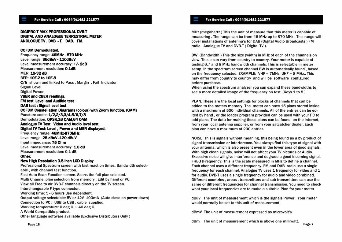
DIGIPRO T MAX PROFESSIONAL DVBDIGIPRO T MAX PROFESSIONAL DVBDIGIPRO T MAX PROFESSIONAL DVBDIGIPRO T MAX PROFESSIONAL DVB----T T T T DIGITAL AND ANALOGUE TERRESTRIAL METERDIGITAL AND ANALOGUE TERRESTRIAL METERDIGITAL AND ANALOGUE TERRESTRIAL METERDIGITAL AND ANALOGUE TERRESTRIAL METER ANOLOGUE TV . DVB ANOLOGUE TV . DVB ANOLOGUE TV . DVB ANOLOGUE TV . DVB ---- T.T.T.T. DAB.DAB.DAB.DAB. FM.FM.FM.FM. COFDM Demodulated.COFDM Demodulated.COFDM Demodulated.COFDM Demodulated. Frequency range: 46MHz 46MHz 46MHz 46MHz ---- 870 MHz870 MHz870 MHz870 MHz Level range: 35dBuV 35dBuV 35dBuV 35dBuV ---- 110dBuV110dBuV110dBuV110dBuV Level measurement accuracy: +/+/+/+/---- 2dB2dB2dB2dB Measurement resolution: 0.1dB0.1dB0.1dB0.1dB MER: 19191919----32 dB32 dB32 dB32 dB BER: 10E10E10E10E----2 to 10E2 to 10E2 to 10E2 to 10E----8888 C/N C/N C/N C/N shown and linked to Pass , Margin , Fail Indicator. Signal Level Digital Power VBER and CBER readings.VBER and CBER readings.VBER and CBER readings.VBER and CBER readings. FM test: Level and Audible testFM test: Level and Audible testFM test: Level and Audible testFM test: Level and Audible test DAB test : Signal level testDAB test : Signal level testDAB test : Signal level testDAB test : Signal level test COFDM Constellation Diagrams (colour) with Zoom function. (QAM)COFDM Constellation Diagrams (colour) with Zoom function. (QAM)COFDM Constellation Diagrams (colour) with Zoom function. (QAM)COFDM Constellation Diagrams (colour) with Zoom function. (QAM) Puncture codes:1/2,2/3,3/4,5/6,7/81/2,2/3,3/4,5/6,7/81/2,2/3,3/4,5/6,7/81/2,2/3,3/4,5/6,7/8 Demodulation: QPSK,16 QAM,64 QAMQPSK,16 QAM,64 QAMQPSK,16 QAM,64 QAMQPSK,16 QAM,64 QAM Analogue TV Test : Video and Audio level test. Analogue TV Test : Video and Audio level test. Analogue TV Test : Video and Audio level test. Analogue TV Test : Video and Audio level test. Digital TV Test: Level , Power and MER displayed.Digital TV Test: Level , Power and MER displayed.Digital TV Test: Level , Power and MER displayed.Digital TV Test: Level , Power and MER displayed. Frequency range: 46MHz46MHz46MHz46MHz----870MHz870MHz870MHz870MHz Level range: 25 dBuV 25 dBuV 25 dBuV 25 dBuV ----120 dBuV120 dBuV120 dBuV120 dBuV Input impedance: 75 Ohm75 Ohm75 Ohm75 Ohm Level measurement accuracy: 1.0 dB1.0 dB1.0 dB1.0 dB Measurement resolution: 0.1 dB Other:Other:Other:Other: New High ResolutionNew High ResolutionNew High ResolutionNew High Resolution 3.5 inch LCD Display3.5 inch LCD Display3.5 inch LCD Display3.5 inch LCD Display Professional Spectrum screen with fast reaction times. Bandwidth select-able , with channel test function. Fast Auto Scan Function screen. Scans the full plan selected. Multi Channel plan selection from memory . Edit by hand or PC. View all Free to air DVB-T channels directly on the TV screen. Interchangeable F type connector. Working time: 5 - 6 hours Use dependent. Output voltage selectable: 5V or 12V -100mA (Auto close on power down) Connection to PC : USB to USB , cable supplied. Working temperature: 0 deg C. ~ 40 deg C. A World Compatible product. Other language software available (Exclusive Distributors Only )
To Order Call: 1 800.000.0000 For Service Call : 0044(0)1482 221577
Page 18 Page 7
For Service Call : 0044(0)1482 221577
MHz (megahertz ) This the unit of measure that this meter is capable of measuring . The range can be from 46 MHz up to 870 MHz . This range will cover installations of antenna’s for DAB (Digital Audio Broadcasts ) FM radio , Analogue TV and DVB-T ( Digital TV ). BW (Bandwidth ) This the size (width) in MHz of each of the channels on view. These can vary from country to country. Your meter is capable of testing 6,7 and 8 MHz bandwidth channels. This is selectable in meter setup. In the spectrum screen channel BW is automatically found , based on the frequency selected. EXAMPLE: VHF = 7MHz UHF = 8 MHz.. This may differ from country to country and will be software configured before purchase. When using the spectrum analyzer you can expand these bandwidths to see a more detailed image of the frequency on test. (Keys 1 to 8 ) PLAN. These are the local settings for blocks of channels that can be added to the meters memory. The meter can have 15 plans stored inside with a maximum of 500 individual channels. All of the entries can be ed-ited by hand , or the loader program provided can be used with your PC to add plans. The data for making these plans can be found on the internet, from your local antenna supplier, or from your satcatcher dealer. Each plan can have a maximum of 200 entries. NOISE. This is signals without meaning, this being found as a by product of signal transmission or interference. You always find this type of signal with your antenna, which is also present even in the lower area of good signals. With high clean signals, noise will not affect your TV pictures or Audio. Excessive noise will give interference and degrade a good incoming signal. FREQ (Frequency) This is the scale measured in MHz to define a channel. Each channel uses a different frequency. FM and DAB radio use a single frequency for each channel. Analogue TV uses 1 frequency for video and 1 for audio. DVB-T uses a single frequency for audio and video combined. Different countries , areas , transmitters and sub transmitters can use the same or different frequencies for channel transmission. You need to check what your local frequencies are to make a suitable Plan for your meter. dBuV . The unit of measurement which is the signals Power . Your meter would normally be set to this unit of measurement. dBmV The unit of measurement expressed as microvolt's. dBm The unit of measurement which is above one milliwatt.
To Order Call: 1 800.000.0000
AMPLIFIER (MAST HEAD) This electronic device is added generally on the mast to which the antenna is fitted. It adds extra power to the incoming signal, in areas of weak signal or areas with other signal power problems. This is fitted in line on the coax-ial cable from the antenna , normally a maximum of about one meter from the antenna. These devices require 5 volts or 12 volts or a variable 5-12 volts to work correctly. Power is provided by the set top box or a sepa-rate power supply unit. Your meter can supply 5 Volts or 12 Volts for testing your installation. In all screens repeatedly pressing the +/- key of the meter ,adds the voltage required. Powering down the meter , removes the voltage from the test and needs to be selected again if required , when the meter is next powered on.
Test Values Explained: The CBER (Channel Bit Error Rate) gives you an idea of the quality of the signal. Depending on its value you can tell how good your reception is: - CBER <= E-4: this is optimal and you can feel confident with the quality of the signal. - CBER = E-03: is slightly low and will decrease more when it starts to rain heavily. Either the antenna type used is wrong, the area is bad for reception or the antenna is incorrectly positioned - CBER >= E-02: is too weak to give a clear uninterrupted TV picture. The VBER (Viterbi Bit Error Rate) which is the error rate after correction. This with a high CBER result will give a signal reading < E-08 , this is the highest value. The LEVEL, is shown as the BAR on the main screen. It is easy to see this move up and down as you move the antenna. When it is at its highest point ,then you can check the other results in the search screen. The C/N is shown in the search screen and is linked to the Pass, Margin and Fail results. In the top right hand side of the search screen you will see a P , M or F letter to indicate the status of your test. This is an indicator only and we recommend you read all the results to determine if the signal is acceptable. You can set C/N levels in the setup menu to suite yours requirements. The V and A (Video and Audio levels for analogue) shows the two levels. Under this you can see the amount of the difference between Audio and Video signal. This figure needs to be as low as possible , to avoid high
audio level interference to the Analogue video pictures.
For Service Call : 0044(0)1482 221577
Page 8
TV SCREEN. This screen will allow you to view the TV channels from the selected entry used for the installation. This is only possible with free to air Digital DVB-T channels, so please check the frequency used is not encrypted in any way . When this screen is selected, a notice will appear on screen to inform you that the meter is searching and downloading the available channels. The first of the channels will appear on screen, so you can view the picture and check the picture for its quality and stability. Using the NAVIKEY up/down buttons , you can move to the next channel if any other channels are present. The NAVIKEY left /right buttons will control the volume when in this screen. To exit this screen press the F4 button from the keypad. ON SCREEN MESSAGES EXPLAINED : (WARNING! SHORT CHECK 12V. )This message will appear if you have selected 5v or 12v with the +/- key, without any amplifier present. The me-ter will automatically shut down to protect itself. Switch the meter back on and the voltage will be reset to zero voltage automatically. BATTERY INDICATOR This can be seen at the top of each screen and shows the status of the battery power. SAME CHANNEL NUMBER SELECTION. The full frequency plan is pre-installed in the meter , with the full frequency band listed with both Analogue and Digital channel numbers in UFH /VHF. In the full frequency plan (if installed) , you will see the same channel num-ber may be added for both Analogue and Digital channels. In all the test screens, when you select a duel entered channel number , you will see a prompt box appear on the screen , to be able to select either Analogue or Digital to test. Pressing F1 or F2 will select the correct channel as detailed in the prompt box. You can only add two channels with the same number into your plans. If you try to add a third channel with the same number, you will see an error message on screen. SHORTCUT KEYS. The right hand buttons on the keypad can be used to quickly to access any of the test screens. See page 12 for details.
To Order Call: 1 800.000.0000 For Service Call : 0044(0)1482 221577
Page 17
To Order Call: 1 800.000.0000 For Service Call : 0044(0)1482 221577
CBER: CBER: CBER: CBER: 2.3 E 32.3 E 32.3 E 32.3 E 3 VBER: VBER: VBER: VBER: <1.0 E 7<1.0 E 7<1.0 E 7<1.0 E 7 MER: MER: MER: MER: 24.0 dB24.0 dB24.0 dB24.0 dB
Screen shots of test methods that are available. Page 9
Section 2 Item 4 Types of Installation - FM radio
Types of Installation - DAB radio
To Order Call: 1 800.000.0000 For Service Call : 0044(0)1482 221577
SELECT FM SELECT FM SELECT FM SELECT FM CHANNELCHANNELCHANNELCHANNEL
POWER ON POWER ON POWER ON POWER ON
Press F4Press F4Press F4Press F4 TO EXIT TO EXIT TO EXIT TO EXIT
Use the NAVIKEY arrows up/down to scroll to the correct FM entry in the list . Press F4 button to go directly to the FM test screen. Move the antenna to see the highest value in the level box Press F1 to turn the volume on and F2 to adjust the volume. You can now hear the radio station selected. You can also access the FM test screen from the main menu, were you can add the frequency you want to test .
SELECT DABSELECT DABSELECT DABSELECT DAB CHANNELCHANNELCHANNELCHANNEL
POWER ON POWER ON POWER ON POWER ON
Press F4Press F4Press F4Press F4 TO EXIT TO EXIT TO EXIT TO EXIT
Use the NAVIKEY arrows up/down to scroll to the correct DAB entry in the list . Press F4 button to go directly to the DAB test screen. Move the antenna to see the highest value in the level box. You can also access the DAB test screen from the main menu, were you can add the frequency you want to test.
Page 10
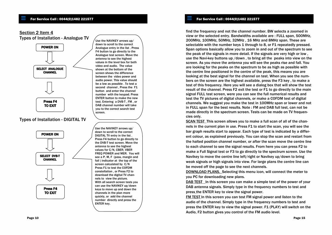
Section 2 Item 4 Types of Installation - Analogue TV
Types of Installation - DIGITAL TV
To Order Call: 1 800.000.0000 For Service Call : 0044(0)1482 221577
Press F4Press F4Press F4Press F4 TO EXIT TO EXIT TO EXIT TO EXIT
Use the NAVIKEY arrows up/down to scroll to the correct Analogue entry in the list . Press F4 button to go directly to the Analogue test screen. Move the antenna to see the highest values in the level box for both video and audio. The value shown at the bottom of the screen shows the difference between the video power and audio power. This value should be a low as possible . To test a second channel , Press the F1 button and enter the channel number with the keypad. Press ENTER button to make the new test. Entering a DVB-T , FM , or DAB channel number will take you to the correct search test screen.
Use the NAVIKEY arrows up/down to scroll to the correct DIGITAL TV entry in the list . Press F4 button to go directly to the DVB-T test screen. Move the antenna to see the highest values for C/N, CBER, VBER FREQ POWER and MER. You will see a P, M, F (pass, margin and fail ) indicator at the top of the screen calculated by C/N Press F1 to test the COFDM constellation , or Press F2 to download the digital TV chan-nels to view the picture. With all search screen tests you can use the NAVIKEY up/down keys to move up and down the channels in the plan more quickly, or add the channel number directly and press the ENTER key.
find the frequency and not the channel number. BW selects a zoomed in view or the selected entry. Bandwidths available are : FULL span, 500MHz, 200MHz, 100MHz, 50MHz, 32MHz , 16 MHz and 8MHz span. These are selectable with the number keys 1 through to 8, or F1 repeatedly pressed. Span options basically allow you to zoom in and out of the spectrum to see the peak of the signals in more detail. If the signals are very high or low , use the Navi-key buttons up /down , to bring all the peaks into view on the screen. As you move the antenna you will see the peaks rise and fall. You are looking for the peaks on the spectrum to be as high as possible with the centre line positioned in the centre of the peak, this means you are looking at the best signal for the channel on test. When you see the num-bers on the screen are the highest available, press the F3 key , to make a test of this frequency. Here you will see a dialog box that will show the test result of the channel. Press F2 exit the test or F1 to go directly to the main signal FULL test screen, were you can see the full numerical results and test the TV pictures of digital channels, or make a COFDM test of digital channels. We suggest you make the test in 100MHz span or lower and not in FULL span for the best results. Note : FM and DAB full test, can not be made directly in the spectrum screen. Tests can be made on TV frequen-cies only.
SCAN TEST This screen allows you to make a full scan of all of the chan-
nels in the current plan in use. Press F1 to start the scan, you will see the
bar graph results start to appear. Each type of test is indicated by a differ-
ent colour, as explained previously. You can stop the scan and restart from
the halted position channel number, or after the scan move the centre line
to each channel to see the signal results. From here you can press F2 to
make a Full Signal test or F3 to go directly to the spectrum screen. Use the
Navikey to move the centre line left/right or Navikey up/down to bring
weak signals or high signals into view. For large plans the centre line can
be moved off the page to see the next channels.
DOWNLOAD PLANS. Selecting this menu icon, will connect the meter to
you PC for downloading new plans.
DAB TEST In this screen you can make a simple test of the power of your
DAB antenna signals. Simply type in the frequency numbers to test and
press the ENTER key to view the signal power.
FM TEST In this screen you can test FM signal power and listen to the
audio of the channel. Simply type in the frequency numbers to test and
press the ENTER key to view the signal power. F1 (PLAY) will switch on the
Audio, F2 button gives you control of the FM audio level.
To Order Call: 1 800.000.0000 For Service Call : 0044(0)1482 221577
Page 15
Section 2 item 6
Screen views explained. Main menu screens.
The main menu screen is displayed by pressing the F1 button after power
on. Press the number on the keypad of the screen you want to enter or use
the Navi-key buttons to highlight a screen and press the F4 button to
select the screen to enter. Direct entry is available using keys 1 to 8.
EDIT/ADD PLANS. When you select this menu screen you will see 2
options . (1) is select plan, from here you can select a new plan to add into
the meter from the main memory . (2) is selected to edit the entries in the
current plan that is in use in the sub memory.
METER SETUP. When in this screen you will see various parameters which
are editable by the user. Set each line to what suits your needs and exit
the menu. In this menu you have options to change: Bandwidth, set pass
and fail levels, auto shutdown time for the meter and the unit of measure
you want to use to make the tests. Pass, Margin and Fail is C/N value.
SIGNAL TEST. SEARCH This screen is the quick way to test all the channels.
In here you can scroll through the current plan to select a channel, or add
the channel number directly to start a test. Press F1 to edit the channel
number , then press ENTER to see the results. Use the Navikey up/down to
scroll through the current channel plan that is in use. Pass Margin and Fail
results are indicated on screen as P M and F letters. The parameter’s for
these can be set in the meter set-up menu, calculated from C/N figures.
SPECTRUM TEST. Selecting this Icon will take you directly to the spectrum
screen. Here you can see the full frequency range, or by changing the BW
see more detail of each channel or frequency. Press F1 ,press the numbers
of the channel you want to add then ENTER. Example : 25 then ENTER. If
you have two channels with the same number you will be prompted to se-
lect Analogue or Digital. To add a frequency, add the frequency number in
the channel number box, including the decimal places to two points.
Example : 475. 25 or 457.00 .The ( . ) tells the meter to
To Order Call: 1 800.000.0000 For Service Call : 0044(0)1482 221577
SCAN TEST 2
SIGNAL TEST SEARCH
1
METER SETUP 4
FM TEST 6
EDIT/ADD PLANS
5
SPECTRUM TEST 3
DAB TEST 7
DOWNLOAD PLANS
8
Page 14
Section 2 Item 4 Types of Test - SPECTRUM - SCAN - SEARCH Your new meter allows you to make 3 different test methods . You can add 5v or 12v to any installation in which you are us-ing powered amplification devices with the above voltage re-quirement . Add or remove voltage using the +/- button on the meter’s keypad. Voltage settings are auto cancelled when the meter is powered down. Spectrum Testing: The spectrum Analyzer in your meter allows you to see the full frequency band in one screen. You can view each frequency in detail, by changing the bandwidth to effectively zoom in to the profile of the channel, to check for its shape and quality. You can see the level of each channel, Go to the centre of each channel or move the centre line to the profile peak to test. You can also make a full test of the frequency selected, with the press of a single button. Scan Testing: The scan function shows a bar graph of the full plan you are using. By starting the scan function , your meter looks at each entry in turn and displays the results in different colours which denotes the type of signal. The centre line can be moved to see the power of each channel, using the Navikey left/right button. The line can move off the screen to reveal the next re-sults when the screen is full. F2 button takes you to the full correct test screen, to see test results. Yellow = Analogue video Blue behind yellow = Analogue audio White (Transparent ) with black outline = Digital TV Black = DAB radio Green = FM radio Search Testing: This function allows you to view all of the numerical results of a channel test in one screen. You can quickly move to the next test , by entering the channel number of moving through the list with the Navikey up/down button.
To Order Call: 1 800.000.0000 For Service Call : 0044(0)1482 221577
Page 11
Page 12
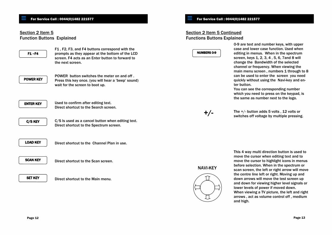
Section 2 Item 5 Function Buttons Explained
To Order Call: 1 800.000.0000 For Service Call : 0044(0)1482 221577
F1 F1 F1 F1 ––––F4F4F4F4
LOAD KEY LOAD KEY LOAD KEY LOAD KEY
ENTER KEYENTER KEYENTER KEYENTER KEY
C/S KEYC/S KEYC/S KEYC/S KEY
POWER KEYPOWER KEYPOWER KEYPOWER KEY
SCAN KEY SCAN KEY SCAN KEY SCAN KEY
SET KEY SET KEY SET KEY SET KEY
F1 , F2, F3, and F4 buttons correspond with the prompts as they appear at the bottom of the LCD screen. F4 acts as an Enter button to forward to the next screen. POWER button switches the meter on and off . Press this key once. (you will hear a ’beep’ sound) wait for the screen to boot up. Used to confirm after editing text. Direct shortcut to the Search screen. C/S Is used as a cancel button when editing text. Direct shortcut to the Spectrum screen. Direct shortcut to the Channel Plan in use. Direct shortcut to the Scan screen. Direct shortcut to the Main menu.
Section 2 Item 5 Continued Functions Buttons Explained
+/+/+/+/---- NAVI-KEY
Page 13
NUMBERS 0NUMBERS 0NUMBERS 0NUMBERS 0----9999
To Order Call: 1 800.000.0000 For Service Call : 0044(0)1482 221577
0-9 are text and number keys, with upper case and lower case function. Used when editing in menus. When in the spectrum screen, keys 1, 2, 3, 4 , 5, 6, 7and 8 will change the Bandwidth of the selected channel or frequency. When viewing the main menu screen , numbers 1 through to 8 can be used to enter the screen you need quickly without using the Navi-key and en-ter button. You can see the corresponding number which you need to press on the keypad, is the same as number next to the logo. The +/- button adds 5 volts , 12 volts or switches off voltage by multiple pressing. This 4 way multi direction button is used to move the cursor when editing text and to move the cursor to highlight icons in menus before selection. When in the spectrum or scan screen, the left or right arrow will move the centre line left or right. Moving up and down arrows will move the test screen up and down for viewing higher level signals or lower levels of power if moved down. When viewing a TV picture, the left and right arrows , act as volume control off , medium and high.