24
Owner’s Manual M1224FX M1424 M1624FX M1824 M1224FX-USB M1424-USB M1624FX-USB M1824-USB Professional Stereo Compact Mixer
Owner’s Manual
M1224FX
M1424
M1624FX
M1824
M1224FX-USB
M1424-USB
M1624FX-USB
M1824-USB
Professional Stereo Compact Mixer

WARNING

1
M1224FX / M1424 / M1624FX / M1824M1224FX-USB / M1424-USB / M1624FX-USB / M1824-USB
Introductions ...................................................................................... 2
Features .............................................................................................. 3
Front Panel ........................................................................................ 4
Input Section .......................................................................... 4
Master Section ....................................................................... 6
Input/Output Section Connectors ..................................... 8
Rear Panel ...................................................................................... 10
Using the USB I/O (For only the USB Compatible) ...................... 11
Point to Remember ...... ............................................................... 14
Connections ..................................................................................... 14
Applications ................................................................................... 16
Block Diagram ............................................................................... 18
Specifications ................................................................................ 19
General Specifications ......................................................... 19
Input/Output Specifications ............................................... 20
Service ............................................................................................... 21
Procedures ............................................................................. 21
Schematic .............................................................................. 21
Parts List ................................................................................. 21
Table of Contents
Table of Contents
2
M1224FX / M1424 / M1624FX / M1824M1224FX-USB / M1424-USB / M1624FX-USB / M1824-USB
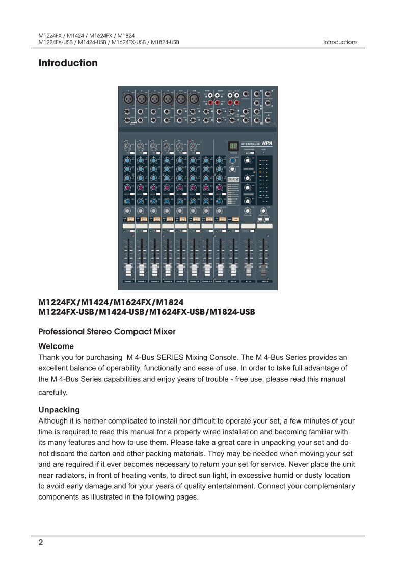
Introduction
Welcome Thank you for purchasing M 4-Bus SERIES Mixing Console. The M 4-Bus Series provides an excellent balance of operability, functionally and ease of use. In order to take full advantage of the M 4-Bus Series capabilities and enjoy years of trouble - free use, please read this manual
carefully.
UnpackingAlthough it is neither complicated to install nor difficult to operate your set, a few minutes of your time is required to read this manual for a properly wired installation and becoming familiar with its many features and how to use them. Please take a great care in unpacking your set and do not discard the carton and other packing materials. They may be needed when moving your set and are required if it ever becomes necessary to return your set for service. Never place the unit near radiators, in front of heating vents, to direct sun light, in excessive humid or dusty location to avoid early damage and for your years of quality entertainment. Connect your complementary components as illustrated in the following pages.
M1224FX/M1424/M1624FX/M1824M1224FX-USB/M1424-USB/M1624FX-USB/M1824-USB
Professional Stereo Compact Mixer
Introductions
3
M1224FX / M1424 / M1624FX / M1824M1224FX-USB / M1424-USB / M1624FX-USB / M1824-USB
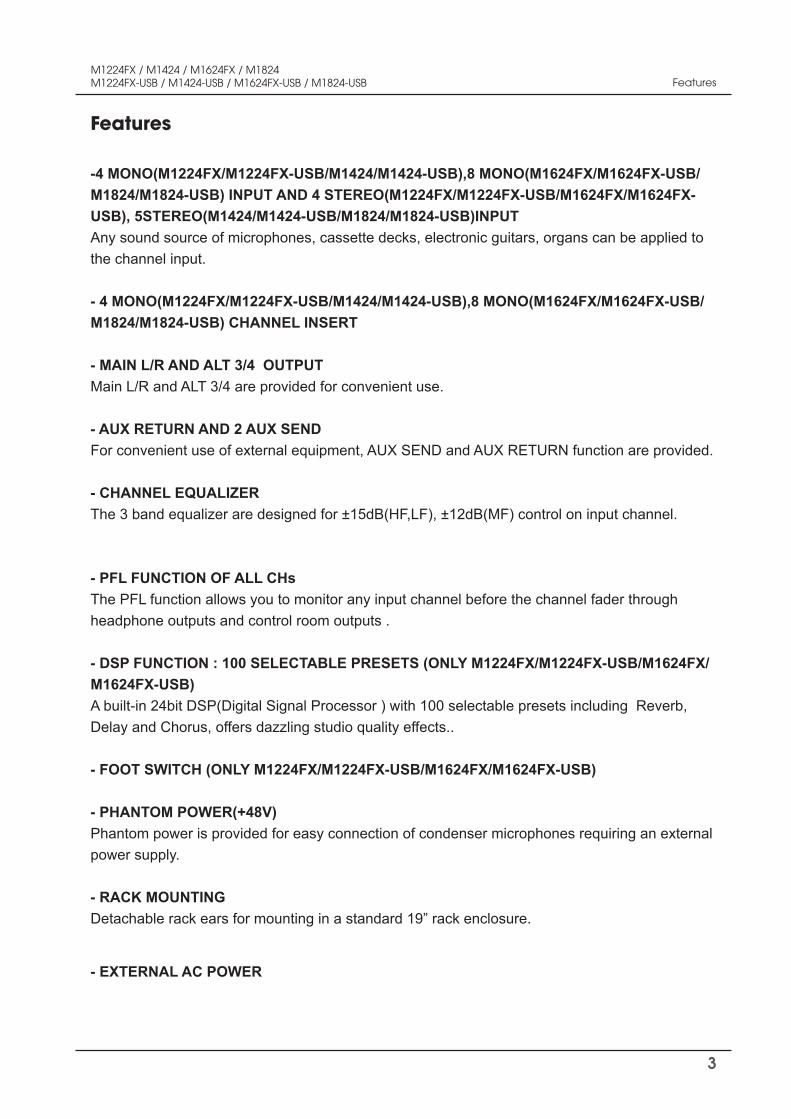
Features
Features
-4 MONO(M1224FX/M1224FX-USB/M1424/M1424-USB),8 MONO(M1624FX/M1624FX-USB/M1824/M1824-USB) INPUT AND 4 STEREO(M1224FX/M1224FX-USB/M1624FX/M1624FX-USB), 5STEREO(M1424/M1424-USB/M1824/M1824-USB)INPUT Any sound source of microphones, cassette decks, electronic guitars, organs can be applied to the channel input.
- 4 MONO(M1224FX/M1224FX-USB/M1424/M1424-USB),8 MONO(M1624FX/M1624FX-USB/M1824/M1824-USB) CHANNEL INSERT
- MAIN L/R AND ALT 3/4 OUTPUT Main L/R and ALT 3/4 are provided for convenient use.
- AUX RETURN AND 2 AUX SEND For convenient use of external equipment, AUX SEND and AUX RETURN function are provided.
- CHANNEL EQUALIZER The 3 band equalizer are designed for ±15dB(HF,LF), ±12dB(MF) control on input channel.
- PFL FUNCTION OF ALL CHs The PFL function allows you to monitor any input channel before the channel fader through headphone outputs and control room outputs .
- DSP FUNCTION : 100 SELECTABLE PRESETS (ONLY M1224FX/M1224FX-USB/M1624FX/M1624FX-USB) A built-in 24bit DSP(Digital Signal Processor ) with 100 selectable presets including Reverb, Delay and Chorus, offers dazzling studio quality effects..
- FOOT SWITCH (ONLY M1224FX/M1224FX-USB/M1624FX/M1624FX-USB)
- PHANTOM POWER(+48V) Phantom power is provided for easy connection of condenser microphones requiring an external power supply.
- RACK MOUNTINGDetachable rack ears for mounting in a standard 19” rack enclosure.
- EXTERNAL AC POWER
4
M1224FX / M1424 / M1624FX / M1824M1224FX-USB / M1424-USB / M1624FX-USB / M1824-USB Front Panels
CHANNEL 8
CH8
PFL
+10
5
0
5
10
15
20
3040
CHANNEL 11/12
CH11/12
PFL
+10
5
0
5
10
15
20
3040
CHANNEL 13/14
CH13/14
PFL
+10
5
0
5
10
15
20
3040
TRIM
PEAK
AUX
EFX
0 10
5
PRE/POST
MF2.5kHz
HF12kHz
LF80Hz
-30+14-6 -50
30
-15 +15
0
-12 +12
0
-15 +15
0
0 10
5
PAN
L R
TRIM
PEAK
AUX
EFX
0 10
5
PRE/POST
MF2.5kHz
HF12kHz
LF80Hz
-20+20-10 -50
30
-15 +15
0
-12 +12
0
-15 +15
0
0 10
5
BALANCE
L R
AUX
EFX
0 10
5
PRE/POST
MF2.5kHz
HF12kHz
LF80Hz
-15 +15
0
-12 +12
0
-15 +15
0
0 10
5
BALANCE
L R
75Hz 75Hz
MUTEALT 3/4
MUTEALT 3/4
MUTEALT 3/4
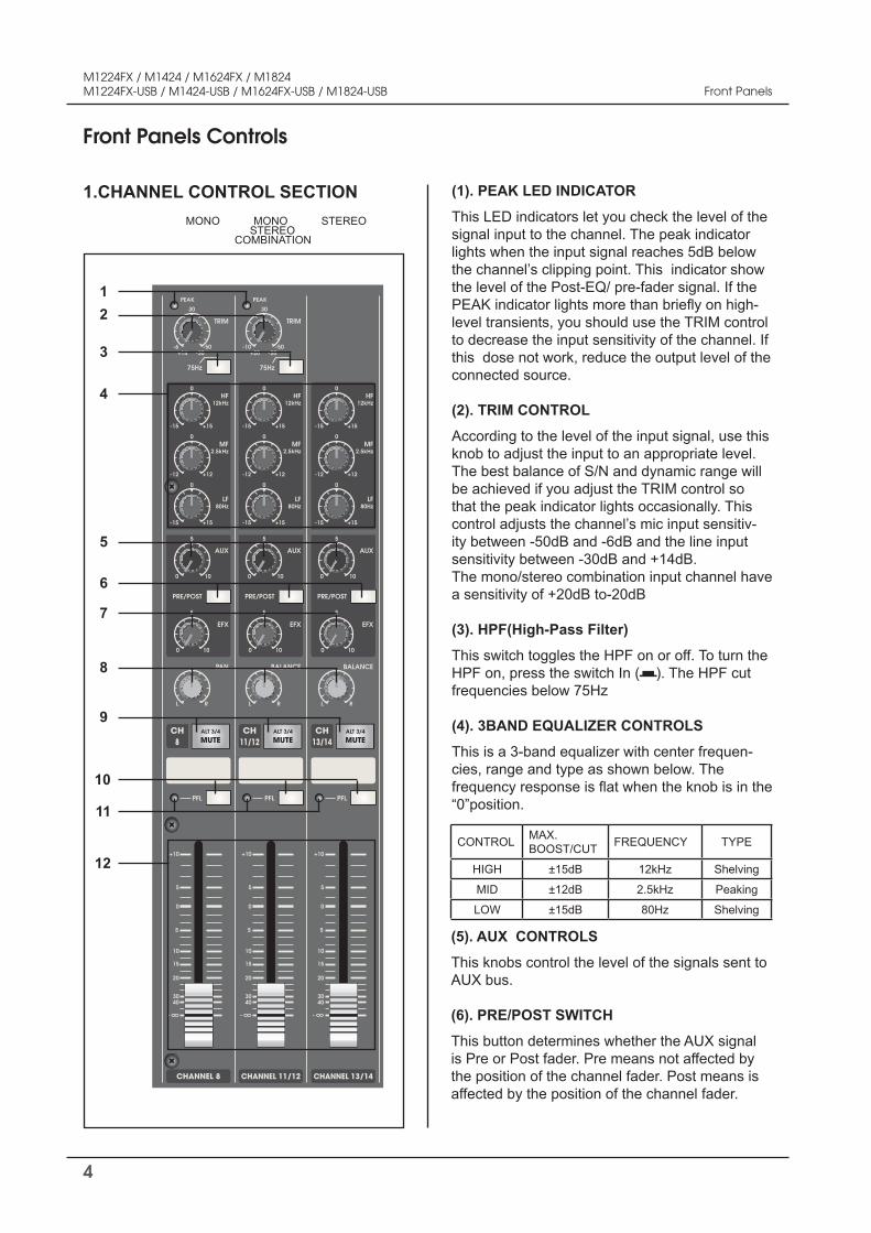
Front Panels Controls
(1). PEAK LED INDICATOR
This LED indicators let you check the level of the signal input to the channel. The peak indicator lights when the input signal reaches 5dB below the channel’s clipping point. This indicator show the level of the Post-EQ/ pre-fader signal. If the PEAK indicator lights more than briefly on high-level transients, you should use the TRIM control to decrease the input sensitivity of the channel. If this dose not work, reduce the output level of the connected source. (2). TRIM CONTROL
According to the level of the input signal, use this knob to adjust the input to an appropriate level. The best balance of S/N and dynamic range will be achieved if you adjust the TRIM control so that the peak indicator lights occasionally. This control adjusts the channel’s mic input sensitiv-ity between -50dB and -6dB and the line input sensitivity between -30dB and +14dB. The mono/stereo combination input channel have a sensitivity of +20dB to-20dB (3). HPF(High-Pass Filter)
This switch toggles the HPF on or off. To turn the HPF on, press the switch In ( ). The HPF cut frequencies below 75Hz (4). 3BAND EQUALIZER CONTROLS
This is a 3-band equalizer with center frequen-cies, range and type as shown below. The frequency response is flat when the knob is in the “0”position.
MONO MONO STEREO STEREO COMBINATION
1.CHANNEL CONTROL SECTION
(5). AUX CONTROLS
This knobs control the level of the signals sent to AUX bus. (6). PRE/POST SWITCH
This button determines whether the AUX signal is Pre or Post fader. Pre means not affected by the position of the channel fader. Post means is affected by the position of the channel fader.
CONTROL MAX. BOOST/CUT FREQUENCY TYPE
HIGH ±15dB 12kHz Shelving
MID ±12dB 2.5kHz Peaking
LOW ±15dB 80Hz Shelving
2
3
4
5
6
7
8
9
10
11
12
1
5
M1224FX / M1424 / M1624FX / M1824M1224FX-USB / M1424-USB / M1624FX-USB / M1824-USB
(7). EFX CONTROLS
This knobs control the level of the signals sent to EFX bus. The channel signals mixed by this bus have their overall level set by the EFX SEND Control to the EFX SEND jack on the front panel. The EFX bus signal is also fed into the internal digital signal processor(only M1224FX/M1224FX-USB/1624FX/M1624FX-USB). Since this control is placed after the channel fader, the signal level will be affected by the channel fader setting. (8). PAN /BAL CONTROL
PAN (Mono Channel) This control pans the channel signal across the master L and R buses, thus determining the per-ceived position of the sound from that channel in the output stereo sound field. If a PAN control is set all the way to the left,for example, the sound from that channel will be heard from the left speaker system only. If it is set all the way to the right, the sound will be heard from the right speaker system only. Intermediate settings will cause the sound to appear at corresponding locations in the stereo sound field.
BALANCE (Stereo Channel) This control adjusts the balance or the L/R posi-tion of the stereo input signal. Turning the BALANCE control to the left of center moves the apparent source toward the MAIN MIX L bus,turning it to the right moves the source toward the MAIN MIX R bus. (9). MUTE/ALT 3-4 SWITCH
When the Mute/ALT 3-4 switch is depressed, a channel output will be routed to the ALT 3-4 out-put instead of the main L/R out. ALT 3-4 bus offers you a second independent stereo sub mix with its own sub master stereo fader. (10). PFL SWITCH
When these switch is depressed, the channel input signal can be routed to the PFL bus. This switch allows you to monitor the pre-fader channel input signal through headphone outputs and control room outputs. (11). PFL INDICATOR
This indicator lights when the PFL switch is turned on.
(12). CHANNEL FADER
This is the channels main level control. It deter-mines the level of the signal that is sent from the channel to the master mixing and effect buses. It is the settings of the input channel faders that determine the mix, or the balance of sound levels between the instruments or other sources con-nected to the inputs. When a channel is not being used, its fader should be set at the minimum po-sition to prevent the addition of unwanted noise to the main program signal.
Front Panels Controls
Front Panels
6
M1224FX / M1424 / M1624FX / M1824M1224FX-USB / M1424-USB / M1624FX-USB / M1824-USB Front Panels
STEREO RETURN
AUX/EFX SEND
TAPE IN/USB PHONES/CTRL-RALT 3/4
MAIN
TAPE IN
PHANTOM POWER POWER
PROGRAM
SELECT
EFX RTN
EFX
PFL
+10
5
0
5
10
15
20
3040
ALT 3/4
TO MAIN L/R
+10
5
0
5
10
15
20
3040
+10
5
0
5
10
15
20
3040
ON
OFF
-20
-10
-7
-4
-2
0
+2
+4
+7
CLIP
AUX
0 10
5
AUX
0 10
5
MAIN
0 10
5
EFX
0 10
5
LEVEL
0 10
5 LEVEL
0 10
5
AUX
0 10
5PERFORMANCE
HALL REVERB
PLATE REVERB
SPRING REVERB
ECHO
FLANGE+VERB
CHORUS+VERB
ECHO+VERB
CHORUS
FLANGE
PFL
12 CH MIXING CONSOLE
M1224FX-USBHPA
L/ALT3 R/ALT4
MAIN L/R
ON
Front Panels Controls
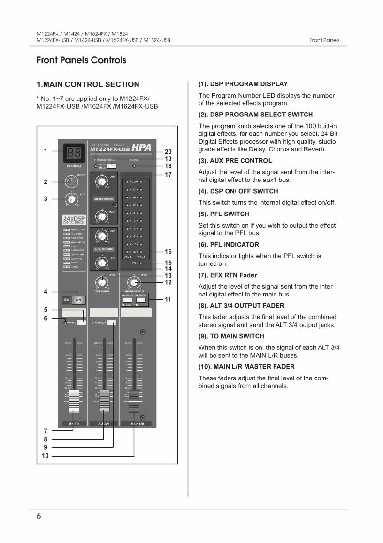
(1). DSP PROGRAM DISPLAY
The Program Number LED displays the number of the selected effects program.
(2). DSP PROGRAM SELECT SWITCH
The program knob selects one of the 100 built-in digital effects, for each number you select. 24 Bit Digital Effects processor with high quality, studio grade effects like Delay, Chorus and Reverb.
(3). AUX PRE CONTROL
Adjust the level of the signal sent from the inter-nal digital effect to the aux1 bus.
(4). DSP ON/ OFF SWITCH
This switch turns the internal digital effect on/off.
(5). PFL SWITCH
Set this switch on if you wish to output the effect signal to the PFL bus.
(6). PFL INDICATOR
This indicator lights when the PFL switch is turned on.
(7). EFX RTN Fader
Adjust the level of the signal sent from the inter-nal digital effect to the main bus.
(8). ALT 3/4 OUTPUT FADER
This fader adjusts the final level of the combined stereo signal and send the ALT 3/4 output jacks.
(9). TO MAIN SWITCH
When this switch is on, the signal of each ALT 3/4 will be sent to the MAIN L/R buses.
(10). MAIN L/R MASTER FADER
These faders adjust the final level of the com-bined signals from all channels.
* No. 1~7 are applied only to M1224FX/ M1224FX-USB /M1624FX /M1624FX-USB
1.MAIN CONTROL SECTION
2
1
4
56
7
98
10
11
1213141516
17181920
3
7
M1224FX / M1424 / M1624FX / M1824M1224FX-USB / M1424-USB / M1624FX-USB / M1824-USB Front Panels
(12). CTRL ROOM /PHONES CONTROL
Controls the level of the signal output to the PHONES jack and the CTRL ROOM L and R jacks.
(13). TAPE IN CONTROL
This control adjusts the level of the playback sig-nal that is inserted to the master mixing bus from the TAPE IN RCA jacks on the top panel.
14. MASTER SEND
* Master AUX Control
Adjust the level of the signal on the AUX bus to the corresponding AUX SEND jack.
* Master EFX Control
Adjust the level of the signal on the EFX bus. This is the signal that is output through the EFX SEND jack.
15. PFL INDICATOR
This indicator lights when the PFL switch is turned on.
16. OUTPUT LEVEL METER
A vertical row of ten LED show the continuous output level of main Output L/R or monitor 1/2 by signal select switch.
This type of display is free from over shoot prob-lem of mechanical meters and is highly visible under poor lighting conditions. The 0 LED means an output level of +4dB, for +4dB output-that’s the rated level.
17. STEREO RETURN CONTROL
* AUX CONTROL Adjust the level of the mixed L/R signal sent from the RETURN jack (L (MONO) and R) to the AUX bus.
* MAIN CONTROL Adjust the level of the mixed L/R signal sent from the RETURN jack (L (MONO) and R) to the Main L/R bus.
18. POWER INDICATOR
This indicator lights when the power switch is turned on.
19. PHANTOM POWER SWITCH
This switch toggles phantom power on/off. If you set the switch on, the mixer supplies power to all channels that provide XLR mic input jacks. Set this switch on when using one or more con-denser microphones.
NOTE:When this switch is on, the mixer supplies DC +48V power to pins 2 and 3 of all XLR-type MIC INPUT jacks.
Front Panels Controls
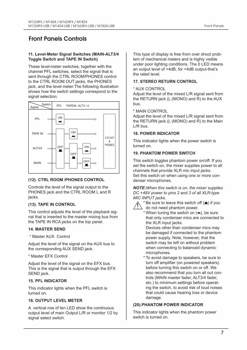
11. Level-Meter Signal Switches (MAIN-ALT3/4 Toggle Switch and TAPE IN Switch)
These level-meter switches, together with the channel PFL switches, select the signal that is sent through the CTRL ROOM/PHONES control to the CTRL ROOM OUT jacks, the PHONES jack, and the level meter.The following illustration shows how the switch settings correspond to the signal selection.
SignalSwitch PFL TAPEIN ALT3 / 4
PFL ON
TAPE IN
OFF
OFF
OFF
ALT3/4
MAIN
ON
ON
C-R OUT&
PHONES
Be sure to leave this switch off ( ) if you do not need phantom power. When tuning the switch on ( ), be sure that only condenser mics are connected to the XLR input jacks. Devices other than condenser mics may be damaged if connected to the phantom power supply. Note, however, that the switch may be left on without problem when connecting to balanced dynamic microphones. To avoid damage to speakers, be sure to turn off amplifier (on powered speakers) before turning this switch on or off. We also recommend that you turn all out con-trols (MAIN master fader, ALT3/4 fader, etc.) to minimum settings before operat-ing the switch, to avoid risk of loud noises that could cause hearing loss or device damage.
(20).PHANTOM POWER INDICATOR
This indicator lights when the phantom power switch is turned on.
* * *
8
M1224FX / M1424 / M1624FX / M1824M1224FX-USB / M1424-USB / M1624FX-USB / M1824-USB Front Panels
Front Panels Controls
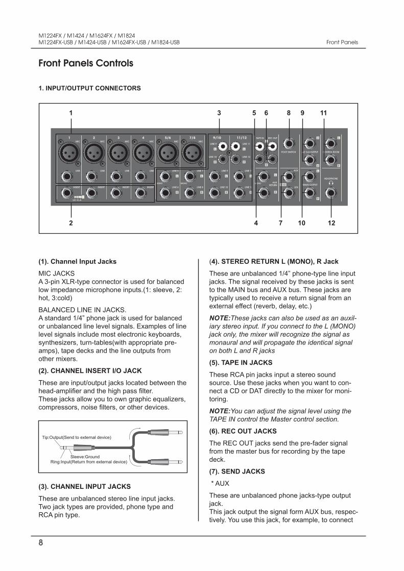
1. INPUT/OUTPUT CONNECTORS
(4). STEREO RETURN L (MONO), R Jack
These are unbalanced 1/4” phone-type line input jacks. The signal received by these jacks is sent to the MAIN bus and AUX bus. These jacks are typically used to receive a return signal from an external effect (reverb, delay, etc.)
NOTE:These jacks can also be used as an auxil-iary stereo input. If you connect to the L (MONO) jack only, the mixer will recognize the signal as monaural and will propagate the identical signal on both L and R jacks
(5). TAPE IN JACKS
These RCA pin jacks input a stereo sound source. Use these jacks when you want to con-nect a CD or DAT directly to the mixer for moni-toring.
NOTE:You can adjust the signal level using the TAPE IN control the Master control section.
(6). REC OUT JACKS
The REC OUT jacks send the pre-fader signal from the master bus for recording by the tape deck.
(7). SEND JACKS
* AUX
These are unbalanced phone jacks-type output jack. This jack output the signal form AUX bus, respec-tively. You use this jack, for example, to connect
MONOMONOMONO AUXRETURN
TAPE IN REC OUT
ALT 3/4 OUTPUTFOOT SWITCH
MAIN OUTPUT
CONTROL ROOM
LINE
INSERT
1MIC
OUT IN
LINE
INSERT
2MIC
LINE
INSERT
3MIC
LINE
INSERT
4MIC
LINE 5
LINE 6
5/6MIC
LINE 7
LINE 8
7/8
LINE 9
LINE 10
LINE 9
LINE 10
LINE 11
LINE 12
9/10MIC
LINE 11
LINE 12
11/12
AUX
EFX
HEADPHONE
(1). Channel Input Jacks
MIC JACKS A 3-pin XLR-type connector is used for balanced low impedance microphone inputs.(1: sleeve, 2: hot, 3:cold)
BALANCED LINE IN JACKS. A standard 1/4” phone jack is used for balanced or unbalanced line level signals. Examples of line level signals include most electronic keyboards, synthesizers, turn-tables(with appropriate pre-amps), tape decks and the line outputs from other mixers.
(2). CHANNEL INSERT I/O JACK
These are input/output jacks located between the head-amplifier and the high pass filter. These jacks allow you to own graphic equalizers, compressors, noise filters, or other devices.
Tip:Output(Send to external device)
Sleeve:GroundRing:Input(Return from external device)
(3). CHANNEL INPUT JACKS
These are unbalanced stereo line input jacks. Two jack types are provided, phone type and RCA pin type.
1
2
3 5
4 7
6 8
10
9 11
12

9
M1224FX / M1424 / M1624FX / M1824M1224FX-USB / M1424-USB / M1624FX-USB / M1824-USB
NOTE:The signal monitored by these jacks is selected by the settings of the MAIN-ALT3/4 toggle switch, the TAPE IN switch, and the PFL switches on the input channels.
to an effector or to a cue box or other such moni-toring system.
* EFX
These are unbalanced phone jacks-type output jack that output the signal form the EFX bus.
You use this jack, for example, to connect to an external effector
(8). FOOT SWITCH JACK (Applied only to M1224FX/M1224FX-USB / M1624FX/M1624FX-USB)
This phone input jack can connect to the foot switch. With the foot switch connected, you can use your foot to toggle the digital effects ON and OFF
(9). ALT 3/4 OUTPUT JACKS
These are unbalanced 1/4” phone type output jacks which output the signals of ALT 3/4 bus.Use these jacks to connect to the input jack of an MTR, external mixer, or other such device.
(10). MAIN L/R OUTPUT JACKS
These jacks deliver stereo output of the mixer signal. You use these jacks, for example, to connect to the power amplifier driving your main speakers. You also use these jacks when you wish to record the signal utilizing the level control applied by the main fader in the Master Control section. TRS phone-type balanced output jack.
(11). CONTROL ROOM OUTPUT JACKS
Use these stereo phone-type output jacks to con-nect to your monitor system.
NOTE:The signal monitored by these jacks is selected by the settings of the MAIN-ALT3/4 toggle switch, the TAPE IN switch, and the PFL switches on the input channels.
(12). PHONES JACK
Connect for headphones. This is stereo phone-type output jack.
(1/4" Phone 3 Section Connector)
( O )
(1/4" Phone 2 Section Connector)
( X )
Front Panels Controls
Front Panels

10
M1224FX / M1424 / M1624FX / M1824M1224FX-USB / M1424-USB / M1624FX-USB / M1824-USB Rear Panels
Rear Panels Controls
1. AC ADAPTOR IN CONNECTOR
Connects to the included PA-M1224 power adaptor.
NOTE:Use only the PA-M1224 adaptor included with this mixer. Use of a different adaptor may result in fire or electric shock.
2. POWER SWITCH
Use this switch to power mixer to ON or OFF.
3.MAIN L/R OUTPUT XLR JACK.
4.USB PORT CONNECT STANDARD USB CA-BLE HER
NOTE:USB only the M1224FX-USB / M1424-USB / M1624FX-USB / M1824-USB
2 3 41
11
M1224FX / M1424 / M1624FX / M1824M1224FX-USB / M1424-USB / M1624FX-USB / M1824-USB
The M series consoles have a built-in stereo USB audio interface allowing you to record and play-back from a PC using virtually any digital recording software. In addition, the M series consoles feature powerful routing options that let you route your USB digital recording and playback.
Connecting the M series to your computer is a sim-ple procedure that takes just a few minutes. Since the M Series consoles are USB compliant, you can use either a MAC or PC, connect USB cable a nd plug IN and play. You will be able to control your M series using the standard audio interface controls in the MAC or Windows operating system. You will find detailed instructions on setting up with MAC OS and Windows in the following sections of this manual.
Getting Started with Windows XP
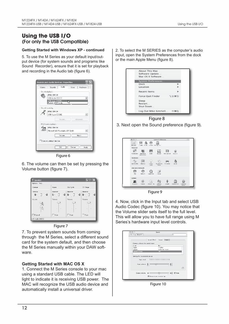
1. The first time you plug the M series into a USB port, Windows will install the universal drivers for that port. A balloon tip will pop up, telling you it has found the USB Audio codec (figure 1).
Figure 1
2.When it is finished installing the drivers, it will say “Your new hardware is installed and ready to use” (figure 2).Note: This balloon will not pop up again for the same USB port.
Figurt 2
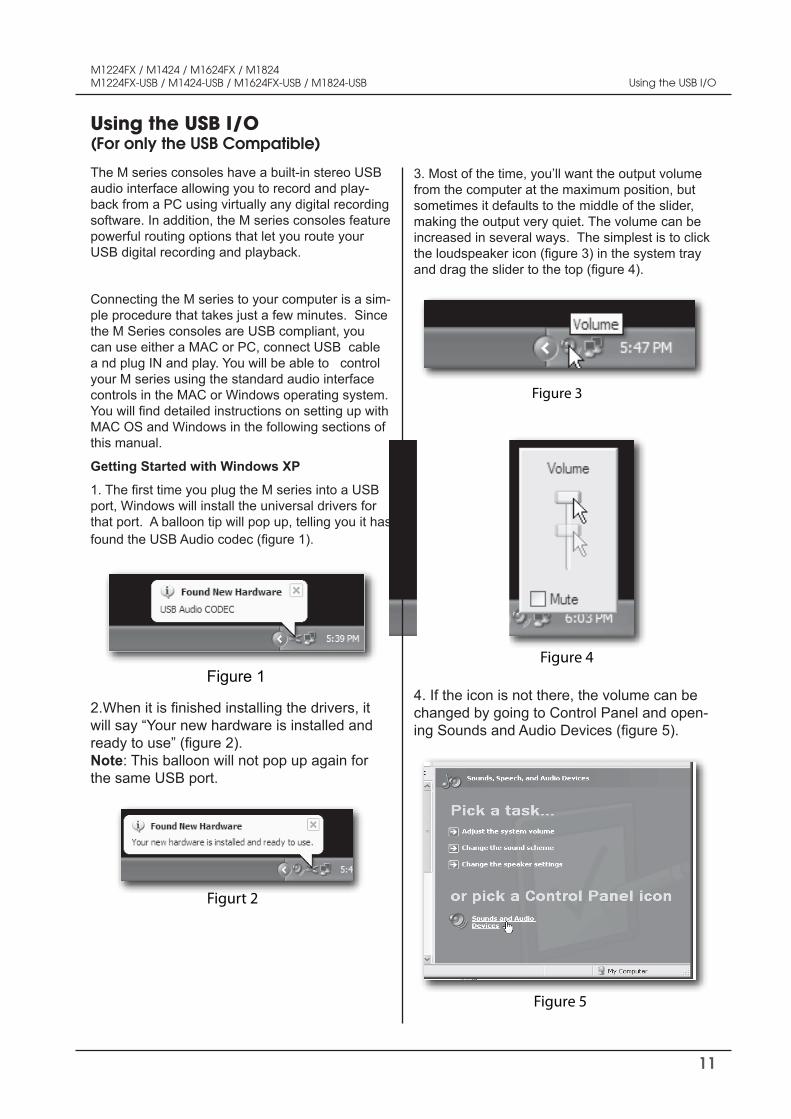
3. Most of the time, you’ll want the output volume from the computer at the maximum position, but sometimes it defaults to the middle of the slider, making the output very quiet. The volume can be increased in several ways. The simplest is to click the loudspeaker icon (figure 3) in the system tray and drag the slider to the top (figure 4).
Figure 3
Figure 4
4. If the icon is not there, the volume can be changed by going to Control Panel and open-ing Sounds and Audio Devices (figure 5).
Figure 5
Using the USB I/O(For only the USB Compatible)
Using the USB I/O
12
M1224FX / M1424 / M1624FX / M1824M1224FX-USB / M1424-USB / M1624FX-USB / M1824-USB
Getting Started with Windows XP - continued
5. To use the M Series as your default input/out-put device (for system sounds and programs like Sound Recorder), ensure that it is set for playback and recording in the Audio tab (figure 6).
Figure 6
6. The volume can then be set by pressing the Volume button (figure 7).
Figure 7 7. To prevent system sounds from coming through the M Series, select a different sound card for the system default, and then choose the M Series manually within your DAW soft-ware.
Getting Started with MAC OS X 1. Connect the M Series console to your mac using a standard USB cable. The LED will light to indicate it is receiving USB power. The MAC will recognize the USB audio device and automatically install a universal driver.
2. To select the M SERIES as the computer’s audio input, open the System Preferences from the dock or the main Apple Menu (figure 8).
Figure 8 3. Next open the Sound preference (figure 9).
Figure 9
4. Now, click in the Input tab and select USB Audio Codec (figure 10). You may notice that the Volume slider sets itself to the full level. This will allow you to have full range using M Series’s hardware input level controls.
Figure 10
Using the USB I/O(For only the USB Compatible)
Using the USB I/O

13
M1224FX / M1424 / M1624FX / M1824M1224FX-USB / M1424-USB / M1624FX-USB / M1824-USB
Getting Started with MAC OS X - continued
5. Next, click in the Output tab and select USB Audio Codec (figure 11). You may notice that the Volume slider sets itself to the full level. This will allow you to have full range using M Series’ hard-ware MAIN Volume control.
Figure 11
At this point you can begin using your M Series console with most any audio recording software, but you need to select it as an input and output device within the DAW. When se-lecting the inputs and outputs just look for and select the USB Audio Codec. Recording from the M Series’ USB I/O For recording a live performance, you can send the Be sure that the euch channel input volume proper level is set to to send the MAIN Left and Right mix to the USB input. The USB I/O is always active and signal, the signal sent to the computer will be comprised of the input channels that are assigned to the MAIN Left and Right Bus. The mix level follows the chan-nel FADER and the stereo image set by the channel’s PAN control.
You can also assign the USB out to feed from the AUX1 and AUX2 outputs enabling you to build a stereo mix for recording that’s independent from the house sound system. Press the USB SEND switch down to send the AUX1 and AUX2 mix to the USB input.Playing Back From the M Series’ USB I/O
For playback, you can return the USB stereo signal directly into the TAPE IN left and right mix bus so that the playback from the PC sums with the MAIN mix on the console.
To hear the USB playback in the MAIN mix, be sure that the TAPE/USB volume is set to proper level.
Using the USB I/O(For only the USB Compatible)
Using the USB I/O
14
M1224FX / M1424 / M1624FX / M1824M1224FX-USB / M1424-USB / M1624FX-USB / M1824-USB
- In all cases, use good quality twin screened audio cable. Check for instability at the output. - Always connect both conductors at both ends, and ensure that the screen is only connected at one end. - Do not disconnect the mains earth from each piece of equipment. This is needed to provided both safety and screen returns to the system star point. - Equipment which has balanced inputs and outputs may need to be electrically isolated from the equip-ment rack and/or other equipment, to avoid earth loops.
It is important to remember that all equipment which is connected to the mains it a potential source of hum and interference and may radiate both electrostatic or electromagnetic radiation. In addition, the mains will also act as a carrier for many forms of RF interference generated by electric motors, air-conditioning units, thyristor light dimmers etc. Unless the earth system is clean, all attempts to improve hum noise levels will be futile. In extreme cases there will be no alternative but to provide a completely separate and independ-ent ‘technical earth’ to replace the incoming ‘noisy earth’. However, always consult your local electricity supply authority to ensure that safety regulations are not being infringed.
Points to Remember
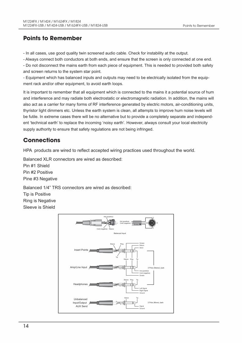
HPA products are wired to reflect accepted wiring practices used throughout the world.
Balanced XLR connectors are wired as described: Pin #1 Shield Pin #2 Positive Pine #3 Negative
Balanced 1/4” TRS connectors are wired as described: Tip is Positive Ring is Negative Sleeve is Shield
Connections
Insert Points
Amp/Line Input
Headphones
UnbalancedInput/Output
AUX Send
Ring
Ring
TipTip
Sleeve
Sleeve
SendReturnScreen
Hot (positive)Cold (negative)
Screen
Left SignalRight SignalGround
SignalGround
3 Pole (Stereo) Jack
2 Pole (Mono) Jack
Ring TipSleeve
TipSeeve
2
1
3
Balanced Input
Hot (positive)
Hot (positive)
Sleeve
Screen
Cold (negative)
Cold (negative)
Points to Remember
15
M1224FX / M1424 / M1624FX / M1824M1224FX-USB / M1424-USB / M1624FX-USB / M1824-USB
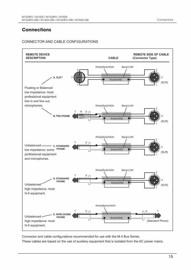
CONNECTOR AND CABLE CONFIGURATIONS
Connections
Connections
2
3
1
T R S
2
3
1
2
3
1
(XLR)
(XLR)
White(Red)/HIGH
A. XLR**
B. TRS PHONE
Black/LOW
Shield/GND
White(Red)/HIGH Black/LOW
Shield/GND
T S
T TSS
2
3
1(XLR)
(Standard Phone)
D. STANDARD PHONE
E. SHIELD/GND PHONE
White(Red)/HIGH Black/LOW
Shield/GND
White(Black)/HIGH
Shield/GND
T S2
3
1(XLR)
C. STANDARD PHONE
White(Red)/HIGH Black/LOW
Shield/GND
Floating or Balancedlow impedance: most professional equipmentline in and line out,microphones.
Unbalancedlow impedance: someprofessional equipmentand microphones.
Unbalancedhigh impedance: most hi-fi equipment.
Unbalancedhigh impedance: most hi-fi equipment.
REMOTE DEVICE REMOTE SIDE OF CABLEDESCRIPTION CABLE (Connector Type)
Connector and cable configurations recommended for use with the M 4 Bus Series. These cables are based on the use of auxiliary equipment that is isolated from the AC power mains.
16
M1224FX / M1424 / M1624FX / M1824M1224FX-USB / M1424-USB / M1624FX-USB / M1824-USB
Applications
Applications
MONOMONOMONO AUXRETURN
TAPE IN REC OUT
ALT 3/4 OUTPUTFOOT SWITCH
MAIN OUTPUT
CONTROL ROOM
LINE
INSERT
1MIC
OUT IN
LINE
INSERT
2MIC
LINE
INSERT
3MIC
LINE
INSERT
4MIC
LINE 5
LINE 6
5/6MIC
LINE 7
LINE 8
7/8
LINE 9
LINE 10
LINE 9
LINE 10
LINE 11
LINE 12
9/10MIC
LINE 11
LINE 12
11/12
AUX
EFX
HEADPHONE
Microphone
Guitar Powered MonitorSpeakers
Foot Switch
Sound Source(CD,MD,DAT,Cassette,Video etc.)
Master Recorder(MD,DAT.)
Synthesizer
MTR
Rhythm Machine
Effector
Effector
COMPACT DISC PLAYER
PROGRAM EJECT
POWER
REPEAT SKIP FWD
MIN MAX
PLAY/PAUSE LEVELSTOP
REW
COMPACT DISC PLAYER
PROGRAM EJECT
POWER
REPEAT SKIP FWD
MIN MAX
PLAY/PAUSE LEVELSTOP
REW
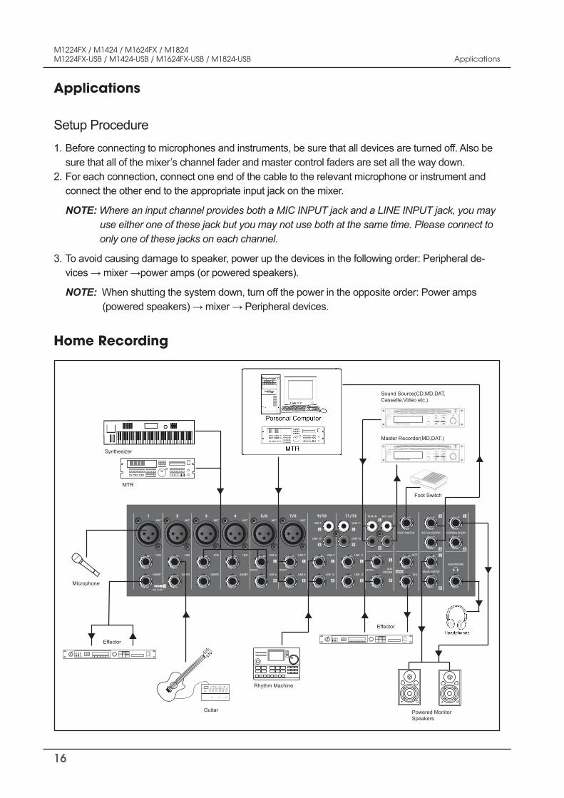
Before connecting to microphones and instruments, be sure that all devices are turned off. Also be sure that all of the mixer’s channel fader and master control faders are set all the way down. For each connection, connect one end of the cable to the relevant microphone or instrument and connect the other end to the appropriate input jack on the mixer.
NOTE: Where an input channel provides both a MIC INPUT jack and a LINE INPUT jack, you may use either one of these jack but you may not use both at the same time. Please connect to only one of these jacks on each channel.
To avoid causing damage to speaker, power up the devices in the following order: Peripheral de-vices → mixer →power amps (or powered speakers).
NOTE: When shutting the system down, turn off the power in the opposite order: Power amps (powered speakers) → mixer → Peripheral devices.
1. 2.
3.
Setup Procedure
Home Recording
17
M1224FX / M1424 / M1624FX / M1824M1224FX-USB / M1424-USB / M1624FX-USB / M1824-USB Application
MONOMONOMONO AUXRETURN
TAPE IN REC OUT
ALT 3/4 OUTPUTFOOT SWITCH
MAIN OUTPUT
CONTROL ROOM
LINE
INSERT
1MIC
OUT IN
LINE
INSERT
2MIC
LINE
INSERT
3MIC
LINE
INSERT
4MIC
LINE 5
LINE 6
5/6MIC
LINE 7
LINE 8
7/8
LINE 9
LINE 10
LINE 9
LINE 10
LINE 11
LINE 12
9/10MIC
LINE 11
LINE 12
11/12
AUX
EFX
HEADPHONE
Guitar
Main Speakers(External)
Power Amp
Synthesizer
Effector
Effector
Stage (Internal)
ST
AUX(PRE )
Audience(External) ST
Microphone
Bass
Foot Switch
CD Player
Monitor Speakers(Internal)
Power Amp
CD,Cassette,orDAT Recorder
PRE
DI
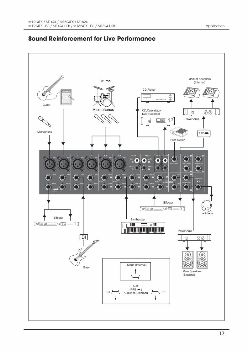
Sound Reinforcement for Live Performance
18
M1224FX / M1424 / M1624FX / M1824M1224FX-USB / M1424-USB / M1624FX-USB / M1824-USB
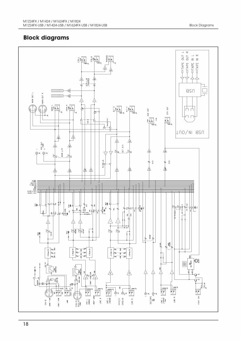
Block diagrams
Block Diagrams
19
M1224FX / M1424 / M1624FX / M1824M1224FX-USB / M1424-USB / M1624FX-USB / M1824-USB Specifications
Specifications
*0dB=0.775Vrms, 0dBV=1Vrms
-GENERAL
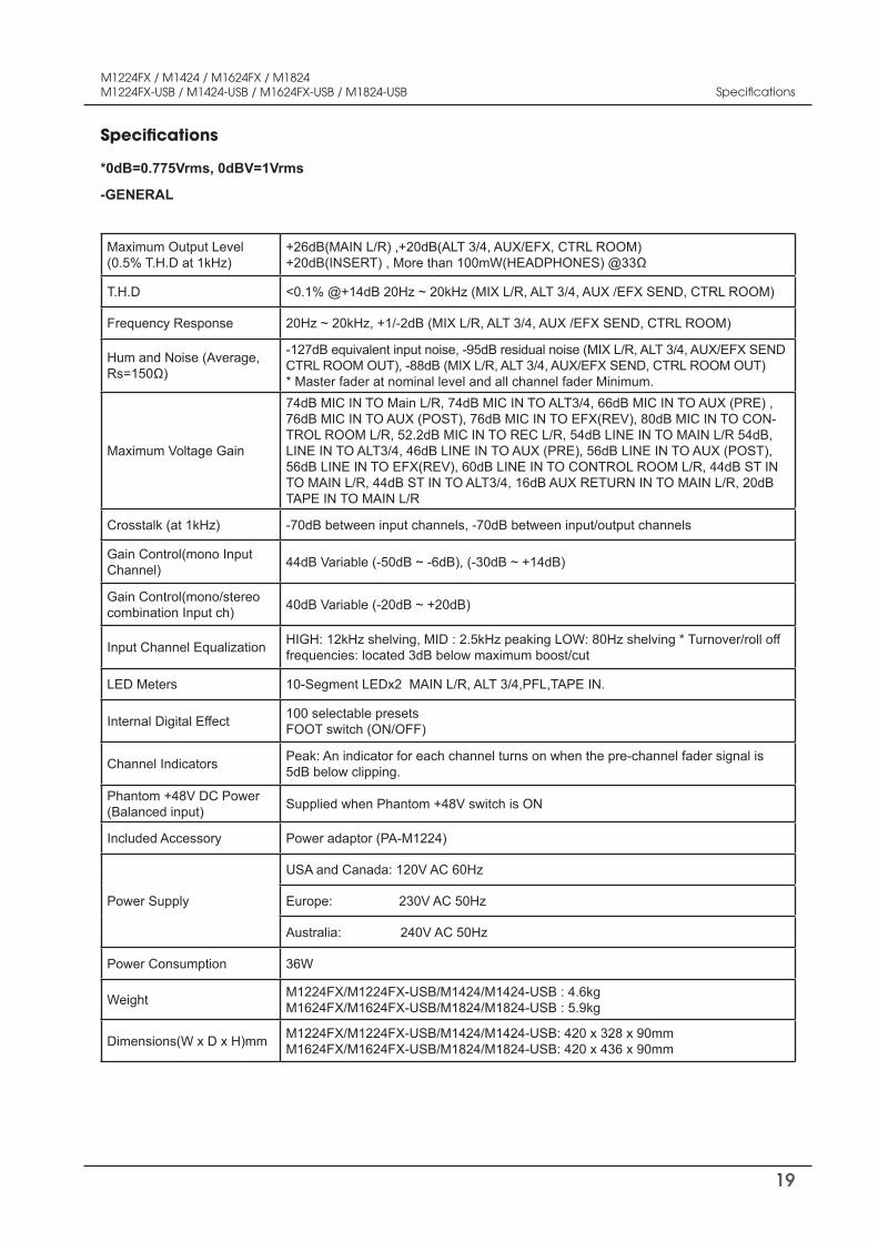
Maximum Output Level (0.5% T.H.D at 1kHz)
+26dB(MAIN L/R) ,+20dB(ALT 3/4, AUX/EFX, CTRL ROOM) +20dB(INSERT) , More than 100mW(HEADPHONES) @33Ω
T.H.D <0.1% @+14dB 20Hz ~ 20kHz (MIX L/R, ALT 3/4, AUX /EFX SEND, CTRL ROOM)
Frequency Response 20Hz ~ 20kHz, +1/-2dB (MIX L/R, ALT 3/4, AUX /EFX SEND, CTRL ROOM)
Hum and Noise (Average, Rs=150Ω)
-127dB equivalent input noise, -95dB residual noise (MIX L/R, ALT 3/4, AUX/EFX SEND CTRL ROOM OUT), -88dB (MIX L/R, ALT 3/4, AUX/EFX SEND, CTRL ROOM OUT) * Master fader at nominal level and all channel fader Minimum.
Maximum Voltage Gain
74dB MIC IN TO Main L/R, 74dB MIC IN TO ALT3/4, 66dB MIC IN TO AUX (PRE) , 76dB MIC IN TO AUX (POST), 76dB MIC IN TO EFX(REV), 80dB MIC IN TO CON-TROL ROOM L/R, 52.2dB MIC IN TO REC L/R, 54dB LINE IN TO MAIN L/R 54dB, LINE IN TO ALT3/4, 46dB LINE IN TO AUX (PRE), 56dB LINE IN TO AUX (POST), 56dB LINE IN TO EFX(REV), 60dB LINE IN TO CONTROL ROOM L/R, 44dB ST IN TO MAIN L/R, 44dB ST IN TO ALT3/4, 16dB AUX RETURN IN TO MAIN L/R, 20dB TAPE IN TO MAIN L/R
Crosstalk (at 1kHz) -70dB between input channels, -70dB between input/output channels
Gain Control(mono Input Channel) 44dB Variable (-50dB ~ -6dB), (-30dB ~ +14dB)
Gain Control(mono/stereo combination Input ch) 40dB Variable (-20dB ~ +20dB)
Input Channel Equalization HIGH: 12kHz shelving, MID : 2.5kHz peaking LOW: 80Hz shelving * Turnover/roll off frequencies: located 3dB below maximum boost/cut
LED Meters 10-Segment LEDx2 MAIN L/R, ALT 3/4,PFL,TAPE IN.
Internal Digital Effect 100 selectable presetsFOOT switch (ON/OFF)
Channel Indicators Peak: An indicator for each channel turns on when the pre-channel fader signal is 5dB below clipping.
Phantom +48V DC Power(Balanced input) Supplied when Phantom +48V switch is ON
Included Accessory Power adaptor (PA-M1224)
Power Supply
USA and Canada: 120V AC 60Hz
Europe: 230V AC 50Hz
Australia: 240V AC 50Hz
Power Consumption 36W
Weight M1224FX/M1224FX-USB/M1424/M1424-USB : 4.6kgM1624FX/M1624FX-USB/M1824/M1824-USB : 5.9kg
Dimensions(W x D x H)mm M1224FX/M1224FX-USB/M1424/M1424-USB: 420 x 328 x 90mm M1624FX/M1624FX-USB/M1824/M1824-USB: 420 x 436 x 90mm
20
M1224FX / M1424 / M1624FX / M1824M1224FX-USB / M1424-USB / M1624FX-USB / M1824-USB Specifications
Specifications
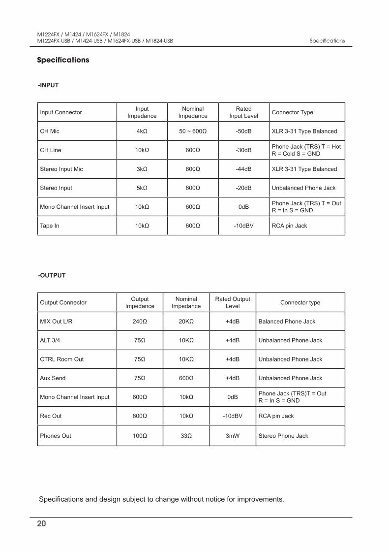
Specifications and design subject to change without notice for improvements.
-INPUT
Input Connector Input Impedance
Nominal Impedance
Rated Input Level Connector Type
CH Mic 4kΩ 50 ~ 600Ω -50dB XLR 3-31 Type Balanced
CH Line 10kΩ 600Ω -30dB Phone Jack (TRS) T = Hot R = Cold S = GND
Stereo Input Mic 3kΩ 600Ω -44dB XLR 3-31 Type Balanced
Stereo Input 5kΩ 600Ω -20dB Unbalanced Phone Jack
Mono Channel Insert Input 10kΩ 600Ω 0dB Phone Jack (TRS) T = Out R = In S = GND
Tape In 10kΩ 600Ω -10dBV RCA pin Jack
-OUTPUT
Output Connector Output Impedance
Nominal Impedance
Rated Output Level Connector type
MIX Out L/R 240Ω 20KΩ +4dB Balanced Phone Jack
ALT 3/4 75Ω 10KΩ +4dB Unbalanced Phone Jack
CTRL Room Out 75Ω 10KΩ +4dB Unbalanced Phone Jack
Aux Send 75Ω 600Ω +4dB Unbalanced Phone Jack
Mono Channel Insert Input 600Ω 10kΩ 0dB Phone Jack (TRS)T = Out R = In S = GND
Rec Out 600Ω 10kΩ -10dBV RCA pin Jack
Phones Out 100Ω 33Ω 3mW Stereo Phone Jack
21
M1224FX / M1424 / M1624FX / M1824M1224FX-USB / M1424-USB / M1624FX-USB / M1824-USB
Procedures
Take steps to insure the problem is not related to operator error or other products within the system. Infor-mation provided in the troubleshooting portion of this manual may help with this process. Once it is certain that the problem is related to the product contact your warranty provider as described in the warranty sec-tion of this manual.
Schematic
A Schematic is available by contacting your warranty provider.
Parts List
A Parts List is available by contacting your warranty provider.
Service
Variations
Products supplied through legitimate sources are compatible with local AC power requirements.
Options
No optional items are available for this product.
Variations and Options
Warranty terms and conditions vary by country and may not be the same for all products. Terms and con-ditions of warranty for a given product may be determined first by locating the appropriate country which the product was purchased in, then by locating the product type.
To obtain specific warranty information and available service locations contact HPA directly or the author-ized HPA Distributor for your specific country or region.
Warranty
Service