User Guide forProfibus Protocol on Elektronikon ComBox-P Name Mark IV : User Guide Serc. Class 1102 K/1 Detail User Guide Profibus Protocol on Elektronikon ComBox-P PC OwnerEdition Modified from Print date AII 00 Family Written by Compare Replaces Designation CTE-PVT Design checked. Production checked. Approved Date 9820 3582 03
2 The Physical set-up...........................................................................................................................................................4
2.1 Profibus & the Network............................................................................................................................................4
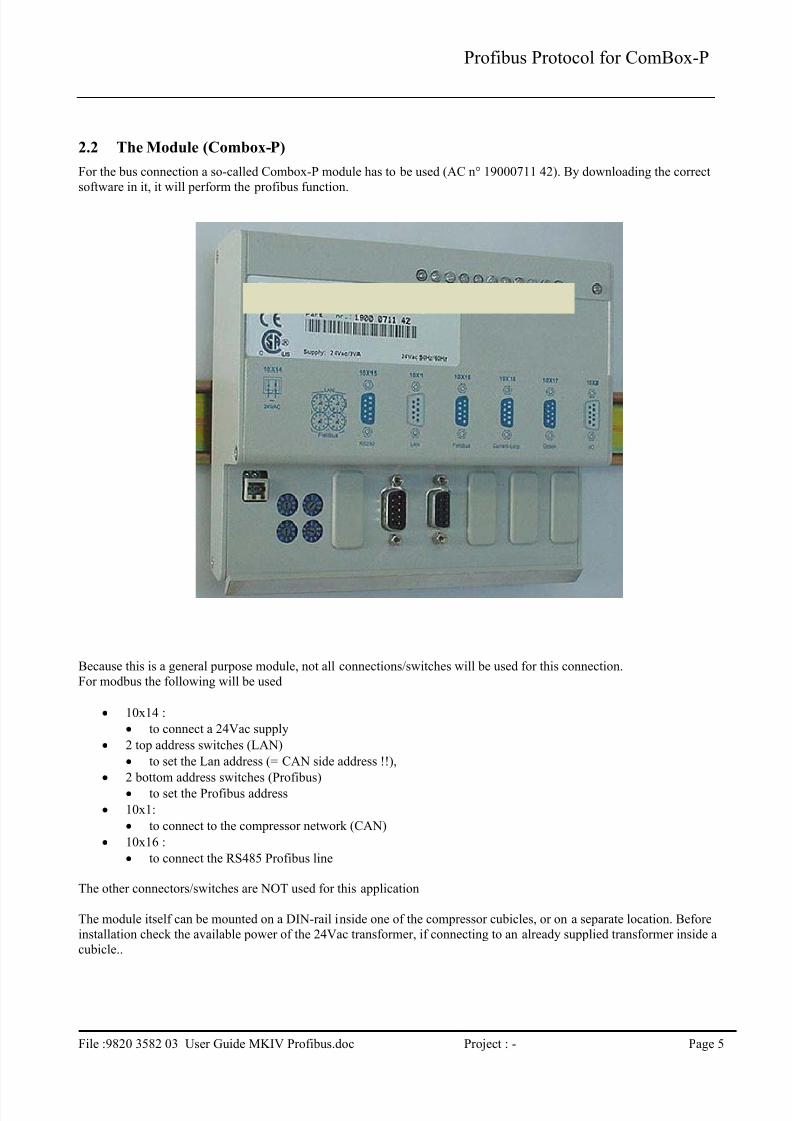
2.2 The Module (Combox-P)..........................................................................................................................................52.3 LED’s........................................................................................................................................................................6
2.4.1 Power Supply....................................................................................................................................................7
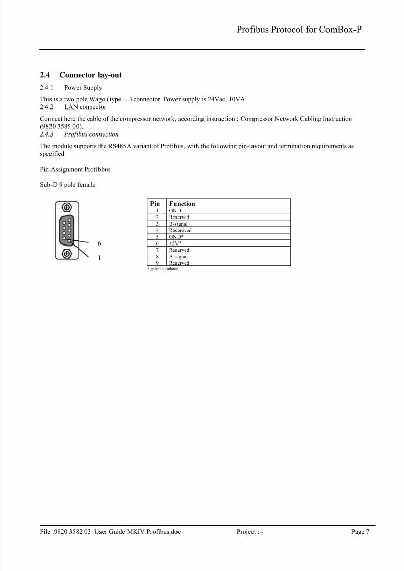
2.4.2 LAN connector .................................................................................................................................................72.4.3 Profibus connection ..........................................................................................................................................7
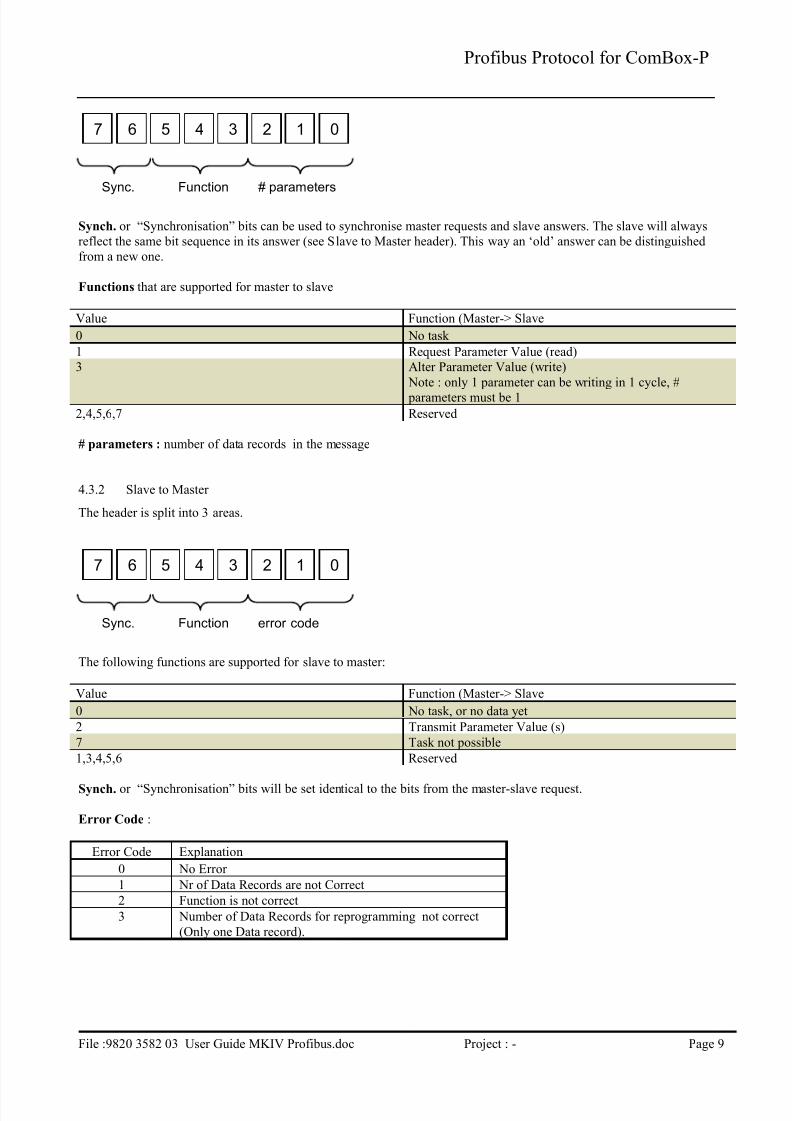
4.3.1 Master to Slave .................................................................................................................................................8
4.3.2 Slave to Master .................................................................................................................................................9
4.4 Data Record ............................................................................................................................................................10
4.4.2 Profibus Parameter ID for Data Reading ........................................................................................................11
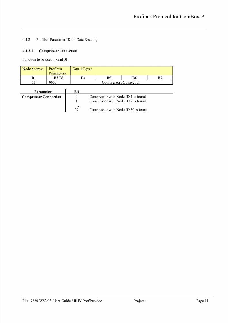
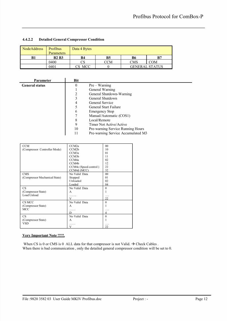
4.4.2.1 Compressor connection...............................................................................................................................114.4.2.2 Detailed General Compressor Condition ....................................................................................................12
1.1.1.1.2 Temperature Input.................................................................................................................................14
4.4.3.4.5 Current Input.........................................................................................................................................14
4.4.4.2 Multi Compressor Controller Counters.......................................................................................................17
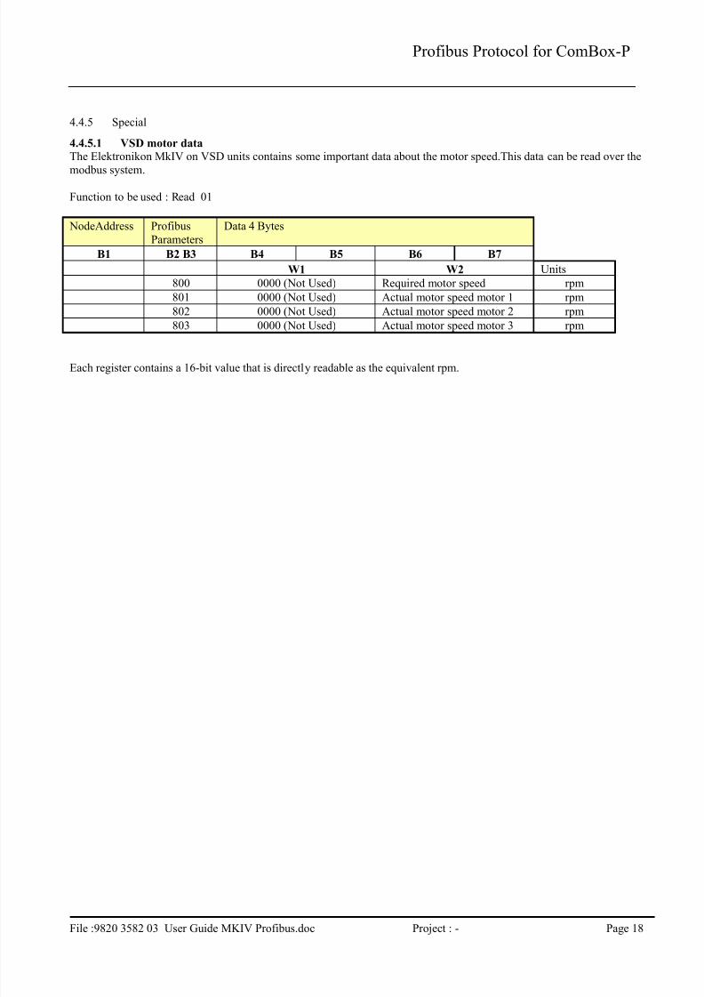
4.4.5 Special.............................................................................................................................................................184.4.5.1 VSD motor data ..........................................................................................................................................18
4.5 Profibus parameters for change...............................................................................................................................19
4.5.1 Load/Unload Pressure Band change ...............................................................................................................194.5.2 VSD Setpoint change......................................................................................................................................19
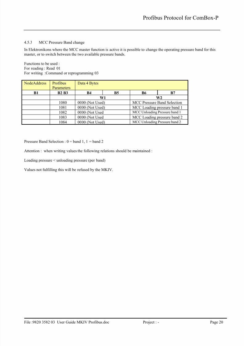
4.5.3 MCC Pressure Band change ...........................................................................................................................20
4.6 Profibus parameters for remote control...................................................................................................................21
4.6.1 Control Commands.........................................................................................................................................21
4.6.1.1 Compressor Control Mode Selection..........................................................................................................21
This document describes Elektronikon MkIV Profibus Profile that is used by the ComBox-P communication
processor.
2 The Physical set-up
2.1 Profibus & the Network
In the Elektronikon MkIV system all compressors in an installation can be connected by a data and/or control network. This
is done according the Compressor Network Cabling Instruction (9820 3585 00). This instruction explains what connectors
and cables should be used to interconnect the different compressors/controllers in the network. Basically this is a CAN-
based local network.
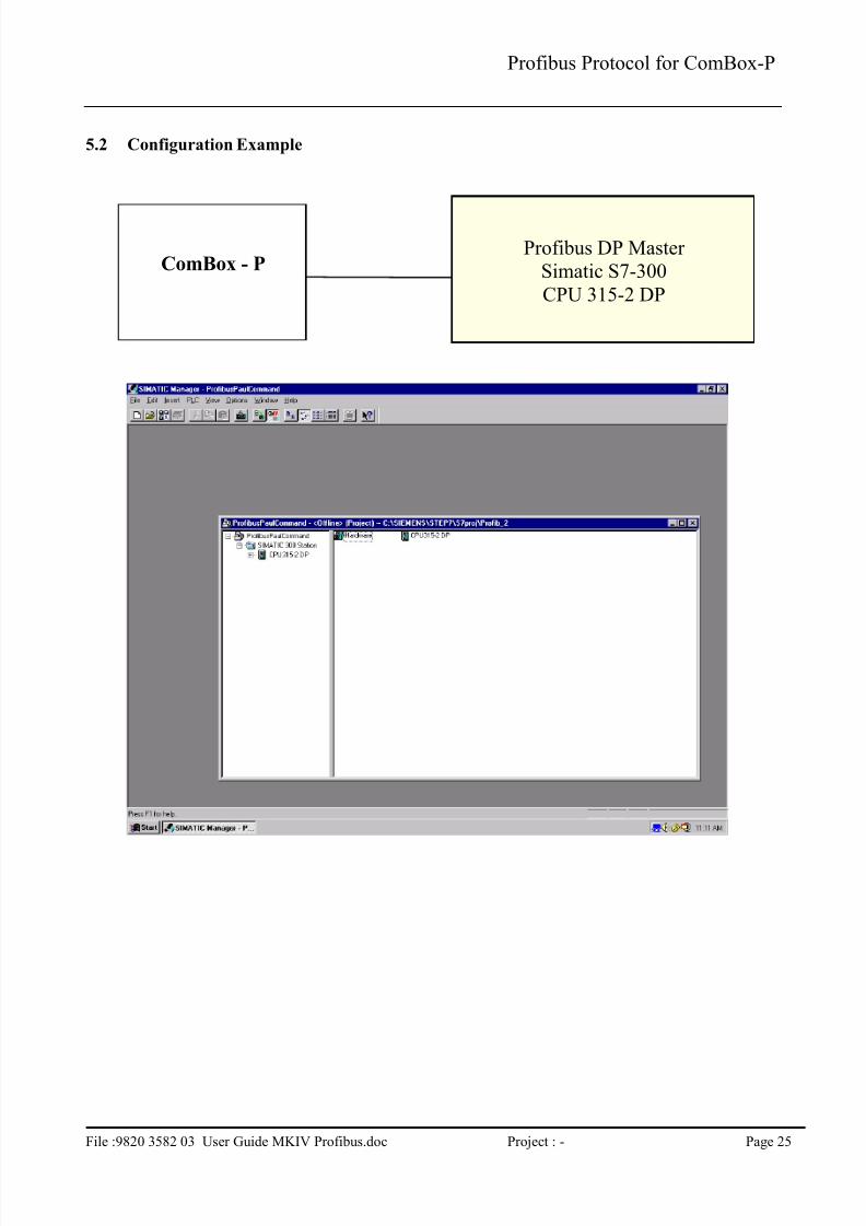
In order to setup a profibus connection to one or several of the compressors in this network, a special module as to beinserted in this network.
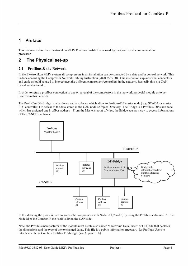
The Profi-Can DP-Bridge is a hardware and a software which allow to Profibus-DP master node ( e.g. SCADA or master
PLC controller ) to access to the data stored in the CAN node’s Object Directory. The Bridge is a Profibus-DP slave nodewhich has assigned one Profibus address. From the Master's point of view, the Bridge acts as a way to access informations
of the CANBUS network.
In this drawing the proxy is used to access the compressors with Node Id 1,2 and 3, by using the Profibus addresses 15. The
Node Id pf the Combox-P the itself is 20 on the CAN side.
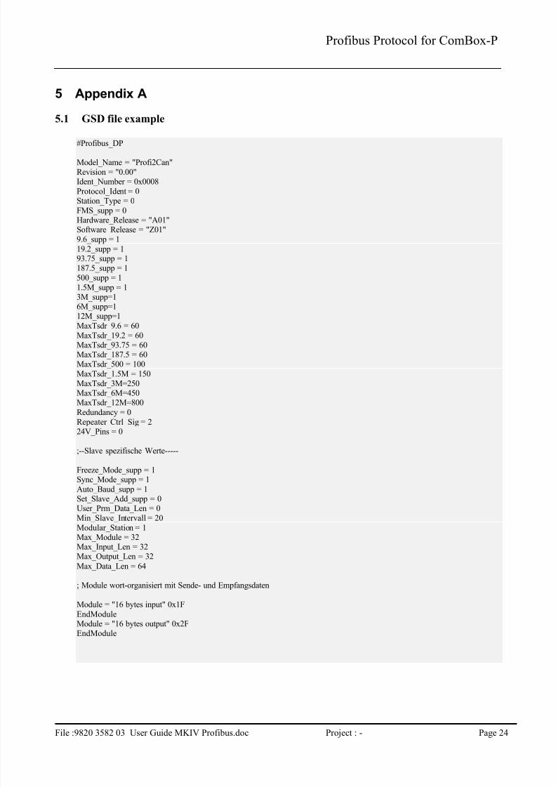
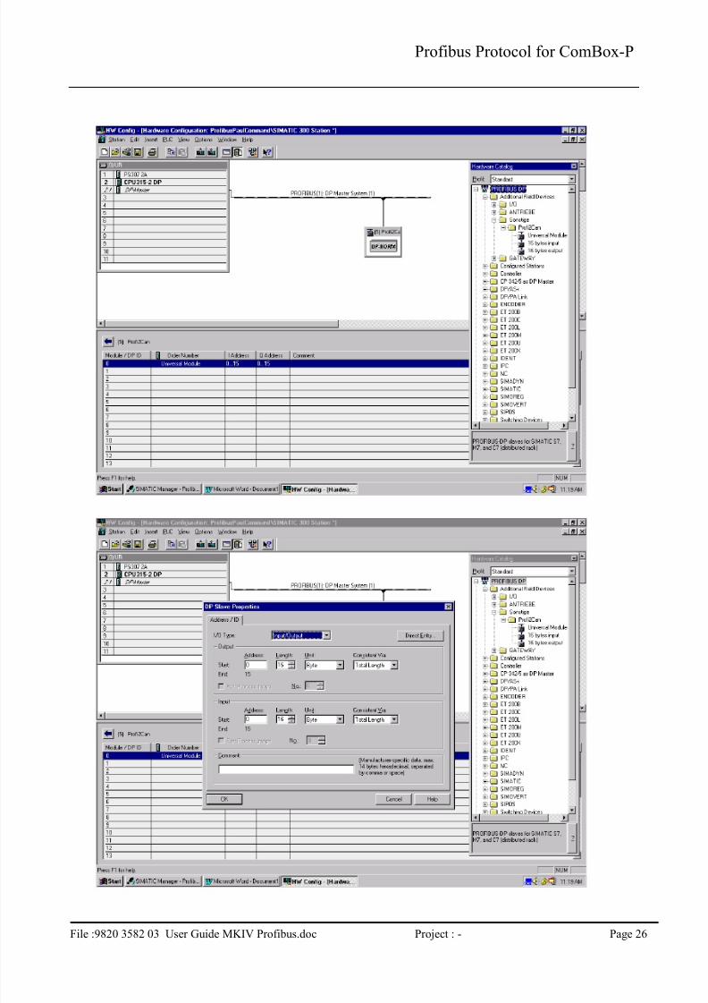
Note: the Profibus manufacturer of the module must create a so named “Electronic Data Sheet” or GSD file that declares
the dimensions and the type of the exchanged datas. This file is a public information necessary for Profibus Users to
interface with the Combox Profibus DP-bridge. (see Appendix A)
The profile is based on the standard Profibus-DP protocol, with following basic specifications:
DP-Slave on Siemens SPC3 Asic
RS485
Baudrate: 9.600 Kbaud to 12.000 Mbaud
Autobaud: supported
Freeze Mode: Not supported
Sync Mode: Not supported
Slave Node Address Change: not supported
Diagnostics : not supported
4 Profile definition
4.1 Master – Slave concept
The profile is based upon the master-slave principle. This means all communication is initiated by the master and a reply is
generated by the slave (ComBox-P).
All buffers should be full length consistent.
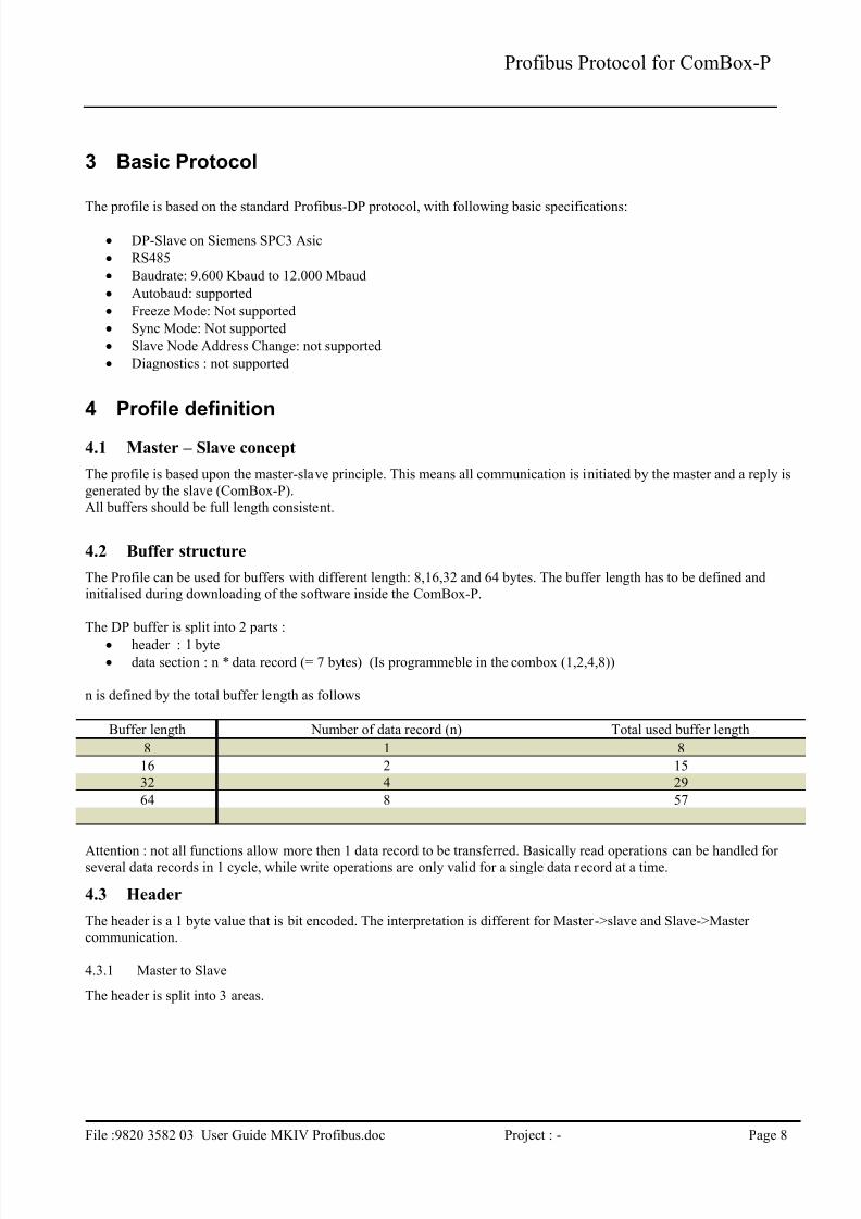
4.2 Buffer structure
The Profile can be used for buffers with different length: 8,16,32 and 64 bytes. The buffer length has to be defined and
initialised during downloading of the software inside the ComBox-P.
The DP buffer is split into 2 parts :
header : 1 byte data section : n * data record (= 7 bytes) (Is programmeble in the combox (1,2,4,8))
n is defined by the total buffer length as follows
Buffer length Number of data record (n) Total used buffer length
8 1 8
16 2 15
32 4 29
64 8 57
Attention : not all functions allow more then 1 data record to be transferred. Basically read operations can be handled for several data records in 1 cycle, while write operations are only valid for a single data record at a time.
4.3 Header
The header is a 1 byte value that is bit encoded. The interpretation is different for Master->slave and Slave->Master
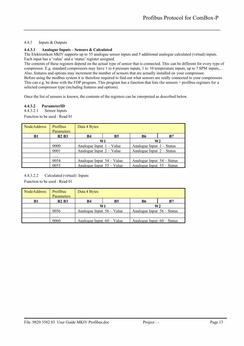
The Elektronikon MkIV supports up to 55 analogue sensor inputs and 5 additional analogue calculated (virtual) inputs.
Each input has a ‘value’ and a ‘status’ register assigned.The contents of these registers depend on the actual type of sensor that is connected. This can be different for every type of
compressor. E.g. standard compressors may have 1 to 4 pressure inputs, 1 to 10 temperature inputs, up to 7 SPM inputs,…
Also, features and options may increment the number of sensors that are actually installed on your compressor.
Before using the modbus system it is therefore required to find out what sensors are really connected to your compressors.
This can e.g. be done with the FDP program. This program has a function that lists the sensors + profibus registers for a
selected compressor type (including features and options).
Once the list of sensors is known, the contents of the registers can be interpreted as described below.
4.4.3.2 ParameterID
4.4.3.2.1 Sensor Inputs
Function to be used : Read 01
NodeAddress Profibus
Parameters
Data 4 Bytes
B1 B2 B3 B4 B5 B6 B7
W1 W2
0000 Analogue Input 1 – Value Analogue Input 1 – Status
0001 Analogue Input 2 – Value Analogue Input 2 – Status
…..
0054 Analogue Input 54 – Value Analogue Input 54 – Status
0055 Analogue Input 55 – Value Analogue Input 55 – Status
4.4.3.2.2 Calculated (virtual) Inputs
Function to be used : Read 01
NodeAddress Profibus
Parameters
Data 4 Bytes
B1 B2 B3 B4 B5 B6 B7
W1 W2
0056 Analogue Input 56 – Value Analogue Input 56 – Status
…..
0060 Analogue Input 60 – Value Analogue Input 60 – Status
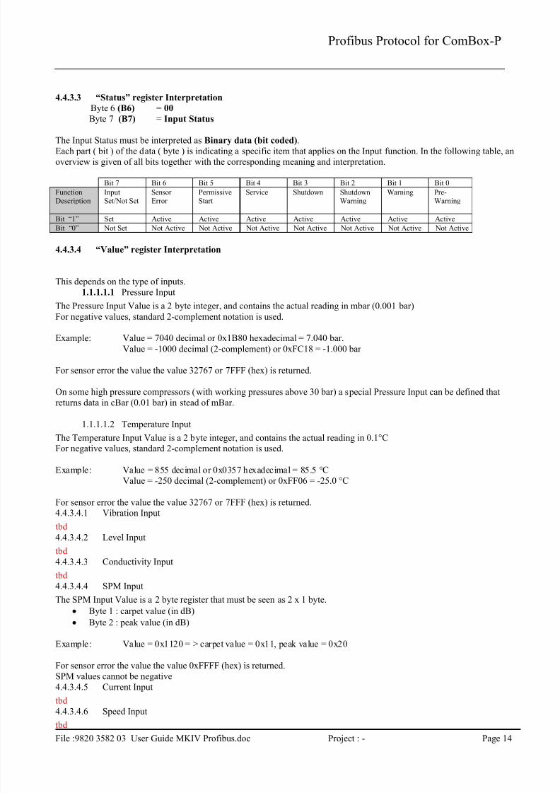
The Input Status must be interpreted as Binary data (bit coded).Each part ( bit ) of the data ( byte ) is indicating a specific item that applies on the Input function. In the following table, an
overview is given of all bits together with the corresponding meaning and interpretation.
Bit 7 Bit 6 Bit 5 Bit 4 Bit 3 Bit 2 Bit 1 Bit 0
Function
Description
Input
Set/Not Set
Sensor
Error
Permissive
Start
Service Shutdown Shutdown
Warning
Warning Pre-
Warning
Bit “1” Set Active Active Active Active Active Active Active
Bit “0” Not Set Not Active Not Active Not Active Not Active Not Active Not Active Not Active
4.4.3.4 “Value” register Interpretation
This depends on the type of inputs.
1.1.1.1.1 Pressure Input
The Pressure Input Value is a 2 byte integer, and contains the actual reading in mbar (0.001 bar)
For negative values, standard 2-complement notation is used.
Example: Value = 7040 decimal or 0x1B80 hexadecimal = 7.040 bar.
Value = -1000 decimal (2-complement) or 0xFC18 = -1.000 bar
For sensor error the value the value 32767 or 7FFF (hex) is returned.
On some high pressure compressors (with working pressures above 30 bar) a special Pressure Input can be defined that
returns data in cBar (0.01 bar) in stead of mBar.
1.1.1.1.2 Temperature Input
The Temperature Input Value is a 2 byte integer, and contains the actual reading in 0.1°CFor negative values, standard 2-complement notation is used.
Example: Value = 855 decimal or 0x0357 hexadecimal = 85.5 °C
Value = -250 decimal (2-complement) or 0xFF06 = -25.0 °C
For sensor error the value the value 32767 or 7FFF (hex) is returned.4.4.3.4.1 Vibration Input
tbd
4.4.3.4.2 Level Input
tbd4.4.3.4.3 Conductivity Input
tbd
4.4.3.4.4 SPM Input
The SPM Input Value is a 2 byte register that must be seen as 2 x 1 byte.
Byte 1 : carpet value (in dB)
Byte 2 : peak value (in dB)
Example: Value = 0x1120 = > carpet value = 0x11, peak value = 0x20
For sensor error the value the value 0xFFFF (hex) is returned.
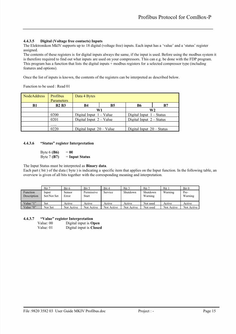
The Elektronikon MkIV supports up to 18 digital (voltage free) inputs. Each input has a ‘value’ and a ‘status’ register
assigned.The contents of these registers is for digital inputs always the same, if the input is used. Before using the modbus system it
is therefore required to find out what inputs are used on your compressors. This can e.g. be done with the FDP program.This program has a function that lists the digital inputs + modbus registers for a selected compressor type (including
features and options).
Once the list of inputs is known, the contents of the registers can be interpreted as described below.
Function to be used : Read 01
NodeAddress Profibus
Parameters
Data 4 Bytes
B1 B2 B3 B4 B5 B6 B7
W1 W2
0200 Digital Input 1 – Value Digital Input 1 – Status
0201 Digital Input 2 – Value Digital Input 2 – Status
…..
0220 Digital Input 20 – Value Digital Input 20 – Status
4.4.3.6 “Status” register Interpretation
Byte 6 (B6) = 00
Byte 7 (B7) = Input Status
The Input Status must be interpreted as Binary data.
Each part ( bit ) of the data ( byte ) is indicating a specific item that applies on the Input function. In the following table, an
overview is given of all bits together with the corresponding meaning and interpretation.
Bit 7 Bit 6 Bit 5 Bit 4 Bit 3 Bit 2 Bit 1 Bit 0
Function
Description
Input
Set/Not Set
Sensor
Error
Permissive
Start
Service Shutdown Shutdown
Warning
Warning Pre-
Warning
Value “1” Set Active Active Active Active Not used Active Active
Value “0” Not Set Not Active Not Active Not Active Not Active Not used Not Active Not Active
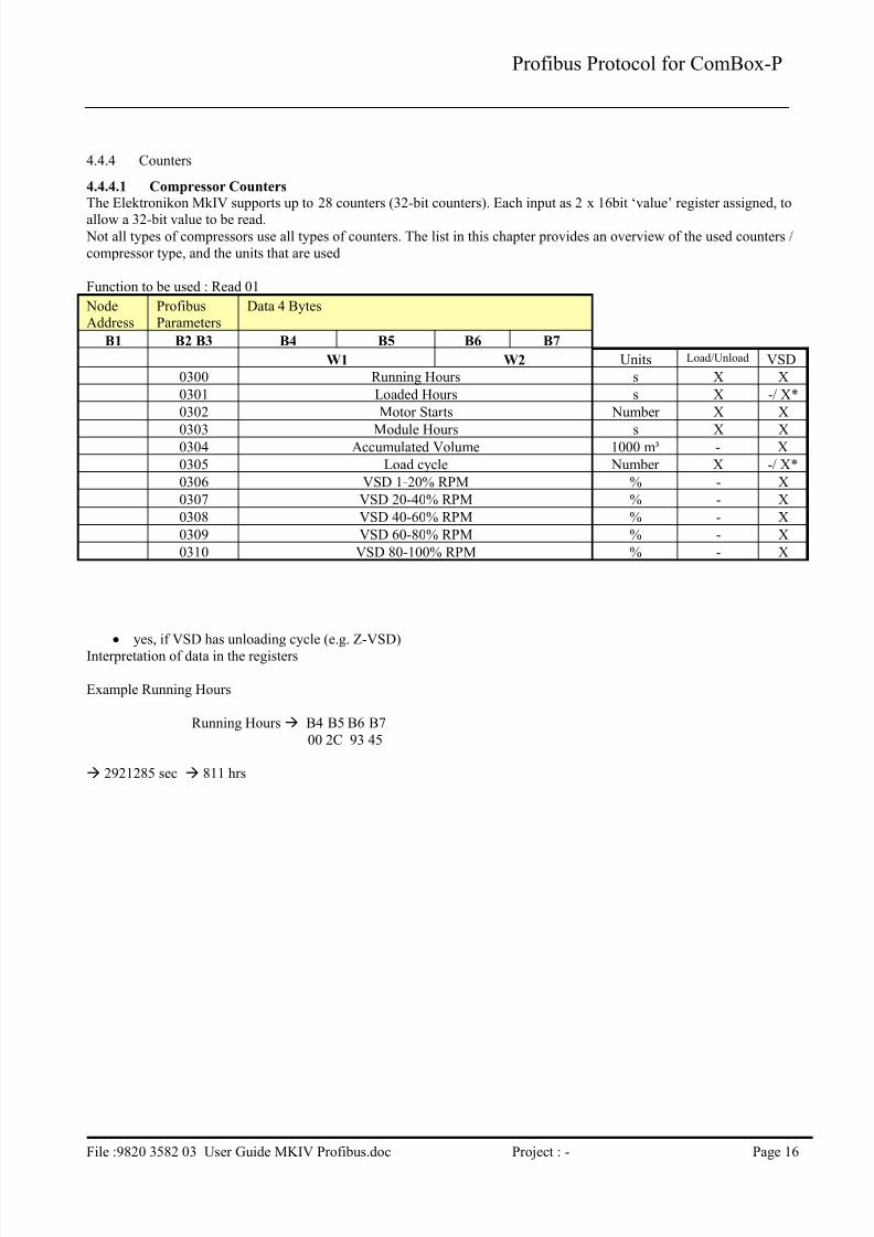
The Elektronikon MkIV supports up to 28 counters (32-bit counters). Each input as 2 x 16bit ‘value’ register assigned, to
allow a 32-bit value to be read. Not all types of compressors use all types of counters. The list in this chapter provides an overview of the used counters /
compressor type, and the units that are used
Function to be used : Read 01
NodeAddress
ProfibusParameters
Data 4 Bytes
B1 B2 B3 B4 B5 B6 B7
W1 W2 Units Load/Unload VSD
0300 Running Hours s X X
0301 Loaded Hours s X -/ X*
0302 Motor Starts Number X X
0303 Module Hours s X X0304 Accumulated Volume 1000 m³ - X
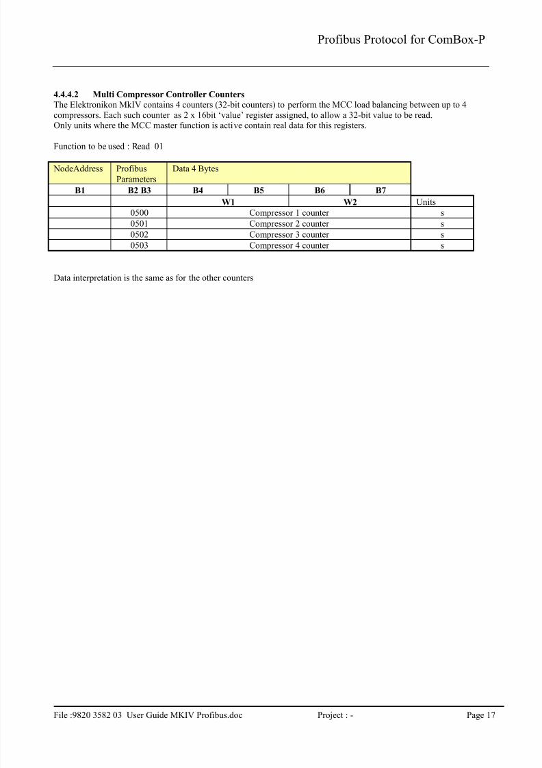
The Elektronikon MkIV contains 4 counters (32-bit counters) to perform the MCC load balancing between up to 4
compressors. Each such counter as 2 x 16bit ‘value’ register assigned, to allow a 32-bit value to be read.Only units where the MCC master function is active contain real data for this registers.
Function to be used : Read 01
NodeAddress Profibus
Parameters
Data 4 Bytes
B1 B2 B3 B4 B5 B6 B7
W1 W2 Units
0500 Compressor 1 counter s
0501 Compressor 2 counter s
0502 Compressor 3 counter s
0503 Compressor 4 counter s
Data interpretation is the same as for the other counters
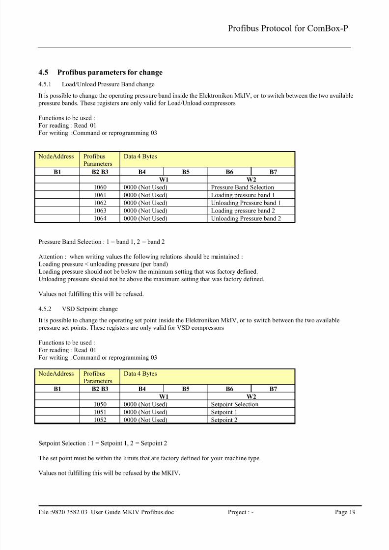
It is possible to change the operating pressure band inside the Elektronikon MkIV, or to switch between the two available pressure bands. These registers are only valid for Load/Unload compressors
Functions to be used :
For reading : Read 01
For writing :Command or reprogramming 03
NodeAddress Profibus
Parameters
Data 4 Bytes
B1 B2 B3 B4 B5 B6 B7
W1 W2
1060 0000 (Not Used) Pressure Band Selection
1061 0000 (Not Used) Loading pressure band 1
1062 0000 (Not Used) Unloading Pressure band 1
1063 0000 (Not Used) Loading pressure band 2
1064 0000 (Not Used) Unloading Pressure band 2
Pressure Band Selection : 1 = band 1, 2 = band 2
Attention : when writing values the following relations should be maintained :
Loading pressure < unloading pressure (per band)
Loading pressure should not be below the minimum setting that was factory defined.
Unloading pressure should not be above the maximum setting that was factory defined.
Values not fulfilling this will be refused.
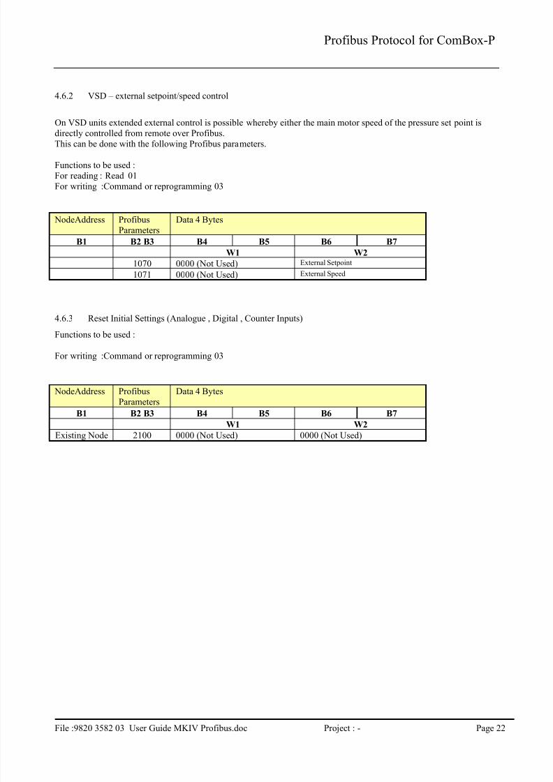
4.5.2 VSD Setpoint change
It is possible to change the operating set point inside the Elektronikon MkIV, or to switch between the two available
pressure set points. These registers are only valid for VSD compressors
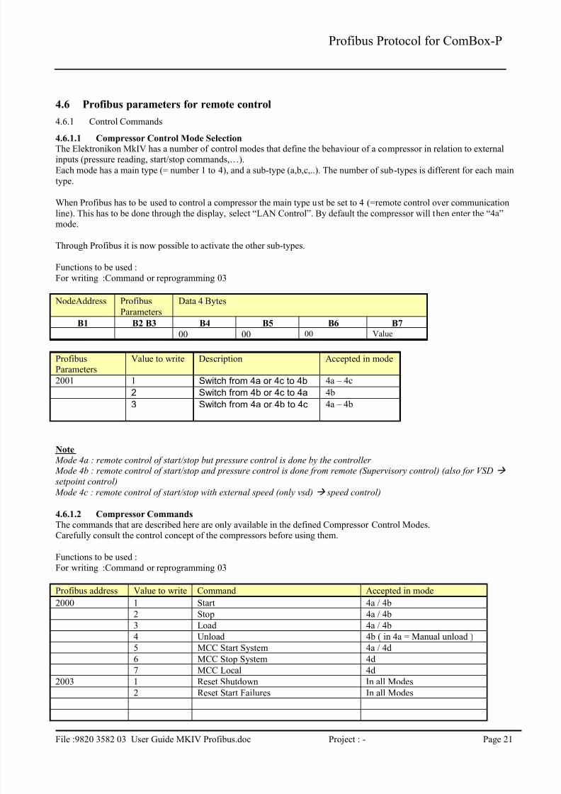
4.6.1.1 Compressor Control Mode SelectionThe Elektronikon MkIV has a number of control modes that define the behaviour of a compressor in relation to externalinputs (pressure reading, start/stop commands,…).
Each mode has a main type (= number 1 to 4), and a sub-type (a,b,c,..). The number of sub-types is different for each main
type.
When Profibus has to be used to control a compressor the main type ust be set to 4 (=remote control over communication
line). This has to be done through the display, select “LAN Control”. By default the compressor will then enter the “4a”mode.
Through Profibus it is now possible to activate the other sub-types.
Functions to be used :
For writing :Command or reprogramming 03
NodeAddress Profibus
Parameters
Data 4 Bytes
B1 B2 B3 B4 B5 B6 B7
00 00 00 Value
ProfibusParameters
Value to write Description Accepted in mode
2001 1 Switch from 4a or 4c to 4b 4a – 4c
2 Switch from 4b or 4c to 4a 4b
3 Switch from 4a or 4b to 4c 4a – 4b
Note
Mode 4a : remote control of start/stop but pressure control is done by the controller Mode 4b : remote control of start/stop and pressure control is done from remote (Supervisory control) (also for VSD
setpoint control)
Mode 4c : remote control of start/stop with external speed (only vsd) speed control)
4.6.1.2 Compressor Commands
The commands that are described here are only available in the defined Compressor Control Modes.Carefully consult the control concept of the compressors before using them.
Functions to be used :For writing :Command or reprogramming 03
Profibus address Value to write Command Accepted in mode