Prepared by PI Working Group PG1 “Passive Network Components” in Committee B “Technologies”.
The attention of adopters is directed to the possibility that compliance with or adoption of PI (PROFIBUS&PROFINET International) specifications may require use of an invention covered by patent rights. PI shall not be responsible for identifying patents for which a license may be required by any PI specification, or for conducting legal inquiries into the legal validity or scope of those patents that are brought to its attention. PI specifications are prospective and advisory only. Prospective users are responsible for protecting themselves against liability for infringement of patents.
NOTICE: The information contained in this document is subject to change without notice. The material in this document details a
PI specification in accordance with the license and notices set forth on this page. This document does not represent a commitment to implement any portion of this specification in any company's products.
WHILE THE INFORMATION IN THIS PUBLICATION IS BELIEVED TO BE ACCURATE, PI MAKES NO WARRANTY OF ANY KIND, EXPRESS OR IMPLIED, WITH REGARD TO THIS MATERIAL INCLUDING, BUT NOT LIMITED TO ANY WARRANTY OF TITLE OR OWNERSHIP, IMPLIED WARRANTY OF MERCHANTABILITY OR WARRANTY OF FITNESS FOR PARTICULAR PURPOSE OR USE.
In no event shall PI be liable for errors contained herein or for indirect, incidental, special, consequential, reliance or cover damages, including loss of profits, revenue, data or use, incurred by any user or any third party. Compliance with this specification does not absolve manufacturers of PROFIBUS or PROFINET equipment, from the requirements of safety and regulatory agencies (TÜV, BIA, UL, CSA, FCC, IEC, etc.).
PROFIBUS® and PROFINET® logos are registered trade marks. The use is restricted to members of PROFIBUS&PROFINET International. More detailed terms for the use can be found on the web page www.profibus.com/Downloads. Please select button "Presentations & logos".
In this specification the following key words (in bold text) will be used: may: indicates flexibility of choice with no implied preference. should: indicates flexibility of choice with a strongly preferred implementation. shall: indicates a mandatory requirement. Designers shall implement such
mandatory requirements to ensure interoperability and to claim conformance with this specification.
1 Management Summary – Purpose and Scope of the Document ................................... 5 2 List of Affected Patents / Certification .......................................................................... 5 3 Related Documents and References .............................................................................. 6 4 Definitions and Abbreviations ....................................................................................... 9 5 Balanced cabling with 2 or 4 pair-cabling ................................................................... 10 6 Characterisation of the Environmental Conditions in Production and Field Areas .. 10 7 Connectors and cables for PROFINET ......................................................................... 11 8 Procedure for a PROFINET Conformity Certificate ..................................................... 13 9 Connectors for PROFINET Data Cabling ..................................................................... 15
9.1 Connectors for Inside Environment (Balanced Cabling) ................................... 15 Introduction ............................................................................................. 15 9.1.1 Connector for Type C Cables and for Cabinet cord sets ....................... 16 9.1.2 RJ 45 Connector ...................................................................................... 18 9.1.3
9.2 Internal Device Connectivity for PROFINET Process devices ........................... 19 Applications ............................................................................................. 19 9.2.1 Connection terminal variations ............................................................... 19 9.2.2
Table 9.2.1-3: Contact and Wire Arrangement 2/4 pair ...................................................... 20 9.3 Connectors for Outside Environment (Balanced cabling) ................................. 22
Cord Sets for Balanced Type A/B Cabling .............................................. 54 12.1.1 Cord Sets for Balanced Type C Cabling ................................................. 54 12.1.2
12.2 Cabinet cord sets for balanced cabling.............................................................. 55 Qualification test for PROFINET cabinet cord sets ................................ 56 12.2.1 : PROFINET Cabinet cord set specification ........................................... 57 12.2.2
12.3 Cabinet cord sets for optical cabling ................................................................. 59 12.4 End-to-End Link assemblies for balanced cabling ............................................ 61
Procedures for measurement of the End-to-End link............................. 62 12.4.112.5 Bulkheads for Balanced Cabling ........................................................................ 62
The PROFINET bulkhead ......................................................................... 63 12.5.113 24 Volt Cabling ............................................................................................................. 64
13.1 Connectors for 24 Volt Cabling .......................................................................... 64 Colour Coding for 24 Volt connectors .................................................... 66 13.1.1 24 Volt Push Pull connector .................................................................... 67 13.1.2 M12 Power circular L-coded connector .................................................. 68 13.1.3
13.2 Cables for 24 Volt Cabling .................................................................................. 70 13.3 Cord sets for 24 Volt Cabling .............................................................................. 73
14 Connector for PROFINET Signal Cabling .................................................................... 73 14.1 Push Pull Signal connector ................................................................................ 73
Qualification Test for PROFINET Signal Cabling ................................... 74 14.1.115 Application specific Cabling and Interconnection Technology .................................. 74
15.1 Connector Definition according to AIDA Standard ............................................ 74 16 Connectors for 400 Volt Power Cabling ...................................................................... 75
Revision Log
Version Date Changes/History 1.8 TC2WG6 12-Dec-2002 First draft in PI review 1.96 TC2WG6 31-Aug-2006 Second draft; structure changed, new content 1.99 TC2WG6 05-Oct-2006 WG 2.00 TC2WG6 12-Mar-2007 PI Review finished / Change Requests included 2.01 TC2WG6 03-Mar-2011 First WG Draft (2 and 4 pair Cabling) 2.02 TC2WG6 14-Apr-11 WG 2.03 TC2WG6 14-Apr-11 WG Draft 2.04 TC2WG6 27-Apr-11 Type A,B cable (outer diameter: 9 mm) 2.05 TC2WG6 Editorial revision 2.06 TC2WG6 23-Mai-11 Version for WG meeting 2011-05-26 2.1 TC2WG6 26-Mai-11 WG Draft 2.9 TC2WG6 14-Jun-11 PI Review 3.00 TC2WG6 PI Review finished / Change Requests included 3.01 CB/PG1 15-Nov-11 Final for publishing 3.02 CB/PG1 20-Nov-13 Cabinet cord set specification; M 12 x-coded contact arrangement 3.1 CB/PG1 06-Mar-14 Push Pull Signal, LC Fibre Optic 4.00 CB/PG1 02-Feb-17 M12 L-coded +cable, M8 D-coded, Push Pull LC 4.10 CB/PG1 May 2018 Colour Coding of M12 L and PushPull
R cable for robotics applications added 4.11 CB/PG1 01-Oct-19 R Cable specification added
1 Management Summary – Purpose and Scope of the Document
Horizontal communication between automation and field equipment, as well as vertical communication between corporate management level and production, is guaranteed with PROFINET. This guideline describes the passive infrastructure of PROFINET Networks specified in the IEC 61918 and IEC 61784-5-3 inside and between the automation islands. In industrial applications networks with 2 pair and 4 pair cabling are required. This document describes techniques and components for 2 and 4 pair cabling. In addition the migration between 2 pair and 4 pair cabling is described. To fulfil industrial requirements, the industrial installation has to work in industrial environments. This PROFINET guideline describes connectors and cables. The wiring of PROFINET networks has to be realised under system aspects. Compatibility of PROFINET components is necessary to enable easy planning and installation. This Guideline describes the specification for:
• Connectors, cables, cordsets and other passive network components (e.g. Bulkheads) for
PROFINET Data (Optical Fibre and balanced cabling for PROFINET communication) • Connectors, cables and other passive network components (e.g. T-pieces) for PROFINET 24 Volt
power supply • Connectors and other passive network components (e.g. T-pieces) for PROFINET 400 Volt
Power distribution bus • Device Integration of PROFINET connectors • Test procedure for the End-to-End link
This Guideline describes the test specification for:
• Connectors, cables, cordsets and other passive network components (e.g. bulkhead) for PROFINET (optical fibre and balanced PROFINET communication)
This PROFINET guideline is intended to be used by: Manufacturers of PROFINET cables, connectors, devices and manufacturers of test equipment for PROFINET cabling.
2 List of Affected Patents / Certification
Attention is drawn to the possibility that some of the elements of this guideline may be the subject of patent rights as listed below. The PROFIBUS Nutzerorganisation e.V. (PNO) shall not be held responsible for identifying any or all such patent rights. Relevant patents are only those which have an impact on mating compatibility. Affected Patents: The patent WO 9942877 from company Reichle & De-Massari AG concerns the mating face of the SCRJ FO connector. PROFIBUS&PROFINET International does not guarantee the completeness of the affectted patents. For all other connectors the CBPG1 no information is available concerning patents on the mating face. Passive components are not certified by PI, but the vendor shall give a declaration of conformity to this Guideline.
DIN EN 61076-2-109:2014, Connectors for electronic equipment - Product requirements - Part 2-109: Circular connectors - Detail specification for connectors M12 x 1 with screw-locking, for data transmissions with frequencies up to 500 MHz
EN 50377-6-1:2003, Connector sets and interconnect components to be used in optical fibre communication systems, Product specifications, Part 6-1: Type SC-RJ terminated on IEC
IEC 60050-series: International Electrotechnical Vocabulary
IEC 60060–1: High-voltage test techniques. Part 1: General definitions and test requirements
IEC 60079-11: Explosive atmospheres - Part 11: Equipment protection by intrinsic safety "i"
IEC 60079-14: Explosive atmospheres – Part 14: Electrical installations design, selection and erection
IEC 60189-1: Low-frequency cables and wires with PVC insulation and PVC sheath. Part 1: General test and measuring methods
IEC 60332-1-series: Tests on electrical and optical fibre cables under fire conditions
IEC 60364-1: Low-voltage electrical installations - Part 1: Fundamental principles, assessment of general characteristics, definitions
IEC 60364-4-41: Low-voltage electrical installations - Part 4-41: Protection for safety - Protection against electric shock
IEC 60364-4-42: Low-voltage electrical installations - Part 4-42: Protection for safety - Protection against thermal effects
IEC 60364-4-44: Low-voltage electrical installations - Part 4-44: Protection for safety - Protection against voltage disturbances and electromagnetic disturbances
IEC 60364-5-54: Electrical installations of buildings - Part 5-54: Selection and erection of electrical equipment – Earthing arrangements, protective conductors and protective bonding conductors.
IEC 60512-6-3-series:: Connectors for electronic equipment - Tests and measurements - Part 6-3: Dynamic stress tests - Test 6c: Shock
IEC 60512-6-4: Connectors for electronic equipment - Tests and measurements - Part 6-4: Dynamic stress tests - Test 6d: Vibration: sinusoidal
IEC 60603-7-series: Connectors for electronic equipment - Detail specification for 8-way, shielded, free and fixed connectors, for data transmissions
IEC 60603-7: Connectors for electronic equipment - Part 7: Detail specification for 8-way, unshielded, free and fixed connectors
IEC 60664-1: Insulation coordination for equipment within low-voltage systems - Part 1: Principles, requirements and tests
IEC 60793-2-series:, Optical fibres - Part 2, specification of A1a and A1b multimode fibre
IEC 60793-2-50: Optical fibres – Part 2-50: Product specifications – Sectional specification for class B single–mode fibres
IEC 60794-1-series: Optical fibre cables –: Generic specification – General
IEC 60811-201: Electric and optical fibre cables - Test methods for non-metallic materials - Part 201: General tests - Measurement of insulation
IEC 60811-401: Electric and optical fibre cables - Test methods for non-metallic materials - Part 401: Miscellaneous tests - Thermal ageing methods - Ageing in an air oven
IEC 60811-508: Electric and optical fibre cables - Test methods for non-metallic materials - Part 508: Mechanical tests - Pressure test at high temperature for insulation and sheaths
IEC 60227-2: Polyvinyl chloride insulated cables of rated voltages up to and including 450/750 V Part 2: Test methods
IEC 60228: Conductors of insulated cables
IEC 60874-14series: Connectors for optical fibres and cables – all parts 14-x: Detail specification for fibre optic connector type SC
IEC 60950-1: Information technology equipment -Safety- Part 1: General requirements
IEC 60950-1-am1: Amendment 1 - Information technology equipment - Safety - Part 1: General requirements
IEC 60950-21: Information technology equipment -Safety- Part 21: Remote power feeding.
IEC 61000-4 series: Electromagnetic compatibility: EMC, Testing and measurement techniques Parts 4-x ISO 23570-3: Industrial automation systems and integration — Distributed installation
IEC 61000-6-4 am1: Electromagnetic compatibility: EMC) - Part 6-4: Generic standards - Emission standard for industrial environments
IEC 61010-1: Safety requirements for electrical equipment for measurement, control, and laboratory use - Part 1: General requirements
IEC 61076-2-101: Connectors for electronic equipment - Product requirements - Part 2-101: Circular connectors - Detail specification for M12 connectors with screw-locking
IEC 61076-2-107: Connectors for electronic equipment – Product requirements – Part 2 107: Detail specification for circular hybrid connectors M12 with electrical and fibre-optical contacts with screw-locking
IEC 61076-3-106: Connectors for electronic equipment - Product requirements - Part 3-106: Rectangular connectors - Detail specification for protective housings for use with 8-way shielded and unshielded connectors for industrial environments incorporating the IEC
IEC 61076-3-117: Connectors for electronic equipment – Product requirements – Part 3 117: Rectangular connectors – Detail specification for protective housings for use with 8-way shielded and unshielded connectors for industrial environments incorporating IEC 60603-7 series interface – Variant 14 related to IEC 61076-3-106 – Push-pull coupling
IEC 61131-2: Programmable controllers - Part 2: Equipment requirements and tests
IEC 61156-2: Multicore and symmetrical pair/quad cables for digital communications - Part 2: Symmetrical pair/quad cables with transmission characteristics up to 100 MHz - Horizontal floor wiring - Sectional specification
IEC 61156-3: Multicore and symmetrical pair/quad cables for digital communications – Part 3: Work area wiring; Sectional specification
IEC 61156-6: Multicore and symmetrical pair/quad cables for digital communications - Part 6: Symmetrical pair/quad cables with transmission characteristics up to 1 000 MHz - Work area wiring - Sectional specific
IEC 61158-2: Digital data communications for measurement and control - Fieldbus for use in
IEC 61300-series Fibre optic interconnecting devices and passive components - Basic test and measurement procedures
IEC 61326-1: Electrical equipment for measurement, control and laboratory use - EMC requirements - Part 1: General requirements
IEC 61326-3-1-series: Electrical equipment for measurement, control and laboratory use - EMC requirements - Part 3-1: Immunity requirements for safety-related systems and for equipment intended to perform safety-related functions: functional safety - General industrial applications
IEC 61753-series: Fibre optic interconnecting devices and passive components performance standard
IEC 61754-24: Fibre optic connector interfaces, - Part 24: Type SC-RJ connector family
IEC 61754-24-11: Fibre optic interconnecting devices and passive components - Fibre optic connector interfaces - Part 24-11: Type SC-RJ connectors with protective housings based on IEC
IEC 61784-1: Industrial communication networks - Profiles - Part 1: Fieldbus profiles industrial control systems physical layer.
IEC 61784-2: Industrial communication networks - Profiles - Part 2: Additional fieldbus profiles for real-time networks based on ISO/IEC
IEC 61784-3: Industrial communication networks - Profiles - Part 3: Functional safety fieldbuses - General rules and profile definitions
IEC 61784-5-3: Industrial communication networks - Profiles - Part 5-3: Installation of fieldbuses - Installation profiles for CPF 3
IEC 61918: Industrial communication networks - Installation of communication networks in industrial premises
IEC 61935-1: Specification for the testing of balanced and coaxial information technology cabling – Part 1: Installed balanced cabling as specified in ISO/IEC 11801 and related Standards
IEC 61935-2: Specification for the testing of balanced and coaxial information technology cabling - Part 2: Cords as specified in ISO/IEC 11801 and related standards
IEC 61984: Connectors - Safety requirements and tests
IEC61156-5: Multicore and symmetrical pair/quad cables for digital communications – Part 5: Symmetrical pair/quad cables with transmission characteristics up to 1 000 MHz – Horizontal floor wiring – Sectional specification
IEC61754-20: Fibre optic connector interfaces – Part 20: Type LC connector family
IEC61754-24-11: Fibre optic interconnecting devices and passive components - Fibre optic connector interfaces - Part 24-11: Type SC-RJ connectors with protective housings based on IEC 61076-3-117
ISO 23570-3: Industrial automation systems and integration — Distributed installation in industrial applications — Part 3: Power distribution bus
ISO/IEC 11801-series::20 Information technology –Generic cabling for customer premises
ISO/IEC 14763-2: Information technology – Implementation and operation of customer premises cabling – Part 2: Planning and installation.
ISO/IEC 24702: Information technology - Generic cabling- Industrial premises
ISO/IEC 8802.3: Information technology—Telecommunications and information exchange between systems—Local and metropolitan area networks—Specific requirements—Part 3: Carrier sense multiple access with collision detection: CSMA/CD access method and physical layer specifications
IEC61076-3-101: Connectors with assessed quality, for use in d.c., low-frequency analogue and in digital high-speed data applications - Part 3: Rectangular connectors
IEC 61076-2-111: Connectors for electronic equipment - Product requirements - Part 2-111: Circular connectors - Detail specification for power connectors with M12 screw-l
IEC 61076-2-114: Circular connectors – Detail specification for data and power connectors with M8 screw-locking
IEC/PAS 61076-3-119: Connectors for electronic equipment - Product requirements - Part 3-119: Rectangular connectors - Detail specification for unshielded, free and fixed 10 way connectors with push-pull coupling for industrial environments with frequencies up to 100 MHz
IEC 61076-3-123: Rectangular connector. Detail specification for hybrid connectors for industrial environments, for power supply and fibre optic data transmission, with push-pull locking
PAS IEC 61076-3-series: Rectangular connectors. Detail specification for power connectors for industrial environments with Push-Pull locking
DIS ISO/IEC 14764-3:2017: Information Technology - Implementation and Operation of Customer Premises Cabling – Part 4: Measurement of End-To-End-Link.
IEC 61918: Industrial communication networks – Installation of communication networks in industrial premises
IEC 61784-5-3: Industrial communication networks – Profiles – Part 5-3: Installation of fieldbuses – Installation profiles for CPF 3
IEC 60352-4 Solderless connections - Part 4: Solderless non-accessible insulation displacement connections - General requirements, test methods and practical guidance
IEC 60999-1: Connecting devices – Electrical copper conductors – Safety requirements for screw-type and screwless-type clamping units – Part 1: General requirements and particular requirements for clamping units for conductors from 0,2 mm2 up to 35 mm2 (included)
4 Definitions and Abbreviations
For definitions and abbreviations see IEC 61918 and IEC 61784-5-3
The decision for 2 or 4 pair cabling is depending on the application. Decision criteria can be as followed: 2 pair-cabling 4 pair-cabling Cable design 2 pair-cabling shall be realised
as one star-quad or as 2 twisted pair design
4 pair-cabling shall be realised as two star-quad or as 4 twisted pair design
Vendor declaration Yes Yes Devices in the network PROFINET devices PROFINET devices and also
other IT devices Max. Channel length 100 m 100 m Component approach without network calculation applicable
Yes Yes
Field of application Specialized and optimized for defined PROFINET automation tasks
Universal use of a PROFINET network for PROFINET and other Ethernet applications, as already described in the planning guide.
Table 5.-1: Decision criteria for 2 or 4 pair cabling
In a PROFINET End-to-End link the transition from a 4 pair balanced cabling into a 2 pair balanced cabling is allowed. Table 9.2.1-3 shows the required contact arrangement.
6 Characterisation of the Environmental Conditions in Production and Field Areas
The environmental conditions and the PROFINET installation classes are defined in IEC 61784-5-3. The following text of this clause is only an informative abstract. Standard market components for data cabling (cables, plugs, switches etc.) were generally developed for operation in office-type environments. The office environment is covered by existing standards and is not taken into consideration here. The special environmental conditions in production and field areas call for specially enhanced and rugged components. Because the same high demands do not exist in all areas in the industrial sector, differentiation has to be made between "inside" and "outside" protected areas from a technical point of view:
• "Inside" refers to the environment found in control stations, electronic rooms or inside switch cabinets.
• "Outside" refers to higher demands with regard to temperature, dust, moisture, vibration etc.
as found when used directly at the field level. "Inside" and "Outside" do not describe different places in the machine. The only difference is the housing of the electronic equipment. Table 6.-1 provides a comparison of the general environmental conditions for the passive PROFINET connection system (cable and plug connection) in the two areas.
IEC 60512-6-3, test 6c 20 g / 11 ms 3 per axis in both directions
IEC 60512-6-3, test 6c 50 g / 11 ms 3 per axis in both directions
Vibration 10-500 Hz
IEC 60512-6-4, test 6d 0.35 mm or 5g
IEC 60512-6-4, test 6d 0.35 mm or 5g
Ingress
IP Protection class IP20 IP65 and IP67
Climatic
Ambient temperature 0° C to +70° C b) -20° C to +70° C b)
Electromagnetic
Transfer Impedance See components selection
a) Bump: the repetitive nature of the shock experienced by the channel shall be taken into account.
b) An additional heating by POE has to be considered by the user.
Table 6.-1: General Environmental Requirements of passive PROFINET Connection Systems (informative chart from IEC 61784-5-3: Edition 4)
7 Connectors and cables for PROFINET
The PROFINET philosophy is to unify the connectors for a safe and easy installation. In order to realise this, only the listed connectors shall be used for PROFINET networks. The use of these cables and connectors represent a matched system with interoperability. The connectors can be part of:
• Switch cabinet • Device • Cabling between devices • Connections within a channel • Controller • Industrial Outlet • Network Component • Sensor, Actuator • Drive, Motor • Coupling • …
The listed connectors are the specified PROFINET solutions. Other connectors shall not be used for PROFINET applications. Vendors only can declare for the listed connectors that fulfil the PROFINET specification a PROFINET vendor conformity declaration.
The integration of the 24 Volt power supply is referred as:
• PROFINET 24 Volt connectors and cabling • PROFINET Hybrid connector and cabling
The integration of the signals is referred as:
• PROFINET Signal connector and cabling The listed connector is a preferred PROFINET solution conforming to AIDA requirements.
The integration of the 400 Volt power supply is referred as:
• PROFINET 400 Volt connector and cabling
PROFINET refers to the Power distribution bus standardised in ISO 23570-3. Other connectors can be used for special applications.
The conformity testing is only relevant for the PROFINET data connectors and cabling.
Connectors and cables shall fulfil the requirements and standards described in this guideline. To ensure the compatibility of cables and connectors under the PROFINET system, the cables and connectors shall be tested.
The Conformity certificate guarantees that the components have been tested as specified. All tests refer to the inside and outside requirements specified in this guideline.
The product vendors shall issue a conformity certificate through the following procedure.
Figure 8-1: Procedure for PROFINET Components, except connectors
The vendor who issues the conformity certificate takes responsibility for the:
• listed cables and connectors or harnessed cables
• performing the test as specified in this guideline
• granting of the conformity certificate
The declaration can be issued unilaterally or bilaterally (e.g. from the cable and/or the connector vendor or the harness maker). Conformity testing is a requirement of PROFINET labelling of the products described in this guideline.
1)RJ-45 pinning compatibility applies only to the pins themselves. For full plug-in compatibility, the shape of the casing of industrial connectors shall also be taken into account. The specified RJ 45 receptacle (Jack) for“Outside” applications has to be mating compatible with the RJ 45 Plug, in accordance with IEC 60 603-7.
2) 2pair or 1 quad 3) 4pair or 2 quad 4) If cables other than AWG 22/7 are used, the conformance to the IDC of the connector is mandatory. 5) As defined by IEC 61984,clause 3.22 6) Mating and Unmating under load (e.g. PoE) not permitted
Table 9.1.1-1: Plug Connector Specifications
Connector for Type C Cables and for Cabinet cord sets 9.1.2
Connectors, which are optimised for the use of type C cable are permitted. These connectors can be matched to the cable in the following parameters:
All other requirements in Table 10-1: Plug Connector Specifications are not altered. The restricted use of these connectors shall be mentioned in the vendor declaration.
For type C cables the component approach is not supported.
Also connectors, which are harnessed in cabinet cords, can be matched in these parameters. There is no vendor declaration for connectors harnessed in the cabinet cord set.
9.1.2.1 Contact arrangement 2pairs The contact arrangement of the connectors and the colour coding of the cable is specified as follows:
Signal Function Wire Colours Contact Assignment
RJ-45 TD + Transmit Data + Yellow 1 TD - Transmit Data - Orange 2 RD + Receive Data + White 3 RD - Receive Data - Blue 6
Table 9.1.2-1: Contact and Wire Assignment 2pairs
The selected contact assignment of the RJ45 is compatible with the Ethernet standard, i.e. compatible with ISO/IEC 8802-3. Four contacts are mandatory for PROFINET, a RJ 45 with eight contacts is also covered by this specification.
Only devices which are designed for use within a protected environment (e.g. Environment Inside) shall be designed with an unprotected RJ45 connector.
9.1.2.2 Contact arrangement 4pairs The contact arrangement of the connectors and the colour coding of the cable is specified as follows:
Function 2 pair
Wire Colours Function 4 pair Wire Colours T568B
Contact Assignment RJ-45
TD + Yellow TD/RD 1
White/Green 3 TD - Orange Green 6 RD + White TD/RD 2
White/Orange 1
RD - Blue Orange 2 TD/RD 3 White/Blue 5 Blue 4 TD/RD 4
RD - Blue Green 2 TD/RD 3 White/Blue 5 Blue 4 TD/RD 4
White/Brown 7
Brown 8
Table 9.1.2-2: Contact and Wire Assignment 4pairs The selected contact assignment of the RJ45 is compatible with the Ethernet standard, i.e. compatible with ISO/IEC 8802-3 and TIA 568 C0 T Figure T568Bor Figure T568A.
Only devices which are designed for use within a protected environment (e.g. Environment Inside) shall be designed with an unprotected RJ45 connector.
RJ 45 Connector 9.1.3 Selection of RJ45 plug connector products shall comply with the criteria for industrial machinery and equipment. The use of plug connectors with altered technical specifications (for example dielectric strength or connecting system) in comparison with those for office use is stipulated.
Figure 9.1.3-1: Examples of RJ45 Plugs in IP20 with Industrial Performance
9.1.3.1 Qualification Test for Copper Connectors (RJ45 IP20 Connectors) The Qualification Test shall be performed in accordance with the following standards: IEC 60603-7 mechanical structure of RJ45 IEC 60603-7-1 introduction of shielding to RJ45 IEC 60603-7-3 Connectors for electronic equipment - Part 7-3: Detail specification for 8-way, shielded, free and fixed connectors, for data transmissions with frequencies up to 100 MHz IEC 60512-1-100, Connectors for electronic equipment – Tests and measurements – Part 1-100: General – Applicable publications IEC 60352-4 Solderless connections - Part 4: Solderless non-accessible insulation displacement connections - General requirements, test methods and practical guidance Additional test parameters are described in the IEC 61784-5-3. The plug for Inside Environment shall be pluggable to the jack in the protective housing specified in 9.3.2 to ensure reverse compatibility. An unprotected plug, which does not fulfil industrial requirements, can be used exceptionally as part of diagnosis or commissioning.
9.2 Internal Device Connectivity for PROFINET Process devices Process devices with a PROFINET connection are used in a variety of applications. The interface must meet the transfer-related requirements for PROFINET. These include the properties defined by PROFINET for a connection terminal. In addition to the PROFINET requirements, there are the requirements for the specific application in the process automation environment. If the requirements (e.g. Atex) are stricter than the PROFINET requirements, they should take priority. These application-specific requirements are not defined in the PROFINET guidelines.
Figure 9.2-1: Diagram of interaction between PROFINET requirements and application requirements.
Applications 9.2.1
The fixed connection is used for device connectivity inside field devices in process automation. The PROFINET connection in PA devices consists of the terminal used in the device in combination with the areas of the device designed for the cable connection, plus the shield connection and a suitable strain relief mechanism (e.g. cable gland). The terminal is described as a PROFINET-compliant component and PROFINET compliance is guaranteed by means of a manufacturer declaration. Guidelines are defined for the device connection. Only the combination of a PROFINET-compliant terminal and a shield connection designed in accordance with the guidelines guarantees a PROFINET-compliant connection for which the manufacturer of the device takes responsibility.
Connection terminal variations 9.2.2
There are two variants of the PROFINET connection terminal:
• PCB terminal block inside the device with direct connection to the PROFINET cable (example 2 pair).
• Connection terminal block inside a device for connection of internal and external PROFINET cables (example 2 pair).
9.2.2.1 PROFINET requirements for the connection terminals The contact arrangement of the termination and the colour coding of the cable is specified as follows:
Function 2 pair
Wire Colours Function 4 pair Wire Colours T568A
Wire Colours T568B
Terminal Block 2pair/4pair
TD + Yellow TD/RD 1
White/Orange White/Green 3 TD - Orange Orange Green 4 RD + White TD/RD 2
White/Green White/Orange 1
RD - Blue Green Orange 2 TD/RD 3 White/Blue White/Blue 7 Blue Blue 8 TD/RD 4
White/Brown White/Brown 5
Brown Brown 6
Table 9.2.1-3: Contact and Wire Arrangement 2/4 pair
Shielding / EMC and mechanical design (properties of PROFINET-compliant device connection)
Requirement Comment: The position and execution of the shield connection is defined in the device design. The electric parameters of the shield connection must comply with ISO/IEC 11801-1.
The device manufacturer is responsible for a clean shield connection. It defines "Met by Design"
The device must be fitted with a strain relief appropriate to the application.
The strain relief must be designed such that the requirements of the shield connection are complied with
The shield connection must be tailored to the balanced PROFINET 2/4 pair cable specified.
Table 9.2.2-1: Shielding / EMC Ethernet transfer (property of PROFINET-compliant terminal) Requirement Comment: Component requirement as per Category 5 in accordance with ISO IEC 11801-series (Connecting hardware)
The electrical approval of the transfer parameters is in analogy as a "mated pair". (Plug-in connector)
PROFINET cable with 2/4 pair is implemented in line with PROFINET Cabling and Interconnection Technology Guideline Balanced 2/4 pair Cables (Type A,B,C).
Additional contacts for further I/Os and power supply are not defined
Identification of contact points with known PROFINET cable colour assignment
See PROFINET Cabling and Interconnection Technology Guideline Chapter: Balanced 2/4 pair Cables (Type A,B,C)
A transfer of POE plus in accordance with IEEE 802.3at-2009 is required.
Additional heating as a result of POE plus me considered by the user
Voltage proof Conditions: IEC 60512, Test 4a, Method A. Standard atmospheric conditions. 1 000 V rms, contact-to-contact. 1 500 V rms, contact to shield.
The contact-to-contact test must be evidenced by the terminal manufacturer If applicable, the contact to shield test must be evidenced by the device manufacturer.
The requirements of IEC 60664-1 (insulation coordination) must be taken into consideration
Table 9.2.2-2: Ethernet transfer Mechanical, electrical and climatic requirements (property of PROFINET-compliant terminal) Requirement Comment: Shock and vibration Requirements for contact point in accordance with IEC 60512-6-3, Test 6c / 50 g / 11 ms / 3 per axis in both directions Vibration: IEC 60512-6-4, test 6d 0.35 mm or 5g
Referenced from PROFINET Interconnection Guideline Table 6. 1: General Environmental Requirements of passive PROFINET Connection Systems (informative chart from IEC 61784-5-3
Outer Cable Diameter 5,5 mm to 8,0 mm 5,5 mm to 9,0 mm 6,0 mm to 12,0 mm Wire Cross
Section Data
Power AWG 22 AWG 22 to AWG 24 AWG 22
1,5 mm² to 2,5 mm²
Wire Diameter Data
1,4 to 1,6 mm 1,0 to 1,6 mm 1,4 to 1,6 mm
Wire Construction Solid / Stranded Transmission Performance ISO/IEC 11801 Edition 2.0 Amendment 2, Class D
at least Category 5 Category (min.) ISO/IEC 11801 Edition 2.0 Connector Category 5
Shielding Yes Cable Strain Relief IEC 61984
Mating Cycles min. 50 Protection Class Pollution Degree
Shock Vibration
Operating Temperature Range
see Table 6-1 "Outside enclosure"
1) RJ-45 pinning compatibility applies only to the pins themselves. For full plug-in compatibility, the shape of the casing of industrial connectors shall also be taken into account. The specified RJ 45 receptacle (Jack) for “Outside” applications has to be mating compatible with the RJ 45 Plug, in accordance with IEC 60 603-7. 2) As defined by IEC 61984,clause 3.22
Table 9.2.1-1: Plug Connector Specifications
9.3.1.1 Contact arrangement 2 pair The contact arrangement of the connectors and the colour coding of the cable is specified as follows:
Table 9.2.1-2: Contact and Wire Assignment 2 pair The selected contact assignment of the RJ45 is compatible with the Ethernet standard, i.e. compatible with ISO/IEC 8802-3. Four contacts are mandatory for PROFINET, a RJ 45 with eight contacts is also covered by this specification. Only devices which are designed for use within a protected environment (e.g. Environment Inside) shall be designed with an unprotected RJ45 connector.
9.3.1.2 Contact arrangement 4 pair The contact arrangement of the connectors and the colour coding of the cable is specified as follows:
Function
Wire Colours T568A
Wire Colours T568B
Contact Assignment
RJ-45
Contact Assignment M12-4 pair
TD/RD 1
White/Orange White/Green 3 3 Orange Green 6 4
TD/RD 2
White/Green White/Orange 1 1 Green Orange 2 2
TD/RD 3 White/Blue White/Blue 5 7 Blue Blue 4 8
TD/RD 4
White/Brown White/Brown 7 5 Brown Brown 8 6
Table 9.2.1-3: Contact and Wire Arrangement 4pairs The selected contact assignment of the RJ45 is compatible with the Ethernet standard, i.e. compatible with ISO/IEC 8802-3 and TIA 568 C0 T Figure T568B or Figure T568A . Only devices which are designed for use within a protected environment (e.g. Environment Inside) shall be equipped with an unprotected RJ45 connector.
The selected contact assignment of the RJ45 is compatible with the Ethernet standard, i.e. compatible with ISO/IEC 8802-3. For IP65/67 field devices either a RJ45 or a M12-based solution is possible, depending on the application.
RJ45 PushPull Connector 9.3.2 Standardised RJ45-compatible IP67-plug connectors shall be used and the protective housing is described in the following standard: IEC 61076-3-117
Figure 9.2.2-1: Examples of IP67 PushPull Connector
9.3.2.1 Qualification Test for Copper Connectors (RJ 45 Based IP 67 Connectors)
The Qualification Test shall be performed in accordance with the following standards: IEC 61076-3-117 IEC 60603-7 mechanical structure of RJ45 IEC 60603-7-1 introduction of shielding to RJ45 IEC 60603-7-3 Connectors for electronic equipment - Part 7-3: Detail specification for 8-way, shielded, free and fixed connectors, for data transmissions with frequencies up to 100 MHz
IEC 60512-1-100, Connectors for electronic equipment – Tests and measurements – Part 1-100: General – Applicable publications IEC 60352-4 Solderless connections - Part 4: Solderless non-accessible insulation displacement connections - General requirements, test methods and practical guidance
M12 Connector 9.3.3
Standardised M12 connectors (IP65/67 or higher) shall be used and are described in the following standards: D-coded: IEC 61076-2-101 X-coded: IEC 61076-2-109 Devices deploying M12 connectors for PROFINET data shall be fitted with one or both of these connector types. 9.3.3.1 M12 Connector D coded for 2 pair cabling
Figure 9.3.3.1-1: Examples of M12 Connector D coded
A 4-pin plug connector with D coding for Industrial Ethernet shall be applicable for all connection and 2 pair transmission wires. Devices shall be fitted with the appropriate sockets. For contact and wire assignment, see Figure 9.3.3-2.
male female
Figure 9.3.3.1-2: M12 D-coded contact assignment and coding
D coding shall be used. The dimensions of the plug connector shall comply with the above-mentioned standards.
9.3.3.2 Qualification Test for M12 Connector D coded The Qualification Test shall be performed in accordance with the following standards: IEC 61076-2-101 (M12 D-coded) IEC 61076-2-101/A1 IEC 60512-29-100 (100 MHz) IEC 60512-1-100, Connectors for electronic equipment – Tests and measurements – Part 1-100: General – Applicable publications IEC 60352-4 (Solderless connections - Part 4: Solderless non-accessible insulation displacement connections - General requirements, test methods and practical guidance Additional test parameters are described in IEC 61784-5-3 Profile 3/3 Installation Guideline Table 7-1: Plug Connector Specifications for Outside Applications (Data Cabling).
9.3.3.3 M12 Connector X-coded for 2 pair and 4pair cabling
Figure 9.3.3.3-1: Examples of M12 Connectors X-coded A 8-pin plug connector with X-coding for Industrial Ethernet shall be applicable for all connection and transmission wires. Devices shall be fitted with the appropriate socket connectors.
male female
Figure 9.3.3.3-2: M12 X-coded contact assignment and coding
For contact and wire assignment see Figure 9.3.3-4. 9.3.3.4 Qualification Test for M12 Connector X-coded
The Qualification Test shall be performed in accordance with the following standards: IEC 61076-2-109 X-coded Additional test parameters are described in IEC 61784-5-3 Profile 3/3
Standardised M8 connectors (IP65/67 or higher) shall be used and are described in the following standards: D-coded: IEC PAS 61076-2-114 Devices deploying M8 connectors for PROFINET data shall be fitted with this connector type.
Figure 9.3.4-1: Example of M8 Connector D coded
A 4-pin plug connector with “D“ coding for Industrial Ethernet shall be applicable for all connection and 2 pair transmission wires. Devices shall be fitted with the appropriate sockets. For contact and wire assignment see Figure 9.3.4 2.
Male connector Female connector
Figure 9.3.4-2: M8 D-coded contact assignment and coding
The dimensions of the plug and socket connector shall comply with the above-mentioned standards. 9.3.4.1 Qualification Test for M8 Connector D coded
The Qualification Test shall be performed in accordance with the following standards: IEC PAS 61076-2-114 (M8 D-coded) IEC 60512-29-100 (100 MHz) IEC 60512-1-100, Connectors for electronic equipment – Tests and measurements – Part 1-100: General – Applicable publications IEC 60352-4 (1994-09) Solderless connections - Part 4: Solderless non-accessible insulation displacement connections - General requirements, test methods and practical guidance Additional test parameters are described in IEC 61784-5-3 Profile 3/3 Installation Guideline Table 7-1: Plug Connector Specifications for Outside Applications (Data Cabling).
Connectors for Hybrid Cabling 9.3.5Standardised RJ45-compatible IP67 plug connectors shall be used and are described in the following standard: IEC 61076-3-106 – RJ 45 - Industrial RJ45 Variant 05
Figure 9.3.5-1: Example of a Hybrid Plug Connector The hybrid plug connector is to be used where decentralized field devices are to be connected via combined plug connector for data and power supply. A complete contact-protected plug connector enables the use of the same plug connectors at both ends because no pin-socket change is necessary. 9.3.5.1 Qualification Test for Hybrid Connectors (RJ 45 Based IP 67 Connectors) The Qualification Test shall be performed in accordance with the following standards: IEC 61076-3-106 Additional test parameters are described in the Draft IEC 61784-5-x Profile 3/3 Installation Guideline Table 7-1: Plug Connector Specifications for Outside Applications (Data Cabling and Hybrid Cabling).
9.4 Connectors for Inside Environment (optical fibre) Introduction 9.4.1
The connection of optical fibre cables and device shall be made with SC-RJ or LC connector system:
• a SC-RJ connector system (POF, PCF) inside and outside environment. • a LC connector system (Multimode, Singlemode) only inside environment
The connection of optical fibre cables with each other shall be made with SC-RJ or LC connector system.
• a SC-RJ connector system (POF, PCF, Multimode, Singlemode) inside and outside environment. • a LC connector system (Multimode, Singlemode) only inside environment
Socket type connections must be used for appliance and information-system connections. Connecting cables (unit connection cable, equipment cable, patch cords) must be fitted accordingly with plugs at both ends. Mechanical and optical characteristics Requirement Component or test standard Physical dimensions Mating dimensions and
SC-RJ Connector 9.4.29.4.2.1 Specification of SC-RJ Connector The SC-RJ Connector is the main connector for PROFINET POF and PCF fibre connections. The connector is described in EN 50377-6-1, ISO/IEC 61754-24. PROFINET requirements are shown in Table 9.3.1-1. Figure 9.3.2-1: SC-RJ Connector 9.4.2.2 Qualification test of SC-RJ Connector
The connector under test shall be terminated onto PROFINET optical fibre cable as specified in clause 9.2. of this guideline. A full set of tests as specified in ISO/IEC 61753-series shall be carried out for all fibre types for which PROFINET compliance is claimed. The test load of each test shall meet ISO/IEC 61753 or PROFINET requirements of Table 9.3.1-1 whichever is severe. All test methods shall be in accordance with the IEC 61300 series of standards.
LC Connector 9.4.39.4.3.1 Specification of LC Connector The LC Connector is the main connector for PROFINET multi and single mode glass fibre connections. The connector is described in IEC 61754-20. PROFINET requirements are shown in Table 9.3.1-1.
Figure 9.3.3-1: LC Connector 9.4.3.2 Qualification test of LC Connector
The connector under test shall be terminated onto PROFINET optical fibre cable as specified in clause 9.2. of this guideline.
A full set of tests as specified in ISO/IEC 61753-series shall be carried out for all fibre types for which PROFINET compliance is claimed. The test load of each test shall meet ISO/IEC 61753 or PROFINET requirements of Table 9.3.1-1 whichever is severe. All test methods shall be in accordance with the IEC 61300 series of standards.
Additional Fibre connectors for existing installations 9.4.4Optical fibre connector types BFOC/2.5 (IEC 60874-10) and SC-Duplex (IEC 60874-14) may be used as an additional alternative to connect existing installations. Both connector types are not recommended for new designs. The connectors used shall also meet IEC 61753 and PROFINET requirements in table 9.3.1-1. 9.5 Connectors for Outside Environment (optical fibre)
Introduction 9.5.1The connection of optical fibre cables and device or optical fibre cables with each other shall be made with the SC-RJ Push Pull OF connector system or with M12 OF connector system. Socket type connections must be used for appliance and information-system connections. Connecting cables (unit connection cable, equipment cable, patch cords) must be fitted accordingly with plugs at both ends. Mechanical and optical characteristics Requirement Component or test standard Physical dimensions Mating dimensions and gauging
SC-RJ Push Pull connector 9.5.29.5.2.1 Specification of SC-RJ Push Pull Connector The SC-RJ connector with push pull housing is the main connector in harsh environments for PROFINET optical fibre connections and offers a universal system in conjunction with the IP20 environment. The connector is described ISO/IEC 61754-24-2. The SC-RJ Push Pull OF connector is shown in Figure 9.4.2-1; dimensions are for orientation only. PROFINET requirements are shown in Table 9.4.1-1.
Figure 9.4.2-1: Example of SC-RJ Push Pull Connector 9.5.2.2 Qualification test of SC-RJ Push Pull connector The connector under test shall be terminated onto PROFINET optical fibre cable as specified in clause 9.2. of this guideline. A full set of tests as specified in the ISO/IEC 61753-series shall be carried out for all fibre types for which PROFINET compliance is claimed. The test load of each test shall meet either ISO/IEC 61753 or the PROFINET requirements in Table 9.4.1-1 whichever is more severe. All test methods shall be in accordance with the IEC 61300 series of standards.
LC Push Pull connector 9.5.3 9.5.3.1 Specification of LC Push Pull Connector The LC connector with push pull housing is an additional connector in harsh environments for PROFINET optical fibre connections and offers a universal system in conjunction with the IP20 environment. The connector is described in IEC 61076-3-123. The LC Push Pull OF connector is shown in Figure 9.5.3-1; dimensions are for orientation only. PROFINET requirements are shown in Table 9.4.1-1.
9.5.3.2 Qualification test of LC Push Pull connector The connector under test shall be terminated onto PROFINET optical fibre cable as specified in clause 9.2. of this guideline. A full set of tests as specified in the IEC 61076-3-123 shall be carried out for all fibre types for which PROFINET compliance is claimed. The test load of each test shall meet either IEC 61076-3-123 or the PROFINET requirements in Table 9.4.1-1 whichever is more severe. All test methods shall be in accordance with the IEC 61300 series of standards.
10 Device Integration of PROFINET Data Connectors
10.1 Device Integration Balanced Cabling: Typical PROFINET devices have more than one port, because a switch is integrated, bus devices with one port are allowed.
One port: The device is equipped with a shielded cable jack. In any case, the connection between the shield of the connector and an equipotential has to be provided. (For example, a separate shield connection can be designed on the device for equipotential bonding.)
Multiple ports: As one port, and in addition, a EMC proof connection between the shielding of the ports is mandatory. Only shielded device sockets shall be used. The socket shall meet or exceed the Category 5 ISO/IEC 11801 requirements. The devices have to comply with the Inside / Outside Environment conditions according to IEC 61784-5-3.
Connectors for Inside Environment 10.1.1
• RJ 45 Connector: Only RJ 45 in accordance to IEC 60603-7-x shall be used. (Shielded + minimum category 5 ISO/IEC 11801)
Connectors for Outside Environment 10.1.2
• RJ45 Push Pull connector: Only RJ 45 in accordance to IEC 60603-7-x shall be used. (Shielded + minimum category 5 ISO/IEC 11801) The data required for mating compatibility is specified in IEC 61076-3-107. The compliance to this standard is ensured by the device manufacturer. Design rules for the connector integration:
Figure 10.1.2-1: Design Rules for Push Pull RJ45 connector
• M12 D-coded connector: Only a connector in accordance with IEC 61076-2-101 shall be used. • M12 X-coded connector: Only a connector in accordance with IEC 61076-2-109 shall be used.
• M12 L-coded connector: Only a connector in accordance with IEC 61076-2-111 shall be used. • M8 D-coded connector: Only a connector in accordance with IEC PAS 61076-2-114 shall be used. • PushPull Power connector: Only a connector in accordance with IEC-PAS 61076-3-1xx shall be used.
• SC- RJ connector: Only a SCRJ connector or a transceiver with mating face in accordance with IEC 61754-24 shall be used. • LC connector: Only a LC connector or a transceiver with mating face in accordance with IEC 61754-20 shall be used.
• FC connector: Only a LC connector or a transceiver with mating face in accordance with IEC 61754-20 shall be used.
Connectors for outside environment 10.2.2
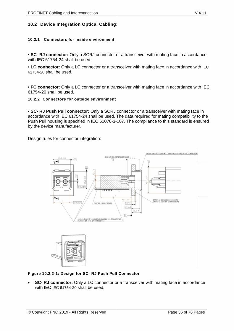
• SC- RJ Push Pull connector: Only a SCRJ connector or a transceiver with mating face in accordance with IEC 61754-24 shall be used. The data required for mating compatibility to the Push Pull housing is specified in IEC 61076-3-107. The compliance to this standard is ensured by the device manufacturer. Design rules for connector integration:
Figure 10.2.2-1: Design for SC- RJ Push Pull Connector
• SC- RJ connector: Only a LC connector or a transceiver with mating face in accordance with IEC IEC 61754-20 shall be used.
• LC Push Pull connector: Only a LC Push Pull connector or a transceiver with mating face in accordance with IEC 61076-3-123 shall be used. The compliance to this standard is ensured by the device manufacturer.
11 Cables for PROFINET Data Cabling
11.1 Balanced Cables PROFINET cables used are minimum based electrically on category 5 balanced LAN cables according to ISO/IEC 11801 Edition 2.0.Class D. In industrial applications networks with 2 pair and 4 pair cabling are required.
• The 2 pair cabling shall be realised as one star-quad or as 2 twisted pair design. • The 4 pair cabling shall be realised as two star-quad or as 4 twisted pair design.
In special applications (e.g. the use of trailing cables and frequently moved machine parts), cables are permitted whose design and mechanical parameters can deviate from the specifications of type A and type B cable (see Table 10.1.1, while retaining most of the electrical parameters (impedance levels etc.)). These cables are type C cables. Highly flexible copper cables generally have the finest stranded conductors and, for example, a highly resistant polyurethane outer sheath. Especially for use in robots Type R is created. Due to torsion stress in the application special design is necessary. Additionally we have defined requirements for a mechanical test. Various outer sheath materials are permitted in order to meet the various demands with regard to flame retardancy, resistance of industrial environments and exterior/underground laying (natural and synthetic oil, grease, coolants/lubricants, chemicals, high and low temperatures, UV radiation). The cable and used materials shall comply to national, European and international regulations. Industrial-type plug connectors type RJ45, protection type IP67, or a tried and tested industrial round plug connector M12, minimum category 5, are to be used as plug connectors. All balanced cables used shall comply with the parameters as described in 10.1-1.
Balanced 2 pair Cables (Type A, B ,R ,C) 11.1.1
2 pair Cable Type Application Type A Application Type B Application Type R Application Type C
Design 2 pair Data Cable 2 pair Data Cable 2 pair Data Cable 2 pair Data Cable Cable Installation Type
Stationary, no movement after installation
Flexible, occasional movement or vibration
Cable for robot applications
Special applications
System Concept: Cable Marking (at least)
“PROFINET Type A” “PROFINET Type B” “PROFINET Type R” “PROFINET Type C”
Outer Cable Diameter 5,5 - 8,0 mm 5,5 - 8,0 mm Application specific Wire Diameter 1,4 ±0,2 mm 1,4 ±0,2 mm Application specific Colour (Outer Sheath) Green RAL6018 Green RAL6018
(preferred) Green RAL6018 (preferred)
Wire identification (colours)
star quad 2 pair
white, yellow, blue, orange Pair 1: white (RXD+), blue (RXD-); Pair 2: yellow(TXD+), orange(TXT-)
Number of Wires 4 Cable Design 2 pairs or 1 star quad Shielding Design Type
Aluminium Foil + Copper Braiding Suitable for robot applications metal tape with 100 % coverage screen of copper wires: optical coverage minimum 85 % for braid and minimum 90% for spiralized (preferred braided screen)
≥ 80 dB at 30 MHz to 100 MHz; Segregation class d acc. EN 50174-2
Ambient Conditions: Tensile performance of the cable
50 N
Crush test of the cable
3000 N 3000 N Application Application
Pollution Degree Shock Vibration Operating Temperature Range
see Table 6-1 "Outside enclosure"
see Table 6-1 "Outside enclosure"
see Table 6-1 "Outside enclosure" and additional requirements for robot applications
see Table 6-1 "Outside enclosure"
* Restriction of the component approach is possible according to the specification of the cable manufacturer (reduction of the E2E link length shall be defined by the vendor in the cable specification).
Note: AWG dimensions are given for information only; normative dimensions of conductor sizes are given in metric size, i.e. in mm for the diameter of solid conductors and mm² for the cross section of stranded conductors.
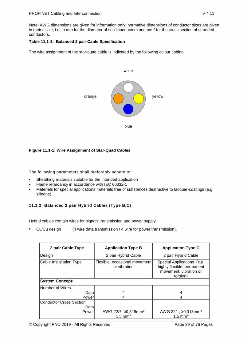
Table 11.1-1: Balanced 2 pair Cable Specification The wire assignment of the star-quad cable is indicated by the following colour coding:
white
yellow
blue
orange
Figure 11.1-1: Wire Assignment of Star-Quad Cables The following parameters shall preferably adhere to:
• Sheathing materials suitable for the intended application • Flame retardancy in accordance with IEC 60332-1 • Materials for special applications materials free of substances destructive to lacquer-coatings (e.g.
silicone)
Balanced 2 pair Hybrid Cables (Type B,C) 11.1.2
Hybrid cables contain wires for signals transmission and power supply.
• Cu/Cu design (4 wire data transmission / 4 wire for power transmission).
2 pair Cable Type Application Type B Application Type C
Design 2 pair Hybrid Cable 2 pair Hybrid Cable Cable Installation Type Flexible, occasional movement
or vibration Special Applications (e.g. highly flexible, permanent
(minimum Category 5) Delay Skew: <=20ns/100m Coupling attenuation ≥ 80 dB at 30 MHz to 100 MHz
Segregation class d acc. EN 50174-2 Ambient Conditions: Tensile performance of the cable
50 N Application specific
Crush test of the cable 3000 N 3000 N Application
Pollution Degree Shock Vibration Operating Temperature Range
See Table 6-1 "Outside enclosure"
Maximal Current in each Power-Wire:
For T<=55°C: 16A
For T>55°C the current is not specified but may be indicated in the relevant detailed specification of the cable manufacturer
(derating diagram)
Note: AWG dimensions are given for information only; normative dimensions of conductor sizes are given in metric size, i.e. in mm for the diameter of solid conductors and mm² for the cross section of stranded conductors.
Table 11.2-1: 2 pair Hybrid Cable Specification Note: The possible channel length of the hybrid cable depends on the power consumption of the connected devices.
4 pair Cable Type Application Type A Application Type B Application Type C
Design 4 pair Data Cable 4 pair Data Cable 4 pair Data Cable Cable Installation Type Stationary, no
movement after installation
Flexible, occasional movement or
vibration
Special Applications (e.g. highly flexible,
permanent movement, vibration
or torsion)
System Concept: Cable Marking (at least)
“PROFINET Type A 4 pair CATx”
“PROFINET Type B 4 pair CATx”
“PROFINET Type C 4 pair CATx”
Minimum Conductor Diameter or Cross Section
AWG 23/1 ≥0,546mm
AWG23/7 ≥0,254mm²
≤AWG 24/.. ≥0,485mm for solid
conductors ≥0,201mm² for
stranded conductors
Outer Cable Diameter 5,5 ...9,0 mm Application specific Wire Diameter 1,0 mm to 1,6 mm Application specific Colour (Outer Sheath) Green RAL6018 Application Wire Identification (colours)
4 pair
White/(Orange), Orange White/(Green), Green
White/(Blue), Blue White/(Brown), Brown
Ring or stripe marking on the white wire is optional
Delay Skew: <=20ns/100m between Pair Orange) and Pair Green Coupling attenuation ≥ 80 dB at 30 MHz to 100 MHz
segregation class d EN 50174-2 Ambient Conditions: Tensile performance of the cable
50 N
Crush test of the cable 2000 N 2000N Application
Pollution Degree Shock Vibration Operating Temperature Range
see Table 6-1 "Outside enclosure"
Note: AWG dimensions are given for information only; normative dimensions of conductor sizes are given in metric size, i.e. in mm for the diameter of solid conductors and mm² for the cross section of stranded conductors.
Table 11.3-1: Balanced 4 pair Cable Specification The following parameters shall preferably adhered to:
• Sheathing materials suitable for the intended application • Flame retardancy in accordance with IEC 60332-1 • Materials for special applications materials free of substances destructive to lacquer-coatings (e.g.
silicone)
11.1.3.1 Qualification test for PROFINET copper-cables
The Qualification Test shall be performed in accordance with the following standards: IEC 61156-1 Multicore and symmetrical pair/quad cables for digital communications - Part 1: Generic specification IEC 61156-5 Part 5: Symmetrical pair/quad cables with transmission characteristics up to 1 000MHz -horizontal floor wiring - Sectional specification IEC 61156-6 Part 6: Symmetrical pair/quad cables with transmission characteristics up to 1 000MHz- Work area wiring - Sectional specification ISO/IEC 11801 : Information technology - Generic cabling for customer premises IEC 60189-1 Low-frequency cables and wires with PVC insulation and PVC sheath. Part 1: General test and measuring methods IEC 60332–1-2 Tests on electric and optical fibre cables under fire conditions - Part 1-2: Test for vertical flame propagation for a single insulated wire or cable – Procedure for 1 kW pre-mixed flame
IEC 60811-100 Electric and optical fibre cables - Test methods for non-metallic materials - Part 100: General IEC 60811-203 Part 203: General tests - Measurement of overall dimensions IEC 60811-401 Part 401: Miscellaneous tests - Thermal ageing methods - Ageing in an air oven IEC 60811-501 Part 501: Mechanical tests - Tests for determining the mechanical properties of insulating and sheathing compounds IEC 60811-508 Part 508: Mechanical tests - Pressure test at high temperature for insulation and sheaths IEC 60811-509 Part 509: Mechanical tests - Test for resistance of insulations and sheaths to cracking (heat shock test) EN 50289-1-6 Communication cables - Specifications for test methods - Part 1-6: Electrical test methods - Electromagnetic performance EN 50289-3-16 Part 3-16: Mechanical test methods - Cable tensile performance EN 50396: Non electrical test methods for low voltage energy cables Test requirement for 2 pair PROFINET copper-cables are defined in the following table:
Type A and B Colour outer Jacket green Visual inspection
RAL 6018
All Colour Datawire White/(Orange) - Orange, White/(Green) - Green, White/(Blue) – Blue, White/(Brown)- Brown Ring or Stripe marking on the white wire is optional
Visual inspection
IEC 61784-5-x and this PROFINET Guideline
All Coupling attenuation ≥ 80 dB at 30 MHz to 100 MHz
EN50289-1-6
≥ 80 dB at 30 MHz to 100 MHz
All Operating temperature -20°C ...+70°C All cable material have to be designed for -20°C...+70°C
All Differential delay / Delay skew between Pair 1 (orange) and Pair 2 (green)
IEC 61156-5 <=20ns/100m
Type R Trailing chain test (horizontal)
bending radius: max. 15xD acceleration: ≥10 m/s² speed: min. 180 m/min chain length: ≥5 m cycles: ≥5 million
After 5 million cycles: Pass test of IEC 61156-6 (min. Category 5)
Type R Torsion test Torsion stress: ± 180/m Cycles: ≥5 million
After 5 million cycles: Pass test of IEC 61156-6 (min. Category 5)
Type R Reverse bending test Bending radius: max. 7xD Weight: 300 g
EN 50396 paragraph 6.4
After 1 million cycles: Pass test of IEC 61156-6 (min. Category 5)
Table 11.1.3-2: Test requirement 4 pair Balanced Cables
• Type B optical fibre cable for stationary or flexible use
• Type C optical fibre cable for special applications e.g. with permanent movement or vibration or torsion
All cable constructions (Type B and C) include two fibre elements. POF and PCF cables 11.2.2
11.2.2.1 Specification of POF and PCF cables Plastic optical fibre (POF) and Polymer clad fibre (PCF) cables shall comply with the requirements listed in Table 9.2.2.1-1. For more information see technical specification “Physical Layer Medium Dependent Sublayer on 650 nm Fibre Optics”, PI order no. 2.432.
Cable type Plastic optical fibre and polymer clad fibre cables
Design data cable data cable Cable installation type stationary, flexible,
depending on cable construction highly flexible, permanent movement
or vibration or torsion (special applications)
System concept:
Cable marking (at least)
PROFINET Type B + fibre type i.e.: PROFINET Type B 2P980/1000
PROFINET Type B 2K200/230
PROFINET Type C + fibre type i.e.: PROFINET Type C 2P980/1000
PCF: 0,37 +/-0,04 )*1 for type C cables refer to manufacturers data sheet
Table 11.2.2.1-1: Requirements for plastic and polymer clad optical fibre cables 11.2.2.2 Qualification test for POF and PCF cables The PROFINET qualification Test for Plastic optical fibre (POF) and Polymer clad fibre (PCF) cables shall be performed in accordance with Table 9.2.2.1-1 Cable type POF and PCF cables Characteristics Test Standard Requirements
Cable installation type
stationary, flexible, depending on cable construction
(type B cable)
highly flexible, permanent movement or vibration or torsion
(special applications) (type C cable)
Outer cable diameter (cables for use with PROFINET IP65/67 connectors) IEC 60811-1-1 max. 9,5 mm max. 9,5 mm Diameter secondary coating PCF IEC 60811-1-1 0,50 +/- 0,05 mm 0,50 +/- 0,05 mm Diameter subcable POF IEC 60811-1-1 2,2 +/- 0,1 mm 2,2 +/- 0,1 mm
Diameter subcable PCF IEC 60811-1-1 2,2 +/- 0,1 mm 2,2 +/- 0,1 mm
All-silica multimode optical fibre cables 11.2.311.2.3.1 Specification of all-silica multimode optical fibre cables All-silica multimode optical fibre cables shall comply with the requirements listed in Table 9.2.3.1-1.
Cable type All-silica multimode optical fibre cables
Design data cable data cable Cable installation type stationary, flexible,
depending on cable construction (type B cable)
highly flexible, permanent movement or vibration or torsion (special
applications) (type C cable)
System concept: Cable marking (at least)
PROFINET Type B + fibre type i.e.: PROFINET Type B 2G50/125 PROFINET Type B 2G62,5/125
PROFINET Type C + fibre type i.e.: PROFINET Type C 2G50/125
PROFINET Type C 2G62,5/125
Maximum length for PROFINET
2000 m 2000 m
Outer cable diameter (cables for use with IP20 connections)
No requirements No requirements
Outer cable diameter (cables for use with PROFINET IP65/67 connectors)
max. 9,5 mm
max. 9,5 mm
Diameter secondary coating 1,4 mm 1,4 mm Diameter subcable 2,9 mm 2,9 mm Colour (outer sheath) green RAL6018 depending on the application )*3 Colours (subcable) orange + black
orange with arrow (pointing direction of data stream)
orange + black orange with arrow
(pointing direction of data stream) Number of fibres 2 2 Ambient conditions: Minimum tensile strength 600 N depending on the application )*3 Bending radius (static long term)
> 15 times cable diameter )*2 depending on the application )*3
Pollution degree Shock Vibration Operating temperature range
see Table 6-1 "Outside enclosure" depending on the application )*3
Transmission performance requirements:
Relevant standard IEC 60793-2 Type according to IEC 60793-2
A1a , A1b
Core/cladding diameter 50/125 µm 62,5/125 µm
Nominal wavelength 1300 nm Bandwidth MHz referred to 1 km
>=500 MHz )*1
Maximum attenuation 1,5 dB/km )*1 )*1 measured in accordance with IEC 60793-1-40 and IEC 60793-1-41 )*2 Deviating bending radius are possible according to manufacturer's specifications. )*3 for type C cables refer to manufacturers data sheet
Table 11.2.3.1-1: Requirements for all-silica multimode optical fibre cables
11.2.3.2 Qualification test of all-silica multimode optical fibre cables The PROFINET qualification test of all-silica multimode optical fibre cables shall be performed in accordance with Table 10.2.3.2-1. Cable type All-silica multimode optical fibre cables
Characteristics Test Standard Requirements
Cable installation type
stationary, flexible, depending on cable
construction (type B cable)
highly flexible, permanent movement or vibration or
torsion (special applications)
(type C cable) Outer cable diameter (cables for use with PROFINET IP65/67 connectors)
IEC 60811-1-1 max. 9,5 mm
depending on the application
Diameter secondary coating
IEC 60811-1-1 1,4 +/- 0,1 mm 1,4 +/- 0,1 mm
Diameter subcable IEC 60811-1-1 2,9 +/- 0,1 mm 2,9 +/- 0,1 mm
Minimum tensile strength
IEC 60794-1-2, Methode E1
600 N; 100 m length; max. 1,0 dB Δ A (@ 1300 nm)
depending on the application
Bending radius
IEC 60794-1-2, Methode E11A
Bending radius 10 times cable diameter, 5 turns, 1 cycle, max. 0,1 dB (@ 1300 nm)
All-silica singlemode optical fibre cables 11.2.411.2.4.1 Specification of all-silica singlemode optical fibre cables All-silica singlemode optical fibre cables shall comply with the requirements listed in Table 10.2.4.1-1.
Cable type All-silica singlemode optical fibre cables
Design data cable data cable Cable installation type stationary, flexible
depending on cable construction (type B cable)
highly flexible, permanent movement or vibration or torsion
(special applications) (type C cable)
System concept: Cable marking (at least)
PROFINET Type B + fibre type i.e.: PROFINET Type B 2E9/125
PROFINET Type C + fibre type i.e.: PROFINET Type C 2E9/125
Outer cable diameter max. 9,5 mm depending on the application )*3 Diameter secondary coating 1,4 mm 1,4 mm Diameter subcable 2,9 mm 2,9 mm Colour (outer sheath) green RAL6018 depending on the application )*3 Colours (subcable) orange + black
orange with arrow (pointing direction of data stream)
orange + black orange with arrow
(pointing direction of data stream) Number of fibres 2 2 Ambient conditions: Minimum tensile strength (cable, long term)
600 N depending on the application )*3
Bending radius (Static long term) > 15 times cable diameter depending on the application )*3 Pollution degree Shock Vibration Operating temperature range
see Table 6-1 "Outside enclosure"
depending on the application )*3
Transmission performance requirements: Relevant standard IEC 60793-2 Type (according to IEC 60793-2) B1 Cladding diameter 125 µm ±2 µm Nominal wavelength 1300nm Maximum attenuation (at 1310 nm)
0,5 dB/km )*2
Cut-off wavelength < 1260 nm )*1 )*1 according IEC 60793-1-44
)*2 according IEC60793-1-40
)*3 for type C cables refer to manufacturers data sheet
Table 11.2.4.1-1: Requirements for all-silica singlemode optical fibre cables
11.2.4.2 Qualification test of all-silica singlemode optical fibre cables The PROFINET qualification test of all-silica singlemode optical fibre cables shall be performed in accordance with Table 10.2.4.1-1. Cable type All-silica singlemode optical fibre cables
Characteristics Test Standard Requirements
Cable installation type
stationary, flexible, depending on cable
construction (type B cable)
highly flexible, permanent movement or vibration or
torsion (special applications)
(type C cable) Outer cable diameter (cables for use with PROFINET IP65/67 connectors)
IEC 60811-1-1 max. 9,5 mm
depending on the application
Diameter secondary coating
IEC 60811-1-1 1,4 +/- 0,1 mm 1,4 +/- 0,1 mm
Diameter subcable IEC 60811-1-1 2,9 +/- 0,1 mm 2,9 +/- 0,1 mm
Minimum tensile strength
IEC 60794-1-2, Methode E1
600 N; 100 m length; max. 1,0 dB Δ A (@ 1300 nm)
depending on the application
Bending radius
IEC 60794-1-2, Methode E11A
Bending radius 10 times cable diameter, 5 turns, 1 cycle, max. 0,1 dB (@ 1300 nm)
PROFINET cord sets fulfil the PROFINET component specification and can be used concerning the PROFINET component model. The conformity of the PROFINET cord set to this specification shall be declared by the vendor.
PROFINET cabling is based on the End-to-End link. The End-to-End link extends the IEC 11801 channel about the plug connectors, which are mated to the PROFINET device (TE/PMD).The End-to-End link is specified in IEC 61918.
TE/ PMD
TE/ PMD
100 m channel
end-to-end link
Figure 12.1-1: End-to-End link
The conformity shall be declared for the PROFINET cord set. PROFINET cord set used shall comply with the following parameters:
Type PROFINET cord set Number of wires 4,8
Cable Type A,B Connector type PROFINET connector
for type A,B cable Cord set marking (additional to cable marking) “PROFINET cord set"
Cord Sets for Balanced Type A/B Cabling 12.1.1
Cords shall meet return loss (RL) and Next requirements specified in IEC 11801.
Insertion loss (IL) of cord sets shall not exceed the value stated for the given length: IL=IL cab* L / 100 + 2 * IL con IL cab= 22,0 dB / 100m @ 100 MHz, IL con = 0,4 dB (Informative values of IL cab at 100 MHz for PROFINET cord sets from IEC 11801)
Cord Sets for Balanced Type C Cabling 12.1.2Cords shall meet return loss (RL) and Next requirements specified in IEC 11801.
Insertion loss (IL) of cord sets shall not exceed the value stated for the given length:
IL=IL cab* L / 100 + 2 * IL con IL cab= 33,0 dB / 100m @ 100 MHz , IL con = 0,4 dB (Informative values of IL cab @ 100 MHz for PROFINET cord sets from IEC 11801)
12.2 Cabinet cord sets for balanced cabling
PROFINET Cabinet cord sets are cord sets for cabinet applications. PROFINET Cabinet cord sets fulfil the PROFINET component specification and can be used concerning the PROFINET component model. The conformity of the PROFINET cabinet cord set to this specification shall be declared by the vendor.
End-to-End link build up with PROFINET cabinet cord sets meet the requirement described in the following Figure 12.2-1:
Connecting hardware performance is influenced by the properties of the plug termination and, therefore cords should be tested to determine the quality of the assembly. This clause specifies the minimum requirements for cords. The test methods and mechanical stresses are specified in IEC 61935-2. All requirements of this clause have to be met after first exposing the device under test to mechanical stress. Cords shall meet the electrical and mechanical requirements of IEC 61935-2. The cabinet cord sets shall meet a tightened flexures test in accordance to IEC 61935-2 7.3. The cabinet cord shall fulfil after the specified flexures at least the category 5 patch cord test according to ISO/IEC 11801 Edition 2.0. PROFINET cabinet cord sets shall be labelled as PROFINET cabinet cord sets. Cable used to build up a cabinet cord are based electrically on at least category 5 balanced LAN cables according to ISO/IEC 11801 Edition 2.0.Class D. Connectors used to build up a cabinet cord shall be based on the mating face as defined in clause 9.1. or 9.2..
Qualification test for PROFINET cabinet cord sets 12.2.1
The conformity shall be declared for the PROFINET cabinet cord set.
PROFINET Cabinet cord set used shall comply with the following parameters:
*1Cable Coupling Attenuation 80dB (Measurement of the coupling attenuation according to EN 50289-1-6)
*2 Connector Coupling 45 dB (Measurement of the coupling attenuation according to IEC 62153-4-12)
: PROFINET Cabinet cord set specification 12.2.2
The following parameters shall preferably adhered to:
• Sheathing materials suitable for the intended application
• Materials for special applications materials free of substances destructive to lacquer-coatings (e.g. silicone)
Additional test parameters are described in the Draft IEC 61784-5-3 and in Table 8-1: Plug Connector Specifications for Inside Applications (Data Cabling).
The cable used to build up a cabinet cord shall comply with the following standards:
Flame retardancy IEC 60332–1-2 Has to pass the test
Sheath pressure test at high temperature
IEC 60811-508 Max. 50 %
Heat shock test IEC 60811-509 No cracks
Tensile performance of the cable
50N
EN 50289-3-16 IEC 61156-6
Colour outer Jacket green Visual inspection
RAL 6018
Coupling attenuation ≥ 80 dB at 30 MHz to 100 MHz
EN50289-1-6
≥ 80 dB at 30 MHz to 100 MHz
Operating temperature -20°C ...+70°C All cable material have to designed for -20°C...+70°C
Differential delay / Delay skew between Pair 1 (orange) and Pair 2 (green)
IEC 61156-6 <=20ns/100m
The connectors used to build up a cabinet cord shall be in accordance to the specification of the inside connector in chapter 11.1.
The Qualification Test for the cabinet cord sets shall meet return loss (RL) and Next requirements specified in IEC 11801 for balanced cords (at least category 5).
The connectors used to build up a cabinet cord shall be in accordance to the specification of the inside connector in chapter 11.1. The Qualification Test for the cabinet cord sets shall meet return loss (RL) and Next requirements specified in IEC 11801 for balanced cords (at least category 5).
PROFINET Cabinet cord sets are cord sets for cabinet applications. PROFINET Cabinet cord sets fulfil the PROFINET component specification and can be used concerning the PROFINET component model. The conformity of the PROFINET cabinet cord set to this specification shall be declared by the vendor. Connecting hardware performance is influenced by the properties of the plug termination and, therefore cords should be tested to determine the quality of the assembly. PROFINET cabinet cord sets shall be labelled as PROFINET cabinet cord sets. Connectors used to build up a cabinet cord shall be based on the mating face as defined in clause 10.1, 10.2. or 10.3. 12.3.1.1 Qualification test for PROFINET cabinet cord sets for optical cabling The conformity shall be declared for the PROFINET cabinet cord set.
PROFINET FO Cabinet cord set used shall comply with the following parameters:
PROFINET FO cabinet cord set
Comment only harnessed cord sets are defined Application Inside enclosure Cable colour (outer sheath) RAL 6018 Cabinet cord set marking 2 pair PROFINET FO Cabinet Cord Set PROFINET Component X Cable diameter, nominal 2.8 mm ( +/- 0.1) Diameter seondary coating 0,9 / 1,4 mm Cable type Duplex-Cable
Connector
SCRJ (IEC 61754-24-11) SC-Duplex (IEC 60874-14-x)
LC (IEC 61754-20) Cable performance SM OS 2 Cable performance MM OM 2 Insertion Loss SM, max. 0.4 dB Insertion Loss MM, max. 0.7 dB Temperature ( Trasport & storage) - 25 bis +70 °C Temperature (Installation) -10°C... 70°C Temperature (in operation) - 20 bis +70 °C Crush 500N / 1 Minute Impact 20 (Wp=0,74J, r=25mm) Tensile performance 200 N / 5 Minutes, Bending Radius r=30 mm (6 Windungen, 3 Zyklen) Repeated bending 5000 Zyklen bei r=60 mm
Torsion 10 (±360°, Länge = 1000 mm,
F =20 N) Kink 5 × the cable diameter Sheath pull-off force for optical fibre cable for use in patch cords fulfilled Sheath shrinkage for optical fibre cable for use in patchcords fulfilled
Buffered fibre movement under compression in optical fibre cables for use in patchcords fulfilled Test for vertical flame spread Test for vertical flame propagation fulfilled Measurement of smoke density of cables burning fulfilled max. length 20m The cable used to build up a cabinet cord shall comply with the following standards:
Table 12.3-1: PROFINET Cabinet cord set specification
The following parameters shall preferably adhered to: • Sheathing materials suitable for the intended application • Flame retardance in accordance with IEC 60332-1 • Materials for special applications materials free of substances destructive to lacquer-coatings (e.g. silicone) Additional test parameters are described in the Draft IEC 61784-5-3 and in Table 8-1: Plug Connector Specifications for Inside Applications (Data Cabling). The cable used to build up a cabinet cord shall comply with the following standards:
Buffered fibre movement under compression IEC 60794-2-50 Method E22 Test for vertical flame spread Test for vertical flame propagation
IEC 60332-3-24 Cat. C IEC 60332-1-2 Annex A
Measurement of smoke density of cables burning IEC 61034-2
The connectors used to build up a cabinet cord shall be in accordance to the specification of the inside connector in chapter 11.1.
12.4 End-to-End Link assemblies for balanced cabling PROFINET End-to-End Link assemblies are assemblies to connect active PROFINET devices. PROFINET End-to-End Link assemblies fulfil the PROFINET End-to-End link specification.
Figure12.4-1 shows an End-to-End link without interconnections of 100 m length with connectors installed directly at both ends of the cable.
TE/ PMD
TE/ PMD
100 m channel
end-to-end link
Figure 12.4-1– End-to-End link without interconnections
Figure 12.4-1 shows an assembled End-to-End link of 100 m length, containing an intermediate plug connection established with a bulkhead.
TE/ PMD
TE/ PMD bulk -
head
100 m channel
end-to-end link
Figure 12.4-2– Assembled End-to-End link
1. Max. NEXT requirements Class D according ISO/IEC TR 11801-9902
Formula 0-1– Formula for NEXT limits for an End-to-End link
Procedures for measurement of the End-to-End link 12.4.1
The traditional definition of the channels excludes the contribution of the end connections (connections to the application or the field tester) to the overall NEXT. In order to allow for two alternative but functional equivalent test method values for the End-to-End Link need to be defined in order to support the different test scenario.
TE/ PMD
TE/ PMD
100 m channel
end-to-end link
Table 12.4.1-1 – Definition of the reference plain
The procedures of the End-to-End measurement are specified in ISO/IEC 14763-4.
12.5 Bulkheads for Balanced Cabling Bulkheads are placed between different environmental conditions, different connector mating faces or different installation requirements.
PROFINET bulkheads are implemented in different versions:
1. Adapter
a. Adapter IP 67 for the Push Pull connector, M12 connector, Hybrid connector on both side of the adapter
b. Adapter IP 20 for RJ 45 connector on both side of the adapter
2. Cable Adapter for the Push Pull connector, M12 connector, Hybrid connector or RJ 45 connector directly terminated to the PROFINET cable
3. Panel feed-through for the Push Pull connector, M12 connector or Hybrid connector on one side and the RJ 45 connector on the other side
Table 12.5.-1 – Definition of the different Bulkhead connections
The PROFINET bulkhead 12.5.1The PROFINET bulkhead is counted as 1 connector pair within the PROFINET component model. In an End-to-End link a maximum of 4 PROFINET bulkheads is allowed.
The characteristics of this bulkhead correspond to the connector characteristics in Clause 10.2.4 of IEC 11801 “Connecting hardware for balanced cabling”.
12.5.1.1 Qualification test for Bulkheads The Qualification Test of Bulkheads shall be performed in accordance with the following standards: ISO/IEC 11801-series: Generic cabling
13 24 Volt Cabling
The PROFINET 24 Volt Cabling is intended to be used either with an integrated functional earth (FE) or without a functional earth. There are dedicated connectors and cable designs.
PROFINET recommends the termination to the functional earth (FE) by an external termination point on the device. In this case the 4 way power cabling without functional earth (FE) should be used.
All PROFINET devices shall be equipped with an external functional earth (FE) termination point.
For further information see guideline Order Number 8.101 (Recommendations for functional grounding and bonding).
The PROFINET 24 Volt power supply of PROFINET devices is divided in two different power classes:
1. The supply is in star topology (current is limited to the demand of one device)
2. The supply is in line topology (higher current)
Power Class: 1 2Application:
24 Volt Power Supply in star topology
24 Volt Power Supply in line or star topology
Operating current: max. 4 A max. 16 A (including power class 1)
Operating voltage 24 Volt 24 VoltNumber of circuits: 1 (optional 2) 1 (optional 2)Functional earth (FE): optional optional Table 13-1: Power Classes for the 24 Volt installation
13.1 Connectors for 24 Volt Cabling
The connectors described in this guideline are the approved PROFINET connectors for the 24 Volt Power Supply of all PROFINET devices in “Outside” Applications.
The connectors shall comply to one of the Power Classes of Table 13-1: Power Classes for the 24 Volt installation.
The connectors shall comply to Table 13-2: Connector solutions for the 24 Volt installations. Only for special applications other connectors can be used without influencing the certification of the devices.
Protection level (Tabelle 5-1 Outside Environment): IP 65/67 Number of contacts: 5 Rated current @ 40°C (IEC 60 512): 16 A Wire gauge min: 0,75 mm² Wire gauge max: 2,5 mm² Rated voltage (Pollution grade 2 3): 24 Volt mating cycles: 100 Cable gauge max.: 12,5 mm Functional earth: Pin 5 PROFINET Contact Arrangement L1: Pin 1 PROFINET Contact Arrangement L2: Pin 3 PROFINET Contact Arrangement N1: Pin 2 PROFINET Contact Arrangement N2: Pin 4
Protection Class see Table 6-1 "Outside
enclosure" Pollution Degree Shock Vibration Operating Temperature Range
Table 13-2: Connector solutions for 24 Volt installations
The characteristics of the installed cable are also to be considered in the selection of the connector (e.g. derating).
Colour Coding for 24 Volt connectors 13.1.1
All PROFINET connectors for field termination shall be equipped with an additional colour coding in the termination area according to Table 13 1-1: Colour Coding for 24 Volt connectors. The colour coding is matched to the PROFINET 24 power cables specified in Section 13.2: Cables for 24 Volt Cabling.
L1 Pin 1 Brown Pin 1 Brown N1 Pin 2 Blue Pin 3 Blue L2 Pin 3 Black Pin 4 Black N2 Pin 4 White Pin 2 White
FE Pin FE no colour Pin FE no colour
Table 13-1-1: Colour Coding for 24 Volt connectors
24 Volt Push Pull connector 13.1.2
Push pull connectors (IP65/67 or higher) can be used for 24 Volt Power supply up to 16 Amp and two circuits. A 5-pin plug connector shall be applicable for all wires. Devices shall be fitted with the appropriate sockets. For line topologies is a junction possible inside the device or with an external T- junction. The design of the plug- and socket-connector is complete contact-protected. This enables the use of the same plug connectors at both ends because no pin-socket change is necessary.
Figure 13.1.1-1: Picture of the Push Pull Plug 24 Volt Connector
T-connector
Push Pull T-Connectors are designed to realise a lined Topology outside of the device to archive hot swapping of devices. T-connectors shall have the capability for the specified connector and cabling solution. The rated current is the sum of all ports.
13.1.2.1 Qualification Test for 24 Volt Push Pull connector The Qualification Test shall be performed in accordance with the following standards: IEC-PAS 61076-3-1xx - Push-Pull-Power Additional test parameters are described in Installation Guideline Table Table 13 2: Connector solutions for the 24 Volt installation.
Figure 13.1.2-1: Picture of M12 L-Coded 24 Volt Connector
The M12 L-coded connectors described below are suitable for the supply of 24 Volt Power to a device.
Devices for line topology shall be equipped with a female connector and a male connector. The voltage carrying mating face (power source) of a device shall be female. System cable in general are harnessed with a female and a male connector.
Figure 13.1.2-2: M12 L-coding contact position 5 way (4 + FE) front view
Figure 13.1.2-3: M12 L-coding cable termination for power source devices
The following two styles of the M 12 L-coded connectors shall be used for PROFINET 24 Volt Power:
Figure 13.1.2-7: M12 L-coding orientation of coding; position of coding to cable outlet direction
T-connector
M12-L coded T-Connectors are designed to realise a line topology outside of the device. T-connectors shall have the same capabilities for the specified connector and cabling solution as defined by this specification. 13.1.3.1 Qualification Test for M12 Connector L-coded
The Qualification Test shall be performed in accordance with the following standards: 61076-2-111 section 4.3.4. “L-coding” Additional test parameters are described in Installation Guideline Table Table 13-2: Connector solutions for the 24 Volt installation
13.2 Cables for 24 Volt Cabling
Various outer sheath materials are permitted in order to meet the various demands with regard to flame retardancy, resistance of industrial environments and exterior/underground laying (natural and synthetic oil, grease, coolants/lubricants, chemicals, high and low temperatures, UV radiation).
The cable and used materials shall comply to national, European and international regulations.
PROFINET 24V Power Cable 2,5 mm² Profinet 24V DC Power
Cable Types Cable Installation Type Fixed and flexible installation, occasional movement or vibration,
Corresponding to Application Type A and B (table 11.1-1) Design 4 x 0,75 mm² or
5 x 0,75 mm² 4 x 1,5 mm² or
5 x 1,5 mm² 4 x 2,5 mm² or
5 x 2,5 mm² Which Plug for which Cable
Type Push Pull Power, M12 L-coded 1), 2)
Number of Wires 4 or 5
Rated Voltage 300 V Current-carrying capacity
per conductor at 40°C ambient temperature 3)
8 A 16 A
nominal conductor cross section
0,75 mm² 1,5 mm² 2,5 mm²
Wire Construction flexible conductor Wire Identification 5 wires with colours:
Brown (L1), Blue (N1), Black (L2), White (N2), Optional: 1 wire Pink (Functional Earth) 4)
Colour (Outer Sheath) Black (without Functional Earth) or Grey (with Functional Earth) Cable Marking (at least) “PROFINET 24V Power
4x0,75” (without Functional Earth) or “PROFINET 24V Power 4x0,75 + FE “ (with Functional Earth)
“PROFINET 24V Power 4x1,5” (without Functional Earth) or “PROFINET 24V Power 4x1,5 + FE “ (with Functional Earth)
“PROFINET 24V Power 4x2,5” (without Functional Earth) or “PROFINET 24V Power 4x2,5 + FE “ (with Functional Earth)
Operating Temperature Range
see Table 6-1 "Outside enclosure"
1) M12 L-coded pinning compatibility applies only to the pins themselves. For full plug-in compatibility, the shape of the casing of industrial connectors shall also be taken into account. The specified M12 L-coded receptacle (Jack) for “Outside” applications has to be mating compatible with the M12 L-coded Plug, 16A, derating in accordance with IEC 61984. 2) also applicable for 7/8” and M12 a-coded connectors 3) Derating in accordance with IEC 60204-1 und IEC 60364-5-52 4) The functional earth should in future comply with DIN EN 60445 VDE 0197 (2018-02) with a pink core (standard cables for PROFINET get a pink FE core). The connectors will be marked with a FE imprint in the future. Existing 24 Volt cables (grey functional earth), according to guideline 4.0, are still PROFINET compliant.
Table 13.2-1: 24V Power Supply Cable Specification
13.2.1.1 Qualification test for PROFINET 24 Volt cables
Test requirement for PROFINET 24 Volt cables are defined in the following table:
Cable Type to be tested
Test-Title
Severity or condition of
test
Measurement to be
performed
Requirements
all Conductor class Min. class 5 IEC 60228 class 5 or class 6 of IEC 60228
13.3 Cord sets for 24 Volt Cabling PROFINET cord sets for 24 Volt cabling is a combination of a PROFINET connector and a PROFINET 24 Volt cable
Table 13.3-1: PROFINET 24 Volt Power cord sets
The conformity of the PROFINET cord set to this specification shall be declared by the vendor.
13.3.1.1 Qualification test for PROFINET 24 Volt cord sets The Qualification Test shall be performed in accordance to the cable and connector specification.
14 Connector for PROFINET Signal Cabling
14.1 Push Pull Signal connector
For Signal applications the standardised shielded 10 pole Push Pull Variant 14 free and fixed connector should be used. If the Push Pull interface is used for Data applications in the same device, the standardised shielded 10 pole Push Pull Variant 14 free and fixed connector shall be used for Signal applications. The shielded 10 pole Push Pull Variant 14 free and fixed connector is described in the standard: IEC/PAS 61076-3-119: Connectors for electronic equipment - Product requirements - Part 3-119: Rectangular connectors - Detail specification for unshielded, free and fixed 10 way connectors with push-pull coupling for industrial environments with frequencies up to 100 MHz.
Figure 14.1-1: Example of a Push Pull Signal Connector
The Signal Connector is to be used where decentralized field devices are to be connected via one combined connection with user specific pin assignment.
The single contacts of the connector shall be used in accordance to the table below:
Push Pull Signal connector: Rated Current: max. 3 A per contact
Rated voltage 24 Volt Number of contacts 10 locking mechanism Push Pull Conductor cross-section: 0,08 - 0,75 mm² Outer cable diameter: 5 -10 mm
Figure 14.1-2: Basic parameters for shielded 10 pole Push Pull free and fixed connector.
Qualification Test for PROFINET Signal Cabling 14.1.1The qualification test shall be performed for outside enclosures in accordance with the following standard: IEC PAS 61076-3-119
15 Application specific Cabling and Interconnection Technology
15.1 Connector Definition according to AIDA Standard The following connectors fulfil the requirements of German car manufacturers (AIDA: Automation Initiative of German Domestic Automobile Manufacturers):
The qualification test shall be performed in accordance with the appropriate standard for the connector. For the ISO 23570 power bus conector the Qualification Test shall be performed in accordance with the following standard: ISO 23570-3
Design specification for power bus connectors of the ISO 23570-3.