24
ADVANCED REMOTE CONTROL SYSTEMS PROFLAME 2 Basic, Standard, Complete 9.955.116 02 Subject to change without notice w w w . s i t g r o u p . i t
ADVANCED REMOTE CONTROL SYSTEMS
PROFLAME 2 Basic, Standard, Complete
9.95
5.11
6 0
2
S
ubje
ct to
cha
nge
with
out n
otic
e
w w w . s i t g r o u p . i t
2
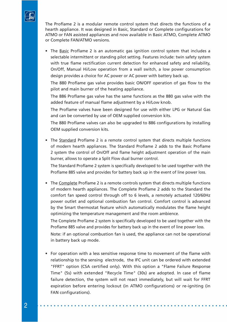
The Proflame 2 is a modular remote control system that directs the functions of a hearth appliance. It was designed in Basic, Standard or Complete configurations for ATMO or FAN assisted appliances and now available in Basic ATMO, Complete ATMO or Complete FAN/ATMO versions.
• The Basic Proflame 2 is an automatic gas ignition control system that includes a selectable intermittent or standing pilot setting. Features include: twin safety system with true flame rectification current detection for enhanced safety and reliability, On/Off, Manual Hi/Low operation from a wall switch, a low power consumption
design provides a choice for AC power or AC power with battery back up.
The 880 Proflame gas valve provides basic ON/OFF operation of gas flow to the pilot and main burner of the heating appliance.
The 886 Proflame gas valve has the same functions as the 880 gas valve with the added feature of manual flame adjustment by a Hi/Low knob.
The Proflame valves have been designed for use with either LPG or Natural Gas and can be converted by use of OEM supplied conversion kits.
The 880 Proflame valves can also be upgraded to 886 configurations by installing
OEM supplied conversion kits.
• The Standard Proflame 2 is a remote control system that directs multiple functions of modern hearth appliances. The Standard Proflame 2 adds to the Basic Proflame 2 system the control of On/Off and flame height adjustment operation of the main burner, allows to operate a Split Flow dual burner control.
The Standard Proflame 2 system is specifically developed to be used together with the
Proflame 885 valve and provides for battery back up in the event of line power loss.
• The Complete Proflame 2 is a remote controls system that directs multiple functions of modern hearth appliances. The Complete Proflame 2 adds to the Standard the comfort fan speed control through off to 6 levels, a remotely actuated 120/60Hz power outlet and optional combustion fan control. Comfort control is advanced by the Smart thermostat feature which automatically modulates the flame height optimizing the temperature management and the room ambience.
The Complete Proflame 2 system is specifically developed to be used together with the Proflame 885 valve and provides for battery back up in the event of line power loss.
Note: if an optional combustion fan is used, the appliance can not be operational in battery back up mode.
• For operation with a less sensitive response time to movement of the flame with
relationship to the sensing electrode, the IFC unit can be ordered with extended
"FFRT" option (CSA certified only). With this option a "Flame Failure Response
Time" (5s) with extended "Recycle Time" (30s) are adopted. In case of flame
failure detection, the system will not react immediately, but will wait for FFRT
expiration before entering lockout (in ATMO configurations) or re-igniting (in
FAN configurations).
3
mitt
e
PROFLA
MF
885 PROFLAME Combination Gas Control SPLIT FLOW
OFLAME
MC
880 PROFLAME Combination Gas Control
IFC
885 PROFLAME Combination Gas Control
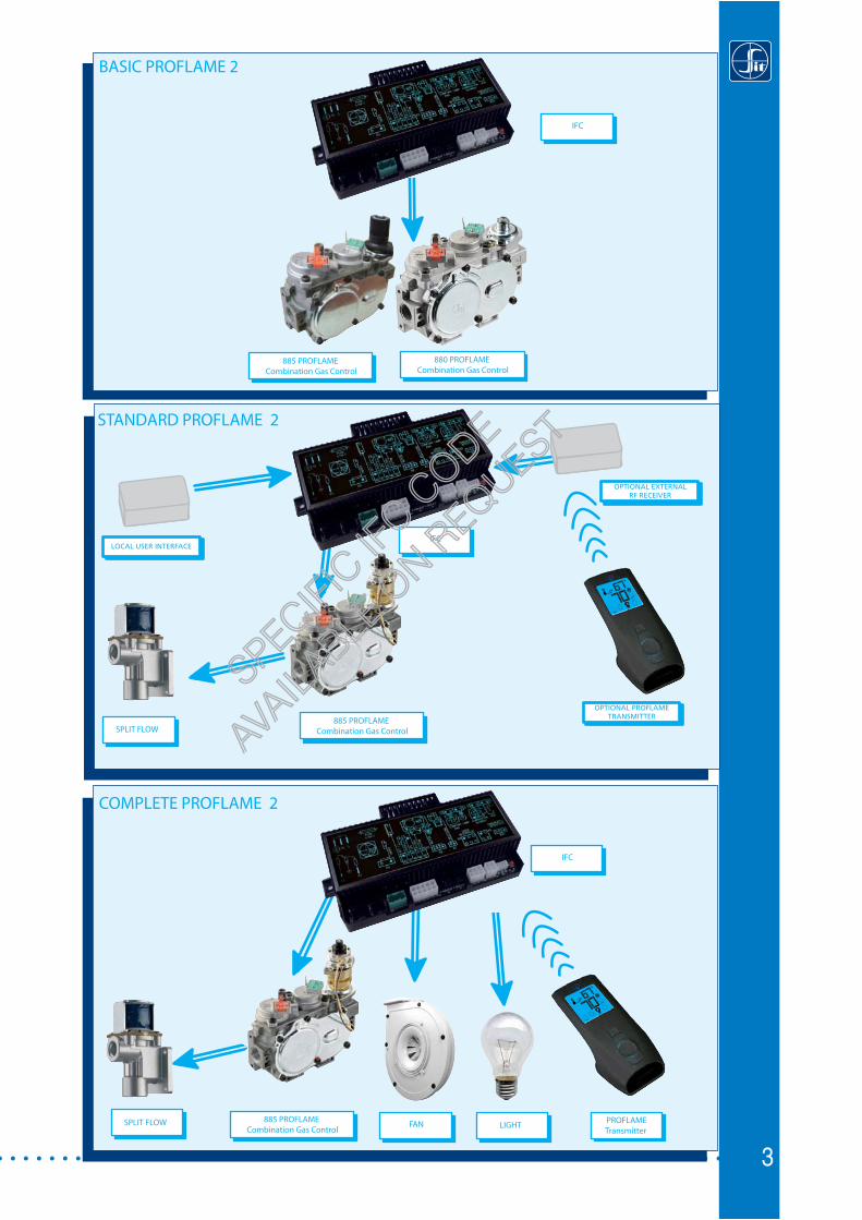
BASIC PROFLAME 2
STANDARD PROFLAME 2
er
PROFLAMETransmitter
IFC
ME
FLAM
885 PROFLAME Combination Gas Control
SPLIT FLOW
COMPLETE PROFLAME 2
FAN LIGHT
LOCAL USER INTERFACE
PRO
FLAM
F IFC
PROFLAM
F
OPTIONAL EXTERNALRF RECEIVER
OPTIONAL PROFLAME TRANSMITTER
SPECIFIC
IFCCODE
AVAILA
BLEON
REQUEST

4
MAIN CHARACTERISTICS
Feature Transmitter PROFLAME 2Icon
TMFSLA(1) TMFSL(2) TMFL(3)
Room Temperature Display • • •Child Lock • • •Low Battery indicator • • •On/Off Thermostat • • •Flame On/Off & Modulation (6 Levels) • • •Smart Thermostat • • •Fan Speed Control (6 Levels) • • •On/Off Auxiliary Outlet (120V) ••Split flow (dual flame) •• • IPI/CPI (4) •• • •Light modulation (6 levels) •• • •
Referring to the remote control:
(1) TMFSLA indicates enabled function: Thermostat, Modulator flame, Fan, Split flow, Lights modulation, Auxiliary output
(2) TMFSL indicates enabled function: Thermostat, Modulator flame, Fan, Split flow, Lights modulation
(3) TMFL indicates enabled function: Thermostat, Modulator flame, Fan, Lights modulation
(4) CPI indicates Continous Pilot Ignition; IPI indicates Intermittent Pilot Ignition
(•) Indicates included Features
The table below shows the configurations currently available.
5
The BASIC System consists of four main elements:1. Profl ame 2 Integrated Fireplace Control (IFC) Basic model2. Profl ame 880, or 886 families of gas valves 3. Pilot assembly4. Wiring harness to connect the IFC to the gas valve, pilot burner and control switches.
The STANDARD System consists of seven main elements:1. Profl ame 2 Integrated Fireplace Control (IFC) Standard model 2. Profl ame Gas Valve 885 family (also the 880, 886 families are compatible)3. Wiring harness to connect the IFC to the gas valve stepper motor, control switches and to
the Split Flow Control4. Profl ame 2 Transmitter and receiver (optionals)5. Pilot assembly6. Split Flow valve (optional)7. Local user interface.
The COMPLETE System consists of seven elements (ATMO confi guration), eight elements (FAN confi guration):
1. Profl ame 2 Integrated Fireplace Control (IFC) Complete model2. Profl ame Gas Valve 885 family (also the 880, 886 families are compatible)3. Wiring harness to connect the IFC to the control switches, and -depending on the FAN/
ATMO confi guration- to the APS4. Profl ame 2 Transmitter5. Pilot assembly6. Split Flow valve (optional)7. Comfort fan, dimmable lights, auxiliary device (optional)8. In Fan confi guration, the combustion Fan with Air Pressure Switch (APS) safety device.
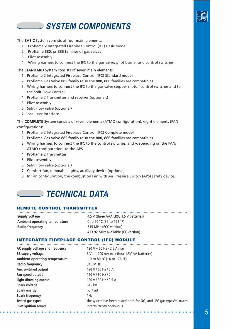
TECHNICAL DATA
REMOTE CONTROL TRANSMITTER
Supply voltage 4.5 V (three AAA LR03 1.5 V batteries)Ambient operating temperature 0 to 50 °C (32 to 122 °F)Radio frequency 315 MHz (FCC version) 433.92 MHz available (CE version)
AC supply voltage and frequency 120 V ~ 60 Hz - 2.5 A max BB supply voltage 6 Vdc - 200 mA max (four 1.5V AA batteries)Ambient operating temperature -10 to 80 °C (14 to 176 °F)Radio frequency 315 MHzAux switched output 120 V / 60 Hz / 5 AFan speed output 120 V / 60 Hz / 2Light dimming output 120 V / 60 Hz / 0.5 A Spark voltage >15 kVSpark energy >0,7 mJSpark frequency 1HzTested gas types the system has been tested both for NG, and LPG gas types/mixturesPilot ignition source Intermittent/Continuous
INTEGRATED FIREPLACE CONTROL (IFC) MODULE
SYSTEM COMPONENTS
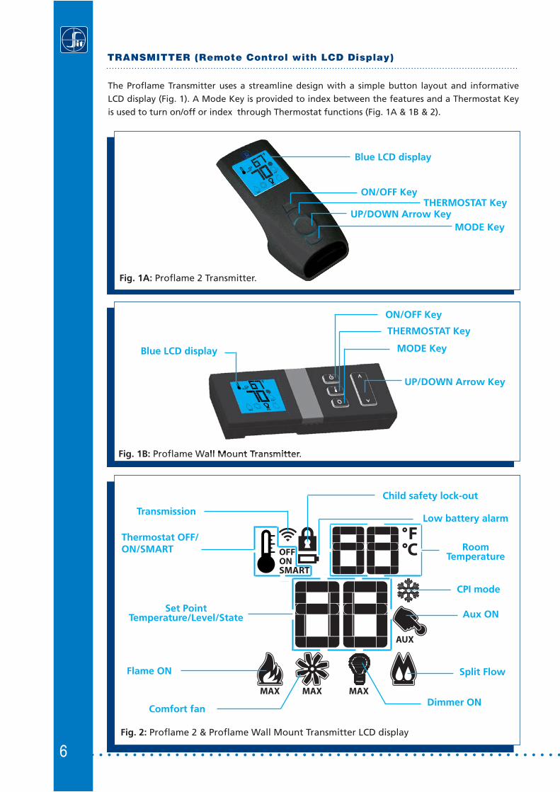
6Fig. 2: Proflame 2 & Proflame Wall Mount Transmitter LCD display
Low battery alarm
Child safety lock-out
RoomTemperature
Dimmer ON
Set PointTemperature/Level/State
Flame ON
Thermostat OFF/ON/SMART
Comfort fan
Transmission
Split Flow
Aux ON
CPI mode
TRANSMITTER (Remote Control with LCD Display)
The Proflame Transmitter uses a streamline design with a simple button layout and informative LCD display (Fig. 1). A Mode Key is provided to index between the features and a Thermostat Key is used to turn on/off or index through Thermostat functions (Fig. 1A & 1B & 2).
Fig. 1A: Proflame 2 Transmitter.
Blue LCD display
UP/DOWN Arrow Key
ON/OFF KeyTHERMOSTAT Key
MODE Key
Fig. 1B: Proflame Wall Mount Transmitter.
Blue LCD display
UP/DOWN Arrow Key
ON/OFF Key
THERMOSTAT Key
MODE Key
7
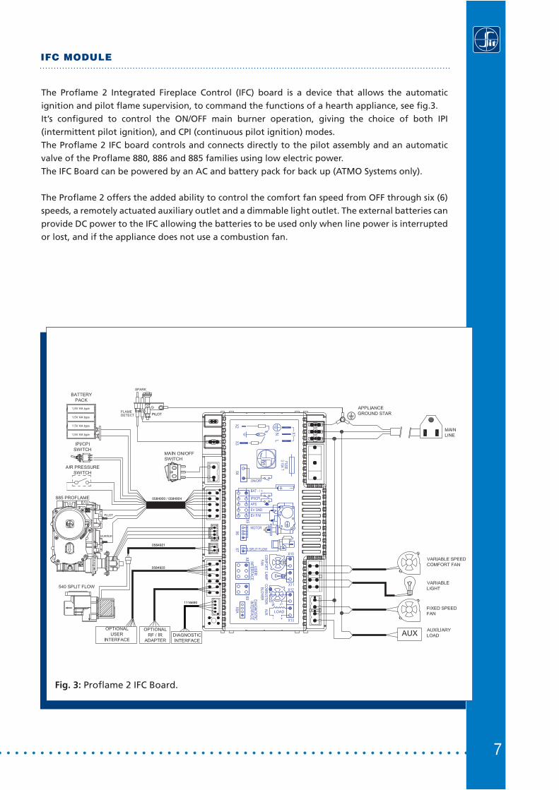
IFC MODULE
Fig. 3: Proflame 2 IFC Board.
The Profl ame 2 Integrated Fireplace Control (IFC) board is a device that allows the automatic ignition and pilot fl ame supervision, to command the functions of a hearth appliance, see fi g.3.It’s confi gured to control the ON/OFF main burner operation, giving the choice of both IPI (intermittent pilot ignition), and CPI (continuous pilot ignition) modes.The Profl ame 2 IFC board controls and connects directly to the pilot assembly and an automatic valve of the Profl ame 880, 886 and 885 families using low electric power.The IFC Board can be powered by an AC and battery pack for back up (ATMO Systems only).
The Profl ame 2 offers the added ability to control the comfort fan speed from OFF through six (6) speeds, a remotely actuated auxiliary outlet and a dimmable light outlet. The external batteries can provide DC power to the IFC allowing the batteries to be used only when line power is interrupted or lost, and if the appliance does not use a combustion fan.
PILOT
1116690
0584922
0584921
0584920 / 0584924
8
INSTALLATION
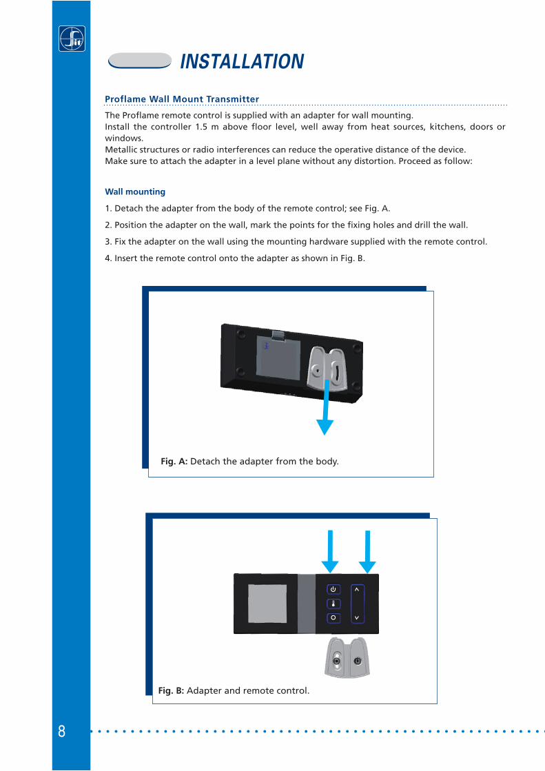
Proflame Wall Mount Transmitter
The Proflame remote control is supplied with an adapter for wall mounting. Install the controller 1.5 m above floor level, well away from heat sources, kitchens, doors or windows.Metallic structures or radio interferences can reduce the operative distance of the device.Make sure to attach the adapter in a level plane without any distortion. Proceed as follow:
Wall mounting
1. Detach the adapter from the body of the remote control; see Fig. A.
2. Position the adapter on the wall, mark the points for the fixing holes and drill the wall.
3. Fix the adapter on the wall using the mounting hardware supplied with the remote control.
4. Insert the remote control onto the adapter as shown in Fig. B.
Fig. B: Adapter and remote control.
Fig. A: Detach the adapter from the body.
9
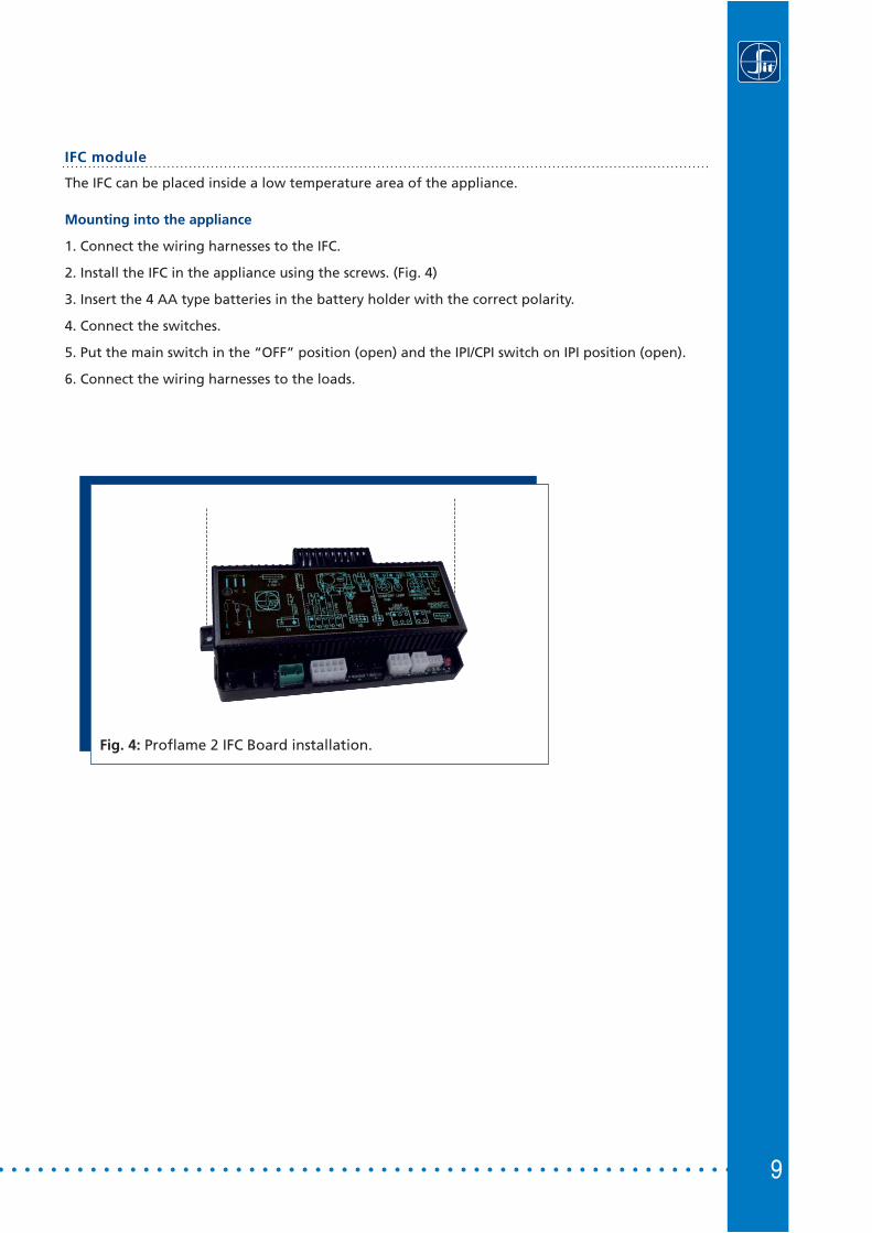
IFC module
The IFC can be placed inside a low temperature area of the appliance.
Mounting into the appliance
1. Connect the wiring harnesses to the IFC.
2. Install the IFC in the appliance using the screws. (Fig. 4)
3. Insert the 4 AA type batteries in the battery holder with the correct polarity.
4. Connect the switches.
5. Put the main switch in the “OFF” position (open) and the IPI/CPI switch on IPI position (open).
6. Connect the wiring harnesses to the loads.
Fig. 4: Proflame 2 IFC Board installation.
10
INSTALLATION
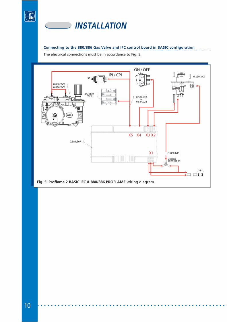
Connecting to the 880/886 Gas Valve and IFC control board in BASIC configuration
The electrical connections must be in accordance to Fig. 5.
0.880.XXX0.886.XXX
0.190.XXX
0.584.920
0.584.307
0.584.952
Fig. 5: Proflame 2 BASIC IFC & 880/886 PROFLAME wiring diagram.
GROUND
Chassisconnection
0.584.920or
0.584.924
X5 X4 X3 X2
X1
ON / OFFIPI / CPI
BATTERYPACK
11
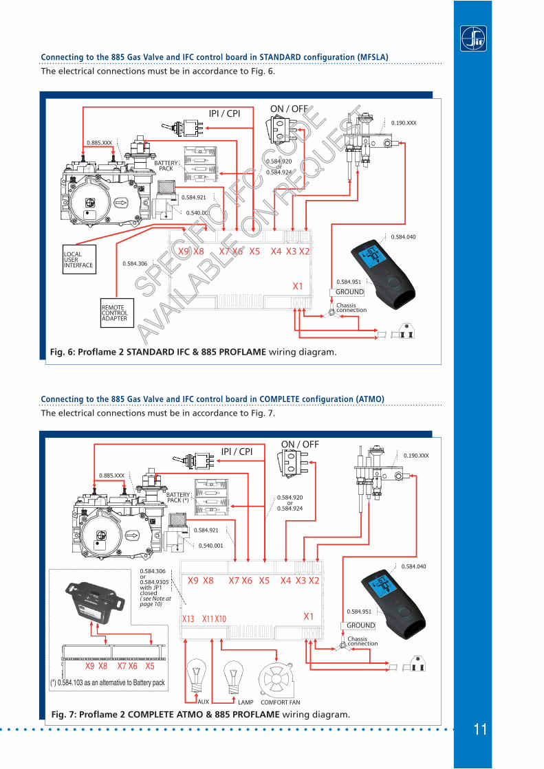
Connecting to the 885 Gas Valve and IFC control board in STANDARD configuration (MFSLA)
The electrical connections must be in accordance to Fig. 6.
# 2.160.031
0.885.XXX
0.190.XXX
0.584.951
0.584.920
0.584.306
0.584.040
0.540.001
0.584.921
0.584.952
Fig. 6: Proflame 2 STANDARD IFC & 885 PROFLAME wiring diagram.
0.885.XXX
0.190.XXX
0.584.951
0.584.92x
0.584.305
0.584.040
0.540.001
0.584.921
0.584.952
Fig. 7: Proflame 2 COMPLETE ATMO & 885 PROFLAME wiring diagram.
Connecting to the 885 Gas Valve and IFC control board in COMPLETE configuration (ATMO)
The electrical connections must be in accordance to Fig. 7.
0.584.951
0.584.040
GROUND
Chassisconnection
0.584.951
0.584.040
GROUND
Chassisconnection
0.584.920or
0.584.924
X9 X8 X7 X6 X5 X4 X3 X2
X1
ON / OFFIPI / CPI
BATTERYPACK
LOCALUSERINTERFACE
REMOTE CONTROL ADAPTER
SPECIFIC
IFCCODE
AVAILA
BLEON
REQUEST
0.584.920or
0.584.924
ON / OFFIPI / CPI
BATTERYPACK (*)
X9 X8 X7 X6 X5 X4 X3 X2
X1
0.584.306or0.584.9305with JP1 closed( see Note at page 10)
COMFORT FANLAMPAUX
(*) 0.584.103 as an alternative to Battery pack
X9 X8 X7 X6 X5
X13 X11 X10

12
Connecting to the 885 Gas Valve and IFC control board in COMPLETE configuration (FAN)
The electrical connections must be in accordance to Fig. 8.
Note: the models of IFC boards that can operate in either ATMO or in FAN mode, are confi gured in
the factory in ATMO mode (Jumper JP1 closed). To enable the FAN mode, it is necessary to
open the IFC removing the cover and than remove the jumper JP1 (JP1 open), see Picture and
Table below.
JP1 STATUS IFC board enabled mode
OPENFAN
CLOSED
ATMO
(DEFAULT)
0.885.XXX
0.190.XXX
0.584.951
0.584.92x
0.584.305
0.584.040
0.540.001
0.584.921
0.584.952
Fig. 8: Proflame 2 COMPLETE FAN & 885 PROFLAME wiring diagram.
0.584.951
0.584.040
GROUND
ChassisconnectionAUX
COMFORT FANLAMP
BURNER
(*) 0.584.103 as an alternative to Battery pack
X9 X8 X7 X6 X5
X9 X8 X7 X6 X5 X4 X3 X2
X13 X12 X11 X10 X1
JP1 = OPEN
ON / OFFIPI / CPI
BATTERYPACK (*)
13
OPERATING PROCEDURE FOR A BASIC
CONTROL SYSTEM
Before applying any power supply to the IFC board please verify that the electrical connections are in accordance to Fig. 5.
Initializing the System for the first time
Set the main burner ON/OFF command switch to the OFF position.If installed, set the pilot flame mode selector switch to the IPI position.Install 4 AA batteries into the battery holder, and respect the polarity indicated on the battery holder silkscreen. Connect the battery holder to the IFC main wiring harness.Connect the AC power supply to the IFC.
Setting the Appliance into Continuous Pilot ignition mode
If installed on the wirings, set the IPI/CPI Pilot Mode Switch to the CPI position (switch closed). At that point the IFC ignition board will immediately complete the ignition sequence for the Pilot Flame, and then will remain with the Pilot Flame ON, waiting for a command to ignite the Main Burner Flame.
Turning ON the Appliance
Close the ON/OFF command contact on the ON/OFF wires, and this will command the IFC ignition board to Turn-ON the appliance main burner.
Turning OFF the Appliance
Open the ON/OFF command contact on the ON/OFF wires, and this will command the IFC ignition board to Turn-OFF the appliance main burner.NOTE: if the Continuous Pilot ignition mode is selected, the Pilot Flame will remain ON. To also turn it completely OFF, switch the appliance into Intermittent Pilot ignition mode, so set the IPI/CPI Pilot Mode Switch to the IPI position (switch opened).
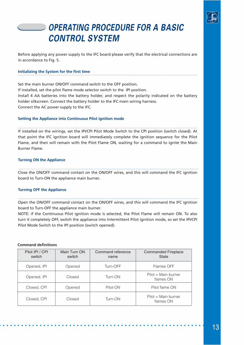
Command defi nitions
Pilot IPI / CPIswitch
Main Turn ONswitch
Command referencename
Commanded FireplaceState
Opened, IPI Opened Turn-OFF Flames OFF
Opened, IPI Closed Turn-ONPilot + Main burner
fl ames ON
Closed, CPI Opened Pilot-ON Pilot fl ame ON
Closed, CPI Closed Turn-ONPilot + Main burner
fl ames ON
14
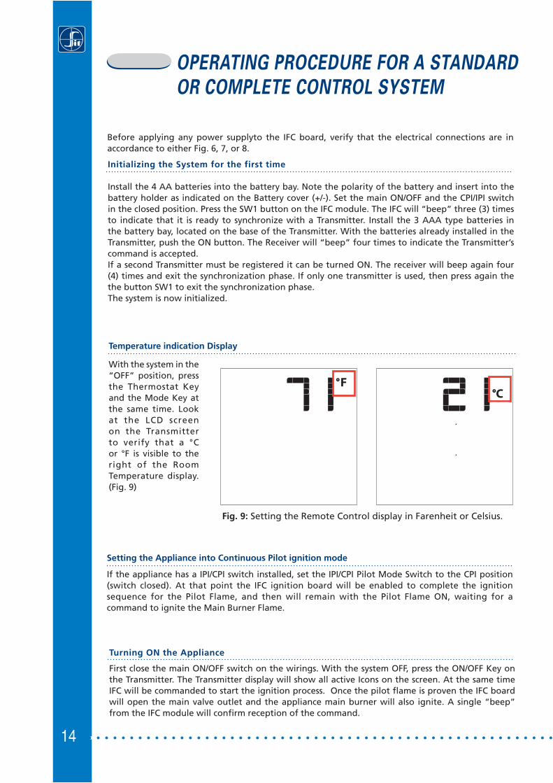
Temperature indication Display
With the system in the “OFF” position, press the Thermostat Key and the Mode Key at the same time. Look at the LCD screen on the Transmitter to verify that a °C or °F is visible to the right of the Room Temperature display. (Fig. 9)
OPERATING PROCEDURE FOR A STANDARD
OR COMPLETE CONTROL SYSTEM
Turning ON the Appliance
First close the main ON/OFF switch on the wirings. With the system OFF, press the ON/OFF Key on the Transmitter. The Transmitter display will show all active Icons on the screen. At the same time IFC will be commanded to start the ignition process. Once the pilot flame is proven the IFC board will open the main valve outlet and the appliance main burner will also ignite. A single “beep” from the IFC module will confirm reception of the command.
Initializing the System for the first time
Install the 4 AA batteries into the battery bay. Note the polarity of the battery and insert into the battery holder as indicated on the Battery cover (+/-). Set the main ON/OFF and the CPI/IPI switch in the closed position. Press the SW1 button on the IFC module. The IFC will “beep” three (3) times to indicate that it is ready to synchronize with a Transmitter. Install the 3 AAA type batteries in the battery bay, located on the base of the Transmitter. With the batteries already installed in the Transmitter, push the ON button. The Receiver will “beep” four times to indicate the Transmitter’s command is accepted. If a second Transmitter must be registered it can be turned ON. The receiver will beep again four (4) times and exit the synchronization phase. If only one transmitter is used, then press again the the button SW1 to exit the synchronization phase.The system is now initialized.
Setting the Appliance into Continuous Pilot ignition mode
If the appliance has a IPI/CPI switch installed, set the IPI/CPI Pilot Mode Switch to the CPI position (switch closed). At that point the IFC ignition board will be enabled to complete the ignition sequence for the Pilot Flame, and then will remain with the Pilot Flame ON, waiting for a command to ignite the Main Burner Flame.
Before applying any power supplyto the IFC board, verify that the electrical connections are in accordance to either Fig. 6, 7, or 8.
Fig. 9: Setting the Remote Control display in Farenheit or Celsius.

Turning OFF the Appliance
With the system ON, press the ON/OFF Key on the Transmitter. The Transmitter LCD display will only show the room temperature (Fig. 8). At the same time the IFC will be commanded to turn off the burner. Depending on the system mode (IPI or CPI) the pilot may shut off (IPI) or remain lit (CPI) and the appliance burner turns OFF. A single “beep” from the Receiver confirms reception of the command.
NOTE: see Continous Pilot/Intermittent Pilot (CPI/IPI) selection paragraph.
15
Fig. 8: Remote Control display.
Remote-Flame Control
The proflame has six (6) flame levels. With the system on, and the flame level at the maximum in the appliance, pressing the Down Arrow Key once will reduce the flame height by one step until the flame is turned off.The Up Arrow Key will increase the flame height each time it is pressed. If the Up Arrow Key is pressed while the system is on but the flame is off, the flame will come on in the high position. ( Fig. 8 & 9 ) A single “beep” will confirm reception of the command.
Fig. 8: Flame Off Flame Level 1
Fig. 9: Flame level 5 Flame Level Maximum

16
Room Thermostat ( Transmitter Operation)
The Remote Control can operate as a room thermostat. The thermostat can be set to a desired temperature to control the comfort level in a room.To activate this function, press the Thermostat Key (Fig. 1). The LCD display on the Transmitter will change to show that the room thermostat is “ON” and the set temperature is now displayed (Fig. 10). To adjust the set temperature, press the Up or Down Arrow Keys until the desired set temperature is displayed on the LCD screen of the Transmitter (Fig. 11).
Fig. 10 Fig. 11
SET TEMPERATURE
ROOM TEMPERATURE
Smart Thermostat (Transmitter Operation)
The Smart Thermostat function adjusts the flame height in accordance to the difference between the set point temperature and the actual room temperatures. As the room temperature gets closer to the set point the Smart Function will modulate the flame down. To activate this function, press the Thermostat Key (Fig. 1) until the word "SMART" appears to the right of the temperature bulb graphic (Fig. 12). To adjust the set temperature, press the Up or Down Arrow Keys until the desidered set temperature is displayed on the LCD screen of the Transmitter (Fig. 13).
Fig. 12: Smart flame function Fig. 13
17
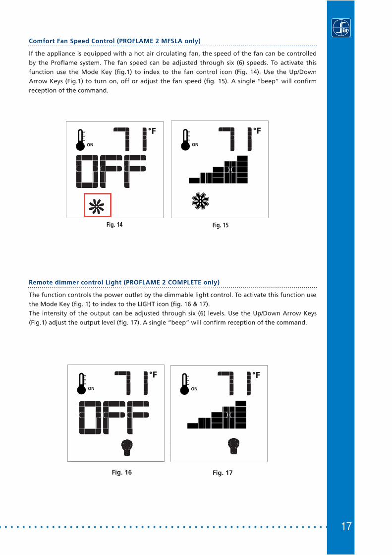
Comfort Fan Speed Control (PROFLAME 2 MFSLA only)
If the appliance is equipped with a hot air circulating fan, the speed of the fan can be controlled by the Proflame system. The fan speed can be adjusted through six (6) speeds. To activate this function use the Mode Key (fig.1) to index to the fan control icon (Fig. 14). Use the Up/Down Arrow Keys (Fig.1) to turn on, off or adjust the fan speed (fig. 15). A single “beep” will confirm reception of the command.
Fig. 14 Fig. 15
Remote dimmer control Light (PROFLAME 2 COMPLETE only)
The function controls the power outlet by the dimmable light control. To activate this function use the Mode Key (fig. 1) to index to the LIGHT icon (fig. 16 & 17).The intensity of the output can be adjusted through six (6) levels. Use the Up/Down Arrow Keys (Fig.1) adjust the output level (fig. 17). A single “beep” will confirm reception of the command.
Fig. 16 Fig. 17

18
Split Flow control
The secondary burner is controlled by the split Flow. To activate this function use the Mode Key (fig. 1) to index to the SPLIT FLOW mode icon (fig. 18 & 19).Pressing the Up Arrow Key will activate the secondary burner. Pressing the Down Arrow Key will turn the secondary burner off. A single “beep” will confirm the reception of the command.
Fig. 18 Fig. 19
Remote auxiliary relay control (PROFLAME 2 MFSLA only)
The auxiliary function controls the AUX relay outlet. To activate this function use the Mode Key (fig. 1) to index to the AUX icon (fig. 20 & 21).Pressing the Up Arrow Key will activate the outlet. Pressing the Down Arrow Key will turn the outlet off. A single “beep” will confirm the reception of the command.
Fig. 20 Fig. 21

19
This function will lock the keys to avoid unsupervised operation. To activate this function, press the MODE and UP keys at the same time (Fig. 24).To de-activate this function, press the MODE and UP keys at the same time.
Key lock
Fig. 24
Continous Pilot/Intermittent Pilot (CPI/IPI) selection
With the system in "OFF" position press the Mode Key (fig. 1) to index to the CPI mode icon (fig. 22 & 23).Pressing the Up Arrow Key will activate the Continous Pilot Ignition mode (CPI). Pressing the Down Arrow Key will return to IPI. A single “beep” will confirm the reception of the command.
NOTE: If the system is equipped with a CPI/IPI toggle switch:• Set the CPI/IPI switch to CPI position(switch closed) to enable remote CPI selection. • Set the CPI/IPI switch to IPI position (switch open) to disable remote CPI selection.
The system will now work in IPI mode only regardless of the selection on the remote control hand set.
Fig. 22 Fig. 23
20
APPENDIX
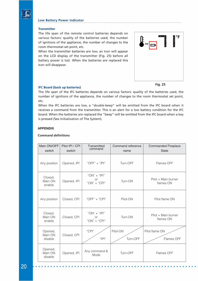
TransmitterThe life span of the remote control batteries depends on various factors: quality of the batteries used, the number of ignitions of the appliance, the number of changes to the room thermostat set point, etc.When the transmitter batteries are low, an Icon will appear on the LCD display of the transmitter (Fig. 25) before all battery power is lost. When the batteries are replaced this Icon will disappear.
IFC Board (back up batteries)The life span of the IFC batteries depends on various factors: quality of the batteries used, the number of ignitions of the appliance, the number of changes to the room thermostat set point, etc.When the IFC batteries are low, a "double-beep” will be emitted from the IFC board when it receives a command from the transmitter. This is an alert for a low battery condition for the IFC board. When the batteries are replaced the “beep” will be emitted from the IFC board when a key is pressed (See Initialization of The System).
Low Battery Power indicator
Fig. 25
Command defi nitions
Main ON/OFF
switch
Pilot IPI / CPI
switch
Transmittedcommand
Command reference
name
Commanded Fireplace
State
Any position Opened, IPI “OFF” + “IPI” Turn-OFF Flames OFF
Closed,Main ON enable
Opened, IPI
“ON” + “IPI” or
“ON” + “CPI”Turn-ON
Pilot + Main burnerfl ames ON
Any position Closed, CPI “OFF” + “CPI” Pilot-ON Pilot fl ame ON
Closed,Main ON enable
Closed, CPI“ON” + “IPI”
or“ON” + “CPI”
Turn-ONPilot + Main burner
fl ames ON
Opened,Main ON disable
Closed, CPI “CPI”
“IPI”
Pilot-ON
Turn-OFF
Pilot fl ame ON
Flames OFF
Opened,Main ON disable
Opened, IPIAny command &
ModeTurn-OFF Flames OFF

21
DIMENSIONAL DRAWINGS
PROFLAME Transmitter
140
37 71
152
63
63
26
26
Ø3Ø3
Dimensions are in millimeters
PROFLAME Wall Mount Transmitter
Dimensions are in millimeters
22
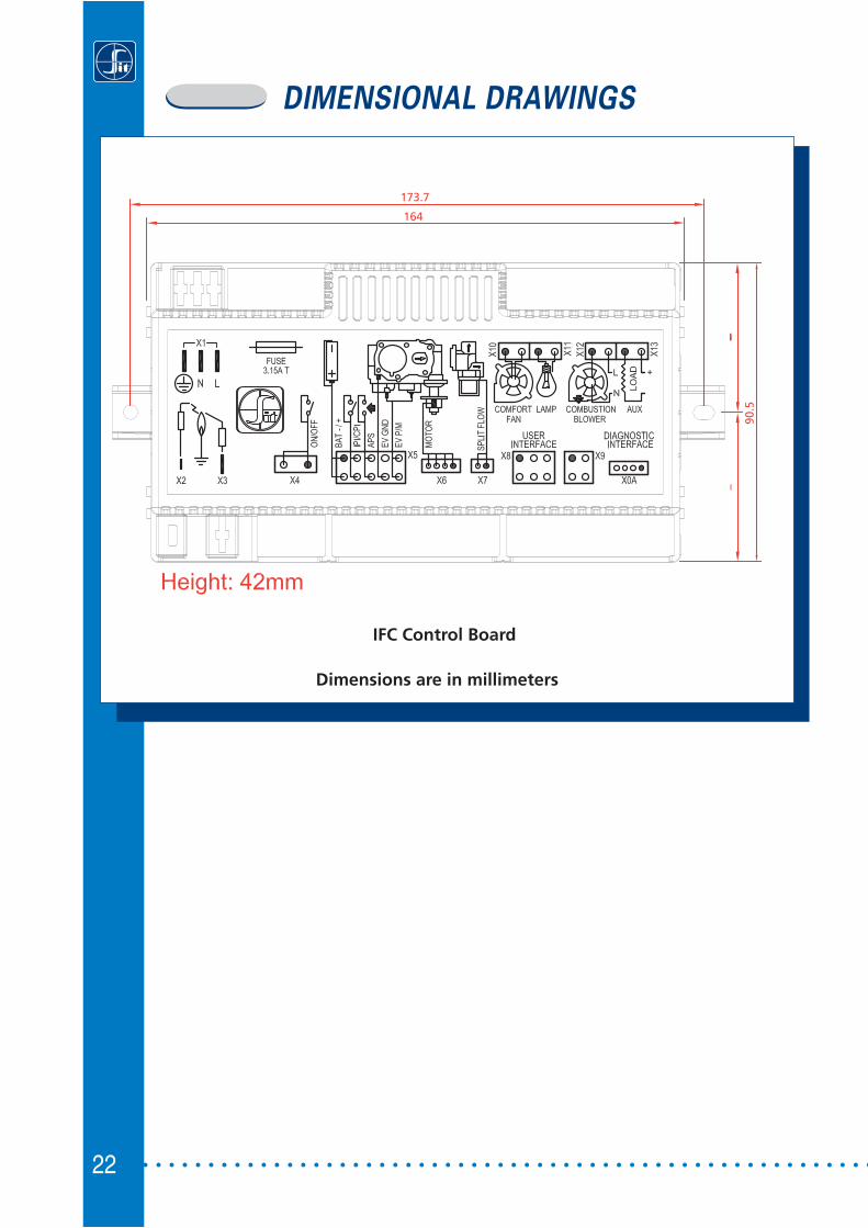
DIMENSIONAL DRAWINGS
IFC Control Board
173.7
164
90.5
Dimensions are in millimeters

23

SIT S.p.A.Viale dell’Industria 31-3335129 PADOVA - ITALY
Tel. +39/049/829.31.11, Fax +39/049/807.00.93www.sitgroup.it - e-mail: [email protected]


![Basic is-Is[2] Complete](https://static.documents.pub/doc/80x56/577cc79d1a28aba711a178fe/basic-is-is2-complete.jpg)

