P.Ravindran, Nanomaterials and Nanotechnology, Spring 2016: Nanocomposites http://folk.uio.no/ravi/cutn/NMNT Prof.P. Ravindran, Department of Physics, Central University of Tamil Nadu, India & Center for Materials Science and Nanotechnology, University of Oslo, Norway Nanocomposites 1
Transcript
P.Ravindran, Nanomaterials and Nanotechnology, Spring 2016: Nanocomposites
http://folk.uio.no/ravi/cutn/NMNT
Prof.P. Ravindran, Department of Physics, Central University of Tamil
Nadu, India
&Center for Materials Science and Nanotechnology,
University of Oslo, Norway
Nanocomposites
1
P.Ravindran, Nanomaterials and Nanotechnology, Spring 2016: Nanocomposites
Nanocomposites
Nanocomposites are a broad range of materials consisting of
two or more components, with at least one component having
dimensions in the nm regime (i.e. between 1 and 100 nm)
Typically consists of a macroscopic matrix or host with the
addition of nanometer-sized particulates or filler
Filler can be: 0 D (nano-particles), 1 D (nano-wires, nano-
tubes), 2 D (thin film coatings, quantum wells), or 3 D
(embedded networks, co-polymers)
e.g. CNTs in a polymer matrix
2
P.Ravindran, Nanomaterials and Nanotechnology, Spring 2016: Nanocomposites
Common matrix materials are rubber, engineering plastics
or polyolefines with a small content of nanoscale materials.
Usually less than 5% of nanomaterials are used to improve
thermal or mechanical properties
Typical ways to produce Nanocomposites are In-Situ-
Polymerization and melt blending / compounding
Three types of nano material are commonly melt blended
with plastics: Nano clay, nano tubes and nano scale particles
(SiO2, ZrO2, Ag)
Nanocomposites3
P.Ravindran, Nanomaterials and Nanotechnology, Spring 2016: Nanocomposites
P.Ravindran, Nanomaterials and Nanotechnology, Spring 2016: Nanocomposites
Apart from the properties of the individual components in a nanocomposite, the interfaces play an important role in enhancing or limiting overall properties of system
Controls the degree of interaction between the filler and the matrix and thus influences the properties
Alters chemistry, polymer chain mobility, degree of cure, crystallinity, etc.
Nano Effect7
P.Ravindran, Nanomaterials and Nanotechnology, Spring 2016: Nanocomposites
Surface and interface properties (e.g. adhesive and frictional forces) become
critical as materials become smaller
High surface area materials have applications in: energy storage, catalysis,
battery/capacitor elements, gas separation and filtering, biochemical
separations, etc.
1 10 100 1000
0
20
40
60
80
0
1x10¹⁰
2x10¹⁰
3x10¹⁰
4x10¹⁰
5x10¹⁰
To
tal N
o. o
f A
tom
s
Su
rfac
e to
Vo
lum
e A
tom
ic R
atio
(%
)
Cube Side, (nm)
Si Cube with (100)-Directed Faces
Si Cube
Volume
Surface-
to-
Volume
Atomic
Ratio
(1 mm)3 0.081%
(100 nm)3 0.81%
(10 nm)3 8.1%
(5 nm)3 16%
(2 nm)3 41%
(1 nm)3 82%
Surface to Volume Ratio 8
P.Ravindran, Nanomaterials and Nanotechnology, Spring 2016: Nanocomposites
Interaction of phases at interface is key:
Adding nanotubes to a polymer can improve the strength (due to
superior mechanical properties of the NTs)
A non-interacting interface serves only to create weak regions in the
composite resulting in no enhancement
Most nano-particles do not scatter light significantly
Possible to make composites with altered electrical or mechanical
properties while retaining optical clarity
CNTs and other nano-particles are often essentially defect free
Nanocomposites
Other Properties and Benefits
9
P.Ravindran, Nanomaterials and Nanotechnology, Spring 2016: Nanocomposites
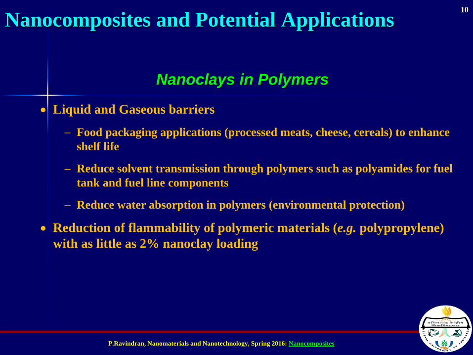
Liquid and Gaseous barriers
Food packaging applications (processed meats, cheese, cereals) to enhance
shelf life
Reduce solvent transmission through polymers such as polyamides for fuel
tank and fuel line components
Reduce water absorption in polymers (environmental protection)
Reduction of flammability of polymeric materials (e.g. polypropylene)
with as little as 2% nanoclay loading
Nanocomposites and Potential Applications
Nanoclays in Polymers
10
P.Ravindran, Nanomaterials and Nanotechnology, Spring 2016: Nanocomposites
Nanotubes in Polymers
High strength materials
Modulus as high as 1 TPa and strengths as high as 500
GPa
Significant weight reductions for similar performance,
greater strength for similar dimensions (military and
aerospace applications)
Electrically conductive polymers
11
P.Ravindran, Nanomaterials and Nanotechnology, Spring 2016: Nanocomposites
Several techniques used for nanocomposites including:
Nuclear Magnetic Resonance
Neutron Scattering Methods
X-Ray Diffraction
Atomic Force Microscopy
Scanning Electron Microscopy
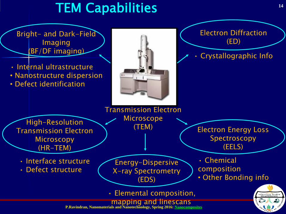
Transmission Electron Microscopy
Transmission Electron Microscopy and X-ray Diffraction are the most
common techniques
Nanocomposites Characterization Techniques
12
P.Ravindran, Nanomaterials and Nanotechnology, Spring 2016: Nanocomposites
Secondary Electron Imaging(SEI)
Transmitted Electron Imaging(TEI)
Backscattered Imaging(BSI)
• Surface Topography, Morphology, Particle Sizes, etc.
• Compositional Contrast
• Internal ultrastructure
Energy-Dispersive X-ray Spectrometry
(EDS)
• Elemental composition, mapping and linescans
• Crystallographic Info
Electron Backscattered Electron Diffraction
(EBSD)
SEM Capabilities
Scanning Electron Microscope(SEM)
13
P.Ravindran, Nanomaterials and Nanotechnology, Spring 2016: Nanocomposites