39
Chameleon Manual

Chameleon Manual

Page 2
Onsite training is available and telephone technical support with optional remote access for further assistance is all part of the support we can offer. For further details and assistance contact us on 01254 883348 or email us on
www.progeny.co.uk
Document Numbers: 2159 2159-LP 2159-VR
Date: 16-02-2007 Issue: 08
:
EMC Certificate Number
A8281
Copyright BSB Electronics Ltd 2002 All rights reserved.
Page 3
CONTENTS INTRODUCTION 5
SYSTEM CONFIGURATIONS 6 SINGLE DOOR 6 SINGLE DOOR & CONTROL 6 TWO DOOR 6
OPERATION 7 INDICATORS 7 SOUND 7 USING PROXIMITY CARD 8 USING ACCESS CODES 8 HOLDING A CHANNEL OPEN 8 TOGGLE MODE 8 ALARMS 8
PDO 8 DOOR FORCED 9 DURESS 9
PROGRAMMING 10 PROXIMITY FUNCTIONS 12
SITE CODE 12 ADDING CARDS 13 REMOVING CARDS 155 TESTING CARDS 177 PROXIMITY LOCK RELEASE TIME 18
ACCESS CODE FUNCTIONS 199 ADDING ACCESS CODES 19 REMOVING ACCESS CODES 20 CODE LOCK RELEASE TIME 21 PENALTY TIME 222
ALARM & PROGRAMMING FUNCTIONS 233 PROLONGED DOOR OPEN (PDO) 233 PROGRAMMING CODE 244
GUEST CARD FUNCTIONS 255 ADD GUEST CARDS 25 REMOVE GUEST CARDS 266

Page 4
ENGINEERING SETTINGS 277 KEY 9 "FULL RESET" 277 KEY 1 "CLEAR CARDS & GUESTS" 277 KEY 2 "CLEAR CARDS, GUESTS & ACCESS CODES" 277 KEY 3 "CLEAR ACCESS CARDS 277 KEY 7 "PART RESET & DURESS OFF" 277 KEY 8 "PART RESET & DURESS ON" 277 KEY 5 "CARD & CODE MODE" 277 KEY 6 "CARD OR CODE MODE" (Default) 277
INSTALLATION 278 MOUNTING 278 WIRING DIAGRAMS 288
PSU & READER 288 LOCKS 299 REQUEST TO EXIT 322 CALL OUTPUT 333 PDO & DOOR FORCED ALARMS 344
QUICK START PROGRAMMING GUIDE 355 SPECIFICATION 366
PROXIMITY CHANNEL 366 CODE CHANNEL 366 CONTROLLER 37 POWER SUPPLY 388
Page 5
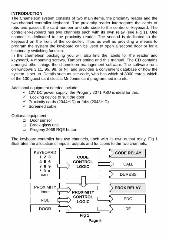
INTRODUCTION The Chameleon system consists of two main items, the proximity reader and the two-channel controller-keyboard. The proximity reader interrogates the cards or fobs and passes the card number and site code to the controller-keyboard. The controller-keyboard has two channels each with its own relay (see Fig 1). One channel is dedicated to the proximity reader. The second is dedicated to the keyboard on the front of the controller. Thus as well as providing a means to program the system the keyboard can be used to open a second door or for a secondary switching function. In the chameleon packaging you will also find the labels for the reader and keyboard, 4 mounting screws, Tamper spring and this manual. The CD contains amongst other things the chameleon management software. The software runs on windows 3.11, 95, 98, or NT and provides a convenient database of how the system is set up. Details such as site code, who has which of 8000 cards, which of the 100 guest card slots is Mr Jones card programmed into etc. Additional equipment needed include:
12V DC power supply, the Progeny 2071 PSU is ideal for this. Locking device to suit the door Proximity cards (2044HID) or fobs (2043HID) Screened cable.
Optional equipment:
Door sensor Break glass unit Progeny 2068 RQE button
The keyboard-controller has two channels, each with its own output relay. Fig 1 illustrates the allocation of inputs, outputs and functions to the two channels.
Fig 1
KEYBOARD 1 2 3 4 5 6 7 8 9 * 0 # CALL
CODE
CONTROL
LOGIC
CODE RELAY
CALL
DURESS
PROXIMITY Input
PROXIMITY CONTROL
LOGIC RQE
DOOR sensor
PROX RELAY
PDO
DF
Page 6
The "CALL" and "DURESS" outputs are associated with the keyboard or "Code" channel. Note that the RQE and Door sensor input are only available for the "Proximity" channel. The arrow linking the CODE CONTROL and PROXIMITY CONTROL blocks indicates that the two channels can be configured to work together as CARD & CODE.
SYSTEM CONFIGURATIONS Listed below are some of the many configurations that can be achieved using the chameleon system.
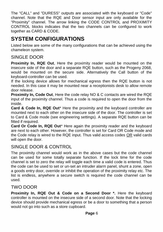
SINGLE DOOR
Proximity In, RQE Out, Here the proximity reader would be mounted on the insecure side of the door and a separate RQE button, such as the Progeny 2068, would be mounted on the secure side. Alternatively the Call button of the keyboard-controller can be used. If the locking device allows for mechanical egress then the RQE button is not needed. In this case it may be mounted near a receptionists desk to allow remote door release. Proximity In, Code Out, Here the code relay NO & C contacts are wired the RQE input of the proximity channel. Thus a code is required to open the door from the inside. Card & Code In, RQE Out* Here the proximity and the keyboard controller are mounted next to each other on the insecure side of the door. The controller is set to Card & Code mode (see engineering settings). A separate RQE button can be fitted if required. Card Or Code In, RQE Out* Here again the proximity reader and the keyboard are next to each other. However, the controller is set for Card OR Code mode and the Code relay is wired to the RQE input. Thus valid access codes OR valid cards will open the door.
SINGLE DOOR & CONTROL
The proximity channel would work as in the above cases but the code channel can be used for some totally separate function. If the lock time for the code channel is set to zero the relay will toggle each time a valid code is entered. Thus the code can be used to set or un-set an intruder alarm panel, shunt a zone, open a goods entry door, override or inhibit the operation of the proximity relay etc. The list is endless, anywhere a secure switch is required the code channel can be used.
TWO DOOR
Proximity In, RQE Out & Code on a Second Door *. Here the keyboard controller is mounted on the insecure side of a second door. Note that the locking device should provide mechanical egress or be a door to something that a person would not go into such as a store cupboard.

Page 7
* Note when using the keyboard half of the system on the insecure side of the door it is important to remember that the controller is built in to the keyboard. This means that a potential intruder could prise this unit off the wall and "hot wire" the door release. To help prevent this the 2159-KB has a tamper switch built in. Fit the tamper spring and wire the tamper connections to the 24hr loop of an intruder alarm system.
OPERATION
INDICATORS A coloured indicator is provided for each channel. The colours of these indicators have the following meanings.
LED Colour Meaning
Red Lock Closed
Green Lock Open
Amber PDO Alarm (Proximity only)
Flashing Off Programming
Short blink to Off Keyboard Key Push
SOUND Sound is used to give the user additional feedback on the status of the controller and progress during programming.
Sound Meaning
Continuous Two Tone, High Volume PDO Alarm
Four Notes “Low – High – Low – High” Programming Mode
Two Notes “Low – High” Confirm Programming Change
Two Notes “High – Low “ Programming Error
Single Short Note “High” Keyboard Key Push
Fast Trill sound Card disabled
Slow warble sound Card has wrong site code & is not a guest
Tic Tic Tic Memory programming in progress
Note: The sounds from the keyboard controller can be annoying if located in earshot. Pressing 8 and 9 together will mute the keyboard units sounder. However the sounder will re activate when the * key is pressed. Note that this will not mute the PDO alarm sound.

Page 8
USING PROXIMITY CARD The proximity card or key fobs simply needs to be presented to the reader. The readers LED will give a brief blink to green to indicate the
card has been read. If the card is programmed into the system the lock will release for the pre-set duration.
USING ACCESS CODES Access codes can be four, five or six digits in length. To operate the code channel simply enter one of the programmed access codes. If a correct code is entered, the code LED will change to green and the code output relay will activate. Access codes can be modified to indicate Duress. Note this feature must be enabled if required. See “RESTORING FACTORY DEFAULT SETTINGS” later in this manual.
HOLDING A CHANNEL OPEN If a lock timer is programmed for timed operation, the operator can override this and hold the output open. To do this, simply present a valid proximity card or enter a valid access code. Once the output is activated and the LED indicator is showing green, push and hold the 2 & 3 keys as a pair. This will hold open proximity relay. Enter a valid access code and press 1 & 2 keys to latch the code relay. To cancel the latched state of a channel simply present a card or enter a valid access code again. In the case of the proximity channel operating the RQE input will also cancel the latch.
TOGGLE MODE If the lock time for a particular channel has been set to zero then each time a valid card is presented or correct code is entered, the output relay will “Toggle” to the opposite state. Each channel has its own lock time thus either or both channels can be selected to “toggle” or “timed” operation. One channel can be used to open a door, and the other channel used to turn on and off a piece of equipment.
ALARMS
PDO
The purpose of the Prolonged Door Open (PDO) alarm is to act as a reminder that a door is a security door and should not be wedged or held open for too long. If the door sensor has been connected then each time the door is detected
HOLD OPEN CODE RELAY HOLD OPEN PROX RELAY
1 2 3 2
Page 9
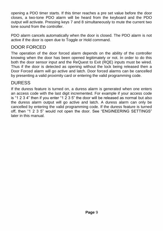
opening a PDO timer starts. If this timer reaches a pre set value before the door closes, a two-tone PDO alarm will be heard from the keyboard and the PDO output will activate. Pressing keys 7 and 8 simultaneously to mute the current two tone sound from the controller. PDO alarm cancels automatically when the door is closed. The PDO alarm is not active if the door is open due to Toggle or Hold command.
DOOR FORCED
The operation of the door forced alarm depends on the ability of the controller knowing when the door has been opened legitimately or not. In order to do this both the door sensor input and the ReQuest to Exit (RQE) inputs must be wired. Thus if the door is detected as opening without the lock being released then a Door Forced alarm will go active and latch. Door forced alarms can be cancelled by presenting a valid proximity card or entering the valid programming code.
DURESS
If the duress feature is turned on, a duress alarm is generated when one enters an access code with the last digit incremented. For example if your access code is “1 2 3 4” then if you enter “1 2 3 5” the door will be released as normal but also the duress alarm output will go active and latch. A duress alarm can only be cancelled by entering the valid programming code. If the duress feature is turned off, then “1 2 3 5” would not open the door. See “ENGINEERING SETTINGS” later in this manual.
Page 10
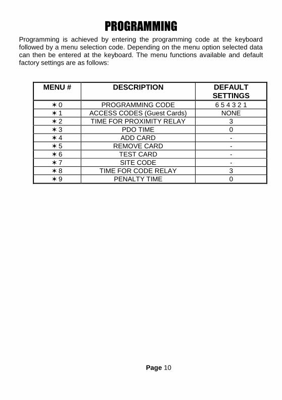
PROGRAMMING Programming is achieved by entering the programming code at the keyboard followed by a menu selection code. Depending on the menu option selected data can then be entered at the keyboard. The menu functions available and default factory settings are as follows:
MENU # DESCRIPTION DEFAULT SETTINGS
0 PROGRAMMING CODE 6 5 4 3 2 1
1 ACCESS CODES (Guest Cards) NONE
2 TIME FOR PROXIMITY RELAY 3
3 PDO TIME 0
4 ADD CARD -
5 REMOVE CARD -
6 TEST CARD -
7 SITE CODE -
8 TIME FOR CODE RELAY 3
9 PENALTY TIME 0

Page 11
Each menu is described in detail in the following sections. The general programming procedure is shown below:
6 5 4 3 2 1
2
#
Programming Tone & Flashing LED’s
Enter Programming code
Enter Menu Number
Press # to finish
3
Enter new value.
A rising two-tone note indicates SUCCESS.
A falling two-tone note indicates ERROR.
Press to select a new menu function.
Programming Tone & Flashing LED for
that channel

Page 12
PROXIMITY FUNCTIONS The site code is not printed on the cards or fobs but is documented on a cross-reference list provided with the cards. Keep this number safe in case additional cards need to be ordered later
SITE CODE
6 5 4 3 2 1
7
#
Enter Programming code
Select Menu 7, “Site Code”
Press to select a new menu function.
Press # to finish
*
6032 Enter four digits

Page 13
ADDING CARDS
Note that the proximity cards have serial number printed on them. This should be used with the cross-reference list, provided with cards, to determine the actual card number.
Single card:
6 5 4 3 2 1
4
#
Enter Programming code
Select Menu 4, “Add Card”
Press # to finish
124 Enter card number Or Present Card

Page 14
Block of cards
6 5 4 3 2 1
4
#
Enter Programming code
Select Menu 4, “Add Card”
Press # to finish
101 Enter first card number or present the first card
*
200
Enter * as separator
Enter last card number or present the last card

Page 15
REMOVING CARDS
Single card
6 5 4 3 2 1
5
#
Enter Programming code
Select Menu 5, “Remove Card”
Press # to finish
124 Enter card number or present the card
Page 16
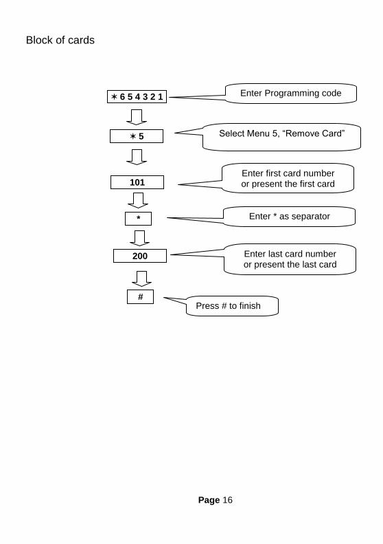
Block of cards
6 5 4 3 2 1
5
#
Enter Programming code
Select Menu 5, “Remove Card”
Press # to finish
101 Enter first card number or present the first card
*
200
Enter * as separator
Enter last card number or present the last card
Page 17
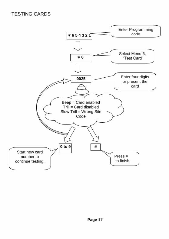
TESTING CARDS
6 5 4 3 2 1
6
#
Enter Programming code
Select Menu 6, “Test Card”
Start new card number to
continue testing.
Press # to finish
0 to 9
0025 Enter four digits or present the
card
Beep = Card enabled Trill = Card disabled
Slow Trill = Wrong Site Code
Page 18
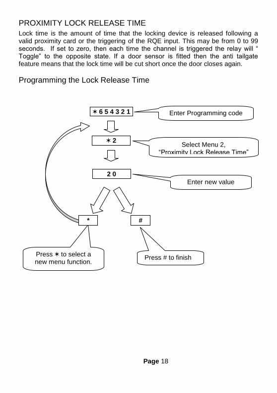
PROXIMITY LOCK RELEASE TIME
Lock time is the amount of time that the locking device is released following a valid proximity card or the triggering of the RQE input. This may be from 0 to 99 seconds. If set to zero, then each time the channel is triggered the relay will “ Toggle” to the opposite state. If a door sensor is fitted then the anti tailgate feature means that the lock time will be cut short once the door closes again.
Programming the Lock Release Time
6 5 4 3 2 1
2
#
Enter Programming code
Select Menu 2, “Proximity Lock Release Time”
Press to select a new menu function.
Press # to finish
*
2 0
Enter new value
Page 19
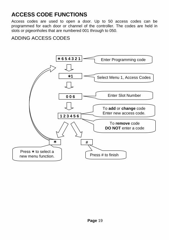
ACCESS CODE FUNCTIONS Access codes are used to open a door. Up to 50 access codes can be programmed for each door or channel of the controller. The codes are held in slots or pigeonholes that are numbered 001 through to 050.
ADDING ACCESS CODES
6 5 4 3 2 1
1
Enter Programming code
Select Menu 1, Access Codes
Press to select a new menu function.
Press # to finish
1 2 3 4 5 6
To add or change code Enter new access code.
0 0 6 Enter Slot Number
To remove code
DO NOT enter a code
#

Page 20
REMOVING ACCESS CODES
Removing Individual Access Codes
Follow the same procedure as for adding access codes except after select the slot containing the access code in question simply press or #. This will clear the code contained at that slot.
Removing All Cards and Access Codes
All access codes can be removed by removing power to the controller then while holding the number 2 key apply power only releasing the key when a beep is heard from the control unit.
Removing All Cards
All cards can be removed by removing power to the controller then while holding the number 1 key apply power only releasing the key when a beep is heard from the control unit.
Removing All Codes
All access codes can be removed by removing power to the controller then while holding the number 3 key apply power only releasing the key when a beep is heard from the control unit.

Page 21
CODE LOCK RELEASE TIME
Lock time is the amount of time that the locking device is released following a valid access code. This may be from 0 to 99 seconds. If set to zero, then each time the channel is triggered the relay will “ Toggle” to the opposite state.
Programming the Lock Release Time
6 5 4 3 2 1
8
#
Enter Programming code
Select Menu 8, Code Lock Time
Press to select a new menu function.
Press # to finish *
2 0 Enter new value

Page 22
PENALTY TIME
This feature can slow persons, trying to gain access by using successive codes, down. As soon as an incorrect code is detected at the keyboard this penalty time is invoked, preventing any further access attempts until the timer elapses. The factory set default penalty time is 0 seconds (Disabled).
Programming the Penalty Time
6 5 4 3 2 1
9
#
Enter Programming code
Select Menu 9, Penalty Time A
Press to select a new menu function.
Press # to finish
1 0 Enter new value

Page 23
ALARM & PROGRAMMING FUNCTIONS
PROLONGED DOOR OPEN (PDO)
There are connections on the control unit to allow the monitoring of the door open status. PDO is the amount of time the door may be open before triggering an audible alarm from the control unit. This may be from 0 to 99 seconds. If set to zero PDO sensing for that channel is disabled.
Programming PDO Time
Pressing 7 and 8 together will mute the integral PDO alarm sounder. This does not affect the PDO alarm output. The PDO will however re sound on the next alarm occurrence. To disable the PDO sound and output permanently, program the PDO time to zero.
6 5 4 3 2 1
3
#
Select Menu 3, PDO Time
Press to select a new
menu function.
Press # to finish
1 5 Enter new value
Enter Programming code

Page 24
PROGRAMMING CODE
The programming code is the means by which the systems operator gains access to the programming functions. This is a 6-digit number and can be changed by using the following procedure.
Changing the Programming Code
6 5 4 3 2 1
0
#
Enter Programming code
Enter Menu Number
Press to select a new menu function.
Press # to finish
9 8 7 6 5 4 Enter New Code Again
9 8 7 6 5 4 Enter New Code
Page 25
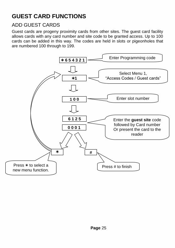
GUEST CARD FUNCTIONS
ADD GUEST CARDS
Guest cards are progeny proximity cards from other sites. The guest card facility allows cards with any card number and site code to be granted access. Up to 100 cards can be added in this way. The codes are held in slots or pigeonholes that are numbered 100 through to 199.
6 5 4 3 2 1
1
#
Enter Programming code
Select Menu 1, “Access Codes / Guest cards”
Press to select a new menu function.
Press # to finish
0 0 0 1
1 0 0 Enter slot number
6 1 2 5 Enter the guest site code followed by Card number Or present the card to the
reader

Page 26
REMOVE GUEST CARDS
6 5 4 3 2 1
1
#
Enter Programming code
Select Menu 1, “Access Codes / Guest cards”
Press to select a new menu function.
Press # to finish
1 0 0 Enter slot number

Page 27
ENGINEERING SETTINGS There are a number of engineering options that can be programmed at commissioning time. These options include:
Full factory reset
Clearing proximity cards from memory
Clearing access codes from memory
Turning the Duress feature On or OFF
Selecting "CARD & CODE" or "CARD OR CODE" mode The procedure consists of first removing power to the controller, then while holding one of the keys, re-apply power. Release the key when a beep is heard from the control unit.
KEY 9 "FULL RESET"
This resets all parameters to the factory default values and removes all Cards, Guest Cards and Access Codes.
KEY 1 "CLEAR CARDS & GUESTS"
KEY 2 "CLEAR CARDS, GUESTS & ACCESS CODES"
KEY 3 "CLEAR ACCESS CARDS
KEY 7 "PART RESET & DURESS OFF"
KEY 8 "PART RESET & DURESS ON"
KEY 5 "CARD & CODE MODE"
When this mode is selected a valid proximity card AND a valid access code must be entered for the Proximity relay to be activated. Note that in this mode the Code relay has no function.
KEY 6 "CARD OR CODE MODE" (Default)
In this mode, a proximity card or access code operate the respective relay. Note if the code and the proximity channels are to open the same locking device use the following wiring diagrams for the lock circuit.
INSTALLATION
MOUNTING The controller and reader should be mounted at height that is convenient for all users of the system (between 1.2 and 1.5m from the floor).
Page 28
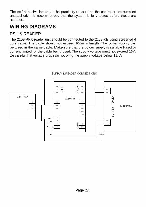
The self-adhesive labels for the proximity reader and the controller are supplied unattached. It is recommended that the system is fully tested before these are attached.
WIRING DIAGRAMS
PSU & READER
The 2159-PRX reader unit should be connected to the 2159-KB using screened 4 core cable. The cable should not exceed 100m in length. The power supply can be wired in the same cable. Make sure that the power supply is suitable fused or current limited for the cable being used. The supply voltage must not exceed 16V. Be careful that voltage drops do not bring the supply voltage below 11.5V.
NO
C
NC
DF
DO
DR
E
0V
0V
+V
C
NC
DUR
CALL
RQE
D1
PDO
NC
C
NO
CO
DE
PR
OX
TA
MP
2159 KB
2159 PRX
0V
+12V
DO
D1
SU
PP
LY
DA
TA
SUPPLY & READER CONNECTIONS
0V
+12V
E
SCREEN
12V PSU

Page 29
LOCKS
Locking devices fall into two main categories: "Fail Secure" and "Fail Open". The fail secure type requires power to release the door while the fail open type require power to hold the door locked. The following diagrams show the connection, to the Proximity channel, of these two types of locking device. The same principle of connection can be applied to the Code channel.
NO
C
NC
DF
DO
DR
E
0V
0V
+V
C
NC
DUR
CALL
RQE
D1
PDO
NC
C
NO
CO
DE
PR
OX
TA
MP
2159 KB
LOCK CONNECTION (FAIL SECURE)
0V
+12V
E
12V PSU+VE
-VE
STRIKE
DIODE

Page 30
NO
C
NC
DF
DO
DR
E
0V
0V
+V
C
NC
DUR
CALL
RQE
D1
PDO
NC
C
NO
CO
DE
PR
OX
TA
MP
2159 KB
LOCK CONNECTION (FAIL SAFE)
0V
+12V
E
12V PSU +VE
-VE
BREAK
GLASS
MAGNET
Page 31
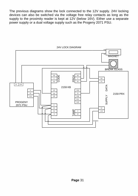
The previous diagrams show the lock connected to the 12V supply. 24V locking devices can also be switched via the voltage free relay contacts as long as the supply to the proximity reader is kept at 12V (below 16V). Either use a separate power supply or a dual voltage supply such as the Progeny 2071 PSU.
NO
C
NC
DF
DO
DR
E
0V
0V
+V
C
NC
DUR
CALL
RQE
D1
PDO
NC
C
NO
CO
DE
PR
OX
TA
MP
2159 KB
2159 PRX
0V
+12V
DO
D1
SU
PP
LY
D
AT
A
24V LOCK DIAGRAM
0V
+12V
E
SCREEN
PROGENY
2071 PSU
+VE
-VE
BREAK GLASS
MAGNET
+24V0V

Page 32
REQUEST TO EXIT
(Using "Call" Button / External)
NO
C
NC
DF
DO
DR
E
0V
0V
+V
C
NC
DUR
CALL
RQE
D1
PDO
NC
C
NO
CO
DE
PR
OX
TA
MP
2159 KB
REQUEST TO EXIT OPTIONS
NO
C
NC
DF
DO
DR
E
0V
0V
+V
C
NC
DUR
CALL
RQE
D1
PDO
NC
C
NO
CO
DE
PR
OX
TA
MP
2159 KB
CONNECTING A REMOTE BUTTONUSING THE CALL BUTTON AS RQE
REMOTE
BUTTON
(NO)

Page 33
CALL OUTPUT
The 2159-KB keyboard has a call button. If this unit is mounted on the secure side of a door, it may be used to ring a visitor bell or chime.
NO
C
NC
DF
DO
DR
E
0V
0V
+V
C
NC
DUR
CALL
RQE
D1
PDO
NC
C
NO
CO
DE
PR
OX
TA
MP
2159 KB
CONNECTING A REMOTE VISITOR CHIME
0V
+12V
E
12V PSU
REMOTE
CHIME
-VE
+VE
Page 34
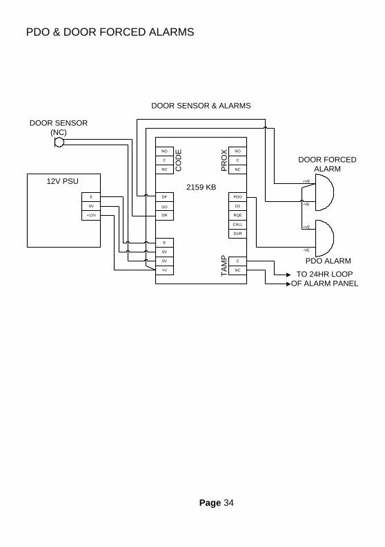
PDO & DOOR FORCED ALARMS
NO
C
NC
DF
DO
DR
E
0V
0V
+V
C
NC
DUR
CALL
RQE
D1
PDO
NC
C
NO
CO
DE
PR
OX
TA
MP
2159 KB
DOOR SENSOR & ALARMS
0V
+12V
E
12V PSU
DOOR FORCED
ALARM
-VE
+VE
PDO ALARM
+VE
-VE
DOOR SENSOR
(NC)
TO 24HR LOOP
OF ALARM PANEL
Page 35
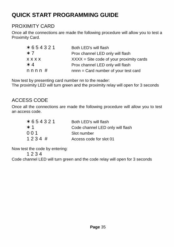
QUICK START PROGRAMMING GUIDE
PROXIMITY CARD
Once all the connections are made the following procedure will allow you to test a Proximity Card.
6 5 4 3 2 1 Both LED's will flash
7 Prox channel LED only will flash
x x x x XXXX = Site code of your proximity cards
4 Prox channel LED only will flash
n n n n # nnnn = Card number of your test card
Now test by presenting card number nn to the reader: The proximity LED will turn green and the proximity relay will open for 3 seconds
ACCESS CODE
Once all the connections are made the following procedure will allow you to test an access code.
6 5 4 3 2 1 Both LED's will flash
1 Code channel LED only will flash
0 0 1 Slot number
1 2 3 4 # Access code for slot 01
Now test the code by entering:
1 2 3 4 Code channel LED will turn green and the code relay will open for 3 seconds

Page 36
SPECIFICATION
PROXIMITY CHANNEL Cards with host site code 8000 Guest cards 100 (Slots 100 to 199) Read range with 2044 card 100mm Read range with 2043 key fob 25 to 50mm Dimensions: 136mm, 53.5mm, 25.4mm Relay timer 1 to 99 seconds 0 = Toggle mode Relay contact ratings 2.0 Amps at 30V DC 2.0 Amps at 120V AC Request to exit input Normally open contact Door monitor input Closed contact when door closed Anti Tailgate Feature Yes Door forced alarm output 100 mA PDO alarm output 100 mA LED indicator Red = Normal Green = Unlocked Amber = PDO Alarm Flashing = Programming
CODE CHANNEL Access codes 50 (Slots 001 to 050) Code length 4, 5 or 6 digits Penalty Timer 0 to 99 seconds Dimensions: 136mm, 53.5mm, 25.4mm Call output 100 mA switched to 0V Duress output 100 mA switched to 0V Tamper switch output N/O contacts Relay timer 1 to 99 seconds 0 = Toggle mode Relay contact ratings 2.0 Amps at 30V DC 2.0 Amps at 120V AC

Page 37
LED indicator Red = Normal Green = Unlocked Flashing = Programming
CONTROLLER Programming code 6 Digits Keypad Functions PDO Mute Sounder Mute Engineer Functions Card & Code / Card OR Code Select Duress ON/OFF Clear Cards / Codes Factory Reset Menu Functions *1 Access Codes / Guest Cards *2 Proximity Relay TIME *3 PDO Time *4 Add Cards *5 Remove Cards *6 Test Cards *7 Site Code *8 Code Relay Time *9 Penalty Time *0 Programming Code

Page 38
POWER SUPPLY Minimum Supply Voltage 11.5 V DC Absolute Maximum Supply Voltage 16 V DC Supply Current:
0
10
20
30
40
50
60
70
80
90
5 10 15 20
Su
pp
ly C
urr
en
t m
A
Supply Voltage V DC
Chameleon Supply Current(Reader & controller excluding lock load)
Both Relays OFF Both Relays ON

Page 39
Safety Notes and Disclaimers Please read this manual carefully before attempting to install, program or operate the Progeny Chameleon access control equipment. This equipment must be installed in line with all relevant regulations and standards. This equipment should be powered by a power supply classed as SELV, as defined in BS EN 60950. All connections to this unit must also be SELV. Make sure that wiring is rated according to fuses and current limits of relevant power supplies. Every effort is made to ensure that this manual is complete and free from errors. However we reserve the right to make changes to these products and this manual without notice. No liability is accepted for loss damage or injury as a consequence of using these products or instructions.
Copyright BSB Electronics Ltd 1998 All rights reserved.
Doc Number 2159-i01 Date 05/08/09 Issue 08
Keep important information here:
PROGRAMMING CODE _____________________________
SITE CODE ________________________________________
INSTALLATION DATE _______________________________ Notes:


