236
Programmable DC Power Supply (with Solar Array Simulation) 62000H Series Operating & Programming Manual

Programmable DC Power Supply
(with Solar Array Simulation)
62000H Series
Operating & Programming Manual


Programmable DC Power Supply (with Solar Array Simulation)
62000H Series Operating & Programming
Manual
Version 1.7 March 2015

ii
Legal Notices The information in this document is subject to change without notice. Chroma ATE INC. makes no warranty of any kind with regard to this manual, including, but not limited to, the implied warranties of merchantability and fitness for a particular purpose. Chroma ATE INC. shall not be held liable for errors contained herein or direct, indirect, special, incidental or consequential damages in connection with the furnishing, performance, or use of this material. CHROMA ATE INC. 66 Huaya 1st Road, Guishan, Taoyuan 33383, Taiwan
Copyright Notices. Copyright 2010 Chroma ATE INC., all rights reserved. Reproduction, adaptation, or translation of this document without prior written permission is prohibited, except as allowed under the copyright laws.

iii
Warranty All of Chroma’s instruments are warranted against defects in material and workmanship for a period of one year from date of shipment. Chroma agrees to repair or replace any assembly or component found to be defective, under normal use during this period. Chroma’s obligation under this warranty is limited solely to repairing any such instrument, which in Chroma’s sole opinion proves to be defective within the scope of the warranty when returned to the factory or to an authorized service center. Purchaser is responsible for the shipping and cost of the service item to Chroma factory or service center. Shipment should not be made without prior authorization by Chroma. This warranty does not apply to any products repaired or altered by persons not authorized by Chroma, or not in accordance with instructions furnished by Chroma. If the instrument is defective as a result of misuse, improper repair, or abnormal conditions or operations, repairs will be billed at cost. Chroma assumes no responsibility for its product being used in a hazardous or dangerous manner either alone or in conjunction with other equipment. High voltage used in some instruments may be dangerous if misused. Special disclaimers apply to these instruments. Chroma assumes no liability for secondary charges or consequential damages and in any event, Chroma’s liability for breach of warranty under any contract or otherwise, shall not exceed the purchase price of the specific instrument shipped and against which a claim is made. Any recommendations made by Chroma regarding the use of its products are based upon tests believed to be reliable; Chroma makes no warranty of the results to be obtained. This warranty is in lieu of all other warranties, expressed or implied, and no representative or person is authorized to represent or assume for Chroma any liability in connection with the sale of our products other than set forth herein. CHROMA ATE INC. 66 Huaya 1st Road, Guishan, Taoyuan 33383, Taiwan Tel: 886-3-327-9999 Fax: 886-3-327-2886 e-mail: [email protected]
http://www.chromaate.com
iv
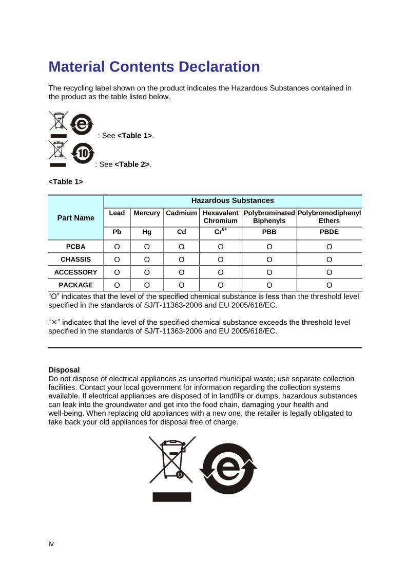
Material Contents Declaration The recycling label shown on the product indicates the Hazardous Substances contained in the product as the table listed below.
: See <Table 1>.
: See <Table 2>. <Table 1>
Part Name
Hazardous Substances
Lead Mercury Cadmium Hexavalent Chromium
Polybrominated Biphenyls
Polybromodiphenyl Ethers
Pb Hg Cd Cr6+
PBB PBDE
PCBA O O O O O O
CHASSIS O O O O O O
ACCESSORY O O O O O O
PACKAGE O O O O O O
“O” indicates that the level of the specified chemical substance is less than the threshold level specified in the standards of SJ/T-11363-2006 and EU 2005/618/EC. “” indicates that the level of the specified chemical substance exceeds the threshold level specified in the standards of SJ/T-11363-2006 and EU 2005/618/EC.
Disposal Do not dispose of electrical appliances as unsorted municipal waste; use separate collection facilities. Contact your local government for information regarding the collection systems available. If electrical appliances are disposed of in landfills or dumps, hazardous substances can leak into the groundwater and get into the food chain, damaging your health and well-being. When replacing old appliances with a new one, the retailer is legally obligated to take back your old appliances for disposal free of charge.
v
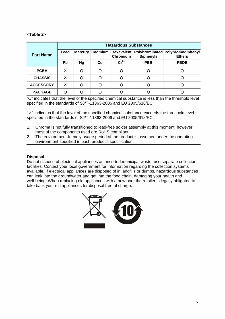
<Table 2>
Part Name
Hazardous Substances
Lead Mercury Cadmium Hexavalent Chromium
Polybrominated Biphenyls
Polybromodiphenyl Ethers
Pb Hg Cd Cr6+
PBB PBDE
PCBA O O O O O
CHASSIS O O O O O
ACCESSORY O O O O O
PACKAGE O O O O O O
“O” indicates that the level of the specified chemical substance is less than the threshold level specified in the standards of SJ/T-11363-2006 and EU 2005/618/EC. “” indicates that the level of the specified chemical substance exceeds the threshold level specified in the standards of SJ/T-11363-2006 and EU 2005/618/EC. 1. Chroma is not fully transitioned to lead-free solder assembly at this moment; however,
most of the components used are RoHS compliant. 2. The environment-friendly usage period of the product is assumed under the operating
environment specified in each product’s specification.
Disposal Do not dispose of electrical appliances as unsorted municipal waste; use separate collection facilities. Contact your local government for information regarding the collection systems available. If electrical appliances are disposed of in landfills or dumps, hazardous substances can leak into the groundwater and get into the food chain, damaging your health and well-being. When replacing old appliances with a new one, the retailer is legally obligated to take back your old appliances for disposal free of charge.
vi

vii
Safety Summary
The following general safety precautions must be observed during all phases of operation, service, and repair of this instrument. Failure to comply with these precautions or specific WARNINGS given elsewhere in this manual will violate safety standards of design, manufacture, and intended use of the instrument. Chroma assumes no liability for the customer’s failure to comply with these requirements.
BEFORE APPLYING POWER Verify that the power is set to match the rated input of this power supply.
PROTECTIVE GROUNDING Make sure to connect the protective grounding to prevent an electric shock before turning on the power.
NECESSITY OF PROTECTIVE GROUNDING Never cut off the internal or external protective grounding wire, or disconnect the wiring of protective grounding terminal. Doing so will cause a potential shock hazard that may bring injury to a person.
FUSES Only fuses with the required rated current, voltage, and specified type (normal blow, time delay, etc.) should be used. Do not use repaired fuses or short-circuited fuse holders. To do so could cause a shock or fire hazard.
DO NOT OPERATE IN AN EXPLOSIVE ATMOSPHERE Do not operate the instrument in the presence of flammable gases or fumes. The instrument should be used in an environment of good ventilation.
DO NOT REMOVE THE COVER OF THE INSTRUMENT Operating personnel must not remove the cover of the instrument. Component replacement and internal adjustment can be done only by qualified service personnel.
WARNING Touching the output terminal on the rear panel when the power or current is set and outputting may result in personal injury or death.
viii
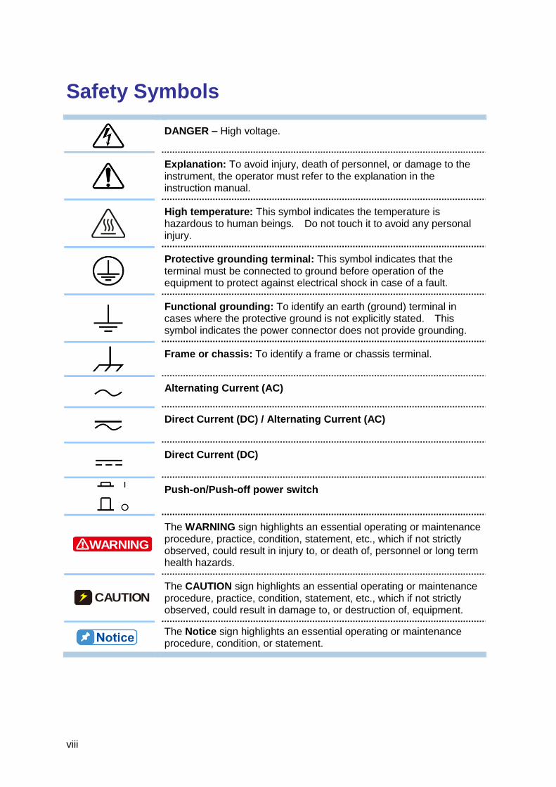
Safety Symbols
DANGER – High voltage.
Explanation: To avoid injury, death of personnel, or damage to the instrument, the operator must refer to the explanation in the instruction manual.
High temperature: This symbol indicates the temperature is hazardous to human beings. Do not touch it to avoid any personal injury.
Protective grounding terminal: This symbol indicates that the terminal must be connected to ground before operation of the equipment to protect against electrical shock in case of a fault.
Functional grounding: To identify an earth (ground) terminal in cases where the protective ground is not explicitly stated. This symbol indicates the power connector does not provide grounding.
Frame or chassis: To identify a frame or chassis terminal.
Alternating Current (AC)
Direct Current (DC) / Alternating Current (AC)
Direct Current (DC)
Push-on/Push-off power switch
WARNING
The WARNING sign highlights an essential operating or maintenance procedure, practice, condition, statement, etc., which if not strictly observed, could result in injury to, or death of, personnel or long term health hazards.
CAUTION The CAUTION sign highlights an essential operating or maintenance procedure, practice, condition, statement, etc., which if not strictly observed, could result in damage to, or destruction of, equipment.
The Notice sign highlights an essential operating or maintenance procedure, condition, or statement.

ix
Revision History The following lists the additions, deletions and modifications in this manual at each revision. Date Version Revised Sections May 2010 1.0 Complete this manual. Aug. 2010 1.1 Modify the following sections to add new model 62150H-1000S and
I-V Curve Programming function: – “Specifications” and “Other Specifications” as well as Notes in the
chapter of “Overview” – “Specification of Parallel Capacitance “ in the chapter of
“Installation” – “Setting Configuration “ and “SERIES/PARALLEL “ in the chapter
of “Manual Operation” Add the following: – Suggested O type terminal specification in the section of “Input
Connection” under “Installation” – “SAS Subsystem” in the chapter of “Remote Operation” Update the following: – “TABLE MODE” and “SAS MODE” section in the chapter of
“Manual Operation” – “IV Subsystem” in the chapter of “Remote Operation”
Apr. 2011 1.2 Add the following in the chapter of “Overview” & “Remote Operation”: – Specification of model 62050H-600S – Two reference figures in the “CAUTION” under Specification – TRIG command to “SAS Subsystem” Update the following in the chapter of “Overview”: – Specification of 62150H-1000S – The figure of front panel of 62000H with Solar Array Simulation
and main power switch Nov. 2011 1.3 Add A620028 and A620027 SLAVE models in the manual. Aug. 2012 1.4 Update the following:
Description in “Specification” section Value of minimum output voltage in “Other Specifications”section Notice in “Checking the Package” section Notice in “SERIES/PARALLEL” section Notice in “Assembling Series/Parallel Communication Interface”
section Add “D/D FAULT Protection” section in the chapter of “Manual Operation”
Oct. 2013 1.5 Add the following functions (only applicable when the firmware is upgraded to 2.00): − “CURR. SHARING ERR Protection”, “FPGA UPDATE!
Protection”, “C/S CABLE ERR. Protection”, “MATCH Warning”, “RS485 PARSER”, “EN50530 MODE” and “SANDIA_ MODE” sections in the chapter of “Manual Operation”
− “EN50530 MODE” and “SANDIA_ MODE” description in the section of “SAS Subsystem”
Jul. 2014 1.6 Add Model 62020H-150S along with its specifications and usage descriptions in the manual.
Mar. 2015 1.7 Update the following: The figure of rear panel. The output connecting cables diagram for Model 62020H-150S.


Programmable DC Power Supply (with Solar Array Simulation) 62000H Series Operating & Programming Manual
xi
Table of Contents 1. Overview ........................................................................................................... 1-1
1.1 Introduction ......................................................................................................... 1-1 1.2 System Functions ............................................................................................... 1-1
1.2.1 Operation Mode .......................................................................................... 1-1 1.2.2 Protection .................................................................................................... 1-1 1.2.3 Output/Indication ......................................................................................... 1-2 1.2.4 Input Control Signals ................................................................................... 1-2 1.2.5 Measuring & Editing .................................................................................... 1-2
1.3 Specifications ...................................................................................................... 1-2 1.3.1 Other Specifications .................................................................................... 1-4
1.4 Function Keys ................................................................................................... 1-10 1.4.1 Front Panel ............................................................................................... 1-10 1.4.2 Rear Panel ................................................................................................ 1-12
2. Installation ........................................................................................................ 2-1 2.1 Checking the Package ........................................................................................ 2-1
2.1.1 Maintenance & Cleaning ............................................................................. 2-2 2.2 Preparation for Use ............................................................................................. 2-2
2.2.1 Normal Environment Conditions .................................................................. 2-3 2.3 Requirements of Input Power .............................................................................. 2-3
2.3.1 Ratings ........................................................................................................ 2-3 2.3.2 Input Connection ......................................................................................... 2-3
2.4 Remote Sensing ................................................................................................. 2-6 2.4.1 Correct Connection ..................................................................................... 2-6 2.4.2 Reverse Connection of Remote Sensing Wire Polarity ................................ 2-7
2.5 Output Connection .............................................................................................. 2-7 2.5.1 Rear Panel Output....................................................................................... 2-7 2.5.2 Specification of Connecting Wire ............................................................... 2-10 2.5.3 Specification of Parallel Capacitance ........................................................ 2-10 2.5.4 Installing the Handle (62150H for example) ............................................... 2-11
2.6 Power On Procedure ........................................................................................ 2-11
3. Manual Operation ............................................................................................. 3-1 3.1 Introduction ......................................................................................................... 3-1 3.2 Setting Voltage & Current ................................................................................... 3-1 3.3 Setting Configuration .......................................................................................... 3-2
3.3.1 SYSTEM SETUP ........................................................................................ 3-5 3.3.1.1 APG ........................................................................................................ 3-5 3.3.1.2 BUZZER ................................................................................................ 3-10 3.3.1.3 POWER ON STATUS ........................................................................... 3-10
3.3.2 OUTPUT SETUP ...................................................................................... 3-12 3.3.2.1 VOLTAGE LIMIT SETTING ................................................................... 3-13 3.3.2.2 CURRENT LIMIT SETTING .................................................................. 3-14 3.3.2.3 VOLTAGE SLEW RATE ........................................................................ 3-15 3.3.2.4 CURRENT SLEW RATE SETTING ....................................................... 3-16 3.3.2.5 Setting DC_ON ...................................................................................... 3-17 3.3.2.6 Setting IV CURVE Parameters .............................................................. 3-18
3.3.3 SERIES/PARALLEL .................................................................................. 3-21 3.3.3.1 Connecting Series/Parallel Output Cable ............................................... 3-22 3.3.3.2 Assembling Series/Parallel Communication Interface ............................ 3-22 3.3.3.3 Setting Series/Parallel Operation Mode ................................................. 3-25 3.3.3.4 Setting Series Parameters ..................................................................... 3-31
Programmable DC Power Supply (with Solar Array Simulation) 62000H Series Operating & Programming Manual
xii
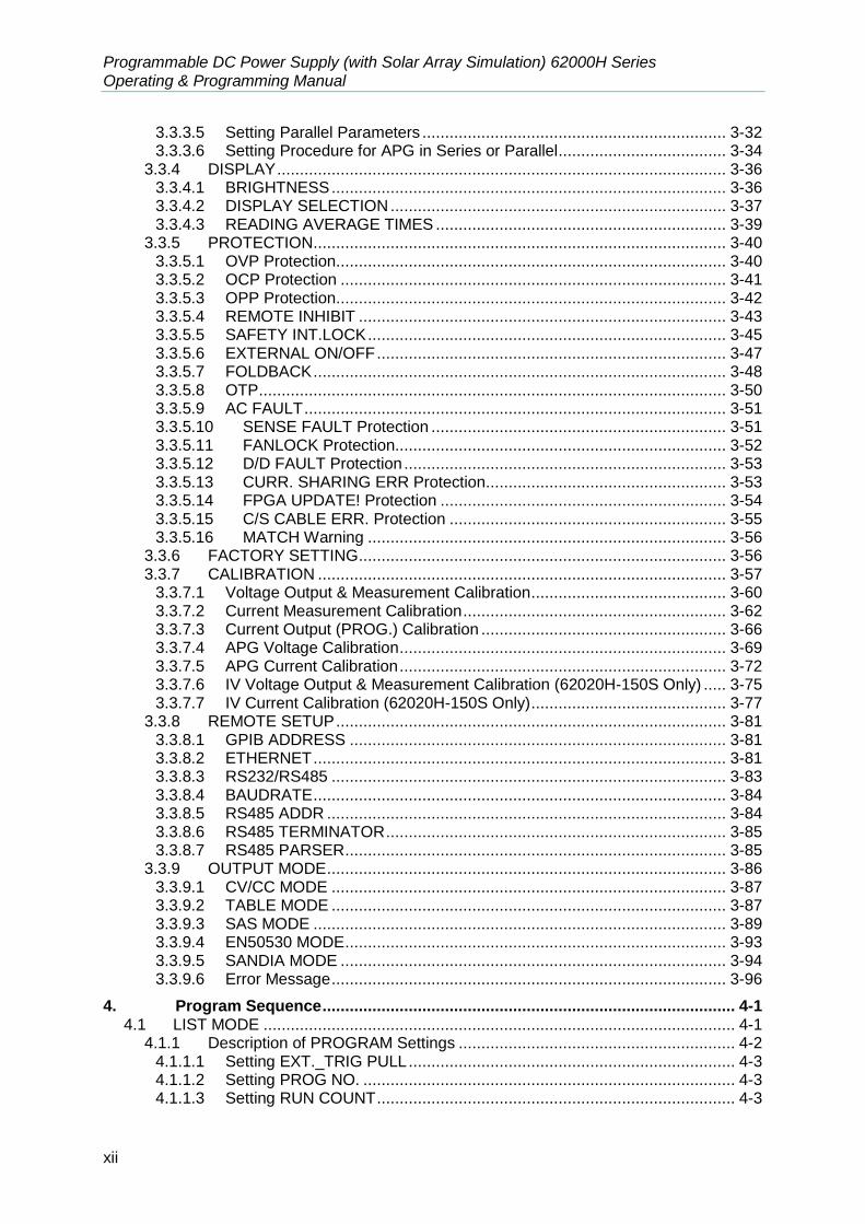
3.3.3.5 Setting Parallel Parameters ................................................................... 3-32 3.3.3.6 Setting Procedure for APG in Series or Parallel ..................................... 3-34
3.3.4 DISPLAY ................................................................................................... 3-36 3.3.4.1 BRIGHTNESS ....................................................................................... 3-36 3.3.4.2 DISPLAY SELECTION .......................................................................... 3-37 3.3.4.3 READING AVERAGE TIMES ................................................................ 3-39
3.3.5 PROTECTION ........................................................................................... 3-40 3.3.5.1 OVP Protection ...................................................................................... 3-40 3.3.5.2 OCP Protection ..................................................................................... 3-41 3.3.5.3 OPP Protection ...................................................................................... 3-42 3.3.5.4 REMOTE INHIBIT ................................................................................. 3-43 3.3.5.5 SAFETY INT.LOCK ............................................................................... 3-45 3.3.5.6 EXTERNAL ON/OFF ............................................................................. 3-47 3.3.5.7 FOLDBACK ........................................................................................... 3-48 3.3.5.8 OTP ....................................................................................................... 3-50 3.3.5.9 AC FAULT ............................................................................................. 3-51 3.3.5.10 SENSE FAULT Protection ................................................................. 3-51 3.3.5.11 FANLOCK Protection......................................................................... 3-52 3.3.5.12 D/D FAULT Protection ....................................................................... 3-53 3.3.5.13 CURR. SHARING ERR Protection..................................................... 3-53 3.3.5.14 FPGA UPDATE! Protection ............................................................... 3-54 3.3.5.15 C/S CABLE ERR. Protection ............................................................. 3-55 3.3.5.16 MATCH Warning ............................................................................... 3-56
3.3.6 FACTORY SETTING ................................................................................. 3-56 3.3.7 CALIBRATION .......................................................................................... 3-57
3.3.7.1 Voltage Output & Measurement Calibration ........................................... 3-60 3.3.7.2 Current Measurement Calibration .......................................................... 3-62 3.3.7.3 Current Output (PROG.) Calibration ...................................................... 3-66 3.3.7.4 APG Voltage Calibration ........................................................................ 3-69 3.3.7.5 APG Current Calibration ........................................................................ 3-72 3.3.7.6 IV Voltage Output & Measurement Calibration (62020H-150S Only) ..... 3-75 3.3.7.7 IV Current Calibration (62020H-150S Only) ........................................... 3-77
3.3.8 REMOTE SETUP ...................................................................................... 3-81 3.3.8.1 GPIB ADDRESS ................................................................................... 3-81 3.3.8.2 ETHERNET ........................................................................................... 3-81 3.3.8.3 RS232/RS485 ....................................................................................... 3-83 3.3.8.4 BAUDRATE ........................................................................................... 3-84 3.3.8.5 RS485 ADDR ........................................................................................ 3-84 3.3.8.6 RS485 TERMINATOR ........................................................................... 3-85 3.3.8.7 RS485 PARSER .................................................................................... 3-85
3.3.9 OUTPUT MODE ........................................................................................ 3-86 3.3.9.1 CV/CC MODE ....................................................................................... 3-87 3.3.9.2 TABLE MODE ....................................................................................... 3-87 3.3.9.3 SAS MODE ........................................................................................... 3-89 3.3.9.4 EN50530 MODE .................................................................................... 3-93 3.3.9.5 SANDIA MODE ..................................................................................... 3-94 3.3.9.6 Error Message ....................................................................................... 3-96
4. Program Sequence ........................................................................................... 4-1 4.1 LIST MODE ........................................................................................................ 4-1
4.1.1 Description of PROGRAM Settings ............................................................. 4-2 4.1.1.1 Setting EXT._TRIG PULL ........................................................................ 4-3 4.1.1.2 Setting PROG NO. .................................................................................. 4-3 4.1.1.3 Setting RUN COUNT ............................................................................... 4-3

Programmable DC Power Supply (with Solar Array Simulation) 62000H Series Operating & Programming Manual
xiii
4.1.1.4 Setting PROG CHAIN .............................................................................. 4-5 4.1.1.5 Setting CLEAR PROGRAM ..................................................................... 4-8
4.1.2 Setting Sequence ........................................................................................ 4-9 4.1.2.1 Setting Sequence Number..................................................................... 4-10 4.1.2.2 Setting Sequence Type ......................................................................... 4-10 4.1.2.3 Setting Time .......................................................................................... 4-14 4.1.2.4 Setting Voltage ...................................................................................... 4-14 4.1.2.5 Setting Voltage Slew Rate ..................................................................... 4-14 4.1.2.6 Setting Current ...................................................................................... 4-14 4.1.2.7 Setting Current Slew Rate ..................................................................... 4-15
4.1.3 Execution in LIST MODE........................................................................... 4-15 4.1.3.1 Running LIST MODE ............................................................................. 4-15 4.1.3.2 Program List Mode Description ............................................................. 4-16
4.2 V_STEP MODE ................................................................................................ 4-16 4.2.1 Setting V_STEP MODE ............................................................................. 4-17
4.2.1.1 Setting START_VOLTAGE .................................................................... 4-17 4.2.1.2 Setting END_VOLTAGE ........................................................................ 4-18 4.2.1.3 Setting RUN_TIME ................................................................................ 4-18
4.2.2 Execution of V_STEP MODE .................................................................... 4-19 4.2.2.1 Running V_STEP MODE ....................................................................... 4-19 4.2.2.2 Description of Program V_Step Mode ................................................... 4-20
4.3 IV PROGRAM ................................................................................................... 4-20 4.3.1 Setting IV-PROGRAM ............................................................................... 4-21 4.3.2 Setting IV-Sequence ................................................................................. 4-22
4.3.2.1 Setting Sequence Number..................................................................... 4-22 4.3.2.2 Setting IV-FILE Number ........................................................................ 4-23 4.3.2.3 Setting Sequence Type ......................................................................... 4-23 4.3.2.4 Setting Time .......................................................................................... 4-24
4.3.3 Execution of IV PROGRAM ....................................................................... 4-25 4.3.3.1 Running IV PROGRAM ......................................................................... 4-25 4.3.3.2 IV Program Main Screen ....................................................................... 4-26
5. Remote Operation ............................................................................................ 5-1 5.1 Overview ............................................................................................................. 5-1
5.1.1 USB Interface .............................................................................................. 5-1 5.1.2 Setting GPIB, Ethernet, RS-232C & RS-485 Parameters ............................ 5-1 5.1.3 Connecting RS-232C .................................................................................. 5-1 5.1.4 Connecting RS-485 ..................................................................................... 5-2 5.1.5 Ethernet Remote Control ............................................................................. 5-3
5.1.5.1 Selecting the LAN to be Connected ......................................................... 5-4 5.1.5.2 Setting IP, Subnet Mask & Gateway ........................................................ 5-6 5.1.5.3 Confirming Network Connected Successfully ........................................ 5-12 5.1.5.4 Communicating with the Instrument ....................................................... 5-13
5.2 GPIB Function of 62000H Series ...................................................................... 5-18 5.3 Introduction to Programming ............................................................................. 5-18
5.3.1 Conventions .............................................................................................. 5-19 5.3.2 Numerical Data Formats............................................................................ 5-19 5.3.3 Boolean Data Format ................................................................................ 5-19 5.3.4 Character Data Format .............................................................................. 5-19 5.3.5 Basic Definition ......................................................................................... 5-20
5.3.5.1 Command Tree Structure ...................................................................... 5-20 5.3.5.2 Program Headers .................................................................................. 5-20 5.3.5.3 Common Command and Query Headers ............................................... 5-20 5.3.5.4 Instrument-Controlled Headers .............................................................. 5-20
Programmable DC Power Supply (with Solar Array Simulation) 62000H Series Operating & Programming Manual
xiv
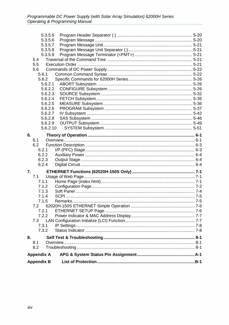
5.3.5.5 Program Header Separator (:) ............................................................... 5-20 5.3.5.6 Program Message ................................................................................. 5-20 5.3.5.7 Program Message Unit .......................................................................... 5-21 5.3.5.8 Program Message Unit Separator (;) ..................................................... 5-21 5.3.5.9 Program Message Terminator (<PMT>) ................................................ 5-21
5.4 Traversal of the Command Tree ....................................................................... 5-21 5.5 Execution Order ................................................................................................ 5-21 5.6 Commands of DC Power Supply ....................................................................... 5-22
5.6.1 Common Command Syntax ...................................................................... 5-22 5.6.2 Specific Commands for 62000H Series ..................................................... 5-26
5.6.2.1 ABORT Subsystem ............................................................................... 5-26 5.6.2.2 CONFIGURE Subsystem ...................................................................... 5-26 5.6.2.3 SOURCE Subsystem ............................................................................ 5-32 5.6.2.4 FETCH Subsystem ................................................................................ 5-35 5.6.2.5 MEASURE Subsystem .......................................................................... 5-36 5.6.2.6 PROGRAM Subsystem ......................................................................... 5-37 5.6.2.7 IV Subsystem ........................................................................................ 5-42 5.6.2.8 SAS Subsystem .................................................................................... 5-46 5.6.2.9 OUTPUT Subsystem ............................................................................. 5-49 5.6.2.10 SYSTEM Subsystem ......................................................................... 5-51
6. Theory of Operation ......................................................................................... 6-1 6.1 Overview ............................................................................................................. 6-1 6.2 Function Description ........................................................................................... 6-3
6.2.1 I/P (PFC) Stage ........................................................................................... 6-3 6.2.2 Auxiliary Power ........................................................................................... 6-4 6.2.3 Output Stage ............................................................................................... 6-4 6.2.4 Digital Circuit ............................................................................................... 6-4
7. ETHERNET Functions (62020H-150S Only) .................................................... 7-1 7.1 Usage of Web Page ............................................................................................ 7-1
7.1.1 Home Page (index.html) .............................................................................. 7-1 7.1.2 Configuration Page...................................................................................... 7-2 7.1.3 Soft Panel ................................................................................................... 7-4 7.1.4 SCPI ........................................................................................................... 7-5 7.1.5 Remarks ...................................................................................................... 7-5
7.2 62020H-150S ETHERNET Simple Operation ..................................................... 7-6 7.2.1 ETHERNET SETUP Page ........................................................................... 7-6 7.2.2 Power Indicator & MAC Address Display ..................................................... 7-7
7.3 LAN Configuration Initialize (LCI) Function .......................................................... 7-7 7.3.1 IP Settings ................................................................................................... 7-8 7.3.2 Status Indicator ........................................................................................... 7-8
8. Self Test & Troubleshooting ............................................................................ 8-1 8.1 Overview ............................................................................................................. 8-1 8.2 Troubleshooting .................................................................................................. 8-1
Appendix A APG & System Status Pin Assignment ................................................ A-1
Appendix B List of Protection ................................................................................. B-1

Overview
1-1
1. Overview
1.1 Introduction
Chroma 62000H Series with Solar Array Simulation are high power density DC Power Supplies that can provide stable DC output and accurate measurement for voltage and current. The features of 62000H Series with Solar Array Simulation DC Power Supply are: (1) The output is able to simulate the I-V curve of solar panel module with Programming
Mode provided. (2) Voltage mode with two loops control able to provide stable and quick responded
output, also to set the slew rate of output voltage and current. (3) High power density output the maximum output power can up to 15kW under 3U
height. (4) 16-bit ADC/16-bit DAC provides excellent resolution. (5) Lower transient spike and transient response time makes the unit under test gets the
most stable output and the best protection under the circumstance of load variation (6) Editing mode (Programming Mode) for output waveform provides multiple output
voltage and current combinations in real time for long period test. (7) Rotary knob and keyboard control on the front panel to set the output voltage and
current. (8) VFD panel gives users a high brightness and wide view angle interface for operation. (9) Via GPIB/Ethernet (option), USB, RS-232/RS-485 or APG (analog programmable
interface) interface to do remote control.
1.2 System Functions
1.2.1 Operation Mode
(1) Local operation is performed by the keyboard and rotary knob on the front panel. (2) Remote control is done via GPIB/Ethernet (option), USB or RS-232/RS-485 interface. (3) Through the APG input to control output via analog signal. (4) The settings and editions of I-V curve are done by Solar Array Simulation Soft Panel.
1.2.2 Protection
(1) Protections for voltage phase loss, input over-voltage or under-voltage, output over- voltage, over-current, over-power, over-temperature, fan fail, CV/CC foldback and etc. are available.
(2) Free temperature control for fan speed.

Programmable DC Power Supply (with Solar Array Simulation) 62000H Series Operating & Programming Manual
1-2
1.2.3 Output/Indication
(1) Auxiliary power output (12Vdc/10mA). (2) Analog monitors (V/I Monitor) the output signal instantaneously. This allows signals to
be easily monitored by external instruments (DMM, Oscilloscope, etc). Able to set the output level indication (DC ON) signal.
(3) Output indicator (DC ON) signal. (4) Protection state indication (OVP/OCP/OPP /FAN LOCK/AC FAULT, etc). (5) Over temperature (OTP) protection signal. (6) CV/CC status indicators. (7) Output status indicators.
1.2.4 Input Control Signals
(1) Remote sense input for voltage drop compensation. (2) Analog reference voltage (APG) input in which the setting of voltage and current can be
set by the voltage source, current source and resistance that adjusted for the panel setting.
(3) Remote inhibit control signal (TTL)
1.2.5 Measuring & Editing
(1) Measurement for voltage, current and power. (2) 10 programs and 100 sequences to edit voltage/current waveform output. (3) One run time voltage program that can be set for long hour. (4) 10 programs and 100 sequences to edit I-V curve waveform output.
1.3 Specifications
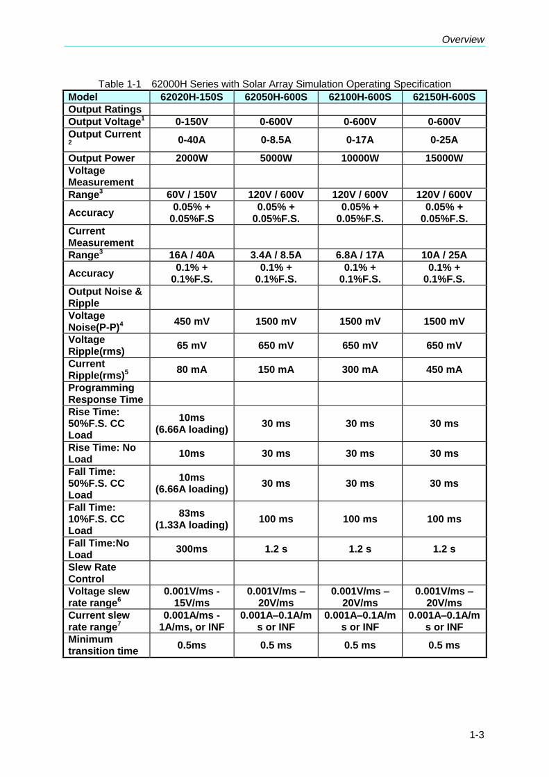
Chroma 62000H Series High Power Density DC Power Supplies with Solar Array Simulation contain 2KW (62020H), 5KW (62050H), 10KW (62100H) and 15KW (62150H) 4 sub-series by the output power and the power supply of each sub-series has various output specifications. Table 1-1 lists the output specifications of 62000H Series DC POWER SUPPLIES with Solar Array Simulation 2KW, 5KW, 10KW and 15KW. (It is suggested to warm up 10 minutes or more to begin the tests. The operation of DC Power Supply for output
voltage must be 5% larger than full-scale. The test condition is 25 5°C and under resistance load.)
Overview
1-3
Table 1-1 62000H Series with Solar Array Simulation Operating Specification
Model 62020H-150S 62050H-600S 62100H-600S 62150H-600S
Output Ratings
Output Voltage1 0-150V 0-600V 0-600V 0-600V
Output Current 2
0-40A 0-8.5A 0-17A 0-25A
Output Power 2000W 5000W 10000W 15000W
Voltage Measurement
Range3 60V / 150V 120V / 600V 120V / 600V 120V / 600V
Accuracy 0.05% +
0.05%F.S 0.05% +
0.05%F.S. 0.05% +
0.05%F.S. 0.05% +
0.05%F.S.
Current Measurement
Range3 16A / 40A 3.4A / 8.5A 6.8A / 17A 10A / 25A
Accuracy 0.1% +
0.1%F.S. 0.1% +
0.1%F.S. 0.1% +
0.1%F.S. 0.1% +
0.1%F.S.
Output Noise & Ripple
Voltage Noise(P-P)4
450 mV 1500 mV 1500 mV 1500 mV
Voltage Ripple(rms)
65 mV 650 mV 650 mV 650 mV
Current Ripple(rms)5
80 mA 150 mA 300 mA 450 mA
Programming Response Time
Rise Time: 50%F.S. CC Load
10ms (6.66A loading)
30 ms 30 ms 30 ms
Rise Time: No Load
10ms 30 ms 30 ms 30 ms
Fall Time: 50%F.S. CC Load
10ms (6.66A loading)
30 ms 30 ms 30 ms
Fall Time: 10%F.S. CC Load
83ms (1.33A loading)
100 ms 100 ms 100 ms
Fall Time:No Load
300ms 1.2 s 1.2 s 1.2 s
Slew Rate Control
Voltage slew rate range6
0.001V/ms - 15V/ms
0.001V/ms – 20V/ms
0.001V/ms – 20V/ms
0.001V/ms – 20V/ms
Current slew rate range7
0.001A/ms - 1A/ms, or INF
0.001A–0.1A/ms or INF
0.001A–0.1A/ms or INF
0.001A–0.1A/ms or INF
Minimum transition time
0.5ms 0.5 ms 0.5 ms 0.5 ms
Programmable DC Power Supply (with Solar Array Simulation) 62000H Series Operating & Programming Manual
1-4
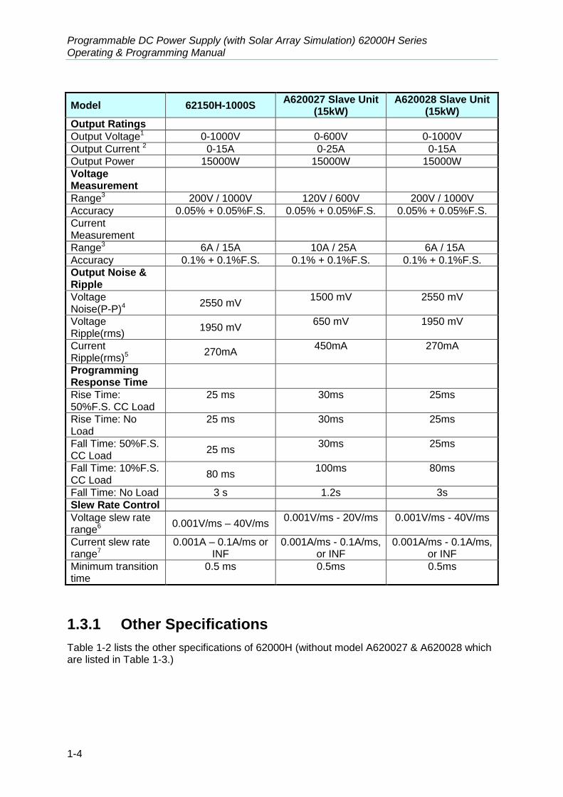
Model 62150H-1000S A620027 Slave Unit
(15kW) A620028 Slave Unit
(15kW)
Output Ratings
Output Voltage1 0-1000V 0-600V 0-1000V
Output Current 2 0-15A 0-25A 0-15A
Output Power 15000W 15000W 15000W
Voltage Measurement
Range3 200V / 1000V 120V / 600V 200V / 1000V
Accuracy 0.05% + 0.05%F.S. 0.05% + 0.05%F.S. 0.05% + 0.05%F.S.
Current Measurement
Range3 6A / 15A 10A / 25A 6A / 15A
Accuracy 0.1% + 0.1%F.S. 0.1% + 0.1%F.S. 0.1% + 0.1%F.S.
Output Noise & Ripple
Voltage Noise(P-P)4
2550 mV 1500 mV 2550 mV
Voltage Ripple(rms)
1950 mV 650 mV 1950 mV
Current Ripple(rms)5
270mA 450mA 270mA
Programming Response Time
Rise Time: 50%F.S. CC Load
25 ms 30ms 25ms
Rise Time: No Load
25 ms 30ms 25ms
Fall Time: 50%F.S. CC Load
25 ms 30ms 25ms
Fall Time: 10%F.S. CC Load
80 ms 100ms 80ms
Fall Time: No Load 3 s 1.2s 3s
Slew Rate Control
Voltage slew rate range6
0.001V/ms – 40V/ms 0.001V/ms - 20V/ms 0.001V/ms - 40V/ms
Current slew rate range7
0.001A – 0.1A/ms or INF
0.001A/ms - 0.1A/ms, or INF
0.001A/ms - 0.1A/ms, or INF
Minimum transition time
0.5 ms 0.5ms 0.5ms
1.3.1 Other Specifications
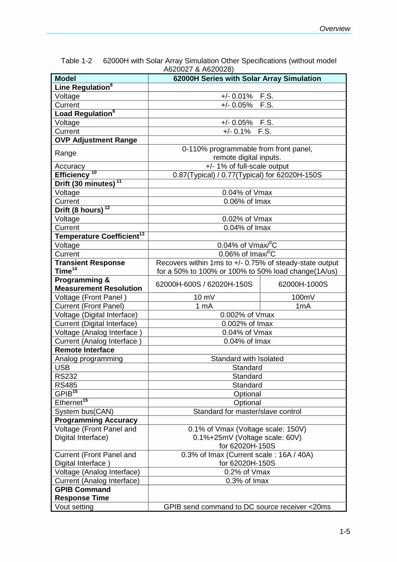
Table 1-2 lists the other specifications of 62000H (without model A620027 & A620028 which are listed in Table 1-3.)
Overview
1-5
Table 1-2 62000H with Solar Array Simulation Other Specifications (without model A620027 & A620028)
Model 62000H Series with Solar Array Simulation
Line Regulation8
Voltage +/- 0.01% F.S.
Current +/- 0.05% F.S.
Load Regulation9
Voltage +/- 0.05% F.S.
Current +/- 0.1% F.S.
OVP Adjustment Range
Range 0-110% programmable from front panel,
remote digital inputs.
Accuracy +/- 1% of full-scale output
Efficiency 10 0.87(Typical) / 0.77(Typical) for 62020H-150S
Drift (30 minutes) 11
Voltage 0.04% of Vmax
Current 0.06% of Imax
Drift (8 hours) 12
Voltage 0.02% of Vmax
Current 0.04% of Imax
Temperature Coefficient13
Voltage 0.04% of Vmax/0C
Current 0.06% of Imax/0C
Transient Response Time14
Recovers within 1ms to +/- 0.75% of steady-state output for a 50% to 100% or 100% to 50% load change(1A/us)
Programming & Measurement Resolution
62000H-600S / 62020H-150S 62000H-1000S
Voltage (Front Panel ) 10 mV 100mV
Current (Front Panel) 1 mA 1mA
Voltage (Digital Interface) 0.002% of Vmax
Current (Digital Interface) 0.002% of Imax
Voltage (Analog Interface ) 0.04% of Vmax
Current (Analog Interface ) 0.04% of Imax
Remote Interface
Analog programming Standard with Isolated
USB Standard
RS232 Standard
RS485 Standard
GPIB15 Optional
Ethernet15 Optional
System bus(CAN) Standard for master/slave control
Programming Accuracy
Voltage (Front Panel and Digital Interface)
0.1% of Vmax (Voltage scale: 150V) 0.1%+25mV (Voltage scale: 60V)
for 62020H-150S
Current (Front Panel and Digital Interface )
0.3% of Imax (Current scale : 16A / 40A) for 62020H-150S
Voltage (Analog Interface) 0.2% of Vmax
Current (Analog Interface) 0.3% of Imax
GPIB Command Response Time
Vout setting GPIB send command to DC source receiver <20ms

Programmable DC Power Supply (with Solar Array Simulation) 62000H Series Operating & Programming Manual
1-6
?Volt, ? Current Under GPIB command using Measure <25ms
Analog Interface (I/O)
Voltage and Current Programming inputs (I/P)
0-10Vdc / 0-5Vdc / 0-5k ohm / 4-20 mA of F.S.
Voltage and Current monitor output (O/P)
0-10Vdc / 0-5Vdc / 4-20mA of F.S.
External ON/OFF (I/P) TTL: Active Low or High (Selective)
DC_ON Signal (O/P) Level by user define
( Time delay= 1ms at voltage slew rate of 10V/ms.)
CV or CC mode Indicator (O/P)
TTL Level High=CV mode; TTL Level Low=CC mode
OTP Indicator (O/P) TTL: Active Low
System Fault indicator (O/P)
TTL: Active Low
Auxiliary power supply (O/P)
Nominal supply voltage : 12Vdc / Maximum current sink capability: 10mA
Safety interlock (I/P) Time accuracy: <100ms
Remote inhibit (I/P) TTL: Active Low
Analog Interface Accuracy
Measurement
Voltage 0.5% of F.S.
Current 0.75% of F.S.
Series & Parallel Operation16
Master / Slave control via CAN for 10 units up to 150KW. (Series: two units / Parallel: ten units )
Master / Slave control via CAN for 10 units up to 20KW. (Series: two units / Parallel: ten units)
for 62020H-150S
Auto Sequencing (List mode)
Number of program 10
Number of sequence 100
Dwell time Range 5ms – 15,000s
Trig. Source Manual / Auto / External
Auto Sequencing (Step mode)
Start voltage 0 to Full scale
End voltage 0 to Full scale
Run time hh : mm : ss.ss ( 00 : 00 : 00.01 to 99 : 59 : 59.99 )
Trig. Source Auto
Auto Sequencing (I-V program)
Number of program 10
Number of sequence 100
Dwell time Range 1s – 15,000s
Trig. Source Manual / Auto
Input Specification
AC input voltage 3phase , 3 wire + ground17
200/220 Vac (operating range 180 -242 Vac) 380/400 Vac (operating range 342 - 440 Vac) 440/480 Vac (operating range 396 - 528 Vac)
AC input voltage Single Phase
200/240VAC +/- 10% for 62020H-150S

Overview
1-7
AC frequency range 47-63 Hz
Power factor
62020H: 0.95 (200/240Vac)
62050H: 0.5
(200/220Vac)
(380/400Vac)
(440/480Vac)
62100H: 0.55
(200/220Vac)
(380/400Vac)
(440/480Vac)
62150H : 0.6
(200/220Vac)
(380/400Vac)
(440/480Vac)
General Specification
Maximum Remote Sense Line Drop Compensation
2% of full scale voltage per line (4% total)
Weight
62020H : Approx. 17 kg / 37.44 lbs 62050H : Approx. 23 kg / 50.70 lbs 62100H : Approx. 29 kg / 63.88 lbs 62150H : Approx. 35 kg / 77.09 lbs
Dimensions (HxWxD) mm18
132.8 x 428 x 610 mm / 5.23 x 16.85 x 24.02 inch
89 mm x 428 mm x 465 mm / 3.5 x 16.85 x 16.73 inch for 62020H-150S
Operating Temperature Rage
0°C ~ 40°C
Storage Temperature Rage -40°C ~ +85°C
Approval CE
Table 1-3 A620027/A620028 Slave Other Specifications
Model A620027/A620028 Slave Unit (15kW)
Line Regulation8
Voltage +/- 0.01% F.S.
Current +/- 0.05% F.S.
Load Regulation9
Voltage +/- 0.05% F.S.
Current +/- 0.1% F.S.
OVP Adjustment Range
Range 0-110% programmable from front panel,
remote digital inputs
Accuracy +/- 1% of full-scale output
Efficiency 10 0.87(Typical)
Drift (30 minutes) 11
Voltage 0.04% of Vmax
Current 0.06% of Imax
Drift (8 hours) 12
Voltage 0.02% of Vmax
Current 0.04% of Imax
Temperature Coefficient13
Voltage 0.04% of Vmax/0C
Current 0.06% of Imax/0C
Transient Response Time14
Recovers within 1ms to +/- 0.75% of steady-state output for a 50% to 100% or 100% to 50% load change(1A/us)
Remote Interface

Programmable DC Power Supply (with Solar Array Simulation) 62000H Series Operating & Programming Manual
1-8
System bus (CAN) Standard
Input Specification
AC input voltage 3phase , 3 wire + ground17
200/220 Vac (operating range 180 -242 Vac) 380/400 Vac (operating range 342 - 440 Vac) 440/480 Vac (operating range 396 - 528 Vac) *
*Call for Availability
AC frequency range 47-63 Hz
Power factor 0.6 (200/220Vac) 0.6 (380/400Vac) 0.6 (440/480Vac)
General Specification
Maximum Remote Sense Line Drop Compensation
2% of full scale voltage per line (4% total)
Weight < 35 kg / 77.16 lbs.
Dimensions (HxWxD) mm18 132.8 x 428 x 610 mm / 5.23 x 16.85 x 24.02 inch
Operating Temperature Rage
0°C ~ 40°C
Storage Temperature Rage -40°C ~ +85°C
Approval CE
All specifications are subject to change without prior notice.
Note 1. Minimum output voltage <0.5% of rate voltage. The 62020H-150S minimum
output rated voltage is 1.5V. 2. Minimum output current <0.2% of rate current. 3. The Range applicable for change only valid in CV/CC MODE and the Range
of TABLE MODE and SAS MODE is Full Scale. 4. The measurement frequency range is 20k Hz ~ 20M Hz. 5. The output voltage range is from 10% to 100% and the output current is
measured under the condition of full load. 6. This setting is only valid when there is output and the voltage as well as the
current setting is larger than the one specified in Note 1 and the load current is 40% over Imax. When the output is connected to capacitor, the voltage slew rate will decrease if the capacitance is increased.
7. This setting is valid only when the load voltage is larger than the one specified in Note 1. The factory default is INF. Be sure to adjust the slew rate settings as required.
8. 10% variation under rated voltage. 9. For 0-100% load step with nominal line voltage. 10. Under the maximum output power condition of rated voltage. 11. The maximum drift of output power during 30 minutes test period when the
input, loading and ambient temperature are fixed. 12. The maximum drift of output power after warmed up for 30 minutes and 8
hours test period when the input, loading and ambient temperature are fixed. 13. The change caused by the ambient temperature per centigrade when the
input and loading are fixed. 14. Over 50% of maximum output voltage and the loading slew rate is 1A/us for
rise and fall. 15. Either Ethernet or GPIB can be selected when shipping. 16. Please consult with the manufacturer when there are 5 DC Power Supplies
are connected in parallel. There is parallel mode for DC Power Supply when the I-V Curve function is enabled.
17. Varied by local voltage regulation, all models of 5KW, 10kW & 15kW in the 62000H Series with Solar Array Simulation have 200/220 Vac, 380/400 Vac

Overview
1-9
and 440/480 Vac 3 types of input voltage for selection. There is also a single phase power supply 200/240 Vac, 2KW model available for selection. The user can follow the local voltage regulation to select a proper voltage spec. The Power Supply is set with the required input voltage when shipped and when the input voltage is not within the range, it will show AC_fault protection and shut down the output.
18. It is the chassis size without any accessories.
CAUTION 1. If it is applied to battery charge or inductance load such as motors,
the output port needs to connect a diode in series to prevent the load current from backwash and damage the device interior, see Figure 1-1.
2. For switchable power load applications, if the output load cable is longer (>20cm) it is suggested to strand the load cable and parallel the capacitance at the load power input to prevent any unexpected oscillation from occurring, see Figure 1-2.
3. For load application, it can parallel connect the capacitor more than 100uF to the load input to avoid any unexpected oscillation from occurring
4. Do not bond the external input, output cable and communication cable all together to avoid interference and cause device error.
Figure 1-1
Figure 1-2
WARNING Voltage from the two output terminals to earth varies with the 62000H Series Models with Solar Array Simulation as Table 1-4 shows below:
Table 1-4
Model Max. Voltage (Vdc) Difference
between Output Terminal and Earth

Programmable DC Power Supply (with Solar Array Simulation) 62000H Series Operating & Programming Manual
1-10
62020H-150S ±250
62050H-600S ±1200
62100H-600S ±1200
62150H-600S ±1200
62150H-1000S ±1200
A620028 ±1200
A620027 ±1200
If the voltage exceeds the above range it may result damage to the DC Power Supply.
1.4 Function Keys
1.4.1 Front Panel
Figure 1-3 Front Panel of 62000H with Solar Array Simulation
Figure 1-4 Front Panel of Slave Model A620027/A620028

Overview
1-11
Figure 1-5 Front Panel of 62020H-150S with Solar Array Simulation
Table 1-5 Description of Front Panel
Item Symbol Description
1
Display: VFD Display: it shows the output settings and measured result.
2 0 to
9 and
●
Numeric and Decimal Point: Users can use the numeric keys and the decimal point key to enter digital data.
3 VOLT
Voltage Setting Key: Enters voltage setting mode. Users can use numeric
keys or voltage rotary knob (
) to input voltage values
4 CURR
Current Setting Key: Enters current limit setting mode. Users can use
numeric keys or current rotary knob (
) to input current limit values.
5 PROG
PROGRAM Key: Press this key to skip to “Program Function Page” for setting waveform editing mode.
6 LOCAL
LOCAL Key: Press this key to switch the control mode from remote control back to manual operating mode.
7 ENTER
ENTER Key: Press this key to confirm the parameter settings.
8 DEL
Delete Key: Press this key to delete the input value.
9 EXIT
EXIT Key: Press this key to go to previous screen. If this key is
pressed before “SAVE
” is pressed, the screen will go back to “MAIN PAGE” and the data will not be saved.
10 LOCK
LOCK Key: Press this key to lock all keys and rotary knob.
To unlock press “LOCK
” for 3 seconds to release it.
11 ON/OFF
ON/OFF Key: Press this key to control the output to “ON” or “OFF”.
12 CONF
CONFIG Key: Press this key to skip to “Config Choose Page” for setting various functions.
13 SAVE
SAVE Key: Press this key to save the settings in “Program and Config

Programmable DC Power Supply (with Solar Array Simulation) 62000H Series Operating & Programming Manual
1-12
Item Symbol Description
Function Page”.
14
Cursor Movement Keys:
Use “ ” and “ ” keys to move the cursor to the parameter to be modified.
15
Voltage Rotary Knob:
The user can turn the knob “
” to input data or select an item.
16
Current Rotary Knob:
The user can turn the knob “
” to input data or select an item.
17
Main Power Switch: It switches the power on or off.
18
Rack Bracket:(Option) Use the left (right) bracket to fix the Power Supply on the Rack.
19
LED on Slave Model: When the slave model is on, the LED varies with its status. The green light indicates POWER ON, the yellow light indicates the data is transmitting or communication is normal while the red light indicates fault occurred during operation.
1.4.2 Rear Panel
Figure 1-6 Rear Panel of 62000H with Solar Array Simulation
Overview
1-13
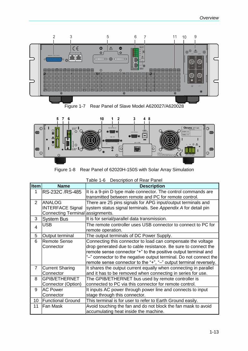
Figure 1-7 Rear Panel of Slave Model A620027/A620028
Figure 1-8 Rear Panel of 62020H-150S with Solar Array Simulation
Table 1-6 Description of Rear Panel
Item Name Description
1 RS-232C /RS-485 It is a 9-pin D type male connector. The control commands are transmitted between remote and PC for remote control.
2 ANALOG INTERFACE Signal Connecting Terminal
There are 25 pins signals for APG input/output terminals and system status signal terminals. See Appendix A for detail pin assignments.
3 System Bus It is for serial/parallel data transmission. 4
USB The remote controller uses USB connector to connect to PC for remote operation.
5 Output terminal The output terminals of DC Power Supply.
6 Remote Sense Connector
Connecting this connector to load can compensate the voltage drop generated due to cable resistance. Be sure to connect the remote sense connector “+” to the positive output terminal and “–” connector to the negative output terminal. Do not connect the remote sense connector to the “+”, “–” output terminal reversely.
7 Current Sharing Connector
It shares the output current equally when connecting in parallel and it has to be removed when connecting in series for use.
8 GPIB/ETHERNET Connector (Option)
The GPIB/ETHERNET bus used by remote controller is connected to PC via this connector for remote control.
9 AC Power Connector
It inputs AC power through power line and connects to input stage through this connector.
10 Functional Ground This terminal is for user to refer to Earth Ground easily.
11 Fan Mask Avoid touching the fan and do not block the fan mask to avoid accumulating heat inside the machine.

Programmable DC Power Supply (with Solar Array Simulation) 62000H Series Operating & Programming Manual
1-14
The callout 8 in Figure 1-6 is the cover plate for standard configuration. When GPIB/ETHERNET interface is selected as shipping default, it will be installed before shipment as Figure 1-9 (a) & (b) shows.
(a) GPIB Interface (b) ETHERNET Interface
Figure 1-9
Installation
2-1
2. Installation
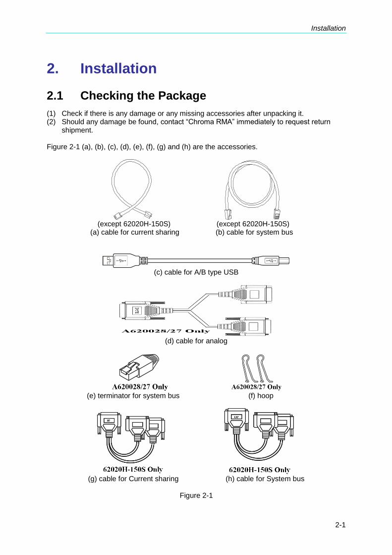
2.1 Checking the Package
(1) Check if there is any damage or any missing accessories after unpacking it. (2) Should any damage be found, contact “Chroma RMA” immediately to request return
shipment. Figure 2-1 (a), (b), (c), (d), (e), (f), (g) and (h) are the accessories.
(except 62020H-150S) (except 62020H-150S)
(a) cable for current sharing (b) cable for system bus
(c) cable for A/B type USB
(d) cable for analog
(e) terminator for system bus (f) hoop
(g) cable for Current sharing (h) cable for System bus
Figure 2-1
Programmable DC Power Supply (with Solar Array Simulation) 62000H Series Operating & Programming Manual
2-2
1. Please keep all of the packing materials in case the device has to
be returned for repair. 2. Do not return the instrument to the factory without obtaining prior
RMA acceptance from Chroma. 3. Check if the accessories listed in the packing list are all received.
CAUTION The power supply is too heavy for one person to safely lift and mount. To avoid injury, ask a co-worker for assistance.
2.1.1 Maintenance & Cleaning
Remove all connected wires and cables from the instrument before cleaning. Use a brush to clean the dust on it and if there are stains on the chassis that cannot be removed by brush, wipe it with volatile liquid (such as Cleaning Naphtha). Do not use any corrosive liquid to avoid damaging the chassis. Use a damp cloth with soap water or soft detergent to clean the LCD front panel. For internal cleaning, use a low-pressure air gun for the dust inside or send it back to our agent for cleaning.
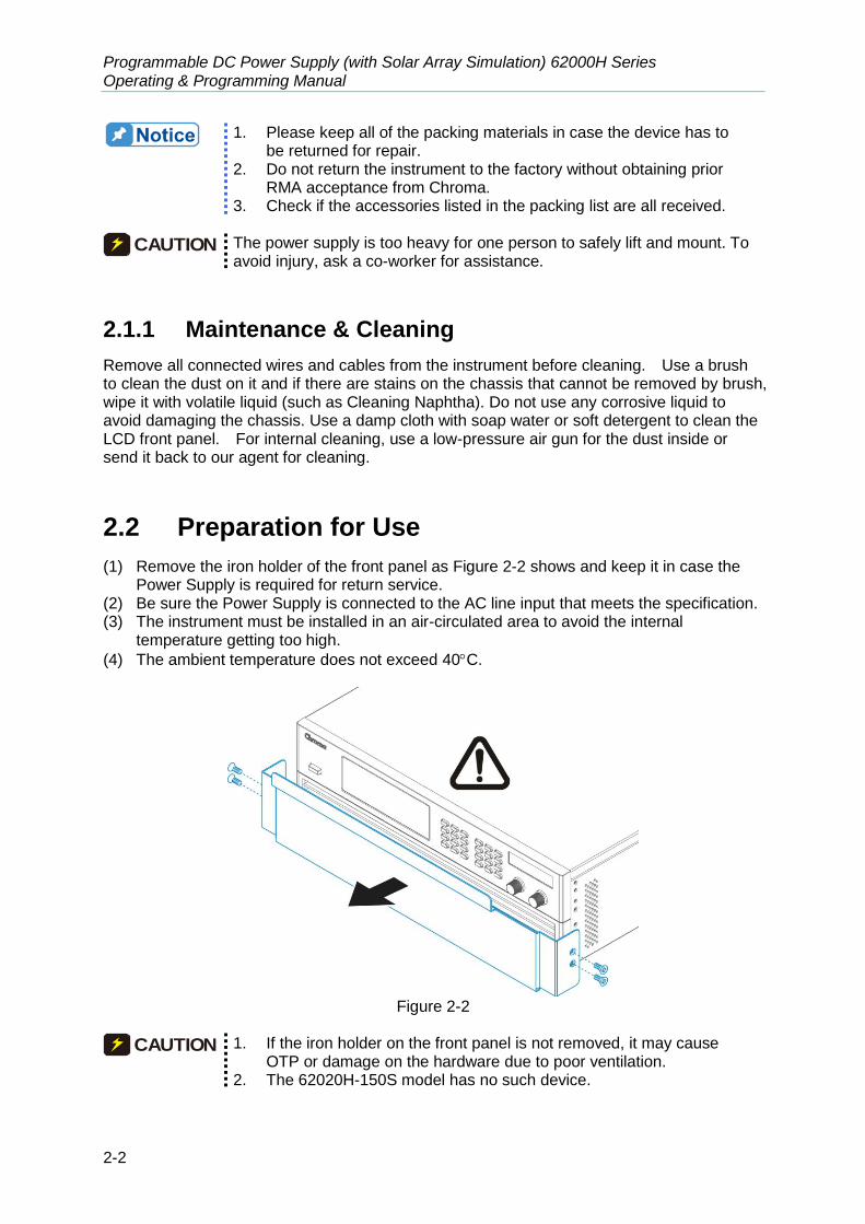
2.2 Preparation for Use
(1) Remove the iron holder of the front panel as Figure 2-2 shows and keep it in case the Power Supply is required for return service.
(2) Be sure the Power Supply is connected to the AC line input that meets the specification. (3) The instrument must be installed in an air-circulated area to avoid the internal
temperature getting too high.
(4) The ambient temperature does not exceed 40C.
Figure 2-2
CAUTION 1. If the iron holder on the front panel is not removed, it may cause
OTP or damage on the hardware due to poor ventilation. 2. The 62020H-150S model has no such device.

Installation
2-3
2.2.1 Normal Environment Conditions
(1) In door use. (2) Altitude up to 2000 meters.
(3) Temperature 0C to 40C.
(4) Maximum relative humidity is 65% at 25C and increasing linearly to 90% relative
humidity for temperature up to 40C. (5) Input AC power voltage fluctuations can be up to 10% of the rated voltage. (6) Transient over voltage is impulse withstand CAT II. (7) Pollution degree II.
2.3 Requirements of Input Power
2.3.1 Ratings
(1) Model 62050H-xxxxS Maximum input power: 12 kVA
(2) Model 62100H-xxxxS Maximum input power: 21 kVA
(3) Model 62150H-xxxxS/A620027/A620028 Maximum input power: 29 kVA
(4) Model 62020H-150S: Maximum input power: 2.9 kVA
Vin
62050H-xxxxS 62100H-xxxxS 62150H-xxxxS A620027 A620028
62020H-150S
200/220 39A 69 A 93 A Current of each phase
380/400 22A 37 A 50 A
440/480 19A 32 A 44 A
200/240 15.2 A
2.3.2 Input Connection
(1) The input connector board is located at the right of the rear panel. (2) The power line must be 85°C rated at least. (3) The power cable width must be within 6AWG~8AWG. (Note: 10AWG~12AWG is
required for Model 62020H-150S.) (4) See Figure 2-3 (a), (b) to assemble 62000H and Figure 2-5 to assemble Model
62020H-150S. Execute the following steps: a. Remove the input terminal safety cover from the rear panel of DC Power Supply. b. Scrape off the skin of power cable tip (the bare portion is about 1cm) and use an O
type terminal to crimp it. (For Model 62020H-150S, the bare portion needs to be tinned.)
c. Secure the power cable and input terminal with a Phillips screwdriver. The suggest range for lock torque is 30~40 (kg-cm). (For Model 62020H-150S, insert the power terminal and use a Phillips screwdriver to secure it.)
d. Lock the safety cover to avoid electric shock.
Model
Programmable DC Power Supply (with Solar Array Simulation) 62000H Series Operating & Programming Manual
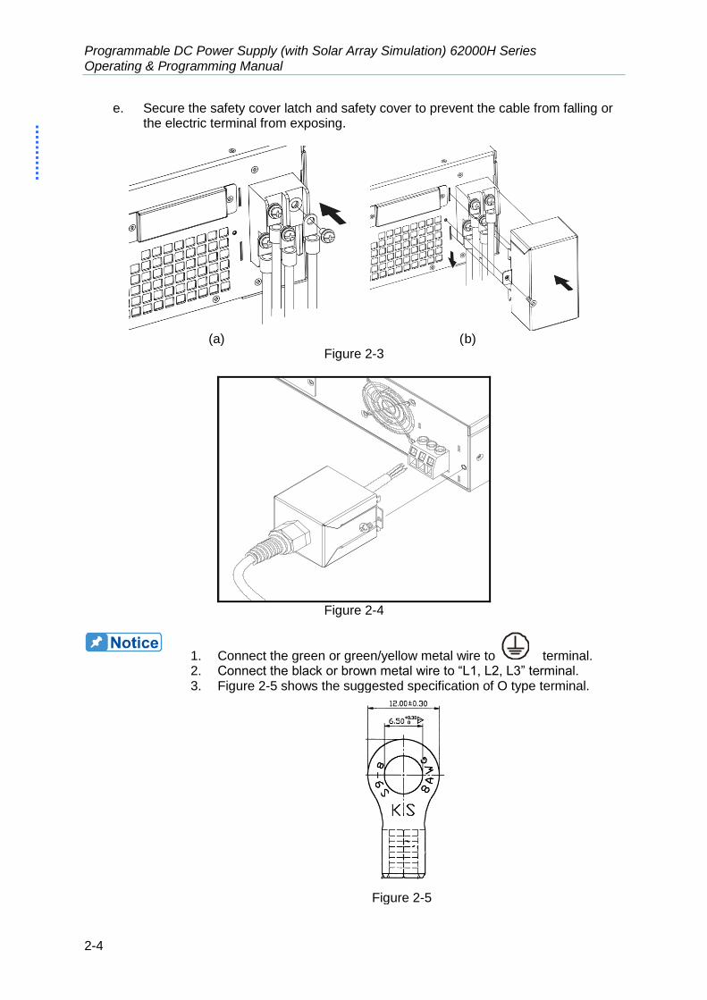
2-4
e. Secure the safety cover latch and safety cover to prevent the cable from falling or the electric terminal from exposing.
(a) (b)
Figure 2-3
Figure 2-4
1. Connect the green or green/yellow metal wire to terminal. 2. Connect the black or brown metal wire to “L1, L2, L3” terminal. 3. Figure 2-5 shows the suggested specification of O type terminal.
Figure 2-5

Installation
2-5
4. Connect the white or blue metal wire of Model 62020H-150S to the “N” terminal.
5. Connect the black or brown metal wire of Model 62020H-150S to the “L” terminal.
WARNING 1. To protect the operators, the wire connected to the GND terminal
( ) must be connected to the earth. Under no circumstances shall this DC Power Supply be operated without an adequate ground connection.
2. Installation of the power cord must be done by a professional and compliant with local electrical codes.
CAUTION 1. Be sure to select an appropriate withstand voltage cable based on
the varied input voltage. 2. To ensure the safe operation, follow the input power source during
installation to select the current rated BREAKER that closes to each phase and connect it to the input terminal in series.
Table 2-1 is the cable specification of PVC (105°C) with the ambient temperature at 30°C for reference.
Table 2-1 PVC (105°C) Cable Specification
Conductor Area
Sectional Area mm2
Safe Current (A)
Copper Conductor
Lead Conductor
1.25 15 --
2.0 20 --
3.5 30 --
5.5 40 --
8.0 55 --
14 70 50
22 90 70
30 120 90
38 145 100
50 175 120
80 230 150
100 260 200
125 300 240
150 350 270
200 425 330
250 500 380
325 600 450
400 700 500
500 800 600

Programmable DC Power Supply (with Solar Array Simulation) 62000H Series Operating & Programming Manual
2-6
2.4 Remote Sensing
2.4.1 Correct Connection
1. Connecting remote sensing wire correctly can ensure the output voltage is the set voltage. The DC Power Supply is able to compensate maximum 4% of F.S. line voltage drop.
2. Figure 2-6 shows the correct connection. Use two wires to connect the positive/negative connector of load to the remote sensing connector on the rear panel. The connecting wire diameter must be larger than 30AWG and its withstand voltage should be within the specification.
3. Though remote sensing is able to compensate the voltage drop; however, if the line loss is too large (see specification) it will cause protection on remote sensing as Figure 2-8 shows and is unable to compensate voltage drop correctly.
4. Connect the remote sensing wire of Model 62020H-150S as shown in Figure 2-7. 5. The Remote sensing wire needs to be connected to the DC Power Supply local output
or the remote input of UUT.
Figure 2-6
Figure 2-7

Installation
2-7
V = 6 0. 0 0 V I = 1 0. 0 0 _ A O F F
0 . 0 0 0 0 V 0 . 0 0 0 0 A S E N S E F A U L T 0 . 0 W
S H U T – D N
Figure 2-8
2.4.2 Reverse Connection of Remote Sensing Wire
Polarity
The polarity of remote sensing wire must be connected correctly, that is the “+” terminal is connected to the “+” of output terminal or to the connecting wire of the terminal, while the “–” terminal is connected to the “–” of output terminal or to the connecting wire of the terminal. If the polarity is connected reversely, the output will drop to 0V and prompt an error message “SENSE FAULT” as Figure 2-8 shows.
The DC Power Supply does not burn down due to reverse connection of polarity. Do the following step to reset it: 1. First power it off. 2. Connect the remote sensing wire properly. 3. Restart the DC Power Supply.
CAUTION 1. When there is voltage existed on the device output, please avoid
connecting Remote sense to the device output or UUT reversely as it may cause the hardware to blow up.
2. The voltage of Remote sensing and local output should be less than 10% V_MAX to prevent the device from blowing up.
3. If the Remote sense wire fell off, it could cause output voltage to overshoot. Be sure to install the Remote sense wire correctly to the DC Power Supply local output or the load UUT side before operating the device.
2.5 Output Connection
The output connector of 62000H Series DC Power Supply with Solar Array Simulation is located at the upper middle area on the rear panel and for Model 62020H-150S it is on the left side of rear panel. The load is connected to “+” and “–” output terminal.
2.5.1 Rear Panel Output
(1) The output terminal is located at the upper middle area on the rear panel. (For Model 62020H-150S, the output terminal is located on the left side of rear panel.)

Programmable DC Power Supply (with Solar Array Simulation) 62000H Series Operating & Programming Manual
2-8
(2) The output cable must be rated 85C at least. (3) Assembly see Figure 2-9 (a) & (b) and Figure 2-11 (c), (d), (e), (f) and (g) for
62020H-150S. Execute the steps below: a. Scrape off the skin of power cable tip (the bare portion is about 1cm) and use an O
type terminal to crimp it. b. Secure the power cable and input terminal with a Phillips screwdriver. c. Secure the safety cover latch and safety cover to prevent the cable from falling or
the electric terminal from exposing. (4) A standard hoop is attached when purchasing the A620028 or A620027 SLAVE model
to fix the current sharing cables as shown in Figure 2-10. Mount it first and then continue the installation as shown in Figure 2-9.
(a) (b)
Figure 2-9
Figure 2-10

Installation
2-9
(c) (d)
(e) (f)
(g)
Figure 2-11
CAUTION 1. To meet the safety requirement, the safety cover must be tightly
secured. 2. The diameter of the wire connected to load must be able to carry
the maximum current applied. 3. It is no need to use the 62020H-150S 9PIN current sharing cable
when using the device as a standalone.
WARNING For safety reason, do not exceed rated current (different from 62000H Series) for the output current to avoid any danger.
Programmable DC Power Supply (with Solar Array Simulation) 62000H Series Operating & Programming Manual
2-10
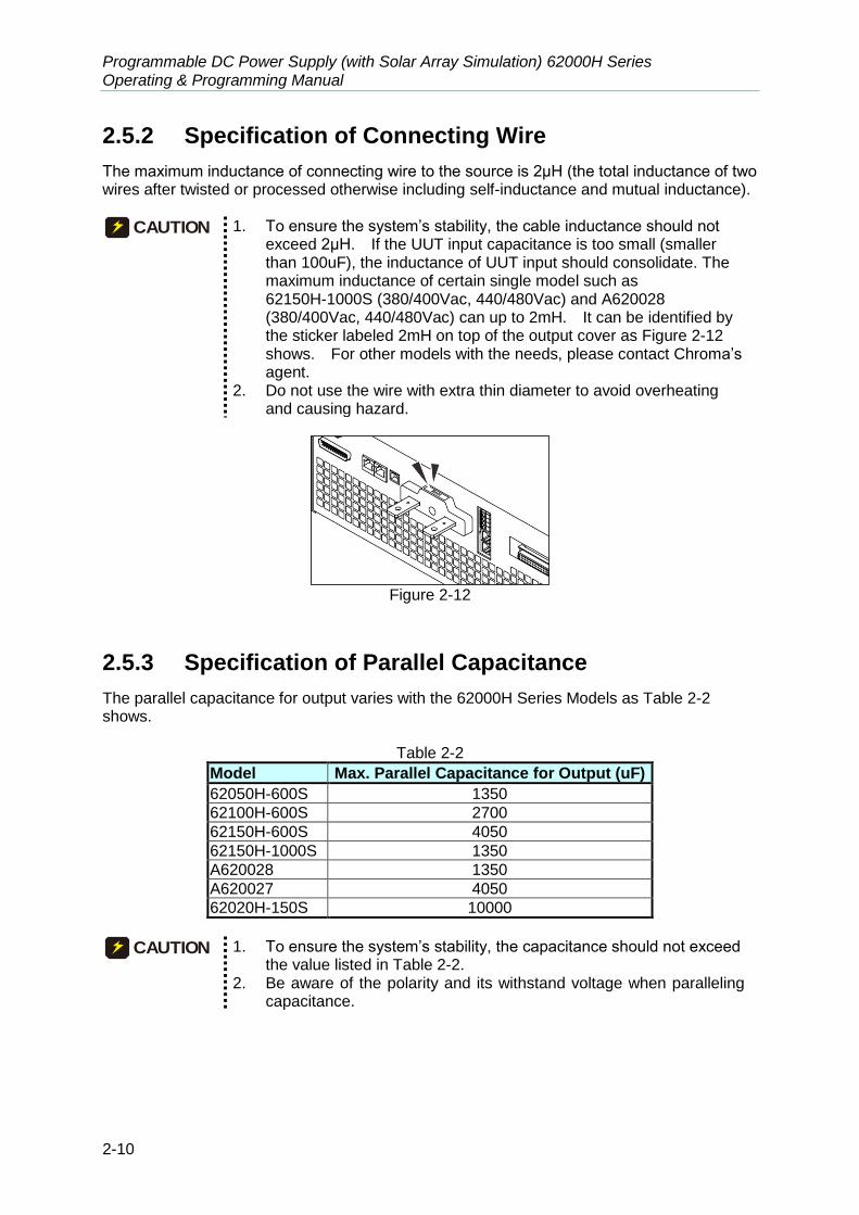
2.5.2 Specification of Connecting Wire
The maximum inductance of connecting wire to the source is 2μH (the total inductance of two wires after twisted or processed otherwise including self-inductance and mutual inductance).
CAUTION 1. To ensure the system’s stability, the cable inductance should not
exceed 2μH. If the UUT input capacitance is too small (smaller than 100uF), the inductance of UUT input should consolidate. The maximum inductance of certain single model such as 62150H-1000S (380/400Vac, 440/480Vac) and A620028 (380/400Vac, 440/480Vac) can up to 2mH. It can be identified by the sticker labeled 2mH on top of the output cover as Figure 2-12 shows. For other models with the needs, please contact Chroma’s agent.
2. Do not use the wire with extra thin diameter to avoid overheating and causing hazard.
Figure 2-12
2.5.3 Specification of Parallel Capacitance
The parallel capacitance for output varies with the 62000H Series Models as Table 2-2 shows.
Table 2-2
Model Max. Parallel Capacitance for Output (uF)
62050H-600S 1350
62100H-600S 2700
62150H-600S 4050
62150H-1000S 1350
A620028 1350
A620027 4050
62020H-150S 10000
CAUTION 1. To ensure the system’s stability, the capacitance should not exceed
the value listed in Table 2-2. 2. Be aware of the polarity and its withstand voltage when paralleling
capacitance.

Installation
2-11
2.5.4 Installing the Handle (62150H for example)
Use M4X12 flat head screws to secure the handle to the rack mounting kit as shown in Figure 2-13.
Figure 2-13 Installing the Handle
2.6 Power On Procedure
Plug in the power cord and turn on the power switch on front panel. The DC Power Supply will run a series of self-tests. The VFD on the front panel will light up and show as below:
S E L F T E S T . . .
Figure 2-14
Meanwhile, the DC Power Supply will run self-tests for memory, data and communication. Once the routine of self-tests are done, the model no. and serial no. will show on the screen and prompt “OK” at the right of the test item if passed. When self-test is done the display shows as below:

Programmable DC Power Supply (with Solar Array Simulation) 62000H Series Operating & Programming Manual
2-12
M O D E L : 6 2 1 5 0 H – 6 0 0 S S E R I A L N O :1
D I S P L A Y < O K >
F I R M W A R Y 0 0 . 0 7, D E C 1 7 2 0 0 9
F P G A 0 0 . 0 0 B
W A I T . . .
Figure 2-15
When the self tests of memory, data and communication are done, the screen turns to the MAIN PAGE automatically as shown below:
V = 0. 0 0_ V I = 0. 0 0 A O F F
0 . 0 0 0 0 V 0 . 0 0 0 0 A 0 . 0 W
Figure 2-16
WARNING The DC Power Supply internal circuit may not be able to reset if it is powered off and on immediately. It is suggested to wait for 3 seconds after powered off and power it on again.
CAUTION Before turning on the instrument, all protective grounding terminals, extension cord and devices must connect to earth. The hazard of potential electric shock may occur in any interrupted grounding and could injure personnel.

Manual Operation
3-1
3. Manual Operation
3.1 Introduction
The DC Power Supply can be operated manually or remotely via GPIB/ETHERNET (option) or USB or RS-232/RS-485 or APG interface which is described in Chapter 5 and section 3.3.1.1. The manual operation for using the front panel keyboard or rotary knobs to input the data is described in this chapter.
If the operation mode is not saved before the user powers the instrument off, the operation mode is manual (default) when power it on next time.
3.2 Setting Voltage & Current
There are two ways to set the output voltage (CV MODE) as Figure 3-1 shows: Method 1:
1. Press “ VOLT ”, the cursor for V on MAIN PAGE blinks.
2. Use the numeric keys ( 1 ~ 9 ) to set the value and press “ENTER
” to complete
the voltage setting or turn the “Rotary” (
) knob to adjust the set value.
3. Press “ ON/OFF ” to output the set voltage. (Please note that in order to remain in CV mode the current setting must be larger than the load current, otherwise the output voltage will not be equal to the set voltage.)
Method 2:
1. Press “ VOLT ”, the cursor for V on MAIN PAGE blinks.
2. When using the Rotary knob (
) for setting, the “ ”, “ ” keys can be used to move the cursor to each individual digit, and then turn the rotary knob to increase or decrease the unit of the set value.
3. Press “ ON/OFF ” to output the set voltage. (Please note that in order to remain in CV mode the current setting must be larger than the load current, otherwise the output voltage will not be equal to the set voltage.)
V = 0. 0 0_ V I = 0. 0 0 A O F F
0 . 0 0 0 0 V 0 . 0 0 0 0 A 0 . 0 W
Figure 3-1
Programmable DC Power Supply (with Solar Array Simulation) 62000H Series Operating & Programming Manual
3-2
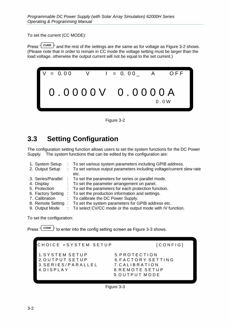
To set the current (CC MODE):
Press “ CURR ” and the rest of the settings are the same as for voltage as Figure 3-2 shows. (Please note that in order to remain in CC mode the voltage setting must be larger than the load voltage, otherwise the output current will not be equal to the set current.)
V = 0. 0 0 V I = 0. 0 0 _ A O F F
0 . 0 0 0 0 V 0 . 0 0 0 0 A 0 . 0 W
Figure 3-2
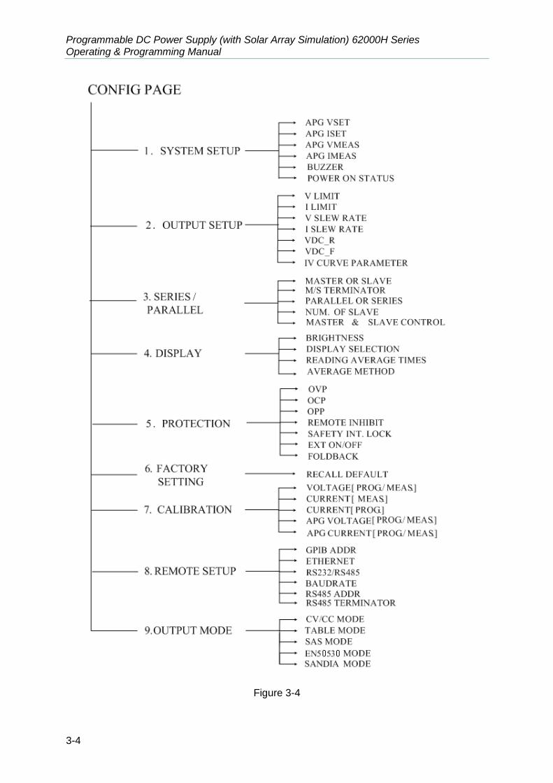
3.3 Setting Configuration
The configuration setting function allows users to set the system functions for the DC Power Supply. The system functions that can be edited by the configuration are: 1. System Setup : To set various system parameters including GPIB address. 2. Output Setup : To set various output parameters including voltage/current slew rate
etc. 3. Series/Parallel : To set the parameters for series or parallel mode. 4. Display : To set the parameter arrangement on panel. 5. Protection : To set the parameters for each protection function. 6. Factory Setting : To set the production information and settings. 7. Calibration : To calibrate the DC Power Supply. 8. Remote Setting : To set the system parameters for GPIB address etc. 9. Output Mode : To select CV/CC mode or the output mode with IV function.
To set the configuration:
Press “ CONF ” to enter into the config setting screen as Figure 3-3 shows.
C H O I C E = S Y S T E M S E T U P [ C O N F I G ]
1. S Y S T E M S E T U P 5. P R O T E C T I O N
2. O U T P U T S E T U P 6. F A C T O R Y S E T T I N G
3. S E R I E S / P A R A L L E L 7. C A L I B R A T I O N
4. D I S P L A Y 8. R E M O T E S E T U P
9. O U T P U T M O D E
Figure 3-3

Manual Operation
3-3
1. Use the numeric keys ( 1 ~ 9 ) or “Rotary” (
) knob to select the item to be set. 2. Press “ ENTER ” to confirm. 3. Press “ EXIT ” to return to the MAIN PAGE.
1. To cancel the setting, press “ EXIT ” to return to the MAIN PAGE.
2. Press “ VOLT ” or “ CURR ” in any page to return to the MAIN PAGE. Figure 3-4 shows the tree structure of CONFIG PAGE.
Programmable DC Power Supply (with Solar Array Simulation) 62000H Series Operating & Programming Manual
3-4
Figure 3-4
Manual Operation
3-5
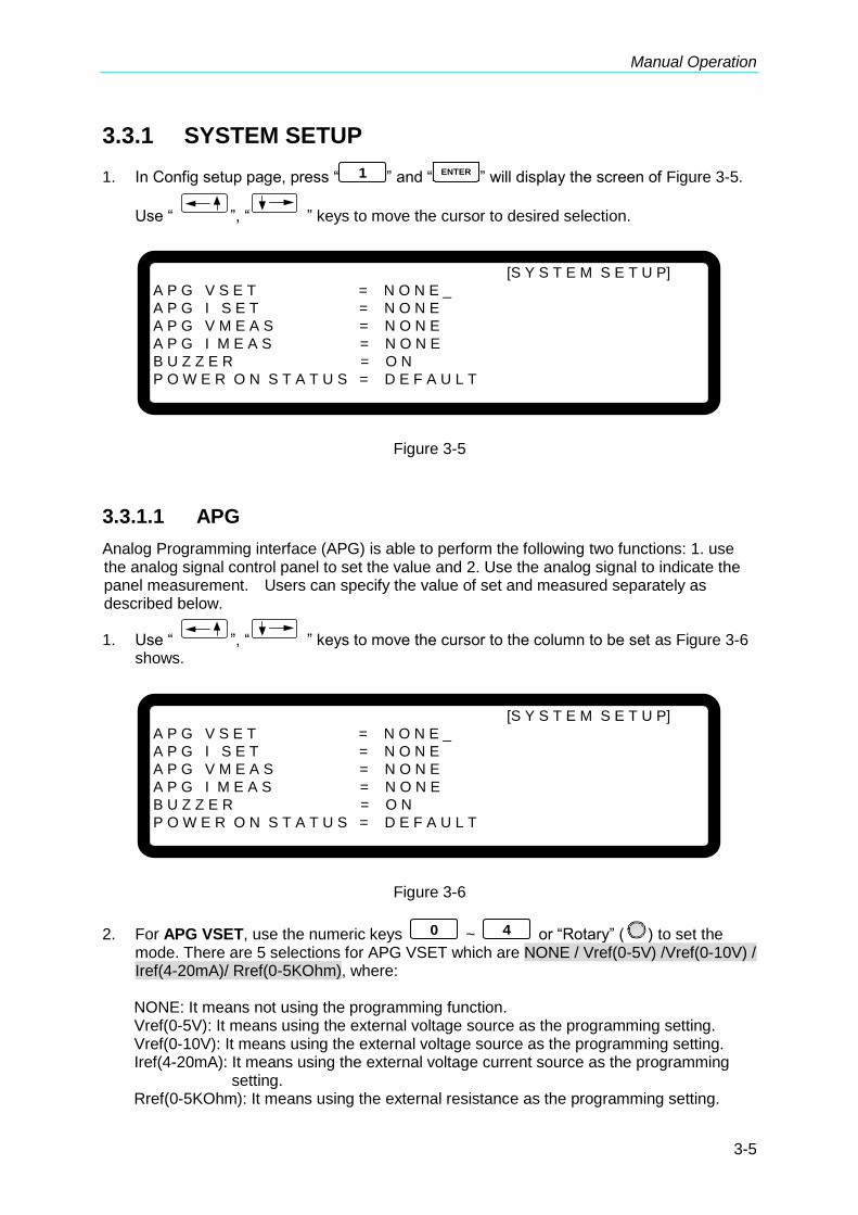
3.3.1 SYSTEM SETUP
1. In Config setup page, press “ 1 ” and “ENTER
” will display the screen of Figure 3-5.
Use “ ”, “ ” keys to move the cursor to desired selection.
[S Y S T E M S E T U P]
A P G V S E T = N O N E _
A P G I S E T = N O N E
A P G V M E A S = N O N E
A P G I M E A S = N O N E
B U Z Z E R = O N
P O W E R O N S T A T U S = D E F A U L T
Figure 3-5
3.3.1.1 APG
Analog Programming interface (APG) is able to perform the following two functions: 1. use the analog signal control panel to set the value and 2. Use the analog signal to indicate the panel measurement. Users can specify the value of set and measured separately as described below.
1. Use “ ”, “ ” keys to move the cursor to the column to be set as Figure 3-6 shows.
[S Y S T E M S E T U P]
A P G V S E T = N O N E _
A P G I S E T = N O N E
A P G V M E A S = N O N E
A P G I M E A S = N O N E
B U Z Z E R = O N
P O W E R O N S T A T U S = D E F A U L T
Figure 3-6
2. For APG VSET, use the numeric keys 0 ~ 4 or “Rotary” (
) to set the mode. There are 5 selections for APG VSET which are NONE / Vref(0-5V) /Vref(0-10V) / Iref(4-20mA)/ Rref(0-5KOhm), where:
NONE: It means not using the programming function.
Vref(0-5V): It means using the external voltage source as the programming setting. Vref(0-10V): It means using the external voltage source as the programming setting. Iref(4-20mA): It means using the external voltage current source as the programming
setting. Rref(0-5KOhm): It means using the external resistance as the programming setting.

Programmable DC Power Supply (with Solar Array Simulation) 62000H Series Operating & Programming Manual
3-6
3. Press “ENTER
” to confirm.
4. For APG ISET, use the numeric keys 0 ~ 4 or “Rotary” (
) to set the mode. There are 5 selections for APG ISET which are NONE / Vref(0-5V) / Vref(0-10V) / Iref(4-20mA) / Rref(0-5KOhm), where:
NONE: It means not using the programming function.
Vref (0-5V): It means using the external voltage source as the programming setting. Vref (0-10V): It means using the external voltage source as the programming setting. Iref (4-20mA): It means using the external voltage current source as the programming
setting. Rref(0-5KOhm): It means using the external resistance as the programming setting.
5. Press “ ENTER ” to confirm. 6. For APG VMEAS, use the numeric keys 0 ~ 3 or “Rotary” (
) to set the
mode. There are 4 selections for APG VMEAS which are NONE / Vref(0-5V) / Vref(0-10V) / Iref(4-20mA), where:
NONE: It means not using the measurement function.
Vref (0-5V): It means using the power supply output voltage source as the measurement result.
Vref (0-10V): It means using the power supply output voltage source as the measurement result.
Iref (4-20mA): It means using the power supply output current source as the measurement result.
7. Press “ ENTER ” to confirm. 8. For APG IMEAS, use the numeric keys 0 ~ 3 or “Rotary” (
) to set the
mode. There are 4 selections for APG IMEAS which are NONE / Vref(0-5V) / Vref(0-10V) / Iref(4-20mA), where: NONE: It means not using the measurement function.
Vref (0-5V): It means using the power supply output voltage source as the measurement result.
Vref (0-10V): It means using the power supply output voltage source as the measurement result.
Iref (4-20mA): It means using the power supply output current source as the
9. Press “ ENTER ” to confirm. 10. Press “ EXIT ” to return to the MAIN PAGE.
1. APG VSET/APG ISET has 5 selections which are NONE / Vref(0-5V) /
Vref(0-10V) / Iref(4-20mA)/ Rref(0-5KOhm), where: a. When selecting Vref=5V it means the DC Power Supply’s output
0V ~ 600V/0A ~ 25A will map to 0~5V as Figure 3-7(a) shows. b. When selecting Vref=10V it means the DC Power Supply’s output

Manual Operation
3-7
0V ~ 600V/0A ~ 25A will map to 0~10V as Figure 3-7 (b) shows. c. When selecting Iref=4-20mA it means the DC Power Supply’s
output 0V ~ 600V/0A ~ 25A will map to 4-20mA as Figure 3-7 (c) shows.
d. When selecting Vref=5KOhm it means the DC Power Supply’s output 0V ~ 600V/0A ~ 25A will map to 0~5KOhm as Figure 3-7 (d) shows.
D
C S
OU
RC
E S
ET
600V/25A
APG INPUT 5VD
C S
OU
RC
E S
ET
APG INPUT 10V
600V/25A
(a) (b)
DC
SO
UR
CE
SE
T
600V/25A
APG INPUT 4 ~ 20mA
DC
SO
UR
CE
SE
T
APG INPUT 5KOhm
600V/25A
(c) (d) Figure 3-7
2. APG VMEAS/APG IMEAS has 4 selections which are NONE /
Vref(0-5V) / Vref(0-10V) / Iref(4-20mA) where: a. When selecting Vref=5V it means the DC Power Supply’s
measurement output 0 ~ 600V/0A ~ 25A will map to 0~5V as Figure 3-8 (a) shows.
b. When selecting Vref=10V it means the DC Power Supply’s measurement output 0 ~ 600V/0A ~ 25A will map to 0~10V as Figure 3-8 (b) shows.
c. When selecting Iref=4~20mA it means the DC Power Supply’s measurement output 0 ~ 600V/0A ~ 25A will map to 4mA~20mA as Figure 3-8 (c) shows.
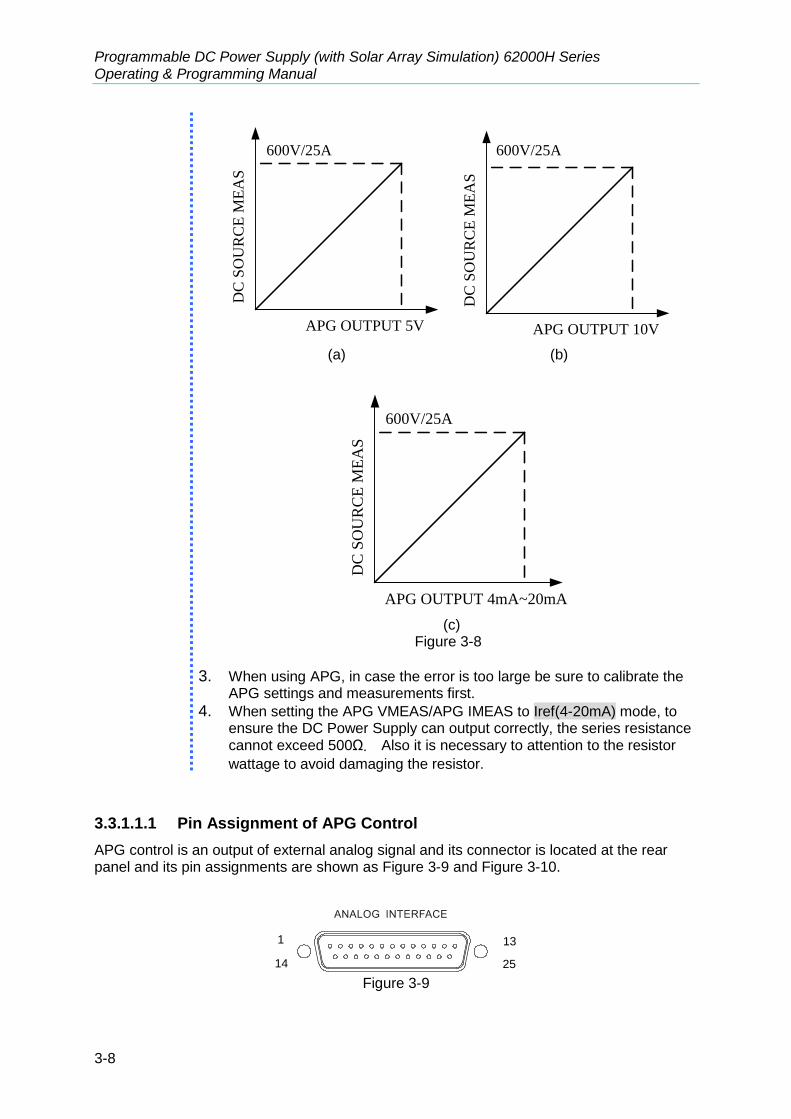
Programmable DC Power Supply (with Solar Array Simulation) 62000H Series Operating & Programming Manual
3-8
DC
SO
UR
CE
ME
AS
600V/25A
APG OUTPUT 5V
DC
SO
UR
CE
ME
AS
APG OUTPUT 10V
600V/25A
(a) (b)
D
C S
OU
RC
E M
EA
S
APG OUTPUT 4mA~20mA
600V/25A
(c)
Figure 3-8
3. When using APG, in case the error is too large be sure to calibrate the APG settings and measurements first.
4. When setting the APG VMEAS/APG IMEAS to Iref(4-20mA) mode, to ensure the DC Power Supply can output correctly, the series resistance cannot exceed 500Ω. Also it is necessary to attention to the resistor
wattage to avoid damaging the resistor.
3.3.1.1.1 Pin Assignment of APG Control
APG control is an output of external analog signal and its connector is located at the rear panel and its pin assignments are shown as Figure 3-9 and Figure 3-10.
1
14
13
25 Figure 3-9

Manual Operation
3-9
5 18 6 19
1
+12VAPI API GND AVO_SET_R AIO_SET_R AVO_SET_C AIO_SET_C AVO_SET_V AIO_SET_V
AVO_MEAS_C AIO_MEAS_C AVO_MEAS_V AIO_MEAS_V
14 2 15 3 16 4 17
- +
- +
sensing
sensing
sensing
sensing
Figure 3-10 Following lists the definition of each pin:
1. Auxiliary power Vcc: This pin outputs a +12Vdc power with maximum output current 10mA (output port).
2. Voltage programming: It inputs the resistance (0-5K Ohm) from this pin and APIGND that can control the output voltage (CV mode) linearly.
3. Voltage programming: It inputs the analog current (4-20mA) from this pin to APIGND that can control the output voltage (CV mode) linearly.
4. Voltage programming: It inputs the analog voltage (0-10Vdc or 0-5Vdc) from this pin to APIGND that can control the output voltage (CV mode) linearly.
5. Voltage measurement: This pin will output the voltage in analog signal 4mA-20mA for users to monitor it.
6. Voltage measurement: This pin will output the voltage in analog signal 0-5V or 0-10V for users to monitor it.
14. APIGND: This contact is the reference potential of APG interface. The potential is separated for APG and chassis, and the maximum tolerance of voltage differential is 70Vdc.
15. Current programming: It inputs the resistance (0-5K Ohm) from this pin and APIGND that can control the output current (CC mode) linearly.
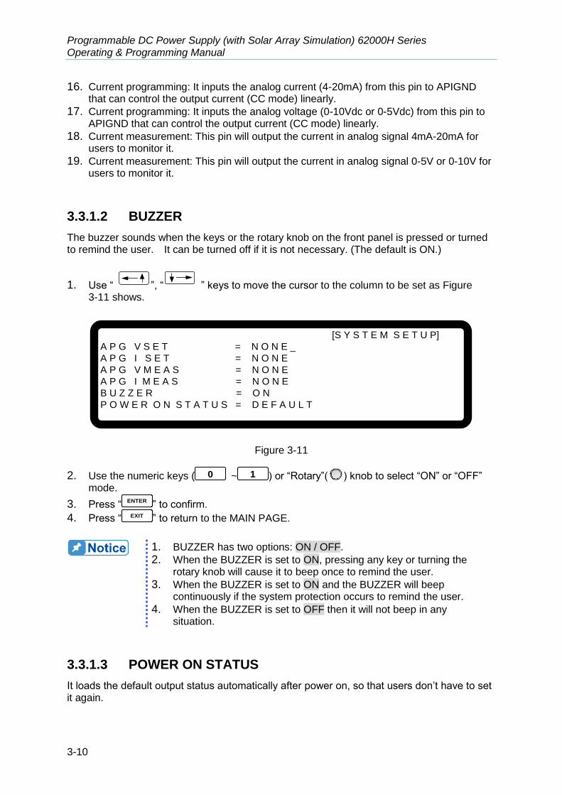
Programmable DC Power Supply (with Solar Array Simulation) 62000H Series Operating & Programming Manual
3-10
16. Current programming: It inputs the analog current (4-20mA) from this pin to APIGND that can control the output current (CC mode) linearly.
17. Current programming: It inputs the analog voltage (0-10Vdc or 0-5Vdc) from this pin to APIGND that can control the output current (CC mode) linearly.
18. Current measurement: This pin will output the current in analog signal 4mA-20mA for users to monitor it.
19. Current measurement: This pin will output the current in analog signal 0-5V or 0-10V for users to monitor it.
3.3.1.2 BUZZER
The buzzer sounds when the keys or the rotary knob on the front panel is pressed or turned to remind the user. It can be turned off if it is not necessary. (The default is ON.)
1. Use “ ”, “ ” keys to move the cursor to the column to be set as Figure 3-11 shows.
[S Y S T E M S E T U P]
A P G V S E T = N O N E _
A P G I S E T = N O N E
A P G V M E A S = N O N E
A P G I M E A S = N O N E
B U Z Z E R = O N
P O W E R O N S T A T U S = D E F A U L T
Figure 3-11
2. Use the numeric keys ( 0 ~ 1 ) or “Rotary”(
) knob to select “ON” or “OFF” mode.
3. Press “ENTER
” to confirm. 4. Press “ EXIT ” to return to the MAIN PAGE.
1. BUZZER has two options: ON / OFF.
2. When the BUZZER is set to ON, pressing any key or turning the rotary knob will cause it to beep once to remind the user.
3. When the BUZZER is set to ON and the BUZZER will beep continuously if the system protection occurs to remind the user.
4. When the BUZZER is set to OFF then it will not beep in any situation.
3.3.1.3 POWER ON STATUS
It loads the default output status automatically after power on, so that users don’t have to set it again.

Manual Operation
3-11
1. Use “ ”, “ ” keys to move the cursor to the column to be set as Figure 3-12 shows.
[S Y S T E M S E T U P]
A P G V S E T = N O N E
A P G I S E T = N O N E
A P G V M E A S = N O N E
A P G I M E A S = N O N E
B U Z Z E R = O N _
P O W E R O N S T A T U S = D E F A U L T
Figure 3-12
2. Press “ 0 ” or “ 2 ” to set the value, or use ““Rotary” (
) knob to set it.
POWER ON STATUS has three options: DEFAULT / LAST TURN OFF STATUS / USER DEFINITION. When it is set to DEFAULT, it means the output state is not defined specifically, which is
V = 0.00V ; I = 0.00A ; OUTPUT = OFF.
When it is set to LAST TURN OFF STATUS, the instrument will log the command voltage, command current and output state before powering it off, so that the state before powered off can be obtained for next power-on. Ex.: In Figure 3-13, the voltage setting is 60.00V, current setting is 10.00A and output setting is ON. When it powers on again, the instrument will return to the previous state by setting the voltage to 60.00V, current to 10.00A and output to ON.
V = 6 0. 0 0 V I = 1 0. 0 0 _ A C C O N
6 0 . 0 0 0 V 1 0 . 0 0 0 A 6 0 0 . 0 W
Figure 3-13
When set to USER DEFINITION a setting line will prompt beneath the POWER ON STATUS line as Figure 3-14 shows for the user to set the default power-on state including voltage (V_SET), current (I_SET) and OUTPUT=ON/OFF.
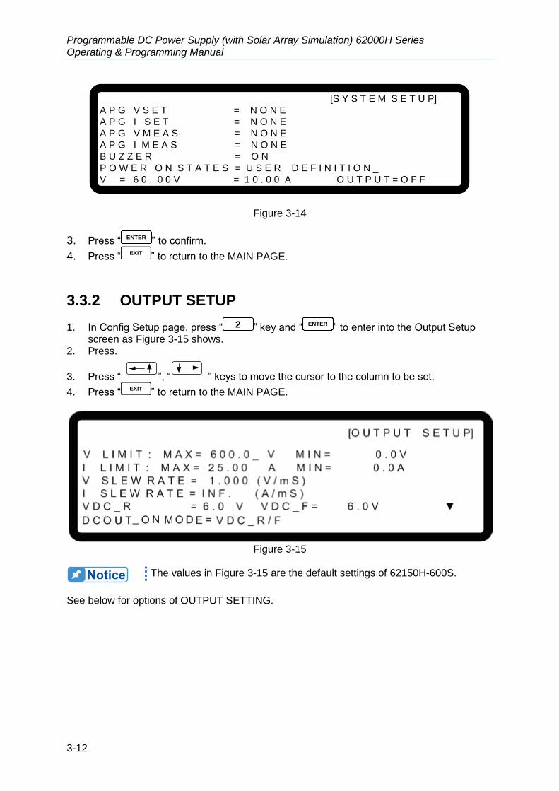
Programmable DC Power Supply (with Solar Array Simulation) 62000H Series Operating & Programming Manual
3-12
[S Y S T E M S E T U P]
A P G V S E T = N O N E
A P G I S E T = N O N E
A P G V M E A S = N O N E
A P G I M E A S = N O N E
B U Z Z E R = O N
P O W E R O N S T A T E S = U S E R D E F I N I T I O N _
V = 6 0 . 0 0 V = 1 0 . 0 0 A O U T P U T = O F F
Figure 3-14
3. Press “ENTER
” to confirm.
4. Press “ EXIT ” to return to the MAIN PAGE.
3.3.2 OUTPUT SETUP
1. In Config Setup page, press “ 2 ” key and “ENTER
” to enter into the Output Setup screen as Figure 3-15 shows.
2. Press.
3. Press “ ”, “ ” keys to move the cursor to the column to be set.
4. Press “ EXIT ” to return to the MAIN PAGE.
Figure 3-15
The values in Figure 3-15 are the default settings of 62150H-600S.
See below for options of OUTPUT SETTING.

Manual Operation
3-13
3.3.2.1 VOLTAGE LIMIT SETTING
1. Use “ ”, “ ” keys to move the cursor to the column to be set as Figure 3-16 shows.
Figure 3-16
2. Use the numeric keys ( 0 ~ 9 ) or “Rotary” (
) knob to set the value.
Use this option to narrow down the range by setting the MIN and MAX. When “ VOLT ” is pressed to set the output voltage, the DC Power Supply allows setting the voltage within the range of [MIN value ≤ user-defined value ≤ MAX value]. As example use the 62150H-600S, the V LIMIT: MAX=100V, MIN=20V. If the setting exceeds the output voltage 110V set by the user, the BUZZER will beep one time (if BUZZER is set to ON) and the main screen will prompt a warning message automatically as shown in Figure 3-17 below.
V = 6 0. 0 0 V I = 1 0. 0 0 _ A O F F
0 . 0 0 0 0 V 0 . 0 0 0 0 AV L I M I T R A N G E = 2 0 . 0 V – 1 0 0 . 0 V
Figure 3-17
3. Press “ENTER
” to confirm. 4. Press “ EXIT ” to return to the MAIN PAGE.
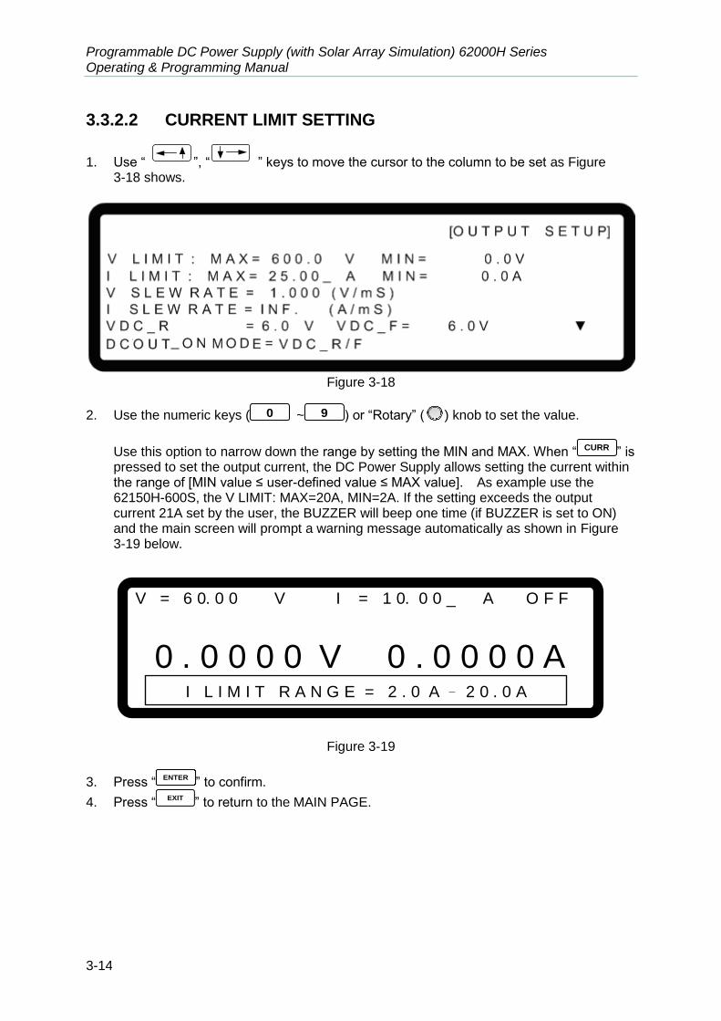
Programmable DC Power Supply (with Solar Array Simulation) 62000H Series Operating & Programming Manual
3-14
3.3.2.2 CURRENT LIMIT SETTING
1. Use “ ”, “ ” keys to move the cursor to the column to be set as Figure 3-18 shows.
Figure 3-18
2. Use the numeric keys ( 0 ~ 9 ) or “Rotary” (
) knob to set the value.
Use this option to narrow down the range by setting the MIN and MAX. When “ CURR ” is pressed to set the output current, the DC Power Supply allows setting the current within the range of [MIN value ≤ user-defined value ≤ MAX value]. As example use the 62150H-600S, the V LIMIT: MAX=20A, MIN=2A. If the setting exceeds the output current 21A set by the user, the BUZZER will beep one time (if BUZZER is set to ON) and the main screen will prompt a warning message automatically as shown in Figure 3-19 below.
V = 6 0. 0 0 V I = 1 0. 0 0 _ A O F F
0 . 0 0 0 0 V 0 . 0 0 0 0 AI L I M I T R A N G E = 2 . 0 A – 2 0 . 0 A
Figure 3-19
3. Press “ENTER
” to confirm.
4. Press “EXIT
” to return to the MAIN PAGE.

Manual Operation
3-15
3.3.2.3 VOLTAGE SLEW RATE
1. Use “ ”, “ ” keys to move the cursor to the column to be set as Figure 3-20 shows.
Figure 3-20
2. Use the numeric keys ( 0 ~ 9 ) or “Rotary” (
) knob to set the value. Take example by 62150H-600S, the output voltage slew rate of the DC Power Supply is set as Figure 3-21 shows. The maximum input Slew Rate is 20V/mS and the minimum is 0.001V/mS. The output of DC Power Supply will use the slew rate to rise to the set output voltage while the fall slew rate is limited by load.
Vo
Time(mS)Δ T
Δ V
VSR
T
Figure 3-21
3. Press “ENTER
” to confirm. 4. Press “ EXIT ” to return to the MAIN PAGE.
The minimum transient time is (ΔT) = 0.5 ms.
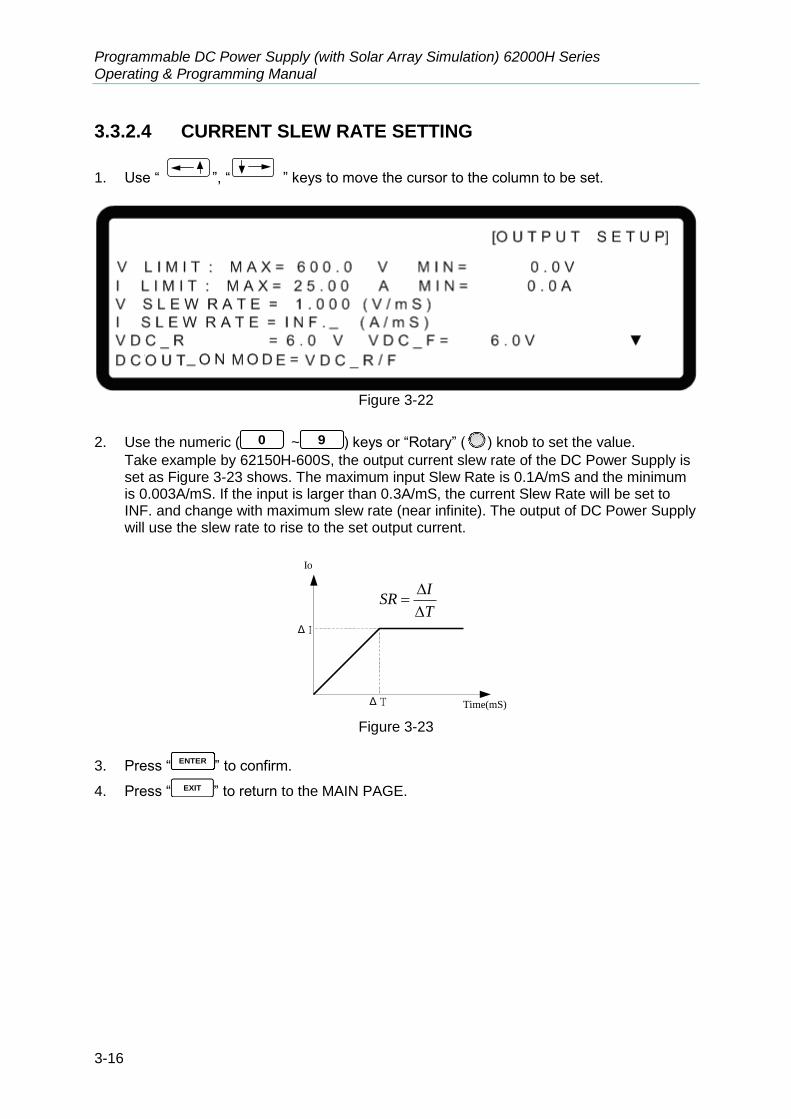
Programmable DC Power Supply (with Solar Array Simulation) 62000H Series Operating & Programming Manual
3-16
3.3.2.4 CURRENT SLEW RATE SETTING
1. Use “ ”, “ ” keys to move the cursor to the column to be set.
Figure 3-22
2. Use the numeric ( 0 ~ 9 ) keys or “Rotary” (
) knob to set the value. Take example by 62150H-600S, the output current slew rate of the DC Power Supply is set as Figure 3-23 shows. The maximum input Slew Rate is 0.1A/mS and the minimum is 0.003A/mS. If the input is larger than 0.3A/mS, the current Slew Rate will be set to INF. and change with maximum slew rate (near infinite). The output of DC Power Supply will use the slew rate to rise to the set output current.
Δ T
Δ I
ISR
T
Time(mS)
Io
Figure 3-23
3. Press “ENTER
” to confirm.
4. Press “ EXIT ” to return to the MAIN PAGE.
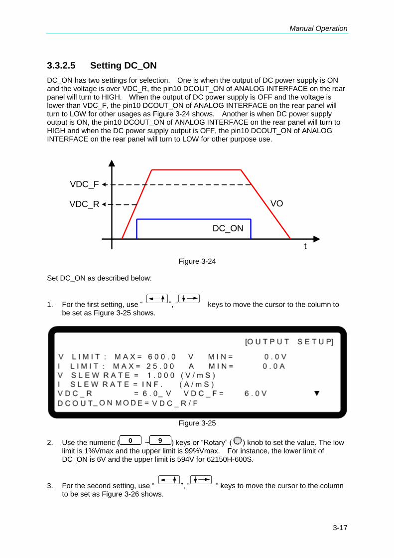
Manual Operation
3-17
3.3.2.5 Setting DC_ON
DC_ON has two settings for selection. One is when the output of DC power supply is ON and the voltage is over VDC_R, the pin10 DCOUT_ON of ANALOG INTERFACE on the rear panel will turn to HIGH. When the output of DC power supply is OFF and the voltage is lower than VDC_F, the pin10 DCOUT_ON of ANALOG INTERFACE on the rear panel will turn to LOW for other usages as Figure 3-24 shows. Another is when DC power supply output is ON, the pin10 DCOUT_ON of ANALOG INTERFACE on the rear panel will turn to HIGH and when the DC power supply output is OFF, the pin10 DCOUT_ON of ANALOG INTERFACE on the rear panel will turn to LOW for other purpose use.
VDC_R
VDC_F
t
VO
DC_ON
Figure 3-24
Set DC_ON as described below:
1. For the first setting, use “ ”, “ keys to move the cursor to the column to be set as Figure 3-25 shows.
Figure 3-25
2. Use the numeric ( 0 ~ 9 ) keys or “Rotary” (
) knob to set the value. The low limit is 1%Vmax and the upper limit is 99%Vmax. For instance, the lower limit of DC_ON is 6V and the upper limit is 594V for 62150H-600S.
3. For the second setting, use “ ”, “ ” keys to move the cursor to the column to be set as Figure 3-26 shows.

Programmable DC Power Supply (with Solar Array Simulation) 62000H Series Operating & Programming Manual
3-18
Figure 3-26
4. Use the numeric ( 0 ~ 1 ) keys or “Rotary” (
) knob to set DCOUT ON MODED to ON/OFF making the pin10 of ANALOG INTERFACE to receive command from the OUTPUT button on the front panel.
3.3.2.6 Setting IV CURVE Parameters
The IV Curve related parameters such as CONTROL MODE, INPUT FILTER, OUTPUT SPEED and SETTING MARGIN can be modified in IV CURVE PARAMETER as Figure 3-27 shows. The settings of IV CURVE PARAMETER can adjust the IV Curve algorithm in Table mode, SAS mode and IV Program.
[O U T P U T S E T U P]
I V C U R V E P A R A M E T E R: C O N T R O L M O D E = C C M O D E _
I N P U T F I L T E R = 1 0 0 0 Hz
O U T P U T S P E E D = M I D D L E
S E T T I N G M A R G I N = 3 %
▲
Figure 3-27
3.3.2.6.1 Setting CONTROL MODE
When the DC Power Supply is operating in IV mode, the CONTROL MODE will affect the IV Curve settings and the measured object. When set to CC mode, the DC Power Supply will measure the output voltage and use the IV Curve mapped current to be the control current to draw the set IV Curve as Figure 3-28(a) shows. If the CONTROL MODE is set to CV mode, the DC Power Supply will measure the output current and use the IV Curve mapped voltage to be the controlled voltage to draw out the set IV Curve as Figure 3-28(b) shows.

Manual Operation
3-19
Voc
Isc
V1
Iset1
V2
Iset2
(a) CC Mode
Voc
Isc
Vset1
I1
Vset2
I2
(b) CV Mode
Voc
Isc
V1
Iset1
V2
Iset2
Voc
Isc
V1
Iset1
V2
Iset2
(a) CC Mode
Voc
Isc
Vset1
I1
Vset2
I2
(b) CV Mode
Figure 3-28 Set CONTROL MODE as described below:
1. Use “ ”, “ ” keys to move the cursor to the column to be set as Figure 3-27 shows.
2. Use the numeric ( 0 ~ 1 ) keys or “Rotary” (
) knob to set it to CC MODE or CV MODE. The default setting is CC MODE.
3. Press “ENTER
” to confirm.
4. Press “ EXIT ” to return to the MAIN PAGE.
3.3.2.6.2 Setting INPUT FILTER
INPUT FILTER is to filter the measured signals for IV Curve calculation used in IV mode. For instance, if the measured voltage waveform has 20kHz ripple then setting the INPUT FILTER to 1kHz can eliminate the 20kHz ripple component.
1. Use “ ”, “ ” keys to move the cursor to the column to be set as Figure 3-29 shows.
[O U T P U T S E T U P]
I V C U R V E P A R A M E T E R: C O N T R O L M O D E = C C M O D E
I N P U T F I L T E R = 1 0 0 0 Hz _
O U T P U T S P E E D = M I D D L E
S E T T I N G M A R G I N = 3 %
▲
Figure 3-29
2. Use the numeric ( 0 ~ 9 ) keys or “Rotary” (
) knob to set the INPUT FILTER frequency. The setting range is 1~3125Hz and the default is 1000Hz.
3. Press “ENTER
” to confirm.
4. Press “EXIT
” to return to the MAIN PAGE.

Programmable DC Power Supply (with Solar Array Simulation) 62000H Series Operating & Programming Manual
3-20
3.3.2.6.3 Setting OUTPUT SPEED
OUTPUT SPEED is to set the output response speed of IV Curve to FAST, MIDDLE or SLOW. The setting of output response speed is in the sequence of FAST > MIDDLE > SLOW.
1. Use “ ”, “ ” keys to move the cursor to the column to be set as Figure 3-30 shows.
[O U T P U T S E T U P]
I V C U R V E P A R A M E T E R: C O N T R O L M O D E = C C M O D E
I N P U T F I L T E R = 1 0 0 0 Hz
O U T P U T S P E E D = M I D D L E _
S E T T I N G M A R G I N = 3 %
▲
Figure 3-30
2. Use the numeric ( 0 ~ 2 ) keys or “Rotary” (
) knob to set the OUTPUT SPEED. The default is MIDDLE.
3. Press “ENTER
” to confirm.
4. Press “ EXIT ” to return to the MAIN PAGE.
3.3.2.6.4 Setting MARGIN
SETTING MARGIN is to set the margin of non-control settings in IV Curve. For instance, when set to CC mode, the non-control item is the voltage setting and vice versa it is the current setting when set to CV mode. To ensure the control mode is able to remain in a fixed mode, the setting has to be larger than 3%. As Figure 3-28(a) shows the voltage measurement is V1 so the control item is the current setting that is Iset1 instead of Vset1. Thus, when the SETTING MARGIN is set to 3%, the Vset1=1.03*V1.
1. Use “ ”, “ ” keys to move the cursor to the column to be set as Figure 3-31.
[O U T P U T S E T U P]
I V C U R V E P A R A M E T E R: C O N T R O L M O D E = C C M O D E
I N P U T F I L T E R = 1 0 0 0 Hz
O U T P U T S P E E D = M I D D L E
S E T T I N G M A R G I N = 3 % _
▲
Figure 3-31

Manual Operation
3-21
2. Use the numeric keys ( 0 ~ 9 ) or “Rotary” (
) knob to set the range of SETTING MARGIN. The default is 3%.
3. Press “ENTER
” to confirm.
4. Press “ EXIT ” to return to the MAIN PAGE.
3.3.3 SERIES/PARALLEL
62000H Series DC Power Supplies with Solar Array Simulation are able to operate in series or parallel when in the common CV/CC MODE. The voltage is up to 1200V if connecting in series and the current is up to 250A if connecting in parallel. When the IV curve function is enabled that is in TABLE Mode, SAS Mode and IV PROGRAM Mode, only parallel connection is supported with no series connection.
1. Series/Parallel cannot be mixed in use. A620028 and A620027
models support parallel connection only. 2. The maximum output voltage or current is 1200V or 250A when
operating the 62000H Series with Solar Array Simulation in series or parallel. Table 3-1 lists the example of 62150H-600S.
Table 3-1
62000H Series Model with Solar Array Simulation
Serial Parallel
Max. Devices
Max. Output Voltage (V)
Max. Devices
Max. Output Current (A)
62150H-600S 2 1200 10 250
62150H-1000S 2 1200 10 150
62020H-150S 2 250 10 400
3. Different model is unable to be operated in parallel or serial. 4. Be sure the breaker capacity is enough and the earth wire is
grounded to earth ground when series/parallel is in use. 5. When the devices to be paralleled are over 5 sets (>5), please
contact the Service Center or agent of CHROMA. 6. Please configure the DC Power Supplies up and down stack for
parallel connection. The standard CURRENT SHARING cable is unable to use if placing the devices lateral for parallel configuration. It is necessary to purchase another optional CURRENT SHARING (100CM) cable for use. Please contact CHROMA Service Center or local agent for further information. Also, be noted that the paralleled devices cannot exceed 2 units when placing lateral.
7. Firmware version 2.00 or above is not backward compatible. Be sure to upgrade the device with firmware 1.XX to 2.00 when connecting to a device with firmware 2.00 for series or parallel operation. Please contact the service unit for firmware upgrade.

Programmable DC Power Supply (with Solar Array Simulation) 62000H Series Operating & Programming Manual
3-22
3.3.3.1 Connecting Series/Parallel Output Cable
Figure 3-32 and Figure 3-33 show the connections of serial and parallel output cables.
SVO+VO+
VO
SVO
SVO+
VO+
VO-
SVO
DUT
SVO+VO+
VO
SVO
SVO+
VO+
VO -
SVO
DUT
62150H-600S
62150H-600S
--
----
+
-
Figure 3-32
SVO+
VO+
VO-
SVO-
SVO+
VO+
VO-
SVO-
SVO+
VO+
VO-
SVO-
SVO+
VO+
VO-
SVO-
SVO+
VO+
VO-
SVO-
DUT
SVO+
VO+
VO-
SVO-
SVO+
VO+
VO-
SVO-
SVO+
VO+
VO-
SVO-
SVO+
VO+
VO-
SVO-
SVO+
VO+
VO-
SVO-
DUT
62150H-600S
62150H-600S
62150H-600S
62150H-600S
62150H-600S
+
-
Figure 3-33
3.3.3.2 Assembling Series/Parallel Communication Interface
1. When the DC Power Supply is connecting in series for operation, the SYSTEM BUS connectors on the rear panel must be connected as shown in Figure 3-34(a.) For Model 62020H-150S, connect the cables as shown in Figure 3-34(b)
CURRENT
SHARING
CURRENT
SHARING
1 #
2 #
[ SYSTEM BUS]
[ SYSTEM BUS]
(a) (b)
Figure 3-34

Manual Operation
3-23
2. When the DC Power Supply is connecting in parallel for operation, besides the SYSTEM
BUS connectors on the rear panel need to be connected, the CURRENT SHARING
connectors have to be connected too as shown in Figure 3-35 (a) and Figure 3-35 (b) for Model 62020H-150S. For A620028 and A620027, besides the above connection the MASTER unit and ANALOG have to be connected as well for power on as shown in Figure 3-36.
1. A620028 and A620027 SLAVE models only work when the
MASTER firmware version is 1.30 or above for communication. For firmware upgrade, please contact the agent of Chroma.
2. A620028 and A620027 SLAVE models have a 1 to 2 ANALOG communication cable labeled with SLAVE. This standard accessory is for A620028 and A620027 use only. The other 1 to 2 ANALOG cable labeled with MASTER is to connect the MASTER side to communicate with A620028 and A620027 for power on as the installation shows in Figure 3-36 and this cable is optional.
3. Plug in the 62020H-150S SYSTME BUS CABLE connector labeled with REAL to the device rear panel. See Figure 3-35(b) for connecting other devices for communication.
CURRENT
SHARING
CURRENT
SHARING
CURRENT
SHARING
CURRENT
SHARING
1 #
2 #
10 #
9#
[ SYSTEM BUS]
[ SYSTEM BUS]
[ SYSTEM BUS]
[ SYSTEM BUS]
(a) (b)
Figure 3-35
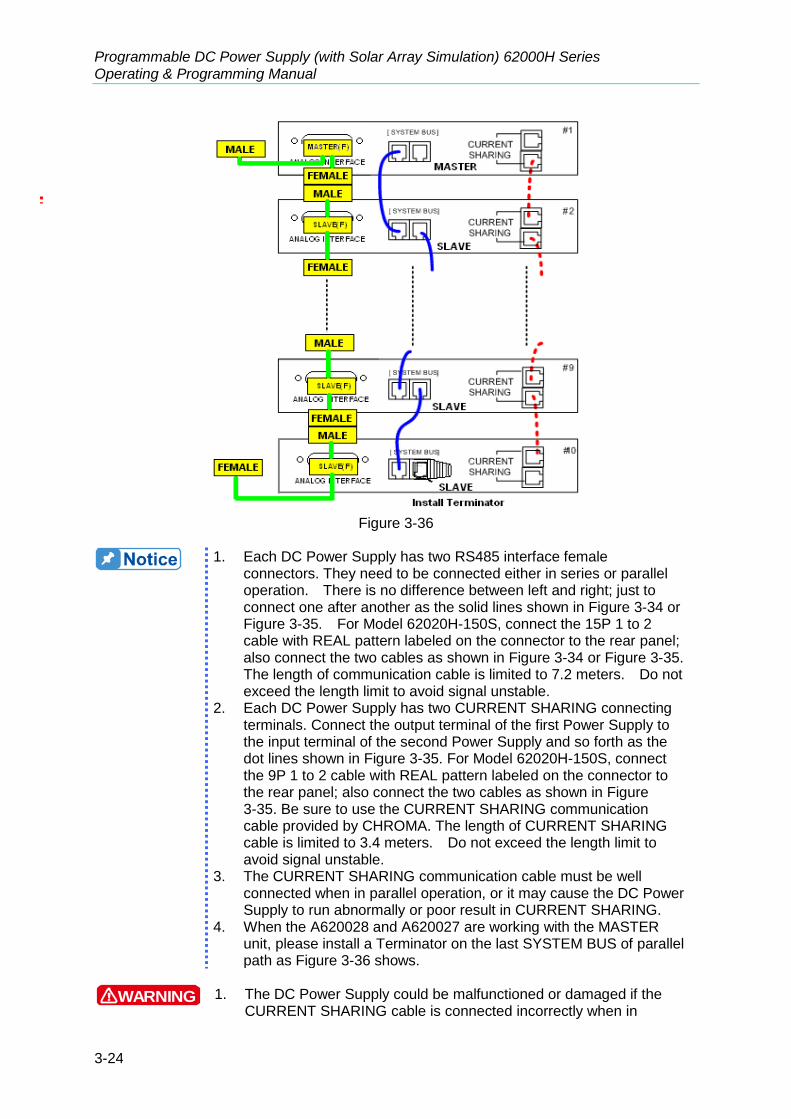
Programmable DC Power Supply (with Solar Array Simulation) 62000H Series Operating & Programming Manual
3-24
Figure 3-36
1. Each DC Power Supply has two RS485 interface female
connectors. They need to be connected either in series or parallel operation. There is no difference between left and right; just to connect one after another as the solid lines shown in Figure 3-34 or Figure 3-35. For Model 62020H-150S, connect the 15P 1 to 2 cable with REAL pattern labeled on the connector to the rear panel; also connect the two cables as shown in Figure 3-34 or Figure 3-35. The length of communication cable is limited to 7.2 meters. Do not exceed the length limit to avoid signal unstable.
2. Each DC Power Supply has two CURRENT SHARING connecting terminals. Connect the output terminal of the first Power Supply to the input terminal of the second Power Supply and so forth as the dot lines shown in Figure 3-35. For Model 62020H-150S, connect the 9P 1 to 2 cable with REAL pattern labeled on the connector to the rear panel; also connect the two cables as shown in Figure 3-35. Be sure to use the CURRENT SHARING communication cable provided by CHROMA. The length of CURRENT SHARING cable is limited to 3.4 meters. Do not exceed the length limit to avoid signal unstable.
3. The CURRENT SHARING communication cable must be well connected when in parallel operation, or it may cause the DC Power Supply to run abnormally or poor result in CURRENT SHARING.
4. When the A620028 and A620027 are working with the MASTER unit, please install a Terminator on the last SYSTEM BUS of parallel path as Figure 3-36 shows.
WARNING 1. The DC Power Supply could be malfunctioned or damaged if the
CURRENT SHARING cable is connected incorrectly when in

Manual Operation
3-25
parallel mode.
2. Do not connect the CURRENT SHARING cable when in series operation or it could be malfunctioned or damaged.
3. Do not connect the CURRENT SHARING cable when operated standalone, or it could cause the power supply to be malfunctioned or damaged.
4. Be sure to remove the SYSTEM BUS and CURRENT SHARING signal cables when returning to standalone operation or it could cause the power supply to be malfunctioned or damaged.
3.3.3.3 Setting Series/Parallel Operation Mode
3.3.3.3.1 Setting SLAVE
CAUTION It is necessary to set the SLAVE first and the MASTER last when operating a 62000H Series DC Power Supply with Solar Array Simulation in series or parallel mode, or it may not be able to operate due to communication error.
When MASTER OR SLAVE sets to SLAVE, it has to set the SLAVE to SLAVE1 ~ SLAVE9
and M/S TERMINATOR selection. Set the SLAVE in sequence starting from SLAVE1.
1. In Config Setup page, press “ 3 ” and “ENTER
” to select PARALLEL /SERIES and display Figure 3-37.
2. Use “ ”, “ ” keys to move the cursor to the PARALLEL OR SERIES selection column.
[ S E R I E S / P A R A L L E L ]
M A S T E R O R S L A V E = M A S T E R _
M / S T E R M I N A T O R = D I S A B L E
P A R A L L E L O R S E R I E S = P A R A L L E L
N U M . O F S L A V E = 1
M A S T E R & S L A V E C O N T R O L = N O
Figure 3-37
3. Use the numeric ( 1 ~ 9 ) keys or “Rotary” (
) knob to set SLAVE1~SLAVE9 as Figure 3-38 shows.

Programmable DC Power Supply (with Solar Array Simulation) 62000H Series Operating & Programming Manual
3-26
[ S E R I E S / P A R A L L E L ]
M A S T E R O R S L A V E = S L A V E 1 _
M / S T E R M I N A T O R = D I S A B L E
Figure 3-38
4. Use “ ”, “ ” keys to move the cursor to the M/S TERMINATOR selection item.
5. Use the numeric ( 1 ~ 0 ) key or “Rotary” (
) knob to ENABLE or DISABLE the TERMINATOR as Figure 3-38 shows.
6. Press “ENTER
” to confirm.
7. Press “EXIT
” to return to the MAIN PAGE.
3.3.3.3.2 Setting MASTER
If MASTER OR SLAVE is set to MASTER, it has to set M/S TERMINATOR, PARALLEL OR
SERIES and NUM. OF SLAVE selections. See the description of PARALLEL OR SERIES in
section 0 and NUM. OF SLAVE in section 3.3.3.3.4.
MASTER has two main functions: (1) It issues commands to all SLAVE, such as voltage setting, current setting, protection
setting and etc., which means all settings in SALVE are from MASTER. The original settings in SLAVE are temporary invalid.
(2) It accepts all measurement values and protection signals from SLAVE. The MASTER calculates all measurement values and displays them in the main page. Moreover, when protection is occurred in one SLAVE, the MASTER will notify other SLAVE to set off the protection and show in the MASTER’s main page.
When multiple DC Power Supplies are connected in series or parallel, only one DC Power Supply can be the Master and the rest have to be set to Slave.
Set MASTER as described below:
1. In Config Setup page, press “ 3 ” and ENTER
to select PARALLEL/SERIES.
2. Use the numeric ( 0 ) key or “Rotary” (
) knob to set MASTER as Figure 3-39 shows.

Manual Operation
3-27
[ S E R I E S / P A R A L L E L ]
M A S T E R O R S L A V E = M A S T E R _
M / S T E R M I N A T O R = D I S A B L E
P A R A L L E L O R S E R I E S = P A R A L L E L
N U M . O F S L A V E = 1
M A S T E R & S L A V E C O N T R O L = N O
Figure 3-39
3. Use “ ”, “ ” keys to move the cursor to the M/S TERMINATOR selection item.
4. Use the numeric ( 1 ~ 0 ) key or “Rotary” (
) knob to ENABLE or DISABLE the TERMINATOR as Figure 3-39 shows.
5. Press “ENTER
” to confirm.
Description of M/S TERMINATOR When the 62000H Series Models with Solar Array Simulation are operating in MASTER OR SLAVE mode, please be aware of the M/S TERMINATOR setting. Assuming the connection is as Figure 3-40 shows, the M/S TERMINATOR of the first and last devices must be ENABLED with 120Ω internal resistance. If it is A620028 and A620027 SLAVE models, the TERMINATOR is installed externally as Figure 3-36 shows.
Figure 3-40
3.3.3.3.3 Setting PARALLEL or SERIES
This option is to set the Power Supply to be operated in Series or Parallel mode as Figure
3-41 shows. There are two selections: PARALLEL and SERIES.
1. Use “ ”, “ ” keys to move the cursor to the column to be set.
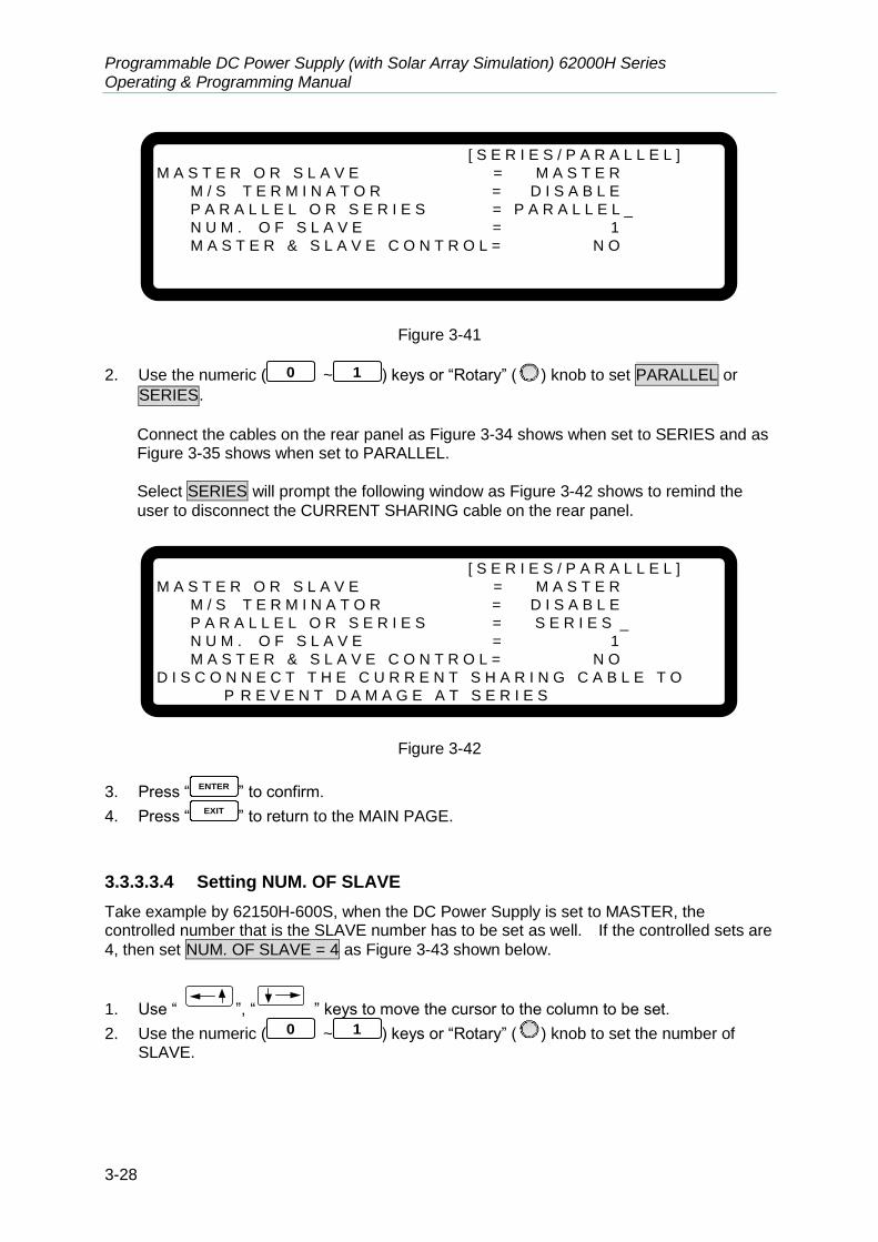
Programmable DC Power Supply (with Solar Array Simulation) 62000H Series Operating & Programming Manual
3-28
[ S E R I E S / P A R A L L E L ]
M A S T E R O R S L A V E = M A S T E R
M / S T E R M I N A T O R = D I S A B L E
P A R A L L E L O R S E R I E S = P A R A L L E L _
N U M . O F S L A V E = 1
M A S T E R & S L A V E C O N T R O L = N O
Figure 3-41
2. Use the numeric ( 0 ~ 1 ) keys or “Rotary” (
) knob to set PARALLEL or
SERIES.
Connect the cables on the rear panel as Figure 3-34 shows when set to SERIES and as Figure 3-35 shows when set to PARALLEL.
Select SERIES will prompt the following window as Figure 3-42 shows to remind the
user to disconnect the CURRENT SHARING cable on the rear panel.
[ S E R I E S / P A R A L L E L ]
M A S T E R O R S L A V E = M A S T E R
M / S T E R M I N A T O R = D I S A B L E
P A R A L L E L O R S E R I E S = S E R I E S _
N U M . O F S L A V E = 1
M A S T E R & S L A V E C O N T R O L = N O
D I S C O N N E C T T H E C U R R E N T S H A R I N G C A B L E T O
P R E V E N T D A M A G E A T S E R I E S
Figure 3-42
3. Press “ENTER
” to confirm.
4. Press “EXIT
” to return to the MAIN PAGE.
3.3.3.3.4 Setting NUM. OF SLAVE
Take example by 62150H-600S, when the DC Power Supply is set to MASTER, the controlled number that is the SLAVE number has to be set as well. If the controlled sets are
4, then set NUM. OF SLAVE = 4 as Figure 3-43 shown below.
1. Use “ ”, “ ” keys to move the cursor to the column to be set.
2. Use the numeric ( 0 ~ 1 ) keys or “Rotary” (
) knob to set the number of SLAVE.

Manual Operation
3-29
[ S E R I E S / P A R A L L E L ]
M A S T E R O R S L A V E = M A S T E R
M / S T E R M I N A T O R = D I S A B L E
P A R A L L E L O R S E R I E S = P A R A L L E L
N U M . O F S L A V E = 4 _
M A S T E R & S L A V E C O N T R O L = N O
Figure 3-43
3. Press “ENTER
” to confirm.
4. Press “EXIT
” to return to the MAIN PAGE.
Take example by 62150H-600S: 1. If there are 5 sets connected in parallel and 600V/100A is set, the
setting of each set is 600V/20A and the total output will be 600V/100A.
2. If there are 2 sets connected in series and 1200V/25A is set, the setting of each set is 600V/25A and the total output will be 1200V/25A.
3. The total sets for connecting in series are 2; therefore, the
maximum number of NUM. OF SLAVE is 1.
4. The total sets for connecting in parallel are 10; therefore, the
maximum number of NUM. OF SLAVE is 9.
3.3.3.3.5 Activating MASTER & SLAVE CONTROL
When PARALLEL OR SERIES, NUM. OF SLAVE are set for MASTER, it is able to use MASTER to activate the series/parallel control as described below:
1. Use “ ”, “ ” keys to move the cursor to the column to be set as Figure 3-44 shows.
2. Use the numeric ( 1 ) key or “Rotary” (
) knob to set YES。
[ S E R I E S / P A R A L L E L ]
M A S T E R O R S L A V E = M A S T E R
M / S T E R M I N A T O R = D I S A B L E
P A R A L L E L O R S E R I E S = P A R A L L E L
N U M . O F S L A V E = 4
M A S T E R & S L A V E C O N T R O L = Y E S _
Figure 3-44

Programmable DC Power Supply (with Solar Array Simulation) 62000H Series Operating & Programming Manual
3-30
3. Press “ENTER
to confirm, it will skip to the series/parallel MASTER page automatically as Figure 3-45 shows.
∑ V = 6 0. 0 0 _ V I = 1 0. 0 0 A M S T O F F
0 . 0 0 0 0 V 0 . 0 0 0 0 A 0 . 0 W
Figure 3-45
4. The SLAVE page will skip to Figure 3-46 automatically.
O N L I N E
S L A V E 1
Figure 3-46 5. Start the series/parallel usage.
CAUTION 1. Communication error will occur if the SLAVE settings are the same
(such as SLAVE 1 & SLAVE 1). The MAIN PAGE of MASTER will
show as Figure 3-47. When this type of error occurs, exit the series/parallel operation first and then change the SLAVE setting to resume the operation.
S L A V E 1
M E A S . E R R
Figure 3-47
2. Once the series/parallel is set, the settings can be saved. After all
machines are powered off, turn on the SLAVE first and MASTER the last, it will set series/ parallel operation automatically.

Manual Operation
3-31
3.3.3.4 Setting Series Parameters
When the software communication and hardware settings for series are completed, the settings of following windows are introduced in the sections underneath - (1) MAIN PAGE, (2) SYSTEM SETUP, (3) OUTPUT SETUP and (4) PROTECTION.
3.3.3.4.1 Setting MAIN PAGE
MAIN PAGE is mainly used to set voltage (V) and current (I). The difference between single unit and series operation is that the voltage set will increase following the number connected
in series. The voltage set is indicated by ΣV for easy identification. When set to MASTER,
MST will appear at the window’s upper right corner as Figure 3-48 shows below.
∑ V = 6 0. 0 0 _ V I = 1 0. 0 0 A M S T O F F
0 . 0 0 0 0 V 0 . 0 0 0 0 A 0 . 0 W
Figure 3-48
3.3.3.4.2 Setting SYSTEM SETUP for Series
The operation of POWER ON STATUS in SYSTEM SETUP for series is the same as single
unit; only the output voltage will increase following the number of machines set in series. For example if there are 2 sets of 62150H-600S in series, the maximum output voltage can be set is 1200V, and the maximum output current is 25A as Figure 3-49 shows below:
[S Y S T E M S E T U P]
A P G V S E T = N O N E
A P G I S E T = N O N E
A P G V M E A S = N O N E
A P G I M E A S = N O N E
B U Z Z E R = O N
P O W E R O N S T A T E S = U S E R D E F I N I T I O N _
∑ V = 1 2 0 0 . 0 0 V I =2 5 . 0 0 0 A O U T P U T = O F F
Figure 3-49
It will return to single unit mode once the POWER ON STATUS is set in series mode. The POWER ON STATUS sets the output voltage and current to 0 and OUTPUT to OFF automatically.

Programmable DC Power Supply (with Solar Array Simulation) 62000H Series Operating & Programming Manual
3-32
3.3.3.4.3 Setting OUTPUT SETUP for Series
The V LIMIT MAX in OUTPUT SETUP of MASTER for series connection will increase
following the number connected in series. It is indicated by ΣV LIMIT MAX: for easy
identification as Figure 3-50 shows below. Furthermore, the setting range of ΣV SLEW
RATE will increase following the number connected in series too.
[O U T P U T S E T U P]
ΣV L I M I T : M A X = 6 0 0 . 0 _ V M I N = 0 . 0 V
I L I M I T : M A X = 2 5 . 0 0 A M I N = 0 . 0 A
ΣV S L E W R A T E = 1 . 0 0 0 ( V / m S )
I S L E W R A T E = I N F . ( A / m S )
V D C _ R = 6 . 0 V V D C _ F = 6 . 0 V ▼
Figure 3-50
3.3.3.4.4 Setting PROTECTION for Series
The OVP and OPP in PROTECTION of MASTER for series connection will increase
following the number connected in series. It is indicated by ΣOVP and ΣOPP for easy
identification as Figure 3-51 shows below.
[ P R O T E C T I O N ]
∑ O V P = 6 0 0 . 0 _ V
O C P = 1 8 . 9 0 A
∑ O P P = 1 0 5 0 0 . 0 W
R E M O T E I N H I B I T = D I S A B L E P U L L = H I G H
S A F E T Y I N T . L O C K = D I S A B L E P U L L = H I G H
E X T O N / O F F = D I S A B L E P U L L = H I G H
Figure 3-51
3.3.3.5 Setting Parallel Parameters
When the software communication and hardware settings for parallel are completed, the settings of following windows are introduced in the sections underneath - (1) MAIN PAGE, (2) SYSTEM SETUP and (3) OUTPUT SETUP.
3.3.3.5.1 Setting MAIN PAGE
MAIN PAGE is mainly used to set voltage (V) and current (I). The difference between single unit and parallel operation is that the current set will increase following the number
connected in parallel. The current set is indicated by ΣI for easy identification. When set

Manual Operation
3-33
to MASTER, MST will appear at the window’s upper right corner as Figure 3-52 shows below.
V = 6 0. 0 0 _ V ∑ I = 1 0. 0 0 A M S T O F F
0 . 0 0 0 0 V 0 . 0 0 0 0 A 0 . 0 W
Figure 3-52
3.3.3.5.2 Setting SYSTEM SETUP for Parallel
The operation of POWER ON STATUS in SYSTEM SETUP for parallel is the same as single
unit; only the output current will increase following the number of machines set in parallel. For example if there are 5 sets of 62150H-600S in parallel, the maximum output voltage can be set is 600V, and the maximum output current is 125A as Figure 3-53 shows below:
[S Y S T E M S E T U P]
A P G V S E T = N O N E
A P G I S E T = N O N E
A P G V M E A S = N O N E
A P G I M E A S = N O N E
B U Z Z E R = O N
P O W E R O N S T A T E S = U S E R D E F I N I T I O N _
∑ V = 6 0 0 . 0 0 V I = 1 2 5 . 0 0 A O U T P U T = O F F
Figure 3-53
It will return to single unit mode once the POWER ON STATUS is set in parallel mode. The POWER ON STATUS sets the output voltage and current to 0 and OUTPUT to OFF automatically.
3.3.3.5.3 Setting OUTPUT SETUP for Parallel
The I LIMIT MAX in OUTPUT SETUP of MASTER for parallel connection will increase
following the number connected in parallel. It is indicated by ΣI LIMIT MAX: for easy
identification as Figure 3-54 shows below. Furthermore, the setting range of ΣI SLEW
RATE will increase following the number connected in parallel too.
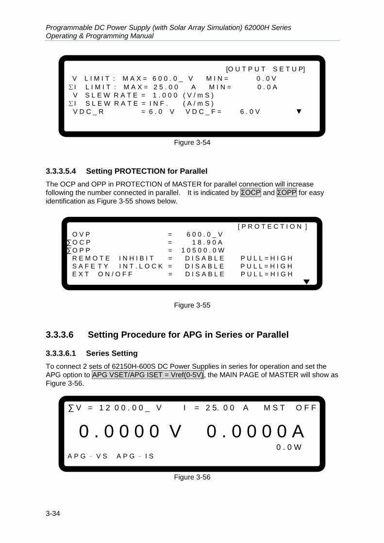
Programmable DC Power Supply (with Solar Array Simulation) 62000H Series Operating & Programming Manual
3-34
[O U T P U T S E T U P]
V L I M I T : M A X = 6 0 0 . 0 _ V M I N = 0 . 0 V
ΣI L I M I T : M A X = 2 5 . 0 0 A M I N = 0 . 0 A
V S L E W R A T E = 1 . 0 0 0 ( V / m S )
ΣI S L E W R A T E = I N F . ( A / m S )
V D C _ R = 6 . 0 V V D C _ F = 6 . 0 V ▼
Figure 3-54
3.3.3.5.4 Setting PROTECTION for Parallel
The OCP and OPP in PROTECTION of MASTER for parallel connection will increase
following the number connected in parallel. It is indicated by ΣOCP and ΣOPP for easy
identification as Figure 3-55 shows below.
[ P R O T E C T I O N ]
O V P = 6 0 0 . 0 _ V
∑ O C P = 1 8 . 9 0 A
∑ O P P = 1 0 5 0 0 . 0 W
R E M O T E I N H I B I T = D I S A B L E P U L L = H I G H
S A F E T Y I N T . L O C K = D I S A B L E P U L L = H I G H
E X T O N / O F F = D I S A B L E P U L L = H I G H
Figure 3-55
3.3.3.6 Setting Procedure for APG in Series or Parallel
3.3.3.6.1 Series Setting
To connect 2 sets of 62150H-600S DC Power Supplies in series for operation and set the
APG option to APG VSET/APG ISET = Vref(0-5V), the MAIN PAGE of MASTER will show as
Figure 3-56.
∑ V = 1 2 0 0 . 0 0 _ V I = 2 5. 0 0 A M S T O F F
0 . 0 0 0 0 V 0 . 0 0 0 0 A 0 . 0 W A P G – V S A P G – I S
Figure 3-56
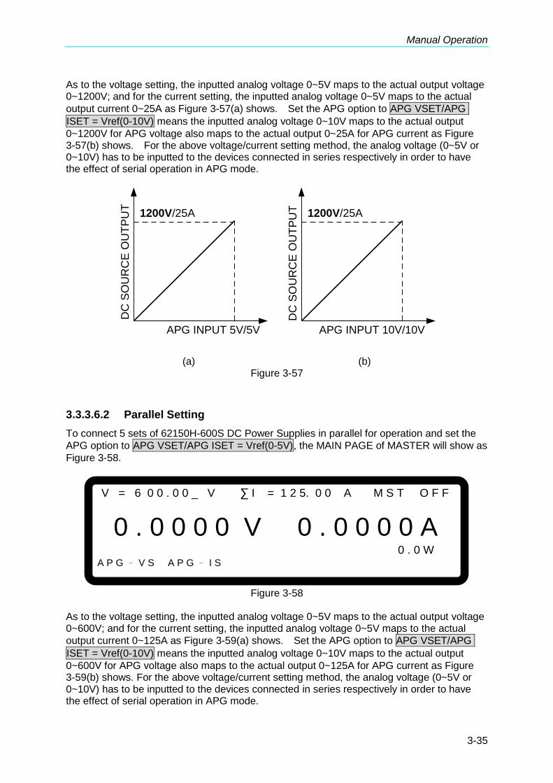
Manual Operation
3-35
As to the voltage setting, the inputted analog voltage 0~5V maps to the actual output voltage 0~1200V; and for the current setting, the inputted analog voltage 0~5V maps to the actual
output current 0~25A as Figure 3-57(a) shows. Set the APG option to APG VSET/APG
ISET = Vref(0-10V) means the inputted analog voltage 0~10V maps to the actual output
0~1200V for APG voltage also maps to the actual output 0~25A for APG current as Figure 3-57(b) shows. For the above voltage/current setting method, the analog voltage (0~5V or 0~10V) has to be inputted to the devices connected in series respectively in order to have the effect of serial operation in APG mode.
APG INPUT 5V/5V
DC
SO
UR
CE
OU
TP
UT
1200V/25A
APG INPUT 10V/10V
DC
SO
UR
CE
OU
TP
UT 1200V/25A
(a) (b)
Figure 3-57
3.3.3.6.2 Parallel Setting
To connect 5 sets of 62150H-600S DC Power Supplies in parallel for operation and set the
APG option to APG VSET/APG ISET = Vref(0-5V), the MAIN PAGE of MASTER will show as
Figure 3-58.
V = 6 0 0 . 0 0 _ V ∑ I = 1 2 5. 0 0 A M S T O F F
0 . 0 0 0 0 V 0 . 0 0 0 0 A 0 . 0 W A P G – V S A P G – I S
Figure 3-58
As to the voltage setting, the inputted analog voltage 0~5V maps to the actual output voltage 0~600V; and for the current setting, the inputted analog voltage 0~5V maps to the actual
output current 0~125A as Figure 3-59(a) shows. Set the APG option to APG VSET/APG
ISET = Vref(0-10V) means the inputted analog voltage 0~10V maps to the actual output
0~600V for APG voltage also maps to the actual output 0~125A for APG current as Figure 3-59(b) shows. For the above voltage/current setting method, the analog voltage (0~5V or 0~10V) has to be inputted to the devices connected in series respectively in order to have the effect of serial operation in APG mode.
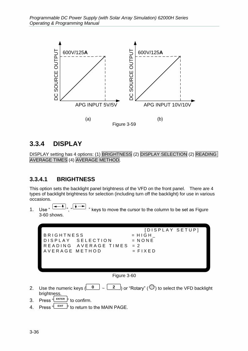
Programmable DC Power Supply (with Solar Array Simulation) 62000H Series Operating & Programming Manual
3-36
APG INPUT 5V/5V
DC
SO
UR
CE
OU
TP
UT
600V/125A
APG INPUT 10V/10V
DC
SO
UR
CE
OU
TP
UT
600V/125A
(a) (b)
Figure 3-59
3.3.4 DISPLAY
DISPLAY setting has 4 options: (1) BRIGHTNESS (2) DISPLAY SELECTION (2) READING
AVERAGE TIMES (4) AVERAGE METHOD.
3.3.4.1 BRIGHTNESS
This option sets the backlight panel brightness of the VFD on the front panel. There are 4 types of backlight brightness for selection (including turn off the backlight) for use in various occasions.
1. Use “ ”, “ ” keys to move the cursor to the column to be set as Figure 3-60 shows.
[ D I S P L A Y S E T U P ]
B R I G H T N E S S = H I G H _
D I S P L A Y S E L E C T I O N = N O N E
R E A D I N G A V E R A G E T I M E S = 2
A V E R A G E M E T H O D = F I X E D
Figure 3-60
2. Use the numeric keys ( 0 ~ 2 ) or “Rotary” (
) to select the VFD backlight brightness.
3. Press “ENTER
” to confirm.
4. Press “EXIT
” to return to the MAIN PAGE.

Manual Operation
3-37
1. There are 3 selections for BRIGHTNESS: HIGH /NORMAL/
DIMMED, the system default is HIGH. 2. Shortcuts and brightness description:
a. Press “ 0 ”, BRIGHTNESS = HIGH.
b. Press “ 1 ”, BRIGHTNESS = NORMAL.
c. Press “ 2 ”, BRIGHTNESS = DIMMED. 3. The lower the backlight brightness, the longer the display panel life.
Thus, it is suggested to turn the backlight brightness to DIMMED when the device is doing burn-in to prolong the product life of the VFD display.
3.3.4.2 DISPLAY SELECTION
The setting of DISPLAY is to show the internal settings on the last line of MAIN PAGE for easy identification without entering the setting page. There are 4 options available for
displaying on the MAIN PAGE: (1) NONE, (2) V/I LIMIT, (3) V/I/P PROTECT and (4) V/I
SLEWRATE.
1. In Config setting page, press “ 4 ” to display the screen and “ENTER
” to enter into DISPLAY SELECTION as Figure 3-61 shows.
[ D I S P L A Y S E T U P ]
B R I G H T N E S S = H I G H
D I S P L A Y S E L E C T I O N = N O N E _
R E A D I N G A V E R A G E T I M E S = 2
A V E R A G E M E T H O D = F I X E D
Figure 3-61
2. Use “ ”, “ ” keys to move the cursor to the column to be set as Figure 3-61 shows.
3. Use the numeric ( 0 ~ 3 ) key or “Rotary” (
) knob to select the desired
setting. There are 4 selections on the MAIN PAGE:(1)NONE, (2)V/I LIMIT, (3)V/I/P
PROTECT and (4)V/I SLEWRATE. The system default is NONE.
When the selection is set to NONE, the MAIN PAGE does not show any message on
the last line.
When it is set to V/I LIMIT, the MAIN PAGE last line will show the range set by V LIMIT
and I LIMIT in OUTPUT SETUP as Figure 3-62 shows. See section 3.3.2.1 and 3.3.2.2 for detail description.

Programmable DC Power Supply (with Solar Array Simulation) 62000H Series Operating & Programming Manual
3-38
V = 6 0. 0 0 V I = 1 0. 0 0 _ A O F F
0 . 0 0 0 0 V 0 . 0 0 0 0 A 0 . 0 W
V _ L I M : 2 0 . 0 – 1 0 0 . 0 I_ L I M : 2 . 0 0 – 1 8 . 0 0
Figure 3-62
When the selection is set to V/I /P PROTECT, the MAIN PAGE last line will show the
OVP, OCP and OPP settings in the PROTECTION as Figure 3-63 shows. See sections 3.3.5.1 ~3.3.5.3 for detail description.
V = 6 0. 0 0 V I = 1 0. 0 0 _ A O F F
0 . 0 0 0 0 V 0 . 0 0 0 0 A 0 . 0 W
O V P = 6 6 0 . 0 V O C P = 1 8 . 9 0 A O P P = 1 0 5 0 0 . 0 W
Figure 3-63
When the selection is set to V/I SLEW, the MAIN PAGE last line will show the settings of
V SLEWRATE and I SLEWRATE in OUTPUT SETUP as Figure 3-64 shows. See section 3.3.2.3 and 3.3.2.4 for detail description
V = 6 0. 0 0 V I = 1 0. 0 0 _ A O F F
0 . 0 0 0 0 V 0 . 0 0 0 0 A 0 . 0 W
V _ S / R : 1 0 .0 0 0 ( V / m s ) I _ S / R : 0 . 0 0 1 ( A / m s )
Figure 3-64

Manual Operation
3-39
3.3.4.3 READING AVERAGE TIMES
READING AVERAGE TIMES option can set the average times the MAIN PAGE displays.
The default is 2 as Figure 3-65 shows. When changing the READING AVERAGE TIMES
default, the average method can be changed.
[ D I S P L A Y S E T U P ]
B R I G H T N E S S = H I G H
D I S P L A Y S E L E C T I O N = N O N E
R E A D I N G A V E R A G E T I M E S = 2 _
A V E R A G E M E T H O D = F I X E D
Figure 3-65
Follow the steps below to change the average times and method:
1. Use “ ”, “ ” keys to move the cursor to the column to be set.
2. Use the numeric keys 0 ~ 3 or “Rotary” (
) to select the desired average
times. READING AVERAGE TIME can be set to 1, 2, 4 and 8.
3. Move the cursor to AVERAGE METHOD and use the numeric keys ( 0 ~ 1 )
or “Rotary” (
) to select the desired average method. AVERAGE METHOD has
FIXED and MOVING 2 types.
1. Assuming setting the READING AVERAGE TIME = 8, AVERAGE
METHOD:FIXED, readings sampling is that the device clears all of the old samples (A1 ~ A8) in the buffer and saves the new samples (B1 ~ B8), then averages them in repetition as Figure 3-66 shows.
A1A2 A3A4 A5 A6 A7A8 B1 B2 B3 B4 B5 B6 B7 B8
All New vaules
buffer buffer
Next time
Figure 3-66
2. Assuming setting the READING AVERAGE TIME = 8, AVERAGE
METHOD:MOVING, the readings sampling is that the device removes the oldest sample in the buffer and saves a new sample, then averages them in repetition as Figure 3-67 shows.
A1A2 A3A4 A5 A6 A7A8
buffer buffer
Next time A1A2 A3A4 A5 A6 A7A8 A9 A10
Figure 3-67
3. The panel reading is refreshed in the rate of 200mS.

Programmable DC Power Supply (with Solar Array Simulation) 62000H Series Operating & Programming Manual
3-40
3.3.5 PROTECTION
Chroma 62000H Series DC Power Supplies with Solar Array Simulation have complete protection functions divided into two classes. The first type protection includes over voltage, over current, over power and FOLDBACK; while the second type protection includes over temperature, fan failure and over/under input voltage. The first class protection trigger point is set by the user as described below, while the second class protection is auto detected by the system hardware protection circuit. To enter into the Protection mode:
1. Press “CONF
” to go to the Config Setup page
2. Press “ 5 ” and “ENTER
” to enter into PROTECTION selection page as Figure 3-68 shows.
[ P R O T E C T I O N ]
O V P = 6 0 0 . 0 _ V
O C P = 1 8 . 9 0 A
O P P = 5 2 5 0 . 0 W
R E M O T E I N H I B I T = D I S A B L E P U L L = H I G H
S A F E T Y I N T . L O C K = D I S A B L E P U L L = H I G H
E X T O N / O F F = D I S A B L E P U L L = H I G H
▼
Figure 3-68
When in the selection page, use “ ”, “ ” keys to move the cursor to the column to be set.
3.3.5.1 OVP Protection
1. Use “ ”, “ ” keys to move the cursor to the column to be set as Figure 3-69 shows.
[ P R O T E C T I O N ]
O V P = 6 0 0 . 0 _ V
O C P = 1 8 . 9 0 A
O P P = 5 2 5 0 . 0 W
R E M O T E I N H I B I T = D I S A B L E P U L L = H I G H
S A F E T Y I N T . L O C K = D I S A B L E P U L L = H I G H
E X T O N / O F F = D I S A B L E P U L L = H I G H
▼
Figure 3-69

Manual Operation
3-41
2. Use the numeric keys ( 0 ~ 9 ) or “Rotary” (
) knob to set the value.
3. Press “ENTER
” to confirm.
4. Press “ EXIT ” to return to the MAIN PAGE. This function sets the protection point for Over Voltage. Once the output voltage exceeds
the range, it will turn off the output that is OUTPUT = OFF to protect the unit under test.
Table 3-2 shows the voltage range of OVP.
Table 3-2 OVP Range
Model Min. OVP (V) Max. OVP (V)
62xxxH-xxxxS 0 1.10 x Vo_MAX
When OVP occurs the main page will prompt a protection message as Figure 3-70 shows:
V = 6 0. 0 0 V I = 1 0. 0 0 _ A O F F
0 . 0 0 0 0 V 0 . 0 0 0 0 A O V P 0 . 0 W
Figure 3-70
3.3.5.2 OCP Protection
1. Use “ ”, “ ” keys to move the cursor to the column to be set as Figure 3-71 shows.
[ P R O T E C T I O N ]
O V P = 6 0 0 . 0 V
O C P = 8 . 9 2 _ A
O P P = 5 2 5 0 . 0 W
R E M O T E I N H I B I T = D I S A B L E P U L L = H I G H
S A F E T Y I N T . L O C K = D I S A B L E P U L L = H I G H
E X T O N / O F F = D I S A B L E P U L L = H I G H
▼
Figure 3-71
2. Use the numeric ( 0 ~ 9 ) keys or “Rotary” (
) knob to set the value.
3. Press “ENTER
” to confirm.
4. Press “EXIT
” to return to the MAIN PAGE.

Programmable DC Power Supply (with Solar Array Simulation) 62000H Series Operating & Programming Manual
3-42
This function sets the protection point for Over Current. Once the output current exceeds
the range, it will turn off the output that is OUTPUT = OFF to protect the unit under test.
Table 3-3 shows the current range of OCP.
Table 3-3
Model Min. OCP (A) Max. OCP (A)
62xxxH-xxxxS 0 1.05 x Io_MAX
When OCP occurs the main page will prompt a protection message as Figure 3-72 shows below:
V = 6 0. 0 0 V I = 1 0. 0 0 _ A O F F
0 . 0 0 0 0 V 0 . 0 0 0 0 A O C P 0 . 0 W
Figure 3-72
3.3.5.3 OPP Protection
1. Use “ ”, “ ” keys to move the cursor to the column to be set as Figure 3-73 shows.
[ P R O T E C T I O N ]
O V P = 6 0 0 . 0 _ V
O C P = 1 8 . 9 0 A
O P P = 5 2 5 0 . 0 W
R E M O T E I N H I B I T = D I S A B L E P U L L = H I G H
S A F E T Y I N T . L O C K = D I S A B L E P U L L = H I G H
E X T O N / O F F = D I S A B L E P U L L = H I G H
▼
Figure 3-73
2. Use the numeric ( 0 ~ 9 ) keys or “Rotary” (
) knob to set the value.
3. Press “ENTER
” to confirm.
4. Press “EXIT
” to return to the MAIN PAGE.

Manual Operation
3-43
This function sets the protection point for Over Power. Once the output power exceeds the
range, it will turn off the output that is OUTPUT = OFF to protect the unit under test.
1. Table 3-4 shows the power range of OPP.
Table 3-4
Model Min. OPP (W) Max. OPP (W)
62xxxH-xxxxS 0 1.05 x Po_MAX
2. The OPP protection point is based on the comparison of calculated power of output current and remote sense voltage.
When OPP occurs the main page will prompt a protection message as Figure 3-74 shows:
V = 6 0. 0 0 V I = 1 0. 0 0 _ A O F F
0 . 0 0 0 0 V 0 . 0 0 0 0 A O P P 0 . 0 W
Figure 3-74
3.3.5.4 REMOTE INHIBIT
This function allows users to close the outputting power supply or control the power supply’s ON/OFF directly through the PIN9 (_INHIBIT) in APG & SYSTEM STATUS.
1. Use “ ” & “ ” keys to move the cursor to the column to be set as Figure 3-75 shows.
[ P R O T E C T I O N ]
O V P = 6 0 0 . 0 V
O C P = 1 8 . 9 0 A
O P P = 5 2 5 0 . 0 W
R E M O T E I N H I B I T = D I S A B L E _ P U L L = H I G H
S A F E T Y I N T . L O C K = D I S A B L E P U L L = H I G H
E X T O N / O F F = D I S A B L E P U L L = H I G H
▼
Figure 3-75
2. Use the numeric keys 0 ~ 1 or “Rotary” (
) to set REMOTE INHIBIT
mode. There are two options, DISABLE and ENABLE.
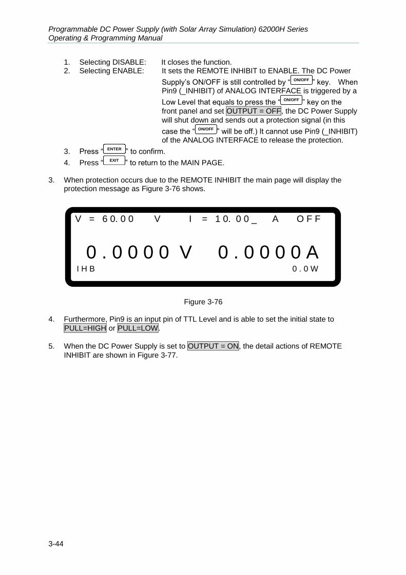
Programmable DC Power Supply (with Solar Array Simulation) 62000H Series Operating & Programming Manual
3-44
1. Selecting DISABLE: It closes the function. 2. Selecting ENABLE: It sets the REMOTE INHIBIT to ENABLE. The DC Power
Supply’s ON/OFF is still controlled by “ ON/OFF ” key. When Pin9 (_INHIBIT) of ANALOG INTERFACE is triggered by a
Low Level that equals to press the “ ON/OFF ” key on the
front panel and set OUTPUT = OFF, the DC Power Supply
will shut down and sends out a protection signal (in this
case the “ ON/OFF ” will be off.) It cannot use Pin9 (_INHIBIT) of the ANALOG INTERFACE to release the protection.
3. Press “ENTER
” to confirm.
4. Press “ EXIT ” to return to the MAIN PAGE. 3. When protection occurs due to the REMOTE INHIBIT the main page will display the
protection message as Figure 3-76 shows.
V = 6 0. 0 0 V I = 1 0. 0 0 _ A O F F
0 . 0 0 0 0 V 0 . 0 0 0 0 A I H B 0 . 0 W
Figure 3-76
4. Furthermore, Pin9 is an input pin of TTL Level and is able to set the initial state to
PULL=HIGH or PULL=LOW.
5. When the DC Power Supply is set to OUTPUT = ON, the detail actions of REMOTE
INHIBIT are shown in Figure 3-77.
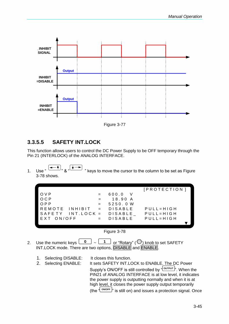
Manual Operation
3-45
_INHIBIT
SIGNAL
INHIBIT
=DISABLE
INHIBIT
=ENABLE
Output
Output
Figure 3-77
3.3.5.5 SAFETY INT.LOCK
This function allows users to control the DC Power Supply to be OFF temporary through the Pin 21 (INTERLOCK) of the ANALOG INTERFACE.
1. Use “ ” & “ ” keys to move the cursor to the column to be set as Figure 3-78 shows.
[ P R O T E C T I O N ]
O V P = 6 0 0 . 0 V
O C P = 1 8 . 9 0 A
O P P = 5 2 5 0 . 0 W
R E M O T E I N H I B I T = D I S A B L E P U L L = H I G H
S A F E T Y I N T . L O C K = D I S A B L E _ P U L L = H I G H
E X T O N / O F F = D I S A B L E P U L L = H I G H
▼
Figure 3-78
2. Use the numeric keys 0 ~ 1 or “Rotary” (
) knob to set SAFETY
INT.LOCK mode. There are two options, DISABLE and ENABLE.
1. Selecting DISABLE: It closes this function.
2. Selecting ENABLE: It sets SAFETY INT.LOCK to ENABLE. The DC Power
Supply’s ON/OFF is still controlled by “OUTPUT
”. When the PIN21 of ANALOG INTERFACE is at low level, it indicates the power supply is outputting normally and when it is at high level, it closes the power supply output temporarily
(the “ON/OFF
” is still on) and issues a protection signal. Once

Programmable DC Power Supply (with Solar Array Simulation) 62000H Series Operating & Programming Manual
3-46
Pin21 of the ANALOG INTERFACE is returned to low level, the DC Power Supply will continue to output normally.
3. Press “ENTER
” to confirm.
4. Press “ EXIT ” to return to the MAIN PAGE. 3. When protection occurs to SAFETY INT.LOCK the main page will display the protection
message as Figure 3-79 shows.
V = 6 0. 0 0 V I = 1 0. 0 0 _ A O F F
0 . 0 0 0 0 V 0 . 0 0 0 0 A S A F E T Y I N T E R L O C K 0 . 0 W
Figure 3-79
4. Furthermore, Pin21 is an input pin of TTL Level and is able to set the initial state to
PULL=HIGH or PULL=LOW.
5. When the DC Power Supply is set to OUTPUT = ON, the detail actions of SAFETY
INT.LOCK are as shown in Figure 3-84.
INTERLOCK
SIGNAL
INTERLOCK
=DISABLE
INTERLOCK
=ENABLE
Output
Output
Figure 3-80
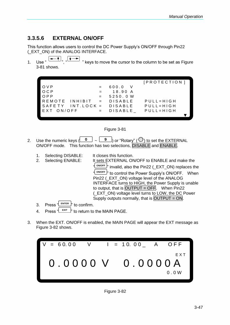
Manual Operation
3-47
3.3.5.6 EXTERNAL ON/OFF
This function allows users to control the DC Power Supply’s ON/OFF through Pin22 (_EXT_ON) of the ANALOG INTERFACE.
1. Use “ ”, “ ” keys to move the cursor to the column to be set as Figure 3-81 shows.
[ P R O T E C T I O N ]
O V P = 6 0 0 . 0 V
O C P = 1 8 . 9 0 A
O P P = 5 2 5 0 . 0 W
R E M O T E I N H I B I T = D I S A B L E P U L L = H I G H
S A F E T Y I N T . L O C K = D I S A B L E P U L L = H I G H
E X T O N / O F F = D I S A B L E _ P U L L = H I G H
▼
Figure 3-81
2. Use the numeric keys ( 0 ~ 9 ) or “Rotary” (
) to set the EXTERNAL
ON/OFF mode. This function has two selections, DISABLE and ENABLE.
1. Selecting DISABLE: It closes this function. 2. Selecting ENABLE: It sets EXTERNAL ON/OFF to ENABLE and make the
“ ON/OFF ” invalid, also the Pin22 (_EXT_ON) replaces the
“ ON/OFF ” to control the Power Supply’s ON/OFF. When Pin22 (_EXT_ON) voltage level of the ANALOG INTERFACE turns to HIGH, the Power Supply is unable
to output, that is OUTPUT = OFF. When Pin22
(_EXT_ON) voltage level turns to LOW, the DC Power
Supply outputs normally, that is OUTPUT = ON.
3. Press “ENTER
” to confirm.
4. Press “EXIT
” to return to the MAIN PAGE.
3. When the EXT. ON/OFF is enabled, the MAIN PAGE will appear the EXT message as
Figure 3-82 shows.
V = 6 0. 0 0 V I = 1 0. 0 0 _ A O F F
E X T
0 . 0 0 0 0 V 0 . 0 0 0 0 A 0 . 0 W
Figure 3-82

Programmable DC Power Supply (with Solar Array Simulation) 62000H Series Operating & Programming Manual
3-48
4. Furthermore, Pin22 is an input pin of TTL Level and is able to set the initial state to
PULL=HIGH or PULL=LOW.
5. When the DC Power Supply is set to OUTPUT = ON, the detail actions of EXTERNAL
ON/OFF are as shown in Figure 3-83.
_EXT ON
SIGNAL
EXT ON
=DISABLE
EXT ON
=ENABLE
Output
Output
Figure 3-83
3.3.5.7 FOLDBACK
This function allows users to turn off the output that is OUTPUT = OFF when changing
output mode (CV to CC or CC to CV) to protect the unit under test.
1. Use “ ”, “ ” keys to move the cursor to the column to be set as Figure 3-84 shows.
[ P R O T E C T I O N ]
F O L D B A C K = D I S A B L E
▲
Figure 3-84
2. Use the numeric keys ( 0 ~ 1 ) or “Rotary” (
) knob to set the FOLDBACK
mode. There are three options available for selection: DISABLE, CV TO CC and CC TO
CV.

Manual Operation
3-49
1. DISABLE: Ignore the output off function. 2. CV TO CC: Active in CV MODE only. Once the work mode changed to CC
MODE the system will turn off the output to protect the UUT. 3. CC TO CV: Active in CC MODE only. Once the work mode changed to CV
MODE the system will turn off the output to protect the UUT.
When the FOLDBACK option is set to CV TO CC or CC TO CV, a selection for DELAY
TIME will prompt beneath for the user to set the time delay for protection after the mode
has changed as Figure 3-85 shows.
[ P R O T E C T I O N ]
F O L D B A C K = C V T O C C_
D E L A Y T I M E = 0 . 0 1 S
Figure 3-85
When FOLDBACK protection occurs the main page will prompt a protection message as Figure 3-86 shows:
V = 6 0. 0 0 V I = 1 0. 0 0 _ A O F F
0 . 0 0 0 0 V 0 . 0 0 0 0 A C V T O C C F O L D B A C K 0 . 0 W
Figure 3-86
Be aware that if DELAY TIME sets to t seconds, it means the FOLDBACK that is set to CV TO CC or CC TO CV won’t be activated unless it sustains t seconds when a mode change is detected. If the change time of mode is less than t seconds it will return to its original state and FOLDBACK protection will not occur as Figure 3-87 shows.

Programmable DC Power Supply (with Solar Array Simulation) 62000H Series Operating & Programming Manual
3-50
DELAY TIME
CV MODE
CC MODE
Time
FOLDBACK
PROTECTION
DC SOURCE OPERATION MODE
Figure 3-87
Assuming the FOLDBACK is set to CV TO CC, the solid line in Figure 3-87 will create Foldback protection while the dotted line will not.
3. Press “ENTER
” to confirm.
4. Press “ EXIT ” to return to the MAIN PAGE.
3.3.5.8 OTP
The OTP protection will activate when the internal temperature reaches the high limit and the
output will be turned off that is OUTPUT = OFF for protection.
When OTP occurs the main page will prompt a protection message as Figure 3-88 shows:
V = 6 0. 0 0 V I = 1 0. 0 0 _ A O F F
0 . 0 0 0 0 V 0 . 0 0 0 0 A O T P 0 . 0 W
Figure 3-88
1. User is unable to change the OTP setting. 2. The output will turn off when OTP occurs and won’t be on again that
is OUTPUT = OFF until the internal temperature drops to a certain
set value.

Manual Operation
3-51
3.3.5.9 AC FAULT
The AC FAULT protection will activate when the internal input voltage is not within the model’s range, or when a certain input voltage is having an under voltage condition. The
output will turn off that is OUTPUT = OFF for protection.
When AC FAULT occurs the main page will prompt a protection message as Figure 3-89
shows:
V = 6 0. 0 0 V I = 1 0. 0 0 _ A O F F
0 . 0 0 0 0 V 0 . 0 0 0 0 A A C _ F A U L T 0 . 0 W
S H U T – D N
Figure 3-89
1. The table below lists the typical value of AC FAULT for 62000H
Series:
Table 3-5 AC FAULT Range
Line to Line Rated Voltage Lower than (Vac)
High than (Vac)
200/220Vac 180 242
380/400Vac 342 440
440/480Vac 396 528
200/240Vac 180 264
2. Once the AC FAULT is activated, the output is turned off that is
OUTPUT = OFF. Power off the device and then power it on again
after the input voltage spec and connection are confirmed. If any of the voltage specs or connection is incorrect, AC FAULT protection will occur continuously.
3. Be aware that the diameter of input wire cannot be too thin, or the line loss generated may cause the input voltage out of SPEC and AC FAULT may occur. See section 2.3.2 for the spec of wire diameter.
3.3.5.10 SENSE FAULT Protection
The remote sense is located at the rear panel near to output terminal. See section 2.4.1 for correct connection. When the connection is correct it can adjust the UUT’s voltage to be consistent with the panel set voltage without affecting by the voltage drop of load wire.
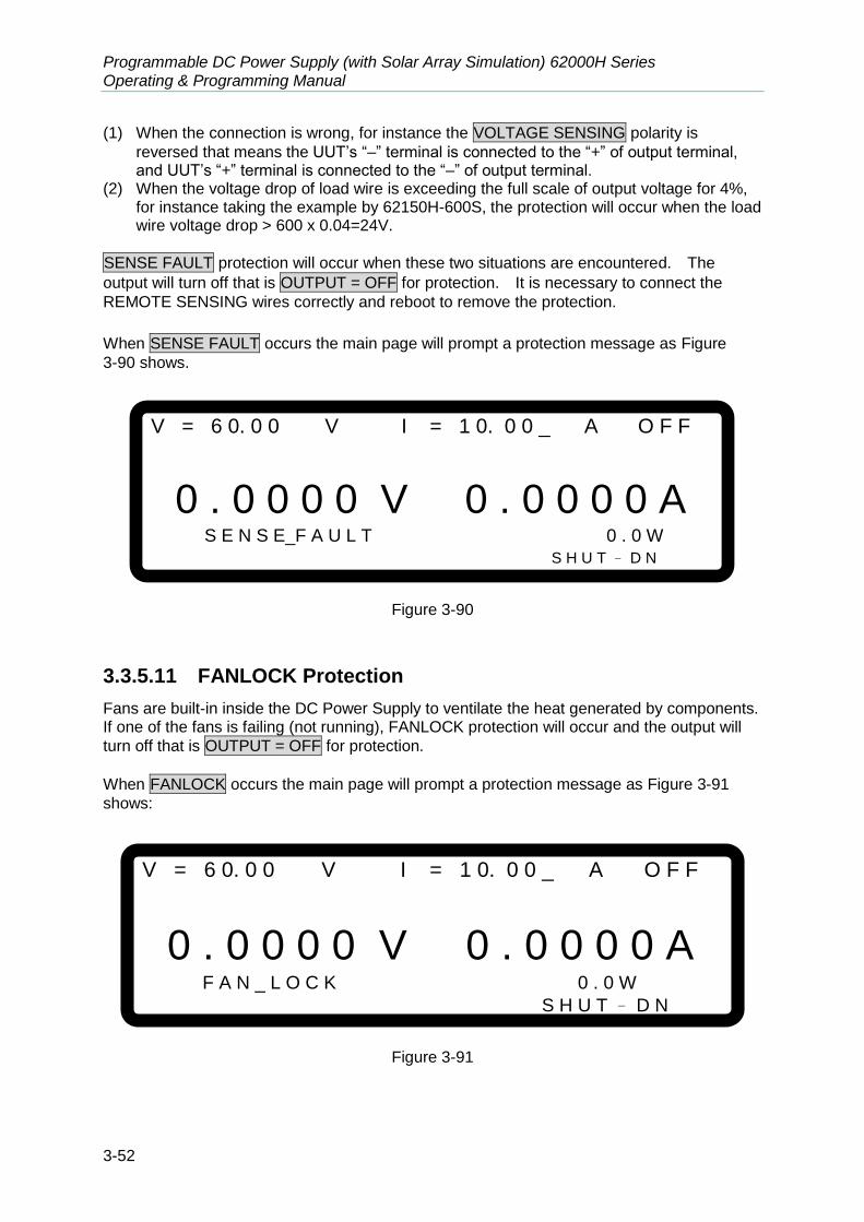
Programmable DC Power Supply (with Solar Array Simulation) 62000H Series Operating & Programming Manual
3-52
(1) When the connection is wrong, for instance the VOLTAGE SENSING polarity is
reversed that means the UUT’s “–” terminal is connected to the “+” of output terminal, and UUT’s “+” terminal is connected to the “–” of output terminal.
(2) When the voltage drop of load wire is exceeding the full scale of output voltage for 4%, for instance taking the example by 62150H-600S, the protection will occur when the load wire voltage drop > 600 x 0.04=24V.
SENSE FAULT protection will occur when these two situations are encountered. The
output will turn off that is OUTPUT = OFF for protection. It is necessary to connect the
REMOTE SENSING wires correctly and reboot to remove the protection.
When SENSE FAULT occurs the main page will prompt a protection message as Figure
3-90 shows.
V = 6 0. 0 0 V I = 1 0. 0 0 _ A O F F
0 . 0 0 0 0 V 0 . 0 0 0 0 A S E N S E_F A U L T 0 . 0 W
S H U T – D N
Figure 3-90
3.3.5.11 FANLOCK Protection
Fans are built-in inside the DC Power Supply to ventilate the heat generated by components. If one of the fans is failing (not running), FANLOCK protection will occur and the output will
turn off that is OUTPUT = OFF for protection.
When FANLOCK occurs the main page will prompt a protection message as Figure 3-91
shows:
V = 6 0. 0 0 V I = 1 0. 0 0 _ A O F F
0 . 0 0 0 0 V 0 . 0 0 0 0 A F A N _ L O C K 0 . 0 W
S H U T – D N
Figure 3-91
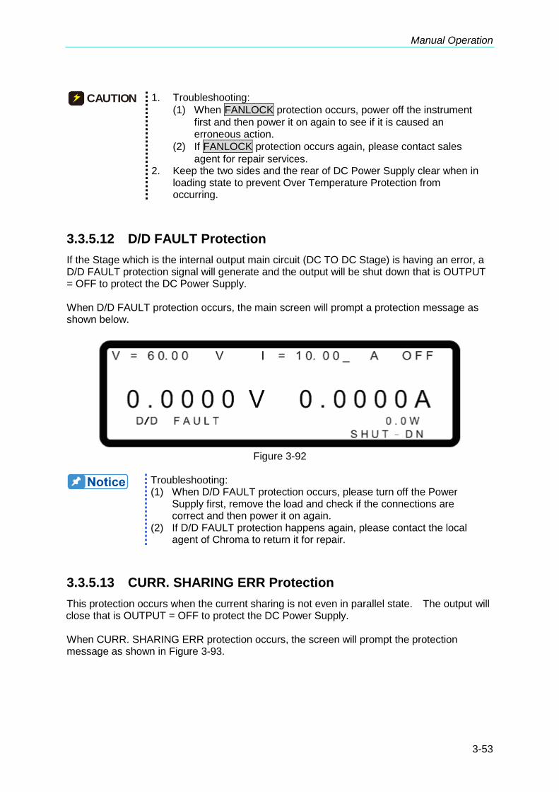
Manual Operation
3-53
CAUTION 1. Troubleshooting:
(1) When FANLOCK protection occurs, power off the instrument
first and then power it on again to see if it is caused an erroneous action.
(2) If FANLOCK protection occurs again, please contact sales
agent for repair services. 2. Keep the two sides and the rear of DC Power Supply clear when in
loading state to prevent Over Temperature Protection from occurring.
3.3.5.12 D/D FAULT Protection
If the Stage which is the internal output main circuit (DC TO DC Stage) is having an error, a D/D FAULT protection signal will generate and the output will be shut down that is OUTPUT = OFF to protect the DC Power Supply. When D/D FAULT protection occurs, the main screen will prompt a protection message as shown below.
Figure 3-92
Troubleshooting: (1) When D/D FAULT protection occurs, please turn off the Power
Supply first, remove the load and check if the connections are correct and then power it on again.
(2) If D/D FAULT protection happens again, please contact the local agent of Chroma to return it for repair.
3.3.5.13 CURR. SHARING ERR Protection
This protection occurs when the current sharing is not even in parallel state. The output will close that is OUTPUT = OFF to protect the DC Power Supply. When CURR. SHARING ERR protection occurs, the screen will prompt the protection message as shown in Figure 3-93.
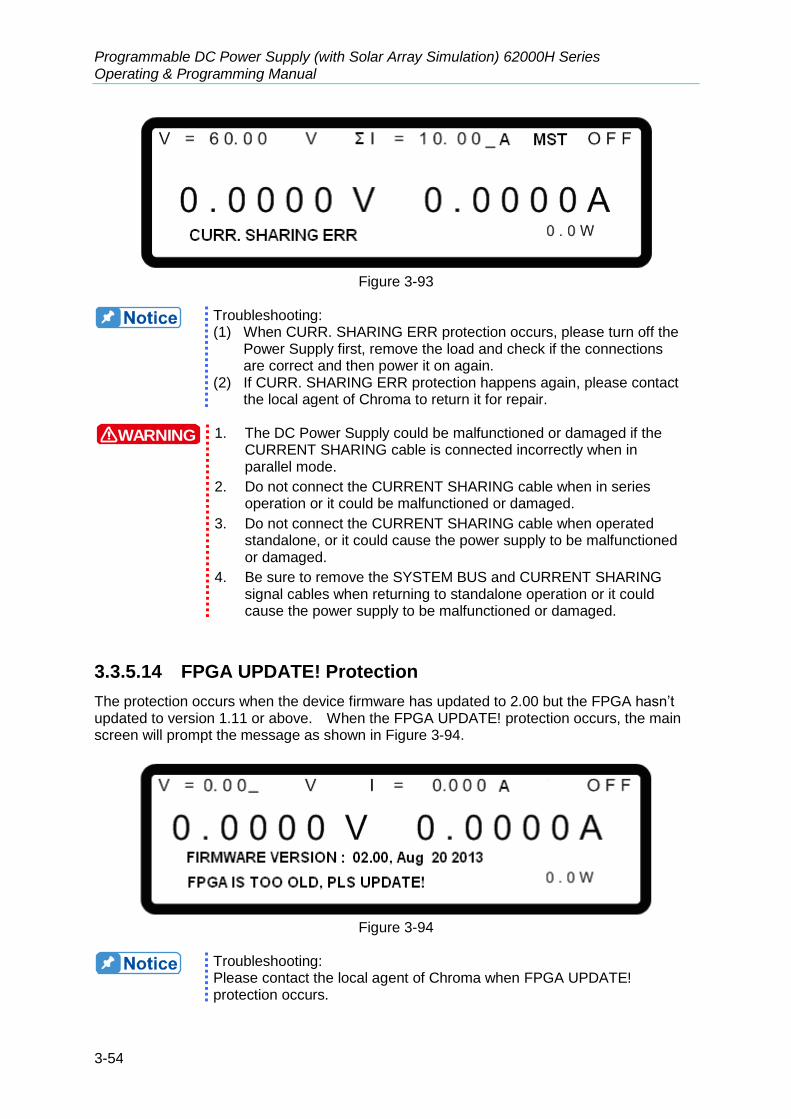
Programmable DC Power Supply (with Solar Array Simulation) 62000H Series Operating & Programming Manual
3-54
Figure 3-93
Troubleshooting: (1) When CURR. SHARING ERR protection occurs, please turn off the
Power Supply first, remove the load and check if the connections are correct and then power it on again.
(2) If CURR. SHARING ERR protection happens again, please contact the local agent of Chroma to return it for repair.
WARNING 1. The DC Power Supply could be malfunctioned or damaged if the
CURRENT SHARING cable is connected incorrectly when in parallel mode.
2. Do not connect the CURRENT SHARING cable when in series operation or it could be malfunctioned or damaged.
3. Do not connect the CURRENT SHARING cable when operated standalone, or it could cause the power supply to be malfunctioned or damaged.
4. Be sure to remove the SYSTEM BUS and CURRENT SHARING signal cables when returning to standalone operation or it could cause the power supply to be malfunctioned or damaged.
3.3.5.14 FPGA UPDATE! Protection
The protection occurs when the device firmware has updated to 2.00 but the FPGA hasn’t updated to version 1.11 or above. When the FPGA UPDATE! protection occurs, the main screen will prompt the message as shown in Figure 3-94.
Figure 3-94
Troubleshooting: Please contact the local agent of Chroma when FPGA UPDATE! protection occurs.

Manual Operation
3-55
3.3.5.15 C/S CABLE ERR. Protection
This protection occurs under the following three conditions. The first condition is when the DC Power Supply is in single unit mode and the rear panel connects the CURR. SHARING cable as Figure 3-95 shows. The second condition is when the DC Power Supply is in series mode and the CURR. SHARING cable is connected as shown in Figure 3-96 and Figure 3-97. The third condition is when the DC Power Supply is in parallel mode but the CURR. SHARING cable is not connected as shown in Figure 3-96 and Figure 3-97.
Figure 3-95
Figure 3-96
Figure 3-97
Troubleshooting: (1) When C/S CABLE ERR. protection occurs, please turn off the
Power Supply first, remove the load and check if the connections are correct and then power it on again.
(2) This protection only supports when the hardware is upgraded and the firmware version is 2.00 or above also the FPGA is 1.11 or above. Please check if there is HOOP mounting hole on the rear panel (the SLAVE models A620028 and A620027 are not included) as Figure 2-10 shows on the hardware to make sure it is an upgraded version.

Programmable DC Power Supply (with Solar Array Simulation) 62000H Series Operating & Programming Manual
3-56
(3) For hardware upgrade, please contact the agent of Chroma.
WARNING 1. The DC Power Supply could be malfunctioned or damaged if the
CURRENT SHARING cable is connected incorrectly when in parallel mode.
2. Do not connect the CURRENT SHARING cable when in series operation or it could be malfunctioned or damaged.
3. Do not connect the CURRENT SHARING cable when operated standalone, or it could cause the power supply to be malfunctioned or damaged.
4. Be sure to remove the SYSTEM BUS and CURRENT SHARING signal cables when returning to standalone operation or it could cause the power supply to be malfunctioned or damaged.
3.3.5.16 MATCH Warning
This warning occurs when using different models of DC Power Supply for parallel or series connections. When MATCH warning occurs, the main screen will prompt the message as shown in Figure 3-98.
Figure 3-98
Troubleshooting: (1) Please make sure the model numbers of the DC Power Supply for
parallel and series connection are the same. For instance, the 62050H-600S can only connect to the DC Power Supply of the same model no. for parallel or series connection. No other model numbers are applicable.
(2) The exceptions are the 62150H-1000S can connect with A620028 and the 62150H-600S can connect with A620027 for parallel/series connection.
It is NOT suggested to connect the power supplies with different input voltages for series or parallel use. The output specification cannot be guaranteed if the power supplies are not connected properly.
3.3.6 FACTORY SETTING
This function allows the user to reset the instrument to its factory default settings. To enter it:
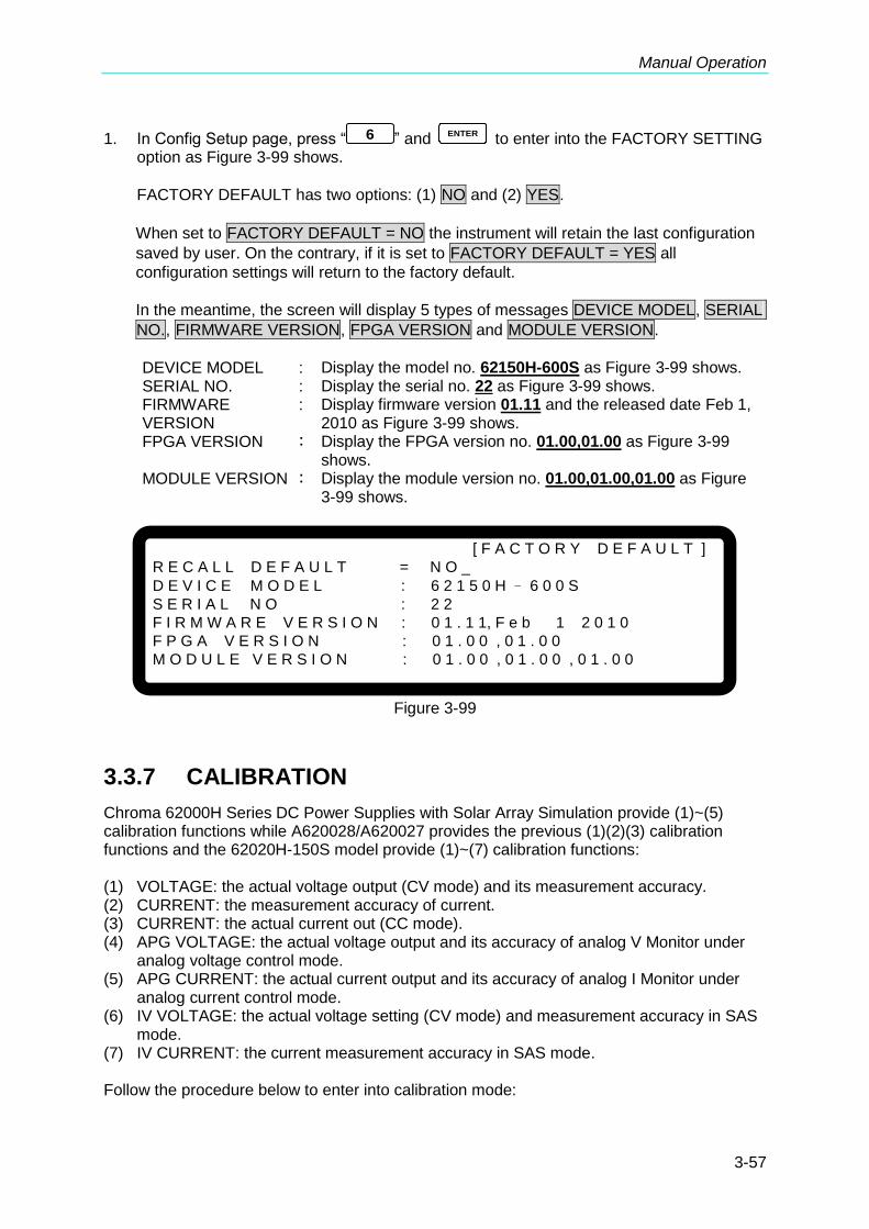
Manual Operation
3-57
1. In Config Setup page, press “ 6 ” and ENTER
to enter into the FACTORY SETTING option as Figure 3-99 shows.
FACTORY DEFAULT has two options: (1) NO and (2) YES.
When set to FACTORY DEFAULT = NO the instrument will retain the last configuration
saved by user. On the contrary, if it is set to FACTORY DEFAULT = YES all
configuration settings will return to the factory default.
In the meantime, the screen will display 5 types of messages DEVICE MODEL, SERIAL
NO., FIRMWARE VERSION, FPGA VERSION and MODULE VERSION.
DEVICE MODEL : Display the model no. 62150H-600S as Figure 3-99 shows. SERIAL NO. : Display the serial no. 22 as Figure 3-99 shows. FIRMWARE VERSION
: Display firmware version 01.11 and the released date Feb 1, 2010 as Figure 3-99 shows.
FPGA VERSION : Display the FPGA version no. 01.00,01.00 as Figure 3-99 shows.
MODULE VERSION : Display the module version no. 01.00,01.00,01.00 as Figure 3-99 shows.
[ F A C T O R Y D E F A U L T ]
R E C A L L D E F A U L T = N O _
D E V I C E M O D E L : 6 2 1 5 0 H – 6 0 0 S
S E R I A L N O : 2 2
F I R M W A R E V E R S I O N : 0 1 . 1 1, F e b 1 2 0 1 0
F P G A V E R S I O N : 0 1 . 0 0 , 0 1 . 0 0
M O D U L E V E R S I O N : 0 1 . 0 0 , 0 1 . 0 0 , 0 1 . 0 0
Figure 3-99
3.3.7 CALIBRATION
Chroma 62000H Series DC Power Supplies with Solar Array Simulation provide (1)~(5) calibration functions while A620028/A620027 provides the previous (1)(2)(3) calibration functions and the 62020H-150S model provide (1)~(7) calibration functions: (1) VOLTAGE: the actual voltage output (CV mode) and its measurement accuracy. (2) CURRENT: the measurement accuracy of current. (3) CURRENT: the actual current out (CC mode). (4) APG VOLTAGE: the actual voltage output and its accuracy of analog V Monitor under
analog voltage control mode. (5) APG CURRENT: the actual current output and its accuracy of analog I Monitor under
analog current control mode. (6) IV VOLTAGE: the actual voltage setting (CV mode) and measurement accuracy in SAS
mode. (7) IV CURRENT: the current measurement accuracy in SAS mode. Follow the procedure below to enter into calibration mode:
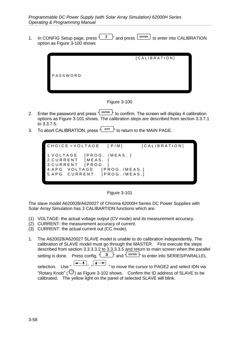
Programmable DC Power Supply (with Solar Array Simulation) 62000H Series Operating & Programming Manual
3-58
1. In CONFIG Setup page, press “ 7 ” and press ENTER
to enter into CALIBRATION option as Figure 3-100 shows
[ C A L I B R A T I O N ]
P A S S W O R D:
Figure 3-100
2. Enter the password and press “ENTER
” to confirm. The screen will display 4 calibration options as Figure 3-101 shows. The calibration steps are described from section 3.3.7.1 to 3.3.7.5.
3. To abort CALIBRATION, press “ EXIT ” to return to the MAIN PAGE.
C H O I C E = V O L T A G E [ P / M ] [ C A L I B R A T I O N ]
1. V O L T A G E [ P R O G . / M E A S . ]
2. C U R R E N T [ M E A S . ]
3. C U R R E N T [ P R O G . ]
4. A P G V O L T A G E [ P R O G . / M E A S . ]
5. A P G C U R R E N T [ P R O G . / M E A S . ]
Figure 3-101
The slave model A620028/A620027 of Chroma 62000H Series DC Power Supplies with Solar Array Simulation has 3 CALIBARTION functions which are: (1) VOLTAGE: the actual voltage output (CV mode) and its measurement accuracy. (2) CURRENT: the measurement accuracy of current. (3) CURRENT: the actual current out (CC mode). 1. The A620028/A620027 SLAVE model is unable to do calibration independently. The
calibration of SLAVE model must go through the MASTER. First execute the steps described from section 3.3.3.3.2 to 3.3.3.3.5 and return to main screen when the parallel
setting is done. Press config, “ 3 ” and “ENTER
” to enter into SERIES/PARALLEL
selection. Use “ ”, “ ” to move the cursor to PAGE2 and select IDN via
“Rotary Knob” (
) as Figure 3-102 shows. Confirm the ID address of SLAVE to be calibrated. The yellow light on the panel of selected SLAVE will blink.
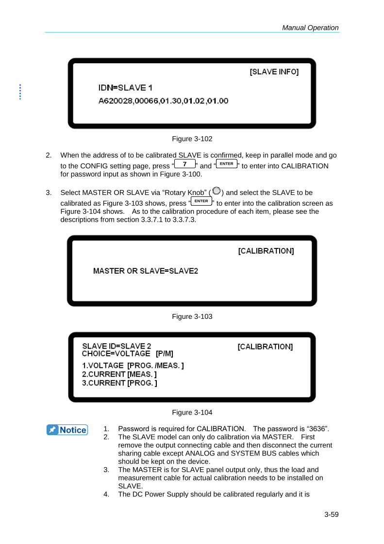
Manual Operation
3-59
Figure 3-102
2. When the address of to be calibrated SLAVE is confirmed, keep in parallel mode and go
to the CONFIG setting page, press “ 7 ” and “ENTER
” to enter into CALIBRATION for password input as shown in Figure 3-100.
3. Select MASTER OR SLAVE via “Rotary Knob” (
) and select the SLAVE to be
calibrated as Figure 3-103 shows, press “ENTER
” to enter into the calibration screen as Figure 3-104 shows. As to the calibration procedure of each item, please see the descriptions from section 3.3.7.1 to 3.3.7.3.
Figure 3-103
Figure 3-104
1. Password is required for CALIBRATION. The password is “3636”. 2. The SLAVE model can only do calibration via MASTER. First
remove the output connecting cable and then disconnect the current sharing cable except ANALOG and SYSTEM BUS cables which should be kept on the device.
3. The MASTER is for SLAVE panel output only, thus the load and measurement cable for actual calibration needs to be installed on SLAVE.
4. The DC Power Supply should be calibrated regularly and it is

Programmable DC Power Supply (with Solar Array Simulation) 62000H Series Operating & Programming Manual
3-60
suggested to do the calibration once every other year. For further requirements, please contact Chroma to arrange for calibration again.
3.3.7.1 Voltage Output & Measurement Calibration
3.3.7.1.1 Hardware Requirement
The hardware requirement is shown in Table 3-6.
Table 3-6
Device Suggested Model or Capacity
DVM HP 34401A or equivalent DVM
3.3.7.1.2 SETUP
The setup is shown in Figure 3-105.
62000H
DC Power Supply
v
v
DVM
sv
sv
Figure 3-105
1. For the instrument that performs calibration its accuracy has to be
higher than the accuracy of spec. 2. It is suggested to set the Resolution parameter of HP34401 to
SLOW 6 digit. 3. When conducting the voltage calibration, each calibration point has
to key in at least 5 Arabic numerals to ensure the Power Supply accuracy after calibration.
3.3.7.1.3 Calibration Procedure (Example: Model 62150H-600S)
1. Enter into the page of Figure 3-101.
2. In CALIBRATION page, press “ 1 ” or turn “Rotary” (
) knob to set CHOICE=1.
3. Press “ENTER
” to confirm entering into voltage calibration options as Figure 3-106 shows.
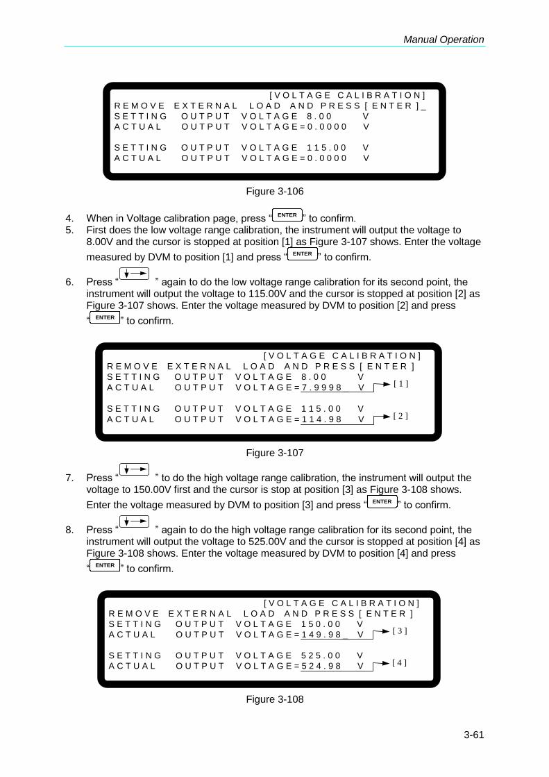
Manual Operation
3-61
[ V O L T A G E C A L I B R A T I O N ]
R E M O V E E X T E R N A L L O A D A N D P R E S S [ E N T E R ] _
S E T T I N G O U T P U T V O L T A G E 8 . 0 0 V
A C T U A L O U T P U T V O L T A G E = 0 . 0 0 0 0 V
S E T T I N G O U T P U T V O L T A G E 1 1 5 . 0 0 V
A C T U A L O U T P U T V O L T A G E = 0 . 0 0 0 0 V
Figure 3-106
4. When in Voltage calibration page, press “ENTER
” to confirm. 5. First does the low voltage range calibration, the instrument will output the voltage to
8.00V and the cursor is stopped at position [1] as Figure 3-107 shows. Enter the voltage
measured by DVM to position [1] and press “ENTER
” to confirm.
6. Press “ ” again to do the low voltage range calibration for its second point, the instrument will output the voltage to 115.00V and the cursor is stopped at position [2] as Figure 3-107 shows. Enter the voltage measured by DVM to position [2] and press
“ENTER
” to confirm.
[ V O L T A G E C A L I B R A T I O N ]
R E M O V E E X T E R N A L L O A D A N D P R E S S [ E N T E R ]
S E T T I N G O U T P U T V O L T A G E 8 . 0 0 V
A C T U A L O U T P U T V O L T A G E = 7 . 9 9 9 8 _ V
S E T T I N G O U T P U T V O L T A G E 1 1 5 . 0 0 V
A C T U A L O U T P U T V O L T A G E = 1 1 4 . 9 8 V
[ 1 ]
[ 2 ]
Figure 3-107
7. Press “ ” to do the high voltage range calibration, the instrument will output the voltage to 150.00V first and the cursor is stop at position [3] as Figure 3-108 shows.
Enter the voltage measured by DVM to position [3] and press “ENTER
” to confirm.
8. Press “ ” again to do the high voltage range calibration for its second point, the instrument will output the voltage to 525.00V and the cursor is stopped at position [4] as Figure 3-108 shows. Enter the voltage measured by DVM to position [4] and press
“ENTER
” to confirm.
[ V O L T A G E C A L I B R A T I O N ]
R E M O V E E X T E R N A L L O A D A N D P R E S S [ E N T E R ]
S E T T I N G O U T P U T V O L T A G E 1 5 0 . 0 0 V
A C T U A L O U T P U T V O L T A G E = 1 4 9 . 9 8 _ V
S E T T I N G O U T P U T V O L T A G E 5 2 5 . 0 0 V
A C T U A L O U T P U T V O L T A G E = 5 2 4 . 9 8 V
[ 3 ]
[ 4 ]
Figure 3-108

Programmable DC Power Supply (with Solar Array Simulation) 62000H Series Operating & Programming Manual
3-62
9. Now the voltage calibration is done. To save the calibration data, press “ SAVE ” will
prompt a confirmation page as Figure 3-109 shows. Press “ 1 ” or “Rotary” (
) to
set SAVE=YES and press “ENTER
” to save it. If there is no need to save it, press
“ EXIT ” to return to the Calibration screen.
[ S A V E A R G U M E N T ]
S A V E = N O
Figure 3-109
10. Press “ EXIT ” to return to the MAIN PAGE.
1. The calibration point may be different for other models (non
62150H-600S), please operate it following the instructions displayed.
2. It is necessary to remove the output load when performing voltage calibration. The LCD panel will show the text as Figure 3-107 and
once no load is confirmed for the output, press “ENTER
” to start calibration.
3.3.7.2 Current Measurement Calibration
3.3.7.2.1 Hardware Requirements
Table 3-7 lists the hardware requirements for current measurement calibration.
Table 3-7
Device Suggest Model or Capacity
DVM HP 34401A or equivalent DVM
CURRENT SHUNT Prodigit 7550 or ULTRASTAB SATURN or equivalent
LOAD ELECTRICAL LOAD CHROMA 63204 or equivalent
BREAKER Capable current>=100A
CAUTION 1. The table above lists the BREAKER capacity for 62150H-600S only.
The applicable BREAKER for other models, please see the specifications of OUTPUT CURRENT in Table 1-1.
2. The model 62020H-150S needs to use ULTRASTAB SATURN to do the calibration.

Manual Operation
3-63
3.3.7.2.2 SETUP
Figure 3-110 is the diagram for connecting current calibration devices.
62000H
DC Power Supply
v
v
DVM
sv
sv
Current Shunt
Electronic Load
Breaker
Figure 3-110
1. Before using ULTRASTAB SATURN for current calibration, it needs
to calibrate the offset voltage of ULTRASTAB SATURN first. Press
“Null
” and the DVM panel digits will reset and show “Math” for current calibration.
2. When conducting the current calibration, each calibration point has to key in at least 5 Arabic numerals to ensure the Power Supply accuracy after calibration.
3.3.7.2.3 Calibration Procedure (Example: Model 62150H-600S)
1. Enter into the page of Figure 3-101.
2. In CALIBRATION page, press “ 2 ” or turn “Rotary” (
) knob to set CHOICE=2.
3. Press “ENTER
” to confirm and entering into current calibration options as Figure 3-111 shows.
[ C U R R E N T M E A S C A L I B R A T I O N ]
R E M O V E A L L L O A D I N G F R O M O U T P U T T E R M I N A L
P R E S S [ E N T E R ] W H E N R E A D Y
Figure 3-111
4. Open the Breaker to ensure the DC Power Supply has no load and press “ENTER
” to confirm.
5. It is important to reconnect the DC Power Supply to current shunt whose rating is closest to but still cover 2A. For Prodigit 7550, use 2A shunt directly.
6. Then it will show Figure 3-112 and press “ENTER
”. First it will calibrate the low current range, the system outputs a fixed voltage and then sets the loading current of Electronic LOAD to 1.5A. The cursor is stopped at position [1] as Figure 3-112 shows. Enter the
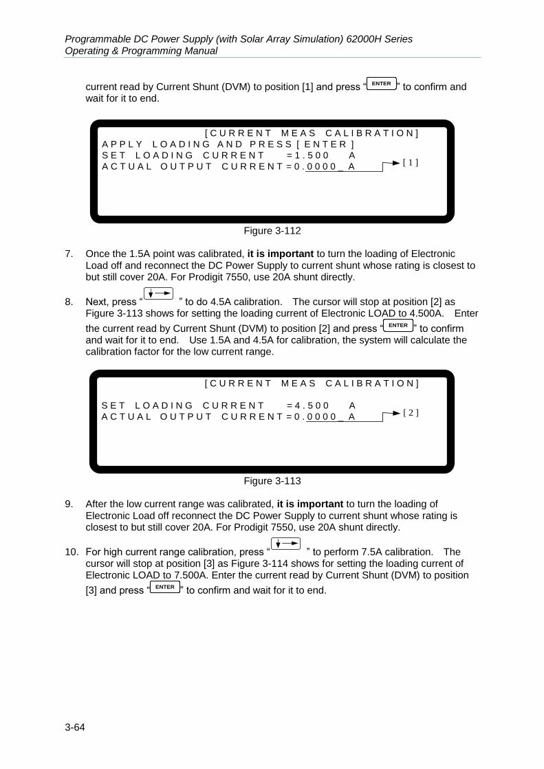
Programmable DC Power Supply (with Solar Array Simulation) 62000H Series Operating & Programming Manual
3-64
current read by Current Shunt (DVM) to position [1] and press “ENTER
” to confirm and wait for it to end.
[ C U R R E N T M E A S C A L I B R A T I O N ]
A P P L Y L O A D I N G A N D P R E S S [ E N T E R ]
S E T L O A D I N G C U R R E N T = 1 . 5 0 0 A
A C T U A L O U T P U T C U R R E N T = 0 . 0 0 0 0 _ A
[ 1 ]
Figure 3-112
7. Once the 1.5A point was calibrated, it is important to turn the loading of Electronic
Load off and reconnect the DC Power Supply to current shunt whose rating is closest to but still cover 20A. For Prodigit 7550, use 20A shunt directly.
8. Next, press “ ” to do 4.5A calibration. The cursor will stop at position [2] as Figure 3-113 shows for setting the loading current of Electronic LOAD to 4.500A. Enter
the current read by Current Shunt (DVM) to position [2] and press “ENTER
” to confirm and wait for it to end. Use 1.5A and 4.5A for calibration, the system will calculate the calibration factor for the low current range.
[ C U R R E N T M E A S C A L I B R A T I O N ]
S E T L O A D I N G C U R R E N T = 4 . 5 0 0 A
A C T U A L O U T P U T C U R R E N T = 0 . 0 0 0 0 _ A
[ 2 ]
Figure 3-113
9. After the low current range was calibrated, it is important to turn the loading of
Electronic Load off reconnect the DC Power Supply to current shunt whose rating is closest to but still cover 20A. For Prodigit 7550, use 20A shunt directly.
10. For high current range calibration, press “ ” to perform 7.5A calibration. The cursor will stop at position [3] as Figure 3-114 shows for setting the loading current of Electronic LOAD to 7.500A. Enter the current read by Current Shunt (DVM) to position
[3] and press “ENTER
” to confirm and wait for it to end.

Manual Operation
3-65
[ C U R R E N T M E A S C A L I B R A T I O N ]
S E T L O A D I N G C U R R E N T = 7 . 5 0 0 A
A C T U A L O U T P U T C U R R E N T = 0 . 0 0 0 0 _ A
[ 3 ]
Figure 3-114
11. Once the 7.5A point was calibrated, it is important to turn the loading of Electronic
Load off reconnect the DC Power Supply to current shunt whose rating is closest to but still cover 20A. For Prodigit 7550, use 20A shunt directly.
12. Press “ ” to perform 19.5A calibration. The cursor will stop at position [4] as Figure 3-115 shows for setting the loading current of Electronic LOAD to 19.500A. Enter
the current read by Current Shunt (DVM) to position [4] and press “ENTER
” to confirm and wait for it to end. Use 7.5A and 19.5A for calibration, the system will calculate the calibration factor for the high current range.
[ C U R R E N T M E A S C A L I B R A T I O N ]
S E T L O A D I N G C U R R E N T = 1 9 . 5 0 0 A
A C T U A L O U T P U T C U R R E N T = 0 . 0 0 0 0 _ A
[ 4 ]
Figure 3-115
13. The current calibration is done once the above actions are completed. To save the
calibration data, press “ SAVE ” will prompt a confirmation page as Figure 3-116 shows.
Press “ 1 ” or “Rotary” (
) to set SAVE=YES and press “ENTER
” to save it. If
there is no need to save it, press “EXIT
” to return to the Calibration screen.
[ S A V E A R G U M E N T ]
S A V E = N O
Figure 3-116
14. Press “EXIT
” to return to the MAIN PAGE.
WARNING Improper shunt range selection may cause damage to the current shunt.

Programmable DC Power Supply (with Solar Array Simulation) 62000H Series Operating & Programming Manual
3-66
The calibration point may be different for other models (non 62150H-600S), please operate it following the instructions displayed.
3.3.7.3 Current Output (PROG.) Calibration
3.3.7.3.1 Hardware Requirements
Table 3-8 lists the hardware requirements for current output calibration.
Table 3-8
Device Suggest Model or Capacity
DVM HP 34401A or equivalent DVM
CURRENT SHUNT Prodigit 7550 or ULTRASTAB SATURN or equivalent
LOAD ELECTRICAL LOAD CHROMA 63204 or equivalent
BREAKER Capable current>=100A
CAUTION 1. The table above lists the BREAKER capacity for 62150H-600S only.
The applicable BREAKER for other models, please see the specifications of OUTPUT CURRENT in Table 1-1.
2. The Model 62020H-150S needs to use ULTRASTAB SATURN to do the calibration.
3.3.7.3.2 SETUP
Figure 3-117 shows the wire connection.
62000H
DC Power Supply
v
v
DVM
sv
sv
Current Shunt
Electronic Load
Breaker
Figure 3-117
1. Before using ULTRASTAB SATURN for current calibration, it needs
to calibrate the offset voltage of ULTRASTAB SATURN first. Press
“Null
” and the DVM panel digits will reset and show “Math” for current calibration.
2. When conducting the current calibration, each calibration point has to key in at least 5 Arabic numerals to ensure the Power Supply accuracy after calibration.
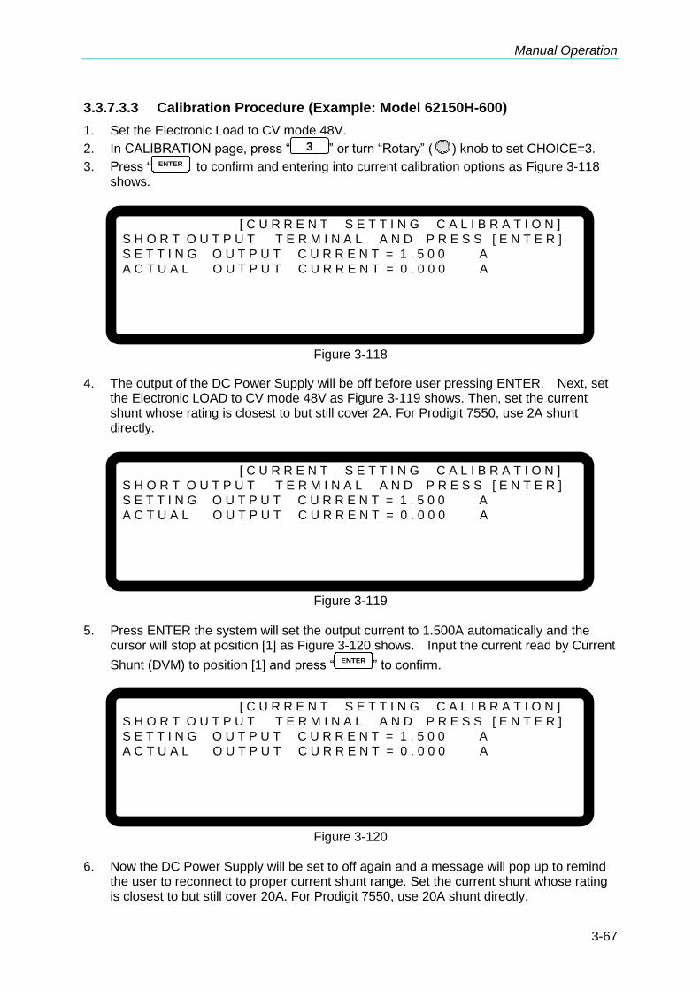
Manual Operation
3-67
3.3.7.3.3 Calibration Procedure (Example: Model 62150H-600)
1. Set the Electronic Load to CV mode 48V. 2. In CALIBRATION page, press “ 3 ” or turn “Rotary” (
) knob to set CHOICE=3.
3. Press “ ENTER to confirm and entering into current calibration options as Figure 3-118 shows.
[ C U R R E N T S E T T I N G C A L I B R A T I O N ]
S H O R T O U T P U T T E R M I N A L A N D P R E S S [ E N T E R ]
S E T T I N G O U T P U T C U R R E N T = 1 . 5 0 0 A
A C T U A L O U T P U T C U R R E N T = 0 . 0 0 0 A
Figure 3-118
4. The output of the DC Power Supply will be off before user pressing ENTER. Next, set
the Electronic LOAD to CV mode 48V as Figure 3-119 shows. Then, set the current shunt whose rating is closest to but still cover 2A. For Prodigit 7550, use 2A shunt directly.
[ C U R R E N T S E T T I N G C A L I B R A T I O N ]
S H O R T O U T P U T T E R M I N A L A N D P R E S S [ E N T E R ]
S E T T I N G O U T P U T C U R R E N T = 1 . 5 0 0 A
A C T U A L O U T P U T C U R R E N T = 0 . 0 0 0 A
Figure 3-119
5. Press ENTER the system will set the output current to 1.500A automatically and the
cursor will stop at position [1] as Figure 3-120 shows. Input the current read by Current
Shunt (DVM) to position [1] and press “ENTER
” to confirm.
[ C U R R E N T S E T T I N G C A L I B R A T I O N ]
S H O R T O U T P U T T E R M I N A L A N D P R E S S [ E N T E R ]
S E T T I N G O U T P U T C U R R E N T = 1 . 5 0 0 A
A C T U A L O U T P U T C U R R E N T = 0 . 0 0 0 A
Figure 3-120
6. Now the DC Power Supply will be set to off again and a message will pop up to remind
the user to reconnect to proper current shunt range. Set the current shunt whose rating is closest to but still cover 20A. For Prodigit 7550, use 20A shunt directly.

Programmable DC Power Supply (with Solar Array Simulation) 62000H Series Operating & Programming Manual
3-68
7. Press “ ” will perform 4.5A calibration. The system will set the output current to 4.500A automatically and the cursor will stop at position [2] as Figure 3-121 shows.
Input the current read by Current Shunt (DVM) to position [2] and press “ENTER
” to confirm. Use 1.5A and 4.5A for calibration, the system will calculate the calibration factor for the low current range.
[ C U R R E N T S E T T I N G C A L I B R A T I O N ]
S E T T I N G O U T P U T C U R R E N T = 4 . 5 0 0 A
A C T U A L O U T P U T C U R R E N T = 0 . 0 0 0 _ A
[ 2 ]
Figure 3-121
8. Now start the high current range calibration. Set the current shunt whose rating is
closest to but still cover 20A. For Prodigit 7550, use 20A shunt directly.
9. Press “ ” will perform 7.5A calibration. The system will set the output current to 7.500A automatically and the cursor will stop at position [3] as Figure 3-122 shows.
Input the current read by Current Shunt (DVM) to position [3] and press “ENTER
” to confirm.
[ C U R R E N T S E T T I N G C A L I B R A T I O N ]
S E T T I N G O U T P U T C U R R E N T = 7 . 5 0 0 A
A C T U A L O U T P U T C U R R E N T = 0 . 0 0 0 _ A
[ 3 ]
Figure 3-122
10. The DC Power Supply will be set to off again. Set the current shunt whose rating is
closest to but still cover 20A. For Prodigit 7550, use 20A shunt directly.
11. Press “ ” will perform 19.5A calibration. The system will set the output current to 19.500A automatically and the cursor will stop at position [4] as Figure 3-123 shows.
Input the current read by Current Shunt (DVM) to position [4] and press “ENTER
” to confirm.
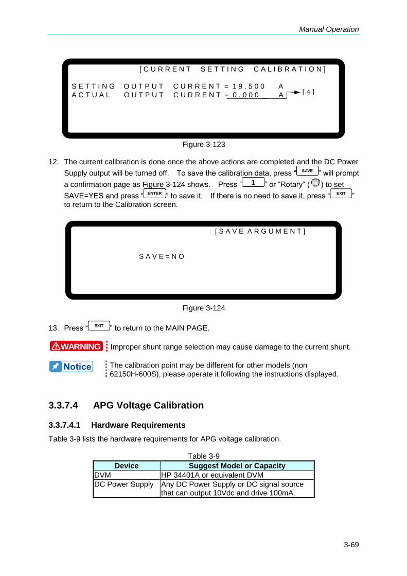
Manual Operation
3-69
[ C U R R E N T S E T T I N G C A L I B R A T I O N ]
S E T T I N G O U T P U T C U R R E N T = 1 9 . 5 0 0 A
A C T U A L O U T P U T C U R R E N T = 0 . 0 0 0 _ A
[ 4 ]
Figure 3-123
12. The current calibration is done once the above actions are completed and the DC Power
Supply output will be turned off. To save the calibration data, press “ SAVE ” will prompt
a confirmation page as Figure 3-124 shows. Press “ 1 ” or “Rotary” (
) to set
SAVE=YES and press “ENTER
” to save it. If there is no need to save it, press “ EXIT ” to return to the Calibration screen.
[ S A V E A R G U M E N T ]
S A V E = N O
Figure 3-124
13. Press “ EXIT ” to return to the MAIN PAGE.
WARNING Improper shunt range selection may cause damage to the current shunt.
The calibration point may be different for other models (non 62150H-600S), please operate it following the instructions displayed.
3.3.7.4 APG Voltage Calibration
3.3.7.4.1 Hardware Requirements
Table 3-9 lists the hardware requirements for APG voltage calibration.
Table 3-9
Device Suggest Model or Capacity
DVM HP 34401A or equivalent DVM
DC Power Supply Any DC Power Supply or DC signal source that can output 10Vdc and drive 100mA.
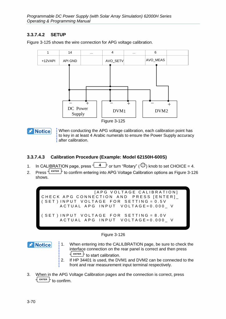
Programmable DC Power Supply (with Solar Array Simulation) 62000H Series Operating & Programming Manual
3-70
3.3.7.4.2 SETUP
Figure 3-125 shows the wire connection for APG voltage calibration.
DC Power
SupplyDVM1 DVM2
1
+12VAPI API GND AVO_SETV
14 ... 4 ... 6
AVO_MEAS
Figure 3-125
When conducting the APG voltage calibration, each calibration point has to key in at least 4 Arabic numerals to ensure the Power Supply accuracy after calibration.
3.3.7.4.3 Calibration Procedure (Example: Model 62150H-600S)
1. In CALIBRATION page, press “ 4 ” or turn “Rotary” (
) knob to set CHOICE = 4.
2. Press “ENTER
” to confirm entering into APG Voltage Calibration options as Figure 3-126 shows.
[ A P G V O L T A G E C A L I B R A T I O N ]
C H E C K A P G C O N N E C T I O N A N D P R E S S [ E N T E R ] _
( S E T ) I N P U T V O L T A G E F O R S E T T I N G = 0 . 5 V
A C T U A L A P G I N P U T V O L T A G E = 0 . 0 0 0 _ V
( S E T ) I N P U T V O L T A G E F O R S E T T I N G = 8 . 0 V
A C T U A L A P G I N P U T V O L T A G E = 0 . 0 0 0 _ V
Figure 3-126
1. When entering into the CALILBRATION page, be sure to check the
interface connection on the rear panel is correct and then press
“ENTER
” to start calibration. 2. If HP 34401 is used, the DVM1 and DVM2 can be connected to the
front and rear measurement input terminal respectively. 3. When in the APG Voltage Calibration pages and the connection is correct, press
“ENTER
” to confirm.
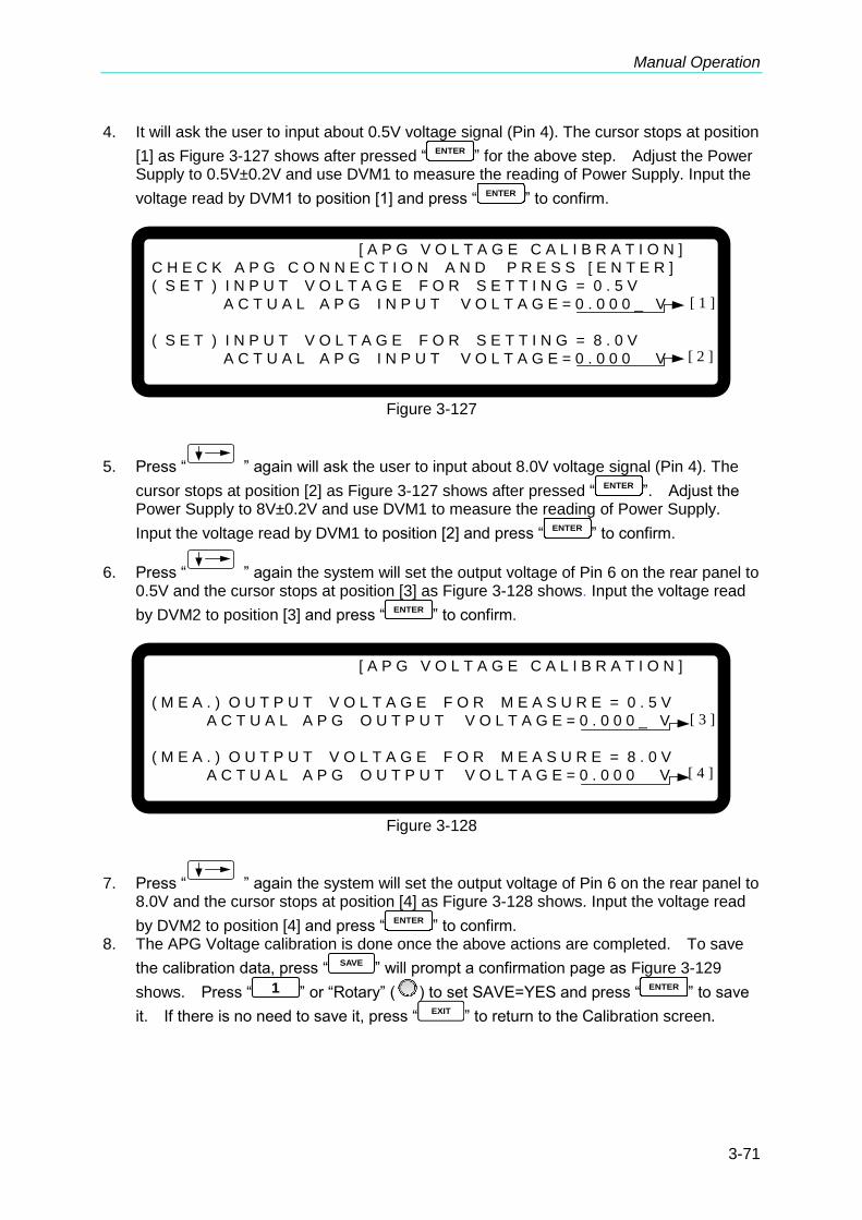
Manual Operation
3-71
4. It will ask the user to input about 0.5V voltage signal (Pin 4). The cursor stops at position
[1] as Figure 3-127 shows after pressed “ENTER
” for the above step. Adjust the Power Supply to 0.5V±0.2V and use DVM1 to measure the reading of Power Supply. Input the
voltage read by DVM1 to position [1] and press “ENTER
” to confirm.
[ A P G V O L T A G E C A L I B R A T I O N ]
C H E C K A P G C O N N E C T I O N A N D P R E S S [ E N T E R ]
( S E T ) I N P U T V O L T A G E F O R S E T T I N G = 0 . 5 V
A C T U A L A P G I N P U T V O L T A G E = 0 . 0 0 0 _ V
( S E T ) I N P U T V O L T A G E F O R S E T T I N G = 8 . 0 V
A C T U A L A P G I N P U T V O L T A G E = 0 . 0 0 0 V
[ 1 ]
[ 2 ]
Figure 3-127
5. Press “ ” again will ask the user to input about 8.0V voltage signal (Pin 4). The
cursor stops at position [2] as Figure 3-127 shows after pressed “ENTER
”. Adjust the Power Supply to 8V±0.2V and use DVM1 to measure the reading of Power Supply.
Input the voltage read by DVM1 to position [2] and press “ENTER
” to confirm.
6. Press “ ” again the system will set the output voltage of Pin 6 on the rear panel to 0.5V and the cursor stops at position [3] as Figure 3-128 shows. Input the voltage read
by DVM2 to position [3] and press “ENTER
” to confirm.
[ A P G V O L T A G E C A L I B R A T I O N ]
( M E A . ) O U T P U T V O L T A G E F O R M E A S U R E = 0 . 5 V
A C T U A L A P G O U T P U T V O L T A G E = 0 . 0 0 0 _ V
( M E A . ) O U T P U T V O L T A G E F O R M E A S U R E = 8 . 0 V
A C T U A L A P G O U T P U T V O L T A G E = 0 . 0 0 0 V
[ 3 ]
[ 4 ]
Figure 3-128
7. Press “ ” again the system will set the output voltage of Pin 6 on the rear panel to 8.0V and the cursor stops at position [4] as Figure 3-128 shows. Input the voltage read
by DVM2 to position [4] and press “ENTER
” to confirm. 8. The APG Voltage calibration is done once the above actions are completed. To save
the calibration data, press “SAVE
” will prompt a confirmation page as Figure 3-129
shows. Press “ 1 ” or “Rotary” (
) to set SAVE=YES and press “ENTER
” to save
it. If there is no need to save it, press “EXIT
” to return to the Calibration screen.
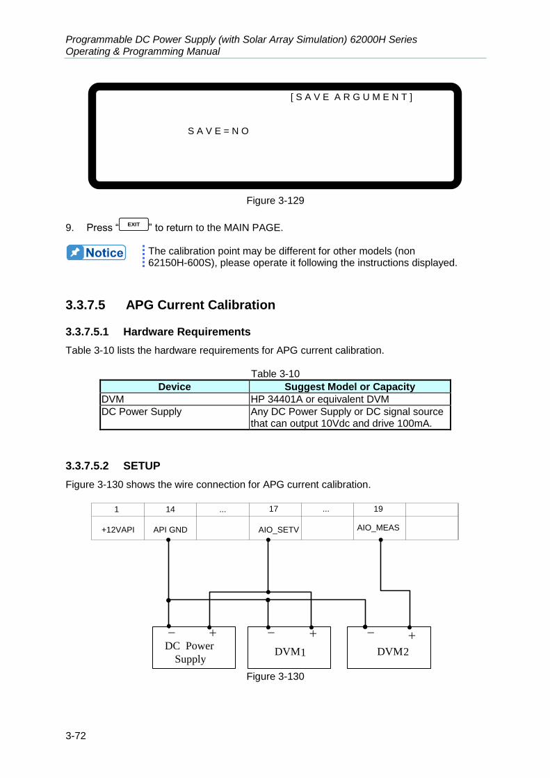
Programmable DC Power Supply (with Solar Array Simulation) 62000H Series Operating & Programming Manual
3-72
[ S A V E A R G U M E N T ]
S A V E = N O
Figure 3-129
9. Press “ EXIT ” to return to the MAIN PAGE.
The calibration point may be different for other models (non 62150H-600S), please operate it following the instructions displayed.
3.3.7.5 APG Current Calibration
3.3.7.5.1 Hardware Requirements
Table 3-10 lists the hardware requirements for APG current calibration.
Table 3-10
Device Suggest Model or Capacity
DVM HP 34401A or equivalent DVM
DC Power Supply Any DC Power Supply or DC signal source that can output 10Vdc and drive 100mA.
3.3.7.5.2 SETUP
Figure 3-130 shows the wire connection for APG current calibration.
DC Power
SupplyDVM1 DVM2
1
+12VAPI API GND AIO_SETV
14 ... 17 ... 19
AIO_MEAS
Figure 3-130

Manual Operation
3-73
When conducting the APG current calibration, each calibration point has to key in at least 4 Arabic numerals to ensure the Power Supply accuracy after calibration.
3.3.7.5.3 Calibration Procedure (Example: Model 62150H-600S)
1. In CALIBRATION page, press “ 5 ” or turn the “Rotary” (
) knob to set CHOICE = 5.
2. Press “ENTER
” to confirm entering into APG Voltage Calibration options as Figure 3-131 shows.
[ A P G C U R R E N T C A L I B R A T I O N ]
C H E C K A P G C O N N E C T I O N A N D P R E S S [ E N T E R ] _
( S E T ) I N P U T V O L T A G E F O R S E T T I N G = 0 . 5 V
A C T U A L A P G I N P U T V O L T A G E = 0 . 0 0 0 V
( S E T ) I N P U T V O L T A G E F O R S E T T I N G = 8 . 0 V
A C T U A L A P G I N P U T V O L T A G E = 0 . 0 0 0 V
Figure 3-131
When entering into the CALILBRATION page, be sure to check the
interface connection on the rear panel is correct and then press “ENTER
” to start calibration.
3. When in the APG Current Calibration pages and the connection is correct, press
“ENTER
” to confirm. 4. It will ask the user to input about 0.5V voltage signal (Pin 17). The cursor stops at
position [1] as Figure 3-132 shows after pressed “ENTER
” in the above step. Adjust the Power Supply to 0.5V±0.2V and use DVM1 to measure the reading of Power Supply.
Input the voltage read by DVM 1 to position [1] and press “ENTER
” to confirm.
[ A P G C U R R E N T C A L I B R A T I O N ]
C H E C K A P G C O N N E C T I O N A N D P R E S S [ E N T E R ]
( S E T ) I N P U T V O L T A G E F O R S E T T I N G = 0 . 5 V
A C T U A L A P G I N P U T V O L T A G E = 0 . 0 0 0 _ V
( S E T ) I N P U T V O L T A G E F O R S E T T I N G = 8 . 0 V
A C T U A L A P G I N P U T V O L T A G E = 0 . 0 0 0 V
[ 1 ]
[ 2 ]
Figure 3-132
5. Press “ ” again will ask the user to input about 8.0V voltage signal (Pin 17). The
cursor stops at position [2] as Figure 3-132 shows after pressed “ENTER
” in the above step. Adjust the Power Supply to 8V±0.2V and use DVM1 to measure the reading of
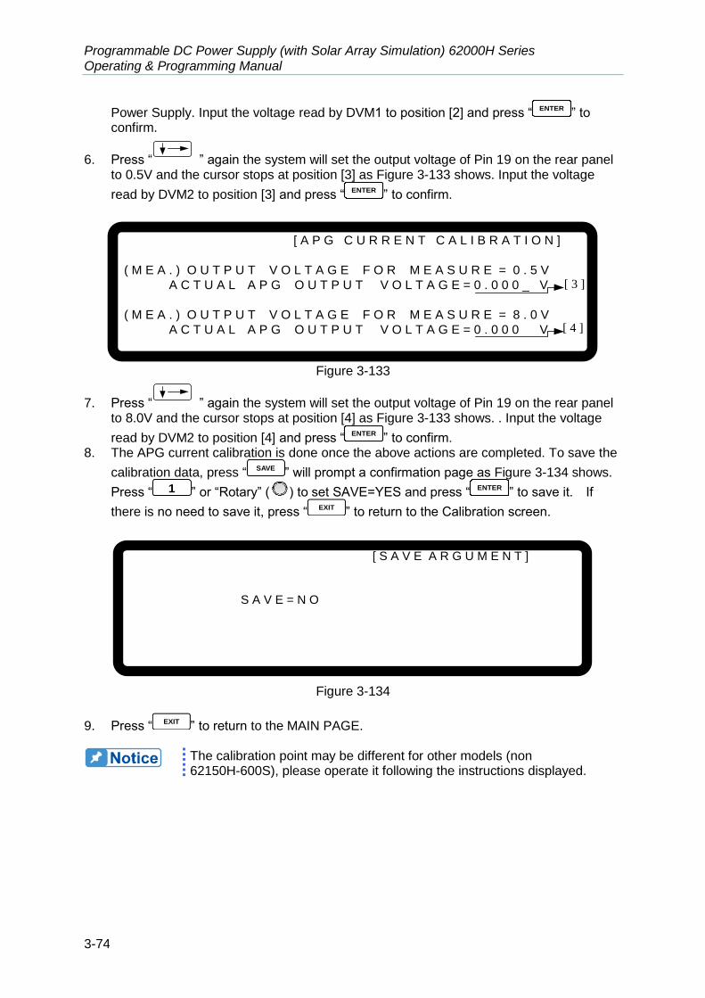
Programmable DC Power Supply (with Solar Array Simulation) 62000H Series Operating & Programming Manual
3-74
Power Supply. Input the voltage read by DVM1 to position [2] and press “ENTER
” to confirm.
6. Press “ ” again the system will set the output voltage of Pin 19 on the rear panel to 0.5V and the cursor stops at position [3] as Figure 3-133 shows. Input the voltage
read by DVM2 to position [3] and press “ENTER
” to confirm.
[ A P G C U R R E N T C A L I B R A T I O N ]
( M E A . ) O U T P U T V O L T A G E F O R M E A S U R E = 0 . 5 V
A C T U A L A P G O U T P U T V O L T A G E = 0 . 0 0 0 _ V
( M E A . ) O U T P U T V O L T A G E F O R M E A S U R E = 8 . 0 V
A C T U A L A P G O U T P U T V O L T A G E = 0 . 0 0 0 V
[ 3 ]
[ 4 ]
Figure 3-133
7. Press “ ” again the system will set the output voltage of Pin 19 on the rear panel to 8.0V and the cursor stops at position [4] as Figure 3-133 shows. . Input the voltage
read by DVM2 to position [4] and press “ENTER
” to confirm. 8. The APG current calibration is done once the above actions are completed. To save the
calibration data, press “ SAVE ” will prompt a confirmation page as Figure 3-134 shows.
Press “ 1 ” or “Rotary” (
) to set SAVE=YES and press “ENTER
” to save it. If
there is no need to save it, press “ EXIT ” to return to the Calibration screen.
[ S A V E A R G U M E N T ]
S A V E = N O
Figure 3-134
9. Press “EXIT
” to return to the MAIN PAGE.
The calibration point may be different for other models (non 62150H-600S), please operate it following the instructions displayed.

Manual Operation
3-75
3.3.7.6 IV Voltage Output & Measurement Calibration
(62020H-150S Only)
3.3.7.6.1 Hardware Requirements
The hardware required is shown in Table 3-11.
Table 3-11
Device Suggest Model or Capacity
DVM HP 34401A or equivalent DVM
3.3.7.6.2 Setup
The wiring is shown in Figure 3-135.
Figure 3-135
1. For device to perform calibration, its accuracy has to higher than the
specification. 2. Set the Resolution of HP34401 to SLOW 6 digit. 3. When conducting the current calibration, each calibration point has
to key in at least 5 Arabic numerals to ensure the Power Supply accuracy after calibration.
4. This calibration function is only valid for 62020H-150S.
3.3.7.6.3 Calibration Procedure
1. Enter into the screen as shown in Figure 3-136.
[C A L I B R A T I O N]
C H O I C E = V O L T A G E [ P / M ]
1 . V O L T A G E [ P R O G . / M E A S . ]
2 . C U R R E N T [ M E A S . ]
3 . C U R R E N T [ P R O G . ]
4 . A P G V O L T A G E [ P R O G . / M E A S . ]
5 . A P G C U R R E N T [ P R O G . / M E A S . ]
6 . I V V O L T A G E [ M E A S . ] 7 . I V C U R R E N T [ M E A S . ]
Figure 3-136

Programmable DC Power Supply (with Solar Array Simulation) 62000H Series Operating & Programming Manual
3-76
2. In the CALIBRATION page, press “ 1 ” or turn the “Rotary” (
) knob to set CHOICE=1.
3. Press “ENTER
” to confirm entering into Voltage Calibration as Figure 3-137 shown below.
[ V O L T A G E C A L I B R A T I O N ] R E M O V E E X T E R N A L L O A D A N D P R E S S [ E N T E R ] _
S E T T I N G O U T P U T V O L T A G E 1 0 . 0 0 V
A C T U A L O U T P U T V O L T A G E = 0 . 0 0 0 0 V
S E T T I N G O U T P U T V O L T A G E 2 9 . 0 0 V A C T U A L O U T P U T V O L T A G E = 0 . 0 0 0 0 V
Figure 3-137
4. When in Voltage Calibration page, press “ENTER
” to confirm. 5. First perform low voltage range calibration. The device will output 10.00V and the
cursor will stop at position [1] as shown in Figure 3-138. Enter the voltage read by
DVM to position [1] and press “ENTER
” to confirm it.
6. Next, press “ ” to do the low voltage range second point calibration. The device will output 29.00V and the cursor will stop at position [2] as shown in Figure 3-138.
Enter the voltage read by DVM to position [2] and press “ENTER
” to confirm it.
[V O L T A G E C A L I B R A T I O N]
R E M O V E E X T E R N A L L O A D A N D P R E S S[ E N T E R ]
S E T T I N G O U T P U T V O L T A G E 1 0 . 0 0 V A C T U A L O U T P U T V O L T A G E= 9 . 9 9 9 8 _ V
S E T T I N G O U T P U T V O L T A G E 2 9 . 0 0 V A C T U A L O U T P U T V O L T A G E=2 8 . V
[ 1 ]
[ 2 ]9 9 8 2
Figure 3-138
7. Press “ ” again to start the high voltage range calibration. The device will output 38.00V and the cursor will stop at position [3] as shown in Figure 3-139. Enter the
voltage read by DVM to position [3] and press “ENTER
” to confirm it.
8. Press “ ” one more time to do the high voltage range calibration. The device output 132.00V and the cursor will stop at position [4] as shown in Figure 3-139. Enter
the voltage read by DVM to position [4] and press “ENTER
” to confirm it.
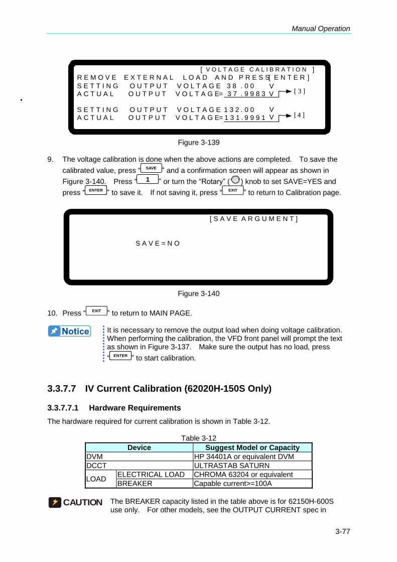
Manual Operation
3-77
[ V O L T A G E C A L I B R A T I O N ]
R E M O V E E X T E R N A L L O A D A N D P R E S S[ E N T E R ]
S E T T I N G O U T P U T V O L T A G E 3 8 . 0 0 V A C T U A L O U T P U T V O L T A G E= 3 7 . 9 9 8 3 V
S E T T I N G O U T P U T V O L T A G E 1 3 2 . 0 0 V
A C T U A L O U T P U T V O L T A G E= 1 3 1 . V
[ 3 ]
[ 4 ]9 9 9 1
Figure 3-139
9. The voltage calibration is done when the above actions are completed. To save the
calibrated value, press “ SAVE ” and a confirmation screen will appear as shown in
Figure 3-140. Press “ 1 ” or turn the “Rotary” (
) knob to set SAVE=YES and
press “ENTER
” to save it. If not saving it, press “ EXIT ” to return to Calibration page.
[ S A V E A R G U M E N T ]
S A V E = N O
Figure 3-140
10. Press “ EXIT ” to return to MAIN PAGE.
It is necessary to remove the output load when doing voltage calibration. When performing the calibration, the VFD front panel will prompt the text as shown in Figure 3-137. Make sure the output has no load, press
“ENTER
” to start calibration.
3.3.7.7 IV Current Calibration (62020H-150S Only)
3.3.7.7.1 Hardware Requirements
The hardware required for current calibration is shown in Table 3-12.
Table 3-12
Device Suggest Model or Capacity
DVM HP 34401A or equivalent DVM
DCCT ULTRASTAB SATURN
LOAD ELECTRICAL LOAD CHROMA 63204 or equivalent
BREAKER Capable current>=100A
CAUTION The BREAKER capacity listed in the table above is for 62150H-600S use only. For other models, see the OUTPUT CURRENT spec in

Programmable DC Power Supply (with Solar Array Simulation) 62000H Series Operating & Programming Manual
3-78
Table 1-1 for selecting the appropriate BREAKER.
3.3.7.7.2 SETUP
The connecting diagram for current calibration is shown in Figure 3-141.
62020H- 150 S
v
v
DVM
sv
sv
Electronic
Load
Breaker
ULTRASTAB
SATURN
Figure 3-141
1. Before using ULTRASTAB SATURN for current calibration, it needs
to calibrate the offset voltage of ULTRASTAB SATURN first. Press
“Null
” and the DVM panel digits will reset and show “Math” for current calibration.
2. When conducting the current calibration, each calibration point has to key in at least 5 Arabic numerals to ensure the Power Supply accuracy after calibration.
3.3.7.7.3 Calibration Procedure
1. Enter into the screen as shown in Figure 3-136.
2. In the CALIBRATION page, press “ 2 ” or turn the “Rotary” (
) knob to set CHOICE=2.
3. Press “ENTER
” to confirm entering into the current calibration as Figure 3-142 shown below.
[ C U R R E N T M E A S C A L I B R A T I O N ]
R E M O V E A L L L O A D I N G F R O M O U T P U T T E R M I N A L
P R E S S [ E N T E R ] W H E N R E A D Y
Figure 3-142

Manual Operation
3-79
4. Open the Breaker to ensure the DC Power Supply is in no load state and press “ENTER
” to confirm.
5. Next, the screen appears as shown in Figure 3-143. Press “ENTER
” to do the low current range calibration first. The system will output a fixed voltage and then set the Electronic Load to load 1.0A current. The cursor will stop at position [1] as shown in Figure 3-143. Enter the current read by the ULTRASTAB SATURN (DVM) to position
[1] and press “ENTER
” to confirm it.
[C U R R E N T M E A S C A L I B R A T I O N] A P P L Y L O A D I N G A N D P R E S S[ E N T E R ]
S E T L O A D I N G C U R R E N T = 1 . 0 0 0 A A C T U A L O U T P U T C U R R E N T= 0 . 0 0 0 0 _ A [ 1 ]
Figure 3-143
6. After 1.5A is calibrated, it is important to turn off the Electronic Load and reconnect the
DC Power Supply to the Current Shunt that covers 20A and close to the rated. For Prodigit 7550, use 20A current shunt directly.
7. Press “ ” to perform 6.7A calibration. The cursor will stop at position [2] as shown in Figure 3-144. Set the Electronic Load to load 6.700A current. Enter the current
read by the ULTRASTAB SATURN (DVM) to position [2] and press “ENTER
” to confirm. Using the calibration of 1.0A and 6.7A, the system will calculate the calibration factor of low current range.
[C U R R E N T M E A S C A L I B R A T I O N]
A P P L Y L O A D I N G A N D P R E S S[ E N T E R ]
S E T L O A D I N G C U R R E N T = 6 . 7 0 0 A A C T U A L O U T P U T C U R R E N T= 0 . 0 0 0 0 _ A [ 2 ]
Figure 3-144
8. For high current range calibration, press “ ” to perform 7.5A calibration. When the cursor stops at position [3] as shown in Figure 3-145, set the Electronic Load to load 12.00A current. Enter the current read by the ULTRASTAB SATURN (DVM) to position
[3] and press “ENTER
” to confirm it.

Programmable DC Power Supply (with Solar Array Simulation) 62000H Series Operating & Programming Manual
3-80
[C U R R E N T M E A S C A L I B R A T I O N]
A P P L Y L O A D I N G A N D P R E S S[ E N T E R ]
S E T L O A D I N G C U R R E N T = 1 2 . 0 0 0 A A C T U A L O U T P U T C U R R E N T= 0 . 0 0 0 0 _ A [ 3 ]
Figure 3-145
9. Next, press “ ” to do 36.00A calibration. When the cursor stops at position [4] as shown in Figure 3-146, set the Electronic Load to load 36.00A current. Enter the
current read by the ULTRASTAB SATURN (DVM) to position [4] and press “ENTER
” to confirm it. Using the calibration of 12.00A and 36.00A, the system will calculate the calibration factor of high current range.
[C U R R E N T M E A S C A L I B R A T I O N]
A P P L Y L O A D I N G A N D P R E S S[ E N T E R ]
S E T L O A D I N G C U R R E N T = 3 6 . 0 0 0 A A C T U A L O U T P U T C U R R E N T= 0 . 0 0 0 0 _ A [ 4 ]
Figure 3-146
10. The current calibration is done when the above actions are completed. To save the
calibrated value, press “ SAVE ” and a confirmation screen will appear as shown in
Figure 3-147. Press “ 1 ” or turn the “Rotary” (
) knob to set SAVE=YES and
press “ENTER
” to save it. If not saving it, press “ EXIT ” to return to Calibration page.
[ S A V E A R G U M E N T ]
S A V E = N O
Figure 3-147
11. Press “EXIT
” to return to the MAIN PAGE.
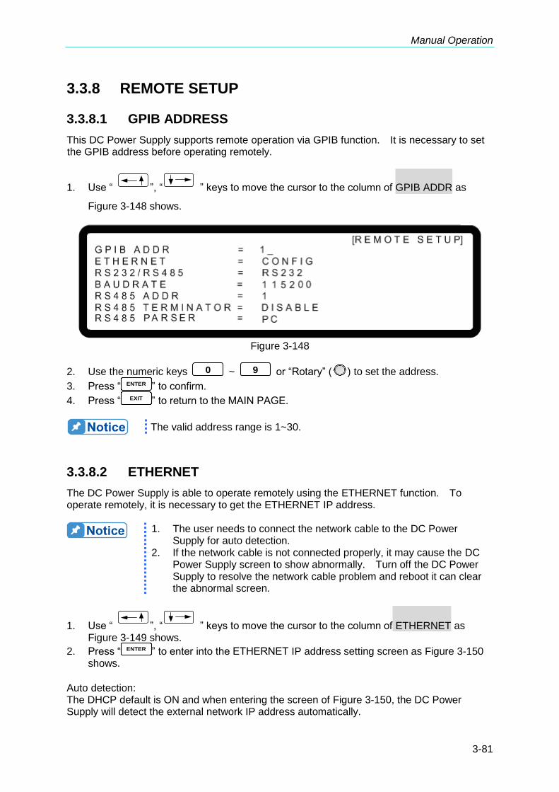
Manual Operation
3-81
3.3.8 REMOTE SETUP
3.3.8.1 GPIB ADDRESS
This DC Power Supply supports remote operation via GPIB function. It is necessary to set the GPIB address before operating remotely.
1. Use “ ”, “ ” keys to move the cursor to the column of GPIB ADDR as
Figure 3-148 shows.
Figure 3-148
2. Use the numeric keys 0 ~ 9 or “Rotary” (
) to set the address. 3. Press “ ENTER ” to confirm. 4. Press “ EXIT ” to return to the MAIN PAGE.
The valid address range is 1~30.
3.3.8.2 ETHERNET
The DC Power Supply is able to operate remotely using the ETHERNET function. To operate remotely, it is necessary to get the ETHERNET IP address.
1. The user needs to connect the network cable to the DC Power
Supply for auto detection. 2. If the network cable is not connected properly, it may cause the DC
Power Supply screen to show abnormally. Turn off the DC Power Supply to resolve the network cable problem and reboot it can clear the abnormal screen.
1. Use “ ”, “ ” keys to move the cursor to the column of ETHERNET as Figure 3-149 shows.
2. Press “ ENTER ” to enter into the ETHERNET IP address setting screen as Figure 3-150 shows.
Auto detection: The DHCP default is ON and when entering the screen of Figure 3-150, the DC Power Supply will detect the external network IP address automatically.
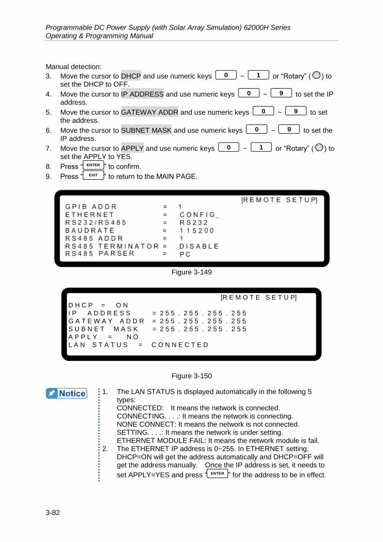
Programmable DC Power Supply (with Solar Array Simulation) 62000H Series Operating & Programming Manual
3-82
Manual detection: 3. Move the cursor to DHCP and use numeric keys 0 ~ 1 or “Rotary” (
) to
set the DHCP to OFF. 4. Move the cursor to IP ADDRESS and use numeric keys 0 ~ 9 to set the IP
address. 5. Move the cursor to GATEWAY ADDR and use numeric keys 0 ~ 9 to set
the address. 6. Move the cursor to SUBNET MASK and use numeric keys 0 ~ 9 to set the
IP address. 7. Move the cursor to APPLY and use numeric keys 0 ~ 1 or “Rotary” (
) to
set the APPLY to YES. 8. Press “ ENTER ” to confirm. 9. Press “ EXIT ” to return to the MAIN PAGE.
Figure 3-149
[R E M O T E S E T U P]
D H C P = O N
I P A D D R E S S = 2 5 5 . 2 5 5 . 2 5 5 . 2 5 5
G A T E W A Y A D D R = 2 5 5 . 2 5 5 . 2 5 5 . 2 5 5
S U B N E T M A S K = 2 5 5 . 2 5 5 . 2 5 5 . 2 5 5
A P P L Y = N O
L A N S T A T U S = C O N N E C T E D
Figure 3-150
1. The LAN STATUS is displayed automatically in the following 5
types: CONNECTED: It means the network is connected. CONNECTING. . . .: It means the network is connecting. NONE CONNECT: It means the network is not connected. SETTING. . . .: It means the network is under setting. ETHERNET MODULE FAIL: It means the network module is fail.
2. The ETHERNET IP address is 0~255. In ETHERNET setting, DHCP=ON will get the address automatically and DHCP=OFF will get the address manually. Once the IP address is set, it needs to
set APPLY=YES and press “ ENTER ” for the address to be in effect.

Manual Operation
3-83
3.3.8.3 RS232/RS485
1. Use “ ”, “ ” keys to move the cursor to the column of RS232/RS485 as Figure 3-151 shows.
Figure 3-151
2. Use numeric keys 0 ~ 1 or “Rotary” (
) to select RS232 or RS485. 3. Press “ ENTER ” to confirm. 4. Press “ EXIT ” to return to the MAIN PAGE.

Programmable DC Power Supply (with Solar Array Simulation) 62000H Series Operating & Programming Manual
3-84
3.3.8.4 BAUDRATE
The DC Power Supply is also able to operate remotely via RS-232. Before use it is necessary to set the RS-232 baudrate.
1. Use “ ”, “ ” keys to move the cursor to the column of BAUDRATE as Figure 3-152 shows.
Figure 3-152
2. Use the numeric keys 0 ~ 4 or “Rotary” (
) to select BAUDRATE. 3. Press “ ENTER ” to confirm. 4. Press “ EXIT ” to return to the MAIN PAGE.
There are 5 settings for BAUDRATE: 9600/19200/38400/57600/115200.
3.3.8.5 RS485 ADDR
The DC Power Supply also supports remote operation via RS485 function. It is necessary to set the RS485 address before operating remotely.
1. Use “ ”, “ ” keys to move the cursors to the column of RS485 ADDR as
Figure 3-153 shows.
Figure 3-153
2. Use the numeric keys 0 ~ 9 or “Rotary” (
) to set the address.
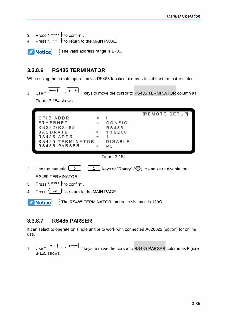
Manual Operation
3-85
3. Press “ ENTER ” to confirm. 4. Press “ EXIT ” to return to the MAIN PAGE.
The valid address range is 1~30.
3.3.8.6 RS485 TERMINATOR
When using the remote operation via RS485 function, it needs to set the terminator status.
1. Use “ ”, “ ” keys to move the cursor to RS485 TERMINATOR column as
Figure 3-154 shows.
Figure 3-154
2. Use the numeric 0 ~ 1 keys or “Rotary” (
) to enable or disable the
RS485 TERMINATOR.
3. Press “ ENTER ” to confirm.
4. Press “ EXIT ” to return to the MAIN PAGE.
The RS485 TERMINATOR internal resistance is 120Ω.
3.3.8.7 RS485 PARSER
It can select to operate on single unit or to work with connected A620029 (option) for online use.
1. Use “ ”, “ ” keys to move the cursor to RS485 PARSER column as Figure 3-155 shows.
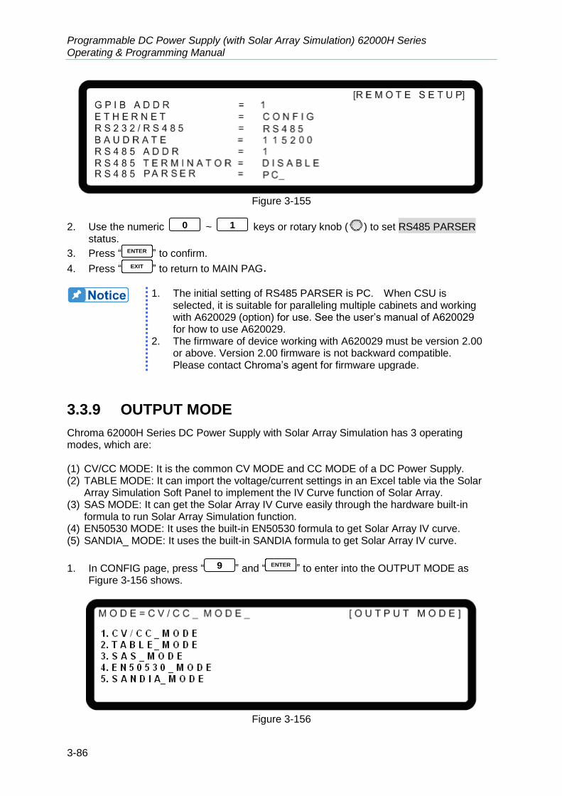
Programmable DC Power Supply (with Solar Array Simulation) 62000H Series Operating & Programming Manual
3-86
Figure 3-155
2. Use the numeric 0 ~ 1 keys or rotary knob (
) to set RS485 PARSER status.
3. Press “ ENTER ” to confirm.
4. Press “ EXIT ” to return to MAIN PAG.
1. The initial setting of RS485 PARSER is PC. When CSU is
selected, it is suitable for paralleling multiple cabinets and working with A620029 (option) for use. See the user’s manual of A620029 for how to use A620029.
2. The firmware of device working with A620029 must be version 2.00 or above. Version 2.00 firmware is not backward compatible. Please contact Chroma’s agent for firmware upgrade.
3.3.9 OUTPUT MODE
Chroma 62000H Series DC Power Supply with Solar Array Simulation has 3 operating modes, which are: (1) CV/CC MODE: It is the common CV MODE and CC MODE of a DC Power Supply. (2) TABLE MODE: It can import the voltage/current settings in an Excel table via the Solar
Array Simulation Soft Panel to implement the IV Curve function of Solar Array. (3) SAS MODE: It can get the Solar Array IV Curve easily through the hardware built-in
formula to run Solar Array Simulation function. (4) EN50530 MODE: It uses the built-in EN50530 formula to get Solar Array IV curve. (5) SANDIA_ MODE: It uses the built-in SANDIA formula to get Solar Array IV curve.
1. In CONFIG page, press “ 9 ” and “ENTER
” to enter into the OUTPUT MODE as Figure 3-156 shows.
Figure 3-156

Manual Operation
3-87
2. Use the numeric 0 ~ 2 keys or “Rotary” (
) knob to select the OUTPUT MODE. The default is CV/CC MODE.
3. Press “ENTER
” to confirm.
4. Press “EXIT
” to return to the MAIN PAGE.
3.3.9.1 CV/CC MODE
In addition to the function of Solar Array Simulation the models of Chroma 62000H Series DC Power Supplies with Solar Array Simulation can also be used as general DC Power Supply. Thus the operating mode still has CV mode and CC mode as Figure 3-157 shows. See section 3.2 for detail operating procedures.
CV1CV2
CC1
CC2
Figure 3-157
3.3.9.2 TABLE MODE
To use this function in a DC Power Supply it has to work with the Solar Array Simulation Soft Panel. The user can edit the IV Curve data in Excel and use the software to import the IV Curve data to DC Power Supply for Solar Array Simulation. The mode allows the user to edit various IV Curves as Figure 3-158 shows to generate the Solar Cell IV Curves of many types or the IV Curves under different operating environments such as irradiation change, temperature change, cloud shadow etc. It can also change the curve in real time to facilitate the user when using the IV Curves under various conditions.
(a) (b)
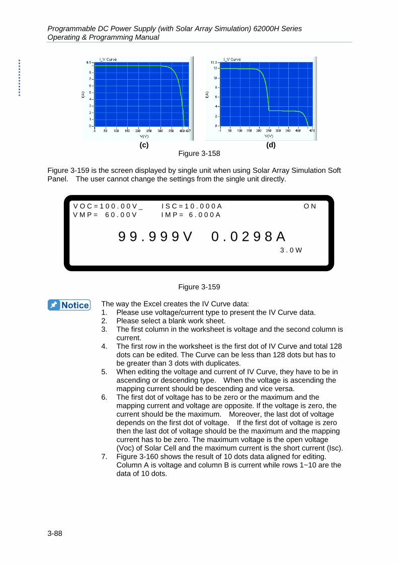
Programmable DC Power Supply (with Solar Array Simulation) 62000H Series Operating & Programming Manual
3-88
(c) (d)
Figure 3-158 Figure 3-159 is the screen displayed by single unit when using Solar Array Simulation Soft Panel. The user cannot change the settings from the single unit directly.
V O C = 1 0 0 . 0 0 V _ I S C = 1 0 . 0 0 0 A O N
V M P = 6 0 . 0 0 V I M P = 6 . 0 0 0 A
9 9 . 9 9 9 V 0 . 0 2 9 8 A 3 . 0 W
Figure 3-159
The way the Excel creates the IV Curve data: 1. Please use voltage/current type to present the IV Curve data. 2. Please select a blank work sheet. 3. The first column in the worksheet is voltage and the second column is
current. 4. The first row in the worksheet is the first dot of IV Curve and total 128
dots can be edited. The Curve can be less than 128 dots but has to be greater than 3 dots with duplicates.
5. When editing the voltage and current of IV Curve, they have to be in ascending or descending type. When the voltage is ascending the mapping current should be descending and vice versa.
6. The first dot of voltage has to be zero or the maximum and the mapping current and voltage are opposite. If the voltage is zero, the current should be the maximum. Moreover, the last dot of voltage depends on the first dot of voltage. If the first dot of voltage is zero then the last dot of voltage should be the maximum and the mapping current has to be zero. The maximum voltage is the open voltage (Voc) of Solar Cell and the maximum current is the short current (Isc).
7. Figure 3-160 shows the result of 10 dots data aligned for editing. Column A is voltage and column B is current while rows 1~10 are the data of 10 dots.

Manual Operation
3-89
Figure 3-160
3.3.9.3 SAS MODE
Chroma 62000H Series DC Power Supply with Solar Array Simulation not only able to simulate the Solar Cell curve via the Solar Array Simulation Soft Panel but also has built in model to provide solar cell curve simulation function that is called SAS Mode. Please see Britton, Lunscher, and Tanju, "A 9 KW High-Performance Solar Array Simulator", Proceedings of the European Space Power Conference, August 1993 (ESA WPP-054, August 1993) for the built-in model. The model formula discussed in the thesis is described as below.
oc
scs
scs
N
sc
oc
V
IR
IIRI
IV
V
1
2ln
2ln
where
mp
mpoc
sI
VVR
,
sc
mp
a
I
IN
ln
22ln,
oc
scmps
oc
scsmp
V
IIRV
IRV
a
1
Voc: Open Circuit Voltage Isc: Short Circuit Current Vmp: Max. Power Voltage Imp: Max. Power Current Moreover, due to the fact the model formula will use the inputted Vmp and Imp to get the maximum power point, the calculated Vmp and Imp will be different. The smaller Fill Factor (FF) the bigger difference they will be. Therefore, as well as the settings of the 4 parameters
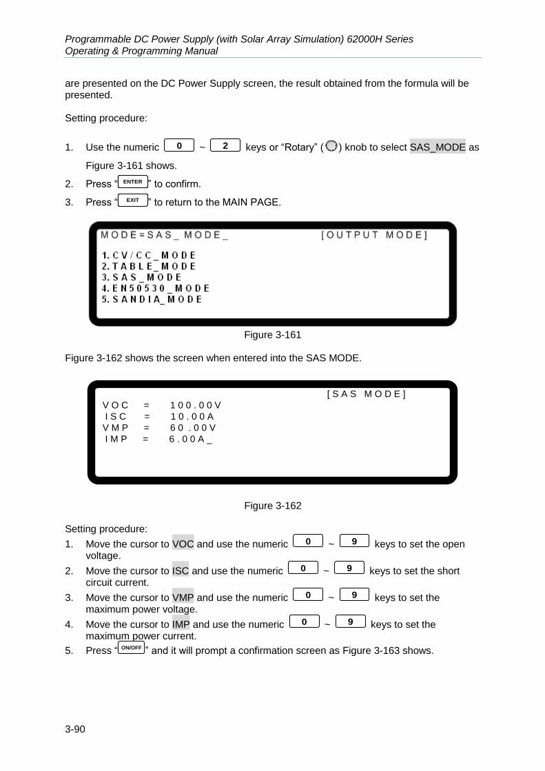
Programmable DC Power Supply (with Solar Array Simulation) 62000H Series Operating & Programming Manual
3-90
are presented on the DC Power Supply screen, the result obtained from the formula will be presented. Setting procedure:
1. Use the numeric 0 ~ 2 keys or “Rotary” (
) knob to select SAS_MODE as
Figure 3-161 shows.
2. Press “ ENTER ” to confirm.
3. Press “ EXIT ” to return to the MAIN PAGE.
Figure 3-161
Figure 3-162 shows the screen when entered into the SAS MODE.
[ S A S M O D E ]
V O C = 1 0 0 . 0 0 V
I S C = 1 0 . 0 0 A
V M P = 6 0 . 0 0 V
I M P = 6 . 0 0 A _
Figure 3-162
Setting procedure:
1. Move the cursor to VOC and use the numeric 0 ~ 9 keys to set the open voltage.
2. Move the cursor to ISC and use the numeric 0 ~ 9 keys to set the short circuit current.
3. Move the cursor to VMP and use the numeric 0 ~ 9 keys to set the maximum power voltage.
4. Move the cursor to IMP and use the numeric 0 ~ 9 keys to set the maximum power current.
5. Press “ ON/OFF ” and it will prompt a confirmation screen as Figure 3-163 shows.

Manual Operation
3-91
Figure 3-163
6. Press “ ON/OFF ” again for execution. It will jump to the SAS MODE main screen as
Figure 3-164 shows. To quit, press “ EXIT ” to return to the MAIN PAGE.
Figure 3-164
Figure 3-164 shows the screen when the SAS MODE outputs. The EQ_PMP, EQ_VMP and EQ_IMP are the actual operating points that are calculated from the settings of user VMP and IMP via the hardware built-in formula.
The user can change the VOC, ISC, VMP and IMP parameters directly using the “ ”,
“ ” function keys from the screen of single unit. When any of the VOC, ISC, VMP or
IMP is modified, use “ ” to move the cursor to TRIG and press “ENTER
” to confirm. The IV curve will update immediately and so too the EQ_PMP, EQ_VMP and EQ_IMP parameters.
1. Definition of Fill Factor (FF): scoc
mpmp
IV
IVFF
2. Voc,Vmp,Isc & Imp parameters setting limit:
a. 0 mpoc VV
b. 0 mpsc II
c.
sc
mp
ocmpI
IVV 1

Programmable DC Power Supply (with Solar Array Simulation) 62000H Series Operating & Programming Manual
3-92
3.
I-V Curve Programming Response Time (Typical)
62050H-600S Delta V= 600 to 0V (1s @ No Load)
(40ms @ 500W ) (8ms @ 2500W )
Delta V=350 to 250V (160ms @ No Load) (6.6ms @ 500W )
(1.4ms @ 2500W )
62100H-600S
Delta V= 600 to 0V (1s @ No Load) (40ms @ 1000W ) (8ms @ 5000W )
Delta V=350 to 250V (160ms @ No Load) (6.6ms @ 1000W )
(1.4ms @ 5000W )
62150H-600S
Delta V= 600 to 0V (1s @ No Load)
(40ms @ 1500W ) (8ms @ 7500W )
Delta V=350 to 250V (160ms @ No Load) (6.6ms @ 1500W )
(1.4ms @ 7500W )
62150H-1000S Delta V= 1000 to 0V (1.5s @ No Load)
(40ms @ 1500W ) (8ms @ 7500W )
Delta V=580 to 420V (240ms @ No Load) (6.4ms @ 1500W )
(1.3ms @ 7500W )
A620028 Delta V= 1000 to 0V (1.5s @ No Load)
(40ms @ 1500W ) (8ms @ 7500W )
Delta V=580 to 420V (240ms @ No Load) (6.4ms @ 1500W )
(1.3ms @ 7500W )
A620027 Delta V= 600 to 0V (1s @ No Load)
(40ms @ 1500W ) (8ms @ 7500W )
Delta V=350 to 250V (160ms @ No Load) (6.6ms @ 1500W )
(1.4ms @ 7500W )
62020H-150S Delta V= 150 to 0V (120ms @ No Load)
(16ms @ 200W )

Manual Operation
3-93
(3.2ms @ 1000W ) Delta V=50 to 20V (25ms @ No Load) (1.5ms @ 200W )
(0.3ms @ 1000W )
3.3.9.4 EN50530 MODE
Chroma 62000H Series Programmable DC Power Supply (with Solar Array Simulation) besides can simulate the solar cell curve via Solar Array Simulation Soft Panel, it also has EN50530 built in to provide solar cell curve simulation function.
1. Use the numeric 0 ~ keys or rotary knob (
) to select EN50530_MODE as Figure 3-165 shows.
2. Press “ ENTER ” to confirm. 3. Press “ EXIT ” to return to the MAIN PAGE.
Figure 3-165
When in EN50530 _MODE, the screen shows as Figure 3-166.
Figure 3-166
Setting Procedure:
1. Move the cursor to VMP and use the numeric keys ( 0 ~ 9 ) to set the maximum power voltage.
2. Move the cursor to PMP and use the numeric keys ( 0 ~ 9 ) to set the maximum power.
3. Move the cursor to FF and use the numeric keys ( 0 ~ 9 ) to set the PV fill factor.

Programmable DC Power Supply (with Solar Array Simulation) 62000H Series Operating & Programming Manual
3-94
4. Move the cursor to IRR and use the numeric keys ( 0 ~ 9 ) to set the irradiation.
5. Press “ ON/OFF ” will prompt a confirmation window as Figure 3-167 shows.
Figure 3-167
6. Press “ ON/OFF ” again to confirm the execution and it will go to the EN50530 MODE main
screen as Figure 3-168 shows. To quit, press “ EXIT ” to return to the MAIN PAGE.
Figure 3-168
Figure 3-168 shows the screen when EN50530_MODE outputs. The EQ_VOC, EQ_VMP, EQ_ISC and EQ_IMP are the actual operating points that are calculated based on the settings set by the user of VMP and PMP via the hardware built-in formula.
Use “ ” and “ ” to change the VMP and PMP parameters directly on the single
unit screen. When the parameter of VMP or PMP is change, use “ ” to move the
cursor to TRIG and press “ENTER
” to confirm the change. The IV curve will update immediately and so too the EQ_VOC, EQ_VMP, EQ_ISC and EQ_IMP parameters.
3.3.9.5 SANDIA MODE
Chroma 62000H Series Programmable DC Power Supply (with Solar Array Simulation) besides can simulate the solar cell curve via Solar Array Simulation Soft Panel, it also has SANDIA_MODE built in to provide solar cell curve simulation function.
1. Use the numeric 0 ~ keys or rotary knob (
) to select SANDIA_MODE as Figure 3-169 shows.
2. Press “ENTER
” to confirm.
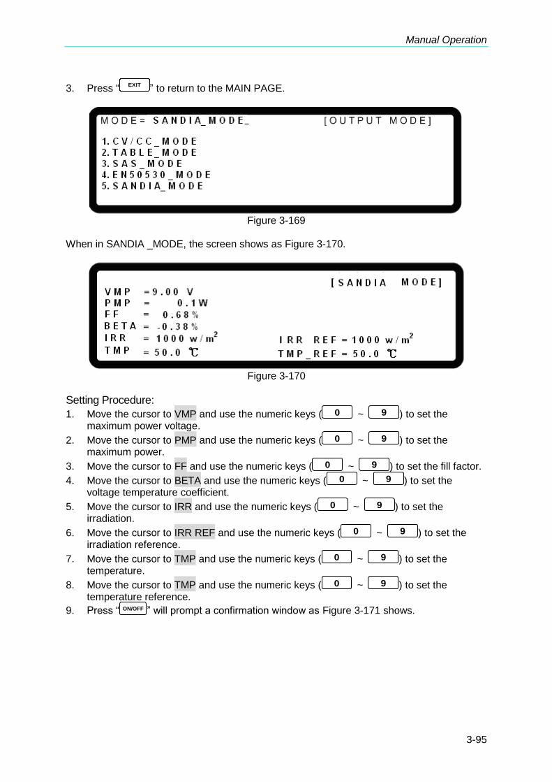
Manual Operation
3-95
3. Press “EXIT
” to return to the MAIN PAGE.
Figure 3-169
When in SANDIA _MODE, the screen shows as Figure 3-170.
Figure 3-170
Setting Procedure:
1. Move the cursor to VMP and use the numeric keys ( 0 ~ 9 ) to set the maximum power voltage.
2. Move the cursor to PMP and use the numeric keys ( 0 ~ 9 ) to set the maximum power.
3. Move the cursor to FF and use the numeric keys ( 0 ~ 9 ) to set the fill factor. 4. Move the cursor to BETA and use the numeric keys ( 0 ~ 9 ) to set the
voltage temperature coefficient. 5. Move the cursor to IRR and use the numeric keys ( 0 ~ 9 ) to set the
irradiation. 6. Move the cursor to IRR REF and use the numeric keys ( 0 ~ 9 ) to set the
irradiation reference. 7. Move the cursor to TMP and use the numeric keys ( 0 ~ 9 ) to set the
temperature. 8. Move the cursor to TMP and use the numeric keys ( 0 ~ 9 ) to set the
temperature reference. 9. Press “ ON/OFF ” will prompt a confirmation window as Figure 3-171 shows.
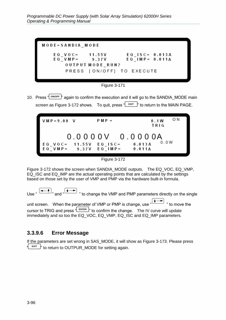
Programmable DC Power Supply (with Solar Array Simulation) 62000H Series Operating & Programming Manual
3-96
Figure 3-171
10. Press “ ON/OFF ” again to confirm the execution and it will go to the SANDIA_MODE main
screen as Figure 3-172 shows. To quit, press “ EXIT ” to return to the MAIN PAGE.
Figure 3-172
Figure 3-172 shows the screen when SANDIA_MODE outputs. The EQ_VOC, EQ_VMP, EQ_ISC and EQ_IMP are the actual operating points that are calculated by the settings based on those set by the user of VMP and PMP via the hardware built-in formula.
Use “ ” and “ ” to change the VMP and PMP parameters directly on the single
unit screen. When the parameter of VMP or PMP is change, use “ ” to move the
cursor to TRIG and press “ENTER
” to confirm the change. The IV curve will update immediately and so too the EQ_VOC, EQ_VMP, EQ_ISC and EQ_IMP parameters.
3.3.9.6 Error Message
If the parameters are set wrong in SAS_MODE, it will show as Figure 3-173. Please press
“EXIT
” to return to OUTPUR_MODE for setting again.

Manual Operation
3-97
Figure 3-173
When in EN50530 or SANDIA_MODE setting screen, if the parameter shows negative after
calculation, the screen will show as Figure 3-174. Please press “EXIT
” to return to OUTPUR_MODE for setting again.
Figure 3-174

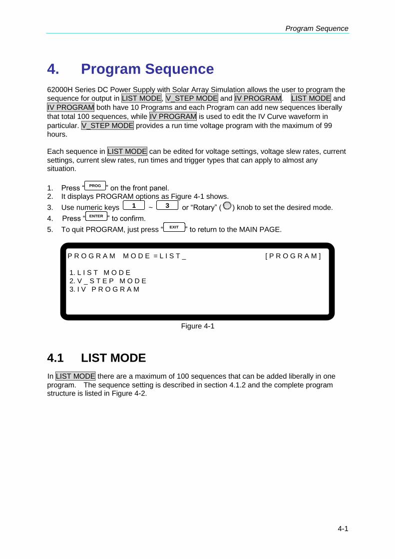
Program Sequence
4-1
4. Program Sequence
62000H Series DC Power Supply with Solar Array Simulation allows the user to program the
sequence for output in LIST MODE, V_STEP MODE and IV PROGRAM. LIST MODE and
IV PROGRAM both have 10 Programs and each Program can add new sequences liberally
that total 100 sequences, while IV PROGRAM is used to edit the IV Curve waveform in
particular. V_STEP MODE provides a run time voltage program with the maximum of 99
hours.
Each sequence in LIST MODE can be edited for voltage settings, voltage slew rates, current
settings, current slew rates, run times and trigger types that can apply to almost any situation.
1. Press “ PROG ” on the front panel. 2. It displays PROGRAM options as Figure 4-1 shows.
3. Use numeric keys 1 ~ 3 or “Rotary” (
) knob to set the desired mode.
4. Press “ENTER
” to confirm.
5. To quit PROGRAM, just press “EXIT
” to return to the MAIN PAGE.
P R O G R A M M O D E = L I S T _ [ P R O G R A M ]
1. L I S T M O D E
2. V _ S T E P M O D E
3. I V P R O G R A M
Figure 4-1
4.1 LIST MODE
In LIST MODE there are a maximum of 100 sequences that can be added liberally in one
program. The sequence setting is described in section 4.1.2 and the complete program structure is listed in Figure 4-2.

Programmable DC Power Supply (with Solar Array Simulation) 62000H Series Operating & Programming Manual
4-2
[ PROGRAM ]
PROG NO. = 1
RUN COUNT = 1
PROG CHAIN = NO
CLEAR PROG = NO
[ SEQUENCE ]
SEQ NO. = 1
SEQ TYPE = AUTO TIME = 0.000(S)
VOLTAGE = 0.00V
V S. R. = 1.000(V/ms)
CURRENT = 0.000A
I S. R. = INF. (A/ms)
[ SEQUENCE ]
SEQ NO. = 2
SEQ TYPE = AUTO TIME = 0.000(S)
VOLTAGE = 0.00V
V S. R. = 1.000(V/ms)
CURRENT = 0.000A
I S. R. = INF. (A/ms)
[ SEQUENCE ]
SEQ NO. = 3
SEQ TYPE = AUTO TIME = 0.000(S)
VOLTAGE = 0.00V
V S. R. = 1.000(V/ms)
CURRENT = 0.000A
I S. R. = INF. (A/ms)
[ SEQUENCE ]
SEQ NO. = 4
SEQ TYPE = AUTO TIME = 0.000(S)
VOLTAGE = 0.00V
V S. R. = 1.000(V/ms)
CURRENT = 0.000A
I S. R. = INF. (A/ms)
↓
↓
↓
EXT._TRIG PULL = HIGH
Figure 4-2
4.1.1 Description of PROGRAM Settings
A PROGGRAM has 5 settings: (1) EXT._TRIG PULL, (2) PROG NO., (3) RUN COUNT, (4)
PROG CHAIN and (5) CLEAR PROG.
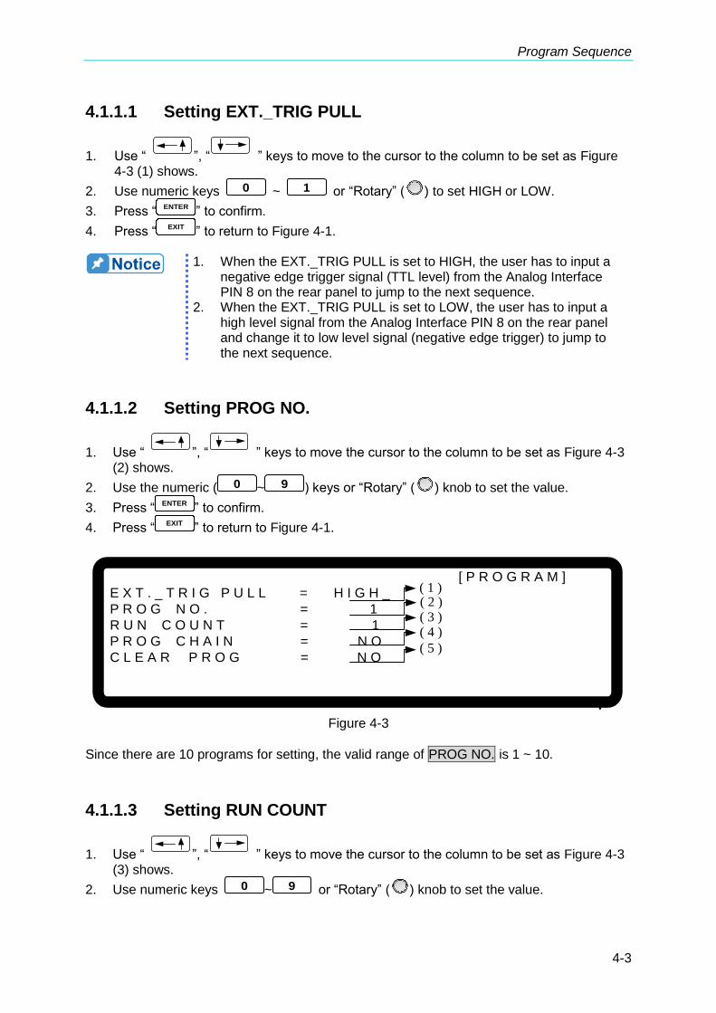
Program Sequence
4-3
4.1.1.1 Setting EXT._TRIG PULL
1. Use “ ”, “ ” keys to move to the cursor to the column to be set as Figure 4-3 (1) shows.
2. Use numeric keys 0 ~ 1 or “Rotary” (
) to set HIGH or LOW.
3. Press “ENTER
” to confirm.
4. Press “EXIT
” to return to Figure 4-1.
1. When the EXT._TRIG PULL is set to HIGH, the user has to input a
negative edge trigger signal (TTL level) from the Analog Interface PIN 8 on the rear panel to jump to the next sequence.
2. When the EXT._TRIG PULL is set to LOW, the user has to input a high level signal from the Analog Interface PIN 8 on the rear panel and change it to low level signal (negative edge trigger) to jump to the next sequence.
4.1.1.2 Setting PROG NO.
1. Use “ ”, “ ” keys to move the cursor to the column to be set as Figure 4-3 (2) shows.
2. Use the numeric ( 0 ~ 9 ) keys or “Rotary” (
) knob to set the value.
3. Press “ENTER
” to confirm.
4. Press “EXIT
” to return to Figure 4-1.
[ P R O G R A M ]
E X T . _ T R I G P U L L = H I G H _
P R O G N O . = 1
R U N C O U N T = 1
P R O G C H A I N = N O
C L E A R P R O G = N O
▼
( 1 )( 2 )( 3 )( 4 )
( 5 )
Figure 4-3
Since there are 10 programs for setting, the valid range of PROG NO. is 1 ~ 10.
4.1.1.3 Setting RUN COUNT
1. Use “ ”, “ ” keys to move the cursor to the column to be set as Figure 4-3 (3) shows.
2. Use numeric keys 0 ~ 9 or “Rotary” (
) knob to set the value.
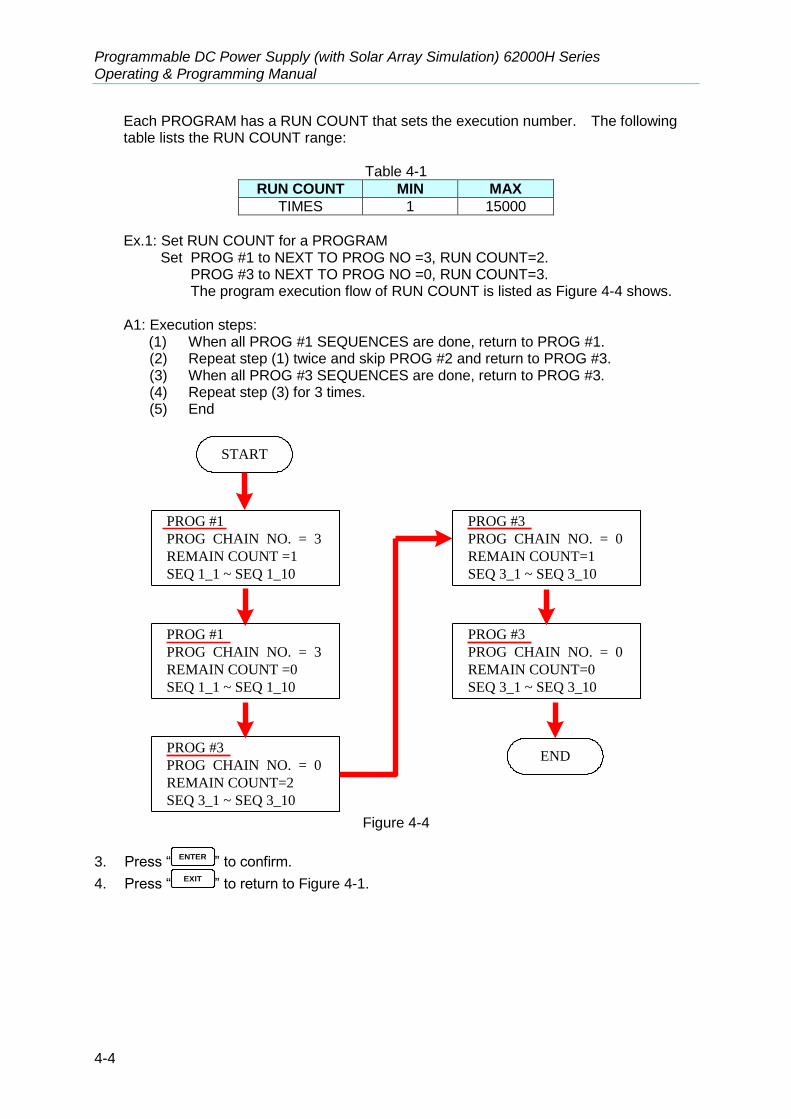
Programmable DC Power Supply (with Solar Array Simulation) 62000H Series Operating & Programming Manual
4-4
Each PROGRAM has a RUN COUNT that sets the execution number. The following table lists the RUN COUNT range:
Table 4-1
RUN COUNT MIN MAX
TIMES 1 15000
Ex.1: Set RUN COUNT for a PROGRAM
Set PROG #1 to NEXT TO PROG NO =3, RUN COUNT=2. PROG #3 to NEXT TO PROG NO =0, RUN COUNT=3.
The program execution flow of RUN COUNT is listed as Figure 4-4 shows. A1: Execution steps:
(1) When all PROG #1 SEQUENCES are done, return to PROG #1. (2) Repeat step (1) twice and skip PROG #2 and return to PROG #3. (3) When all PROG #3 SEQUENCES are done, return to PROG #3. (4) Repeat step (3) for 3 times. (5) End
PROG #1
PROG CHAIN NO. = 3
REMAIN COUNT =1
SEQ 1_1 ~ SEQ 1_10
PROG #3
PROG CHAIN NO. = 0
REMAIN COUNT=2
SEQ 3_1 ~ SEQ 3_10
START
PROG #1
PROG CHAIN NO. = 3
REMAIN COUNT =0
SEQ 1_1 ~ SEQ 1_10
PROG #3
PROG CHAIN NO. = 0
REMAIN COUNT=1
SEQ 3_1 ~ SEQ 3_10
PROG #3
PROG CHAIN NO. = 0
REMAIN COUNT=0
SEQ 3_1 ~ SEQ 3_10
END
Figure 4-4
3. Press “ENTER
” to confirm.
4. Press “EXIT
” to return to Figure 4-1.

Program Sequence
4-5
4.1.1.4 Setting PROG CHAIN
1. Use “ ”, “ ” keys to move the cursor to the column to be set as Figure 4-3 (4) shows.
2. Use numeric keys 0 ~ 1 or “Rotary” (
) knob to set YES or NO.
The PROGRAM CHAIN indicates the link among programs. YES must be set before executing different programs, and then select the PROGRAM to be executed next (NEXT TO PROG NO.). The setting range is 0 ~ 10. (1) Set NEXT TO PROG NO. to 0
When setting NEXT TO PROG NO. to 0, it means no program link.
(2) Set NEXT TO PROG NO. to non 0
When setting NEXT TO PROG NO. to non-0, it means to perform program link as
the example listed below.
Ex.: Link execution among programs Set PROG #1 to NEXT TO PROG NO =3, RUN COUNT=1
PROG #3 to NEXT TO PROG NO =4, RUN COUNT=1 PROG #4 to NEXT TO PROG NO =6, RUN COUNT=1 PROG #6 to NEXT TO PROG NO =0, RUN COUNT=1
The program execution flow is listed as Figure 4-5 shows.
A2: Execution steps: (1) When all PROG #1 SEQUENCES are done, skip PROG #2 and jump to
PROG #3 (2) When all PROG #3 SEQUENCES are done, jump to PROG #4 (3) When all PROG #4 SEQUENCES are done, skip PROG #5 and jump to
PROG #6 (4) End

Programmable DC Power Supply (with Solar Array Simulation) 62000H Series Operating & Programming Manual
4-6
PROG #1
PROG CHAIN NO = 3
SEQ 1_1 ~ SEQ 1_10
PROG #2
PROG CHAIN NO = 0
SEQ 2_1 ~ SEQ 2_10
PROG #3
PROG CHAIN NO = 4
SEQ 3_1 ~ SEQ 3_10
PROG #4
PROG CHAIN NO = 6
SEQ 4_1 ~ SEQ 4_10
PROG #5
PROG CHAIN NO = 0
SEQ 5_1 ~ SEQ 5_10
PROG #6
PROG CHAIN NO = 0
SEQ 6_1 ~ SEQ 6_10
PROG #7
PROG CHAIN NO = 0
SEQ 7_1 ~ SEQ 7_10
PROG #8
PROG CHAIN NO = 0
SEQ 8_1 ~ SEQ 8_10
PROG #9
PROG CHAIN NO = 0
SEQ 9_1 ~ SEQ 9_10
PROG #10
PROG CHAIN NO = 0
SEQ 10_1 ~ SEQ 10_10
END
START
Figure 4-5
Ex. 3: Use a PROGRAM to form an infinite loop
Set PROG #1 to NEXT TO PROG NO =1, RUN COUNT=1 The program execution flow is listed as Figure 4-6 shows.
A3: Execution steps:
(1) When all PROG #1 SEQUENCES are done, jump to PROG #1. (2) Rerun step (1). (3) Form an infinite loop.

Program Sequence
4-7
PROG #1
PROG CHAIN NO. = 1
SEQ 1_1 ~ SEQ 1_10
START
Figure 4-6
Ex.4: Use multiple PROGRAMS to form an infinite loop
Set PROG #1 to NEXT TO PROG NO =3, RUN COUNT=1 PROG #3 to NEXT TO PROG NO =4, RUN COUNT=1 PROG #4 to NEXT TO PROG NO =6, RUN COUNT=1
PROG #6 to NEXT TO PROG NO =1, RUN COUNT=1 The program execution flow is listed as Figure 4-7shows.
A4: Execution steps:
(1) When all PROG #1 SEQUENCES are done, skip PROG #2 and jump to PROG #3.
(2) When all PROG #3 SEQUENCES are done, jump to PROG #4. (3) When all PROG #4 SEQUENCES are done, skip PROG #5 and jump to
PROG #6. (4) When all PROG #6 SEQUENCES are done, skip PROG #7~ PROG #10 and
jump to PROG #1. (5) Rerun step (1) ~ step (4). (6) Form an infinite loop.
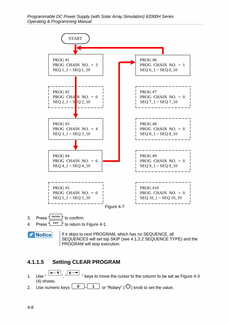
Programmable DC Power Supply (with Solar Array Simulation) 62000H Series Operating & Programming Manual
4-8
PROG #1
PROG CHAIN NO. = 3
SEQ 1_1 ~ SEQ 1_10
PROG #2
PROG CHAIN NO. = 0
SEQ 2_1 ~ SEQ 2_10
PROG #3
PROG CHAIN NO. = 4
SEQ 3_1 ~ SEQ 3_10
PROG #4
PROG CHAIN NO. = 6
SEQ 4_1 ~ SEQ 4_10
PROG #5
PROG CHAIN NO. = 0
SEQ 5_1 ~ SEQ 5_10
PROG #6
PROG CHAIN NO. = 1
SEQ 6_1 ~ SEQ 6_10
PROG #7
PROG CHAIN NO. = 0
SEQ 7_1 ~ SEQ 7_10
PROG #8
PROG CHAIN NO. = 0
SEQ 8_1 ~ SEQ 8_10
PROG #9
PROG CHAIN NO. = 0
SEQ 9_1 ~ SEQ 9_10
PROG #10
PROG CHAIN NO. = 0
SEQ 10_1 ~ SEQ 10_10
START
Figure 4-7
3. Press “ENTER
” to confirm.
4. Press “EXIT
” to return to Figure 4-1.
If it skips to next PROGRAM, which has no SEQUENCE, all SEQUENCES will set top SKIP (see 4.1.2.2 SEQUENCE TYPE) and the PROGRAM will stop execution.
4.1.1.5 Setting CLEAR PROGRAM
1. Use “ ”, “ ” keys to move the cursor to the column to be set as Figure 4-3 (4) shows.
2. Use numeric keys 0 ~ 1 or “Rotary” (
) knob to set the value.

Program Sequence
4-9
Clear Program has two options, which are CLEAR PROG. = YES / NO. The main
function of Clear Program is to clear all sequences in that program.
3. Press “ENTER
” to confirm.
4. Press “EXIT
” to return to Figure 4-1.
4.1.2 Setting Sequence
1. The default SEQUENCE of all PROGRAMS is 0 and maximum 100 SEQUENCES can be added freely to a PROGRAM. In other words, the total SEQUENCES to be used by 10 PROGRAMS are 100 maximum.
2. Adding a new SEQUENCE:
a. In PROGRAM page (Figure 4-3), if the PROGRAM has no SEQUENCE when the
cursor is at (5), press “ ” can add a new SEQUENCE. The page will skip to Figure 4-8.
b. When the cursor is at (7) in Figure 4-8 as the SEQUENCE of a PROGRAM, press
“ ” can add a new SEQUENCE.
“ ” function key is usually used as cursor movement key, only when in the above situations can it be used for adding new SEQUENCE.
3. Use “ ”, “ ” keys to move the cursor to the column to be set as Figure 4-8 shows.
4. Use numeric keys 0 ~ 9 or “Rotary” (
) knob to set the value.
[ S E Q U E N C E ]
S E Q N O = 1 _
S E Q T Y P E = A U T O T I M E = 0 . 0 0 0 ( S )
V O L T A G E = 0 . 0 0 V
V S . R . = 1 . 0 0 0 ( V/ m s )
C U R R E N T = 0 . 0 0 0 A
I S . R . = I N F . ( A / m s ) ▲
▼
( 1 )( 2 )
( 4 )( 5 )
( 6 )
( 7 )
( 3 )
Figure 4-8
Each sequence has seven options: (1) SEQ NO., (2) SEQ. TYPE, (3) TIME, (4)
VOLTAGE, (5) V S.R., (6) CURRENT and (7) I S.R. which are described as below.
5. Press “ENTER
” to confirm.
6. Press “EXIT
” to return to Program PAGE (Figure 4-3).
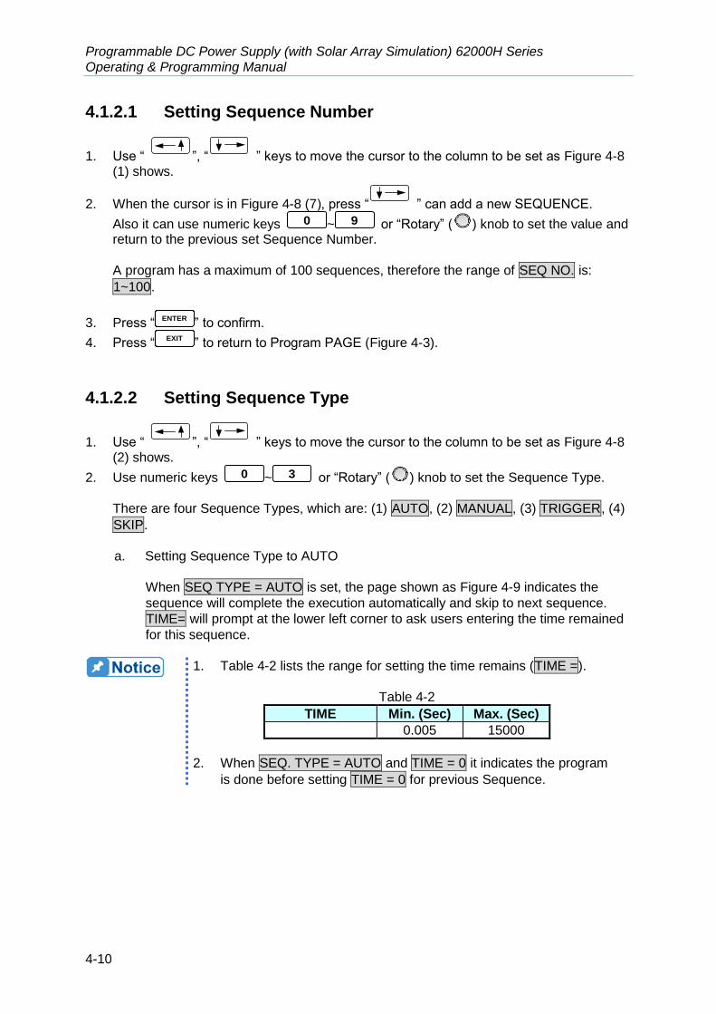
Programmable DC Power Supply (with Solar Array Simulation) 62000H Series Operating & Programming Manual
4-10
4.1.2.1 Setting Sequence Number
1. Use “ ”, “ ” keys to move the cursor to the column to be set as Figure 4-8 (1) shows.
2. When the cursor is in Figure 4-8 (7), press “ ” can add a new SEQUENCE.
Also it can use numeric keys 0 ~ 9 or “Rotary” (
) knob to set the value and return to the previous set Sequence Number.
A program has a maximum of 100 sequences, therefore the range of SEQ NO. is:
1~100.
3. Press “ENTER
” to confirm.
4. Press “EXIT
” to return to Program PAGE (Figure 4-3).
4.1.2.2 Setting Sequence Type
1. Use “ ”, “ ” keys to move the cursor to the column to be set as Figure 4-8 (2) shows.
2. Use numeric keys 0 ~ 3 or “Rotary” (
) knob to set the Sequence Type.
There are four Sequence Types, which are: (1) AUTO, (2) MANUAL, (3) TRIGGER, (4)
SKIP.
a. Setting Sequence Type to AUTO
When SEQ TYPE = AUTO is set, the page shown as Figure 4-9 indicates the
sequence will complete the execution automatically and skip to next sequence.
TIME= will prompt at the lower left corner to ask users entering the time remained
for this sequence.
1. Table 4-2 lists the range for setting the time remains (TIME =).
Table 4-2
TIME Min. (Sec) Max. (Sec)
0.005 15000
2. When SEQ. TYPE = AUTO and TIME = 0 it indicates the program
is done before setting TIME = 0 for previous Sequence.
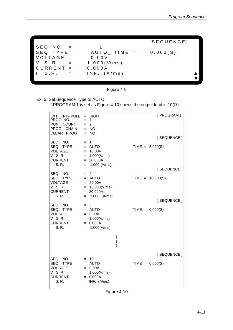
Program Sequence
4-11
[ S E Q U E N C E ]
S E Q N O = 1
S E Q T Y P E = A U T O _ T I M E = 0 . 0 0 0 ( S )
V O L T A G E = 0 . 0 0 V
V S . R . = 1 . 0 0 0 ( V/ m s )
C U R R E N T = 0 . 0 0 0 A
I S . R . = I N F . ( A / m s ) ▲
▼
Figure 4-9
Ex. 5: Set Sequence Type to AUTO
If PROGRAM 1 is set as Figure 4-10 shows the output load is 10().
[ PROGRAM ]
PROG NO. = 1
RUN COUNT = 2
PROG CHAIN = NO
CLEAR PROG = NO
[ SEQUENCE ]
SEQ NO. = 1
SEQ TYPE = AUTO TIME = 5.000(S)
VOLTAGE = 10.00V
V S. R. = 1.000(V/ms)
CURRENT = 20.000A
I S. R. = 1.000 (A/ms)
[ SEQUENCE ]
SEQ NO. = 2
SEQ TYPE = AUTO TIME = 10.000(S)
VOLTAGE = 30.00V
V S. R. = 10.000(V/ms)
CURRENT = 20.000A
I S. R. = 1.000 (A/ms)
[ SEQUENCE ]
SEQ NO. = 3
SEQ TYPE = AUTO TIME = 0.000(S)
VOLTAGE = 0.00V
V S. R. = 1.000(V/ms)
CURRENT = 0.000A
I S. R. = 1.000(A/ms)
↓
↓
↓
[ SEQUENCE ]
SEQ NO. = 10
SEQ TYPE = AUTO TIME = 0.000(S)
VOLTAGE = 0.00V
V S. R. = 1.000(V/ms)
CURRENT = 0.000A
I S. R. = INF. (A/ms)
EXT._TRIG PULL = HIGH
Figure 4-10
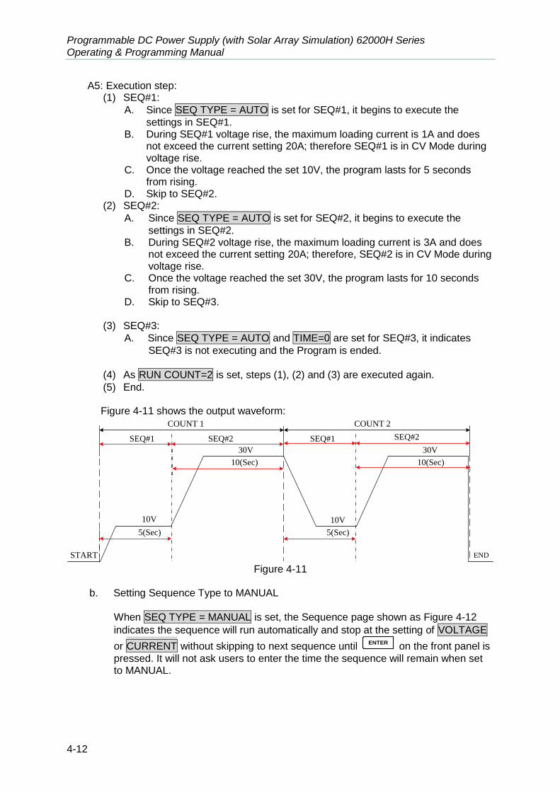
Programmable DC Power Supply (with Solar Array Simulation) 62000H Series Operating & Programming Manual
4-12
A5: Execution step: (1) SEQ#1:
A. Since SEQ TYPE = AUTO is set for SEQ#1, it begins to execute the
settings in SEQ#1. B. During SEQ#1 voltage rise, the maximum loading current is 1A and does
not exceed the current setting 20A; therefore SEQ#1 is in CV Mode during voltage rise.
C. Once the voltage reached the set 10V, the program lasts for 5 seconds from rising.
D. Skip to SEQ#2. (2) SEQ#2:
A. Since SEQ TYPE = AUTO is set for SEQ#2, it begins to execute the
settings in SEQ#2. B. During SEQ#2 voltage rise, the maximum loading current is 3A and does
not exceed the current setting 20A; therefore, SEQ#2 is in CV Mode during voltage rise.
C. Once the voltage reached the set 30V, the program lasts for 10 seconds from rising.
D. Skip to SEQ#3.
(3) SEQ#3:
A. Since SEQ TYPE = AUTO and TIME=0 are set for SEQ#3, it indicates
SEQ#3 is not executing and the Program is ended.
(4) As RUN COUNT=2 is set, steps (1), (2) and (3) are executed again.
(5) End.
Figure 4-11 shows the output waveform: COUNT 1 COUNT 2
SEQ#1 SEQ#2 SEQ#1 SEQ#2
START END
10V
30V
10V
30V
5(Sec) 5(Sec)
10(Sec) 10(Sec)
Figure 4-11
b. Setting Sequence Type to MANUAL
When SEQ TYPE = MANUAL is set, the Sequence page shown as Figure 4-12
indicates the sequence will run automatically and stop at the setting of VOLTAGE
or CURRENT without skipping to next sequence until ENTER
on the front panel is
pressed. It will not ask users to enter the time the sequence will remain when set to MANUAL.

Program Sequence
4-13
[ S E Q U E N C E ]
S E Q N O = 1
S E Q T Y P E = M A N U A L _
V O L T A G E = 0 . 0 0 V
V S . R . = 1 . 0 0 0 ( V/ m s )
C U R R E N T = 0 . 0 0 0 A
I S . R . = I N F . ( A / m s ) ▲
▼
Figure 4-12
c. Setting Sequence Type to TRIGGER
When SEQ TYPE = TRIGGER is set, the Sequence page shows as Figure 4-13
indicates the sequence will run automatically and stop at the setting of VOLTAGE
or CURRENT without skipping to next sequence until inputting a sine wave
(positive edge triggered TTL level) from PIN 8 of Analog Interface on the rear panel. See the descriptions in section 4.1.1.1 for the definition of PIN 8 input signal for Analog interface. It will not ask users to enter the time the sequence will remain when set to TRIGGER.
[ S E Q U E N C E ]
S E Q N O = 1
S E Q T Y P E = T R I G G E R _
V O L T A G E = 0 . 0 0 V
V S . R . = 1 . 0 0 0 ( V/ m s )
C U R R E N T = 0 . 0 0 0 A
I S . R . = I N F . ( A / m s ) ▲
▼
Figure 4-13
d. Set Sequence Type to SKIP
When SEQ TYPE = SKIP is set, the Sequence page shows as Figure 4-14
indicates the Sequence will skip automatically and jump to next SEQUENCE. This Sequence page will not ask users to enter the time sustained for this Sequence.
[ S E Q U E N C E ]
S E Q N O = 1
S E Q T Y P E = S K I P _
V O L T A G E = 0 . 0 0 V
V S . R . = 1 . 0 0 0 ( V/ m s )
C U R R E N T = 0 . 0 0 0 A
I S . R . = I N F . ( A / m s ) ▲
▼
Figure 4-14
Programmable DC Power Supply (with Solar Array Simulation) 62000H Series Operating & Programming Manual
4-14
4.1.2.3 Setting Time
1. Use “ ”, “ ” keys to move the cursor to the column to be set as Figure 4-8 (3) shows.
2. Use numeric keys 0 ~ 9 or “Rotary” (
) to set the value. This function is to set the time sustained. This setting TIME = only appears when SEQ.
TYPE = AUTO.
3. Press “ENTER
” to confirm.
4. Press “EXIT
” to return to Program PAGE (Figure 4-3).
4.1.2.4 Setting Voltage
1. Use “ ”, “ ” keys to move the cursor to the column to be set as Figure 4-8 (4) shows.
2. Use numeric keys 0 ~ 9 or “Rotary” (
) knob to set the SEQ output voltage
3. Press “ENTER
” to confirm.
4. Press “EXIT
” to return to Program PAGE (Figure 4-3). See section 3.2 for detail description.
4.1.2.5 Setting Voltage Slew Rate
1. Use “ ”, “ ” keys to move the cursor to the column to be set as Figure 4-8 (5) shows.
2. Use numeric keys 0 ~ 9 or “Rotary” (
) knob to set the SEQ voltage conversion slew rate.
3. Press “ENTER
” to confirm.
4. Press “EXIT
” to return to Program PAGE (Figure 4-3). See section 3.3.2.3 for detail description.
4.1.2.6 Setting Current
1. Use “ ”, “ ” keys to move the cursor to the column to be set as Figure 4-8 (6) shows.
2. Use numeric keys 0 ~ 9 or “Rotary” (
) knob to set the SEQ output current limit.
3. Press “ENTER
” to confirm.
4. Press “EXIT
” to return to Program PAGE (Figure 4-3). See section 3.2 for detail description.
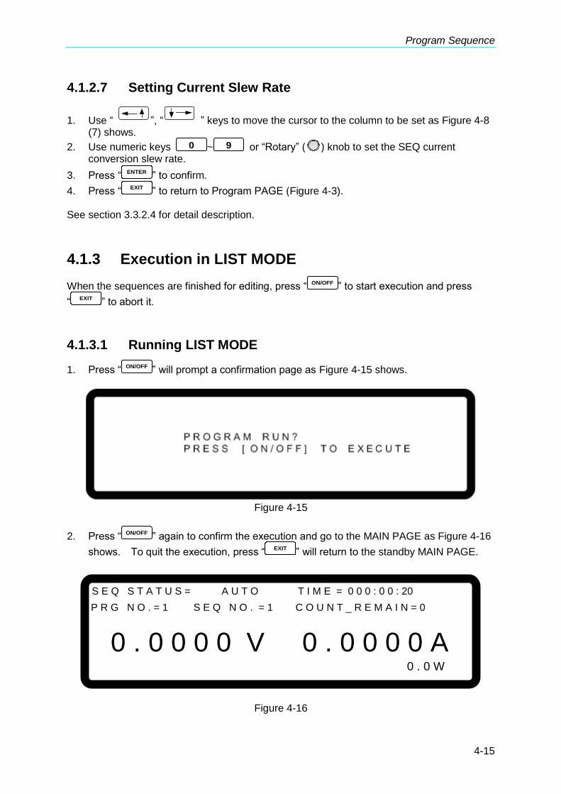
Program Sequence
4-15
4.1.2.7 Setting Current Slew Rate
1. Use “ ”, “ ” keys to move the cursor to the column to be set as Figure 4-8 (7) shows.
2. Use numeric keys 0 ~ 9 or “Rotary” (
) knob to set the SEQ current conversion slew rate.
3. Press “ENTER
” to confirm.
4. Press “EXIT
” to return to Program PAGE (Figure 4-3). See section 3.3.2.4 for detail description.
4.1.3 Execution in LIST MODE
When the sequences are finished for editing, press “ ON/OFF ” to start execution and press
“EXIT
” to abort it.
4.1.3.1 Running LIST MODE
1. Press “ ON/OFF ” will prompt a confirmation page as Figure 4-15 shows.
Figure 4-15
2. Press “ON/OFF
” again to confirm the execution and go to the MAIN PAGE as Figure 4-16
shows. To quit the execution, press “EXIT
” will return to the standby MAIN PAGE.
S E Q S T A T U S = A U T O T I M E = 0 0 0 : 0 0 : 20
P R G N O . = 1 S E Q N O . = 1 C O U N T _ R E M A I N = 0
0 . 0 0 0 0 V 0 . 0 0 0 0 A 0 . 0 W
Figure 4-16

Programmable DC Power Supply (with Solar Array Simulation) 62000H Series Operating & Programming Manual
4-16
1. Press “ ON/OFF ” in Program page (Figure 4-3) or Sequence page (Figure 4-8) will prompt a confirmation page as Figure 4-15 shows.
2. Press “EXIT
” to abort the executing program which means to stop the Power Supply from output.
4.1.3.2 Program List Mode Description
Figure 4-17 shows the main execution page of LIST MODE. Items (1)~(5) in the figure are explained below.
S E Q S T A T U S = A U T O T I M E = 0 0 0 : 0 0 : 20
P R G N O . = 1 S E Q N O . = 1 C O U N T _ R E M A I N = 0
0 . 0 0 0 0 V 0 . 0 0 0 0 A 0 . 0 W
( 1 ) ( 2 )
( 3 )
( 4 )
( 5 )
Figure 4-17
(1) Program Number: PRG NO. indicates the Program Number being executed at present.
(2) Sequence Number: SEQ NO. indicates the Sequence Number being executed at
present.
(3) Sequence Status: SEQ STATUS indicates the Sequence state being executed at
present.
(4) Count_Remain: COUNT_REMAIN indicates the numbers to be executed for the current
Program.
(5) Running Time: TIME indicates the sum of time from when the program is executed to the
sequence is run on Main Page.
The time format is HOUR:MIN:SEC and the maximum display limit is 99 hours 59 minutes
and 59 seconds. If the time accumulated exceeds the maximum display limit, it will reset to 0 and recount.
4.2 V_STEP MODE
One is able to set a run time program in V_STEP MODE. Figure 4-18 shows the screen
when V_STEP MODE is selected.

Program Sequence
4-17
[ P R O G R A M / S T E P]
S T A R T _ V O L T A G E = 0 . 0 0 V
E N D _ V O L T A G E = 0 . 0 0 V
R U N _ T I M E = 0 : 0 : 0 . 0 0
▼
Figure 4-18
4.2.1 Setting V_STEP MODE
V_STEP MODE has 3 settings: (1) START_VOLTAGE, (2) END_VOLTAGE and (3)
RUN_TIME.
4.2.1.1 Setting START_VOLTAGE
1. Use “ ”, “ ” keys to move the cursor to the column to be set as Figure 4-19 (1) shows. Set the start voltage of STEP MODE.
2. Use numeric keys 0 ~ 9 or “Rotary” (
) knob to set the value.
3. Press “ENTER
” to confirm.
4. Press “EXIT
” to return to Figure 4-1.
[ P R O G R A M / S T E P]
S T A R T _ V O L T A G E = 0 . 0 0 _ V
E N D _ V O L T A G E = 0 . 0 0 V
R U N _ T I M E = 0 : 0 : 0 . 0 0
▼
( 1 )
( 2 )
( 3 )
Figure 4-19
CAUTION The initial voltage of the hardware does not equal to the setting of the START_VOLTAGE. There are two circumstances that may occur in V_STEP MODE: (1) The output voltage rises to the setting of START_VOLTAGE and the V SLEW RATE is 1V/mS, or (2) it falls to the setting of START_VOLTAGE and the falling time is calculated by 1V/mS while the actual V SLEW RATE is varied by load.

Programmable DC Power Supply (with Solar Array Simulation) 62000H Series Operating & Programming Manual
4-18
4.2.1.2 Setting END_VOLTAGE
1. Use “ ”, “ ” keys to move the cursor to the column to be set as Figure 4-19 (2) shows. Set the end voltage of STEP MODE.
2. Use numeric keys 0 ~ 9 or “Rotary” (
) knob to set the value.
3. Press “ENTER
” to confirm.
4. Press “EXIT
” to return to Figure 4-1.
4.2.1.3 Setting RUN_TIME
1. Use “ ”, “ ” keys to move the cursor to the column to be set as Figure
4-19(3) shows. Set the run time of STEP MODE. The time format is HOUR:MIN:SEC
and the maximum setting is 99 hours 59 minutes and 59.99 seconds.
2. Use the numeric keys 0 ~ 9 or “Rotary” (
) knob to set the value.
3. Press “ENTER
” to confirm.
4. Press “EXIT
” to return to Figure 4-1.
When V_STEP MODE ends the hardware output voltage will remain at the setting of END_VOLTAGE.
Ex. 1: Set the START_VOLTAGE to 10V, END_VOLTAGE to 50V and RUN_TIME to 10
minutes.
CASE1: The hardware initial voltage is 0V and the output waveform is as Figure 4-20 shows.
CASE2: The hardware initial voltage is 10V and the output waveform is as Figure 4-21 shows.
CASE3: The hardware initial voltage is 20V and the output waveform is as Figure 4-22 shows.
START
10(MIN)
50V
0V
10V
1V/mS
Figure 4-20
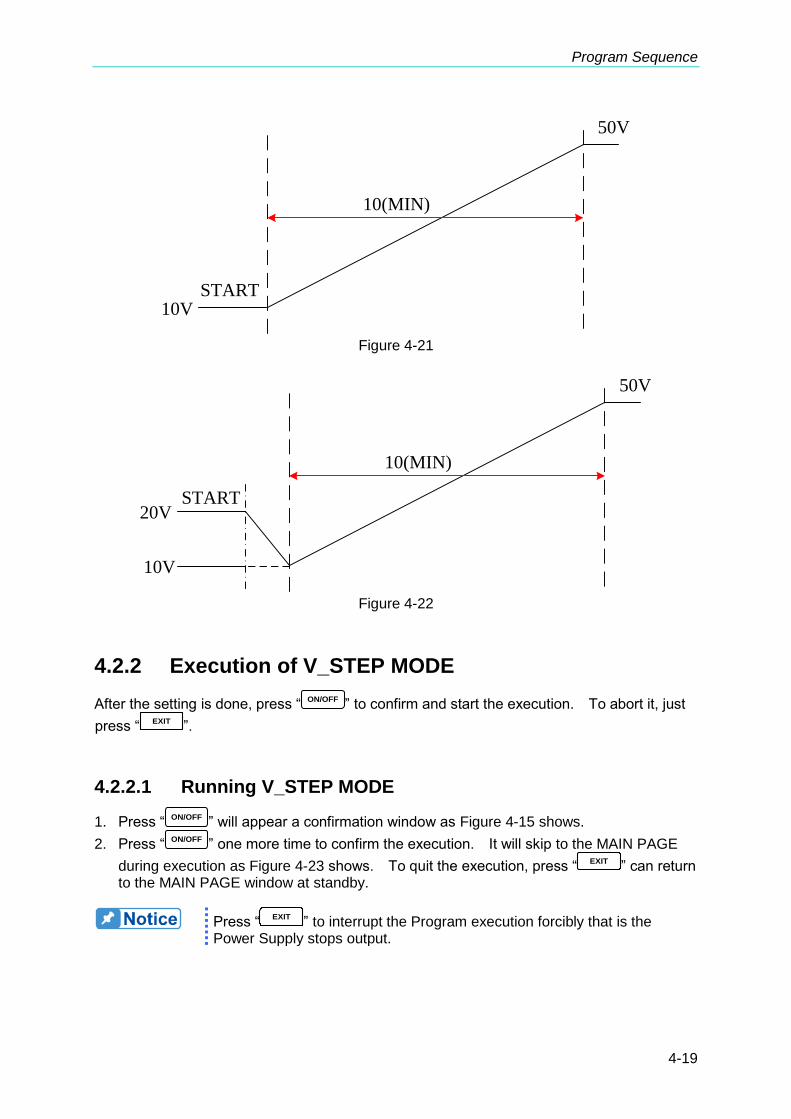
Program Sequence
4-19
START
10(MIN)
50V
10V
Figure 4-21
START
10(MIN)
50V
20V
10V
Figure 4-22
4.2.2 Execution of V_STEP MODE
After the setting is done, press “ ON/OFF ” to confirm and start the execution. To abort it, just
press “EXIT
”.
4.2.2.1 Running V_STEP MODE
1. Press “ ON/OFF ” will appear a confirmation window as Figure 4-15 shows.
2. Press “ON/OFF
” one more time to confirm the execution. It will skip to the MAIN PAGE
during execution as Figure 4-23 shows. To quit the execution, press “EXIT
” can return to the MAIN PAGE window at standby.
Press “EXIT
” to interrupt the Program execution forcibly that is the Power Supply stops output.
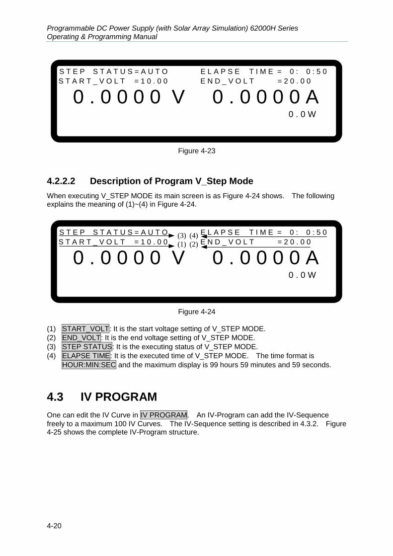
Programmable DC Power Supply (with Solar Array Simulation) 62000H Series Operating & Programming Manual
4-20
S T E P S T A T U S = A U T O E L A P S E T I M E = 0 : 0 : 5 0
S T A R T _ V O L T = 1 0 . 0 0 E N D _ V O L T = 2 0 . 0 0
0 . 0 0 0 0 V 0 . 0 0 0 0 A 0 . 0 W
Figure 4-23
4.2.2.2 Description of Program V_Step Mode
When executing V_STEP MODE its main screen is as Figure 4-24 shows. The following explains the meaning of (1)~(4) in Figure 4-24.
S T E P S T A T U S = A U T O E L A P S E T I M E = 0 : 0 : 5 0
S T A R T _ V O L T = 1 0 . 0 0 E N D _ V O L T = 2 0 . 0 0
0 . 0 0 0 0 V 0 . 0 0 0 0 A 0 . 0 W
(3) (4)
(1) (2)
Figure 4-24
(1) START_VOLT: It is the start voltage setting of V_STEP MODE.
(2) END_VOLT: It is the end voltage setting of V_STEP MODE.
(3) STEP STATUS: It is the executing status of V_STEP MODE.
(4) ELAPSE TIME: It is the executed time of V_STEP MODE. The time format is
HOUR:MIN:SEC and the maximum display is 99 hours 59 minutes and 59 seconds.
4.3 IV PROGRAM
One can edit the IV Curve in IV PROGRAM. An IV-Program can add the IV-Sequence
freely to a maximum 100 IV Curves. The IV-Sequence setting is described in 4.3.2. Figure 4-25 shows the complete IV-Program structure.

Program Sequence
4-21
[ IV-PROGRAM ]
PROG NO. = 1
RUN COUNT = 1
PROG CHAIN = NO
CLEAR PROG = NO
[ IV-SEQUENCE ]
SEQ NO. = 1
IV-FILE NO. = 0
SEQ TYPE = AUTO
TIME = 0 (S)
[ IV-SEQUENCE ]
SEQ NO. = 2
IV-FILE NO. = 0
SEQ TYPE = AUTO
TIME = 0 (S)
[ IV-SEQUENCE ]
SEQ NO. = 3
IV-FILE NO. = 0
SEQ TYPE = AUTO
TIME = 0 (S)
↓
↓
↓
Figure 4-25
4.3.1 Setting IV-PROGRAM
There are 4 items in IV-PROGRAM including (1) PROG NO., (2) RUN COUNT, (3) PROG
CHAIN and (4) CLEAR PROG as Figure 4-26 shows. See section 4.1.1.2 to 4.1.1.5 for the
detail of setting these 4 parameters.
[ I V - P R O G R A M ]
P R O G N O . = 1 _
R U N C O U N T = 1
P R O G C H A I N = N O
C L E A R P R O G = N O
▼
( 1 )( 2 )( 3 )
( 4 )
Figure 4-26

Programmable DC Power Supply (with Solar Array Simulation) 62000H Series Operating & Programming Manual
4-22
4.3.2 Setting IV-Sequence
1. The number of default IV-SEQUENCE in an IV-PROGRAM is 0 and each IV-PROGRAM can add IV-SEQUENCE freely to 100 sequences in total. In other words, the sum of IV-SEQUENCE set in the total 10 IV-PROGRAMS is 100 maximum.
2. To add a new IV-SEQUENCE:
a. In an IV-PROGRAM page (Figure 4-26), when the cursor is at (4) of Figure 4-26,
press “ ” to add the first IV-SEQUENCE if there is no IV-SEQUENCE in the IV-PROGRAM and the screen will appear as Figure 4-27 shows.
b. In an IV-SEQUENCE page (Figure 4-27) under an IV-PROGRAM, when the cursor
is at (4) of Figure 4-27, press “ ” to add another new IV-SEQUENCE.
The “ ” key is often used as the direction key and only used to add new IV-SEQUENCE in the above two conditions.
3. Use “ ”, “ ” keys to move the cursor to the column to be set as Figure 4-27 shows.
[ I V- S E Q U E N C E ]
S E Q N O. = 1 _
I V – F I L E N O. = 0
S E Q T Y P E = A U T O
T I M E = 0 ( S )
▲ ▼
( 1 )
( 2 )
( 4 )
( 3 )
Figure 4-27
4. Use the numeric keys 0 ~ 9 or “Rotary” (
) knob to set the value. Each IV-Sequence can set the following 4 items: (1) SEQ NO., (2) IV-FILE NO., (3)
SEQ. TYPE and (4) TIME. They are explained the following sections.
5. Press “ENTER
” to confirm.
6. Press “EXIT
” to return to IV-Program Page (Figure 4-26).
4.3.2.1 Setting Sequence Number
1. Use “ ”, “ ” keys to move the cursor to the column to be set as Figure 4-27 (1) shows.
2. When the cursor is at Figure 4-27 (4), press “ ” to add a new IV-SEQUENCE. It
can also use the numeric keys 0 ~ 9 or “Rotary” (
) knob to enter the
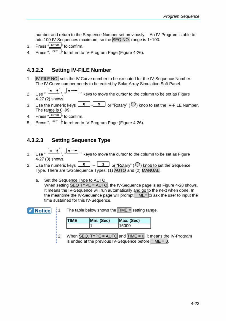
Program Sequence
4-23
number and return to the Sequence Number set previously. An IV-Program is able to
add 100 IV-Sequences maximum, so the SEQ NO. range is 1~100.
3. Press “ENTER
” to confirm.
4. Press “EXIT
” to return to IV-Program Page (Figure 4-26).
4.3.2.2 Setting IV-FILE Number
1. IV-FILE NO. sets the IV Curve number to be executed for the IV-Sequence Number.
The IV Curve number needs to be edited by Solar Array Simulation Soft Panel.
2. Use “ ”, “ ” keys to move the cursor to the column to be set as Figure 4-27 (2) shows.
3. Use the numeric keys 0 ~ 9 or “Rotary” (
) knob to set the IV-FILE Number. The range is 0~99.
4. Press “ENTER
” to confirm.
5. Press “EXIT
” to return to IV-Program Page (Figure 4-26).
4.3.2.3 Setting Sequence Type
1. Use “ ”, “ ” keys to move the cursor to the column to be set as Figure 4-27 (3) shows.
2. Use the numeric keys 0 ~ 1 or “Rotary” (
) knob to set the Sequence
Type. There are two Sequence Types: (1) AUTO and (2) MANUAL.
a. Set the Sequence Type to AUTO
When setting SEQ TYPE = AUTO, the IV-Sequence page is as Figure 4-28 shows.
It means the IV-Sequence will run automatically and go to the next when done. In
the meantime the IV-Sequence page will prompt TIME= to ask the user to input the
time sustained for this IV-Sequence.
1. The table below shows the TIME = setting range.
TIME Min. (Sec) Max. (Sec)
1 15000
2. When SEQ. TYPE = AUTO and TIME = 0, it means the IV-Program
is ended at the previous IV-Sequence before TIME = 0.

Programmable DC Power Supply (with Solar Array Simulation) 62000H Series Operating & Programming Manual
4-24
[ I V- S E Q U E N C E ]
S E Q N O. = 1
I V – F I L E N O. = 0
S E Q T Y P E = A U T O _
T I M E = 0 ( S )
▲ ▼
Figure 4-28
b. Set the Sequence Type to MANUAL
When set SEQ TYPE = MANUAL, the IV-Sequence page is as Figure 4-29 shows.
It means the IV-Sequence will run automatically and stops at the IV-FILE Number
set in the IV-Sequence, also it will not go to the next IV-Sequence until the “ENTER
” on the front panel is pressed. The IV-Sequence page will not ask the user to enter
the sustained time when SEQ TYPE =MANUAL.
[ I V- S E Q U E N C E ]
S E Q N O. = 1
I V – F I L E N O. = 0
S E Q T Y P E = M A N U A L _
▲ ▼
Figure 4-29
3. Press “ENTER
” to confirm.
4. Press “EXIT
” to return to IV-Program Page (Figure 4-26)。
4.3.2.4 Setting Time
1. Use “ ”, “ ” keys to move the cursor to the column to be set as Figure
4-27 (4) shows.
2. Use the numeric keys 0 ~ 9 or “Rotary” (
) knob to set the value. This function is to set the time sustained for IV-Sequence. TIME = only appears to ask
for an input when SEQ. TYPE = AUTO.
3. Press “ENTER
” to confirm.
4. Press “EXIT
” to return to IV-Program Page (Figure 4-26).
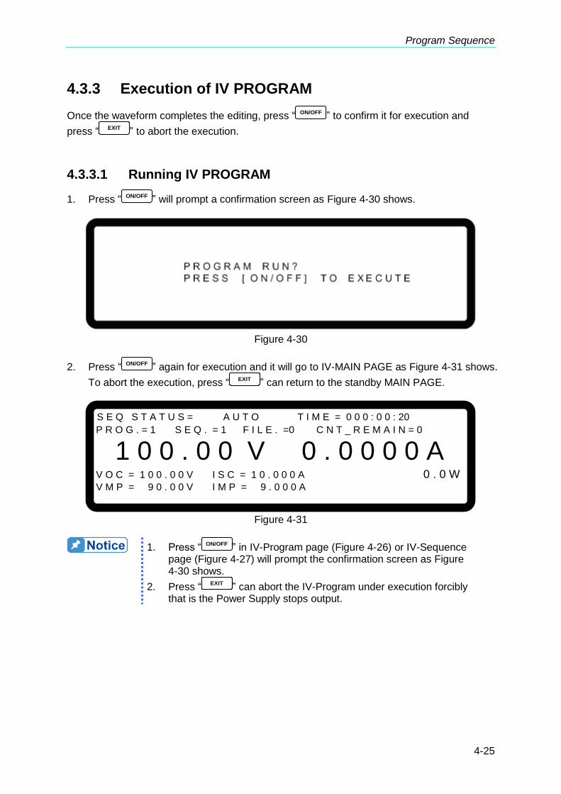
Program Sequence
4-25
4.3.3 Execution of IV PROGRAM
Once the waveform completes the editing, press “ ON/OFF ” to confirm it for execution and
press “EXIT
” to abort the execution.
4.3.3.1 Running IV PROGRAM
1. Press “ ON/OFF ” will prompt a confirmation screen as Figure 4-30 shows.
Figure 4-30
2. Press “ ON/OFF ” again for execution and it will go to IV-MAIN PAGE as Figure 4-31 shows.
To abort the execution, press “EXIT
” can return to the standby MAIN PAGE.
S E Q S T A T U S = A U T O T I M E = 0 0 0 : 0 0 : 20
P R O G . = 1 S E Q . = 1 F I L E . =0 C N T _ R E M A I N = 0
1 0 0 . 0 0 V 0 . 0 0 0 0 A V O C = 1 0 0 . 0 0 V I S C = 1 0 . 0 0 0 A 0 . 0 W V M P = 9 0 . 0 0 V I M P = 9 . 0 0 0 A
Figure 4-31
1. Press “ON/OFF
” in IV-Program page (Figure 4-26) or IV-Sequence page (Figure 4-27) will prompt the confirmation screen as Figure 4-30 shows.
2. Press “EXIT
” can abort the IV-Program under execution forcibly that is the Power Supply stops output.

Programmable DC Power Supply (with Solar Array Simulation) 62000H Series Operating & Programming Manual
4-26
4.3.3.2 IV Program Main Screen
When the IV PROGRAM is running the main screen will appear as Figure 4-32 shows. The definitions of items (1) ~ (10) in Figure 4-32 are explained below.
S E Q S T A T U S = A U T O T I M E = 0 0 0 : 0 0 : 20
P R O G . = 1 S E Q . = 1 F I L E . =0 C N T _ R E M A I N = 0
1 0 0 . 0 0 V 0 . 0 0 0 0 A V O C = 1 0 0 . 0 0 V I S C = 1 0 . 0 0 0 A 0 . 0 W V M P = 9 0 . 0 0 V I M P = 9 . 0 0 0 A
( 1 ) ( 2 )( 3 ) ( 4 ) ( 5 ) ( 6 )
( 7 ) ( 8 )
( 9 ) ( 10 )
Figure 4-32
(1) IV-Sequence status: SEQ STATUS shows the IV-Sequence status currently running.
(2) Total Time accumulated: TIME shows the total time accumulated from the execution of
IV-PROGRAM to the IV-Sequence on IV-Main Page. The time format is
HOUR:MIN:SEC and the maximum time display is 99 hours 59 minutes and 59 seconds.
If the accumulated time exceeds the maximum time display, it will reset to zero and re-accumulate.
(3) IV-Program Number: PROG. shows the IV-Program Number executed at present.
(4) IV-Sequence Number: SEQ. shows the IV-Sequence Number executed at present.
(5) IV-FILE Number: FILE. shows the IV-FILE Number executed at present.
(6) Count_Remain : CNT_REMAIN shows the count of IV-Program to be executed.
(7) Open Circuit Voltage: VOC shows the open circuit voltage of the IV-FILE Number
executed at present
(8) Short Circuit Current: ISC shows the short circuit current of the IV-FILE Number
executed at present.
(9) Max. Power Voltage: VMP shows the maximum power voltage of the IV-FILE Number
executed at present.
(10) Max. Power Current: IMP shows the maximum power current of the IV-FILE Number
executed at present.

Remote Operation
5-1
5. Remote Operation
5.1 Overview
62000H Series DC Power Supply can be controlled remotely via USB, GPIB, Ethernet, RS-232 or RS-485 port. The USB interface supports USB 2.0/USB 1.1. GPIB interface is an 8-bit parallel data bus that synchronizes with the host bus commands. Ethernet interface is used in local area network for data transmission. RS-232C is a serial bus with less powerful functions; however, users can do remote control easily via simple programming.
5.1.1 USB Interface
(1) Hardware Support: USB 2.0 and USB 1.1 (2) Software Support: USBTMC class and USB488 subclass (3) OS Support: Windows 98/2000/XP/Vista/Windows 7/Windows 8 (4) Installing Driver: 62000H Series USB Interface supports USBTMC, so if the PC
OS supports USBTMC (installed NI-VISA runtime version 3.00 or above) it is no need to install other drivers. The OS will search for the standard USBTMC driver installation program automatically.
If the PC OS does not support USBTMC, it is suggested to install the NI-VISA runtime version 3.00 or above first. When the installation of NI-VISA runtime is done, the USBTMC driver program is stored in OS. The PC can communicate with 62000H Series via NI-VISA after using the USB cable to connect them. Related Documents: 1. USB Test and Measurement Class (USBTMC) specification, Revision 1.0,
http://www.usb.org 2. USB Test and Measurement Class USB488 subclass specification, Revision 1.0,
http://www.usb.org
5.1.2 Setting GPIB, Ethernet, RS-232C & RS-485
Parameters
See section 3.3.8.
5.1.3 Connecting RS-232C
The default baudrate of 62000H Series DC Power Supply is 115200 and the parity check is set to None. Only TxD and RxD signal can be used for data transmission. The connector of RS-232C is a 9-pin D type male connector. Table 5-1 lists the pins and signals of RS-232C connector.
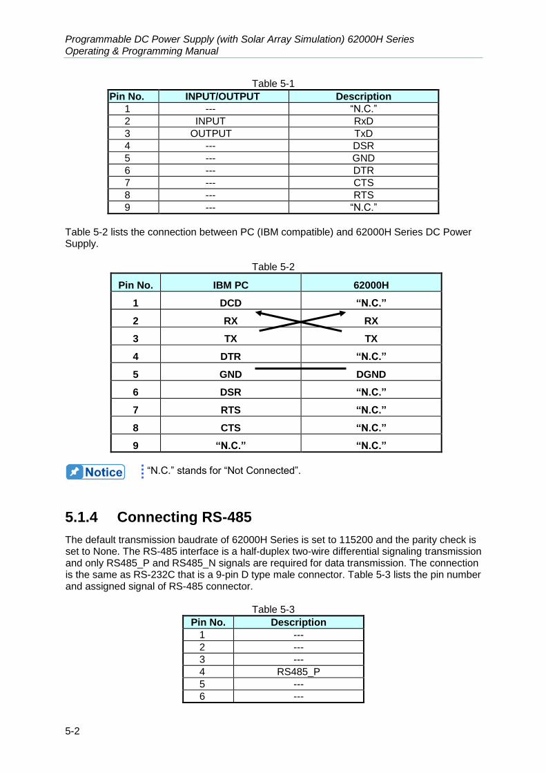
Programmable DC Power Supply (with Solar Array Simulation) 62000H Series Operating & Programming Manual
5-2
Table 5-1
Pin No. INPUT/OUTPUT Description
1 --- “N.C.”
2 INPUT RxD
3 OUTPUT TxD
4 --- DSR
5 --- GND
6 --- DTR
7 --- CTS
8 --- RTS
9 --- “N.C.”
Table 5-2 lists the connection between PC (IBM compatible) and 62000H Series DC Power Supply.
Table 5-2
Pin No. IBM PC 62000H
1 DCD “N.C.”
2 RX RX
3 TX TX
4 DTR “N.C.”
5 GND DGND
6 DSR “N.C.”
7 RTS “N.C.”
8 CTS “N.C.”
9 “N.C.” “N.C.”
“N.C.” stands for “Not Connected”.
5.1.4 Connecting RS-485
The default transmission baudrate of 62000H Series is set to 115200 and the parity check is set to None. The RS-485 interface is a half-duplex two-wire differential signaling transmission and only RS485_P and RS485_N signals are required for data transmission. The connection is the same as RS-232C that is a 9-pin D type male connector. Table 5-3 lists the pin number and assigned signal of RS-485 connector.
Table 5-3
Pin No. Description
1 ---
2 ---
3 ---
4 RS485_P
5 ---
6 ---

Remote Operation
5-3
7 ---
8 ---
9 RS485_N
Here is the connection:
5.1.5 Ethernet Remote Control
To use a PC with Ethernet to remote program a 62000H, the IP address, Gateway address and Subnet mask need to be learned before application. A unique IP address will be assigned to the Ethernet interface that connects to a device. The address enables the system controller to communicate with the individual device. To set the IP address of Chroma 62000H Series, just use the “REMOTE” setting in “CONFIG” menu. This section describes how to use the network interface rapidly and correctly. Be sure to read it clearly and carefully before using the 62000H network interface and ensure the network is connected firmly and correctly to the hardware before execution.
The transmission protocol of 62000HS Series remote control is TCP and communication port is 2101.
There are 4 setting procedures as the figure and description listed below.
Slave 1 (62000H)
Slave n (62000H)
Master (PC)
RS485_P RS485_N

Programmable DC Power Supply (with Solar Array Simulation) 62000H Series Operating & Programming Manual
5-4
5.1.5.1 Selecting the LAN to be Connected
The LAN is divided into Site LAN and Private LAN. Site LAN usually indicates the larger local area network such as Intranet that contains network server (DHCP, WINS, DNS, etc.), Terminator, Router, Firewall and Internet linkage as the figure shown below.
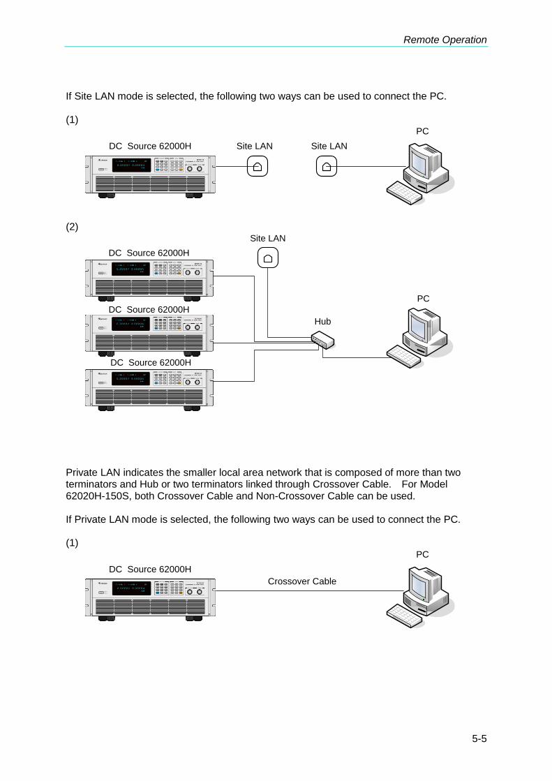
Remote Operation
5-5
If Site LAN mode is selected, the following two ways can be used to connect the PC. (1)
DC Source 62000H Site LAN Site LAN
PC
(2)
PC
DC Source 62000H
DC Source 62000H
DC Source 62000H
Site LAN
Hub
Private LAN indicates the smaller local area network that is composed of more than two terminators and Hub or two terminators linked through Crossover Cable. For Model 62020H-150S, both Crossover Cable and Non-Crossover Cable can be used. If Private LAN mode is selected, the following two ways can be used to connect the PC. (1)
DC Source 62000H
PC
Crossover Cable
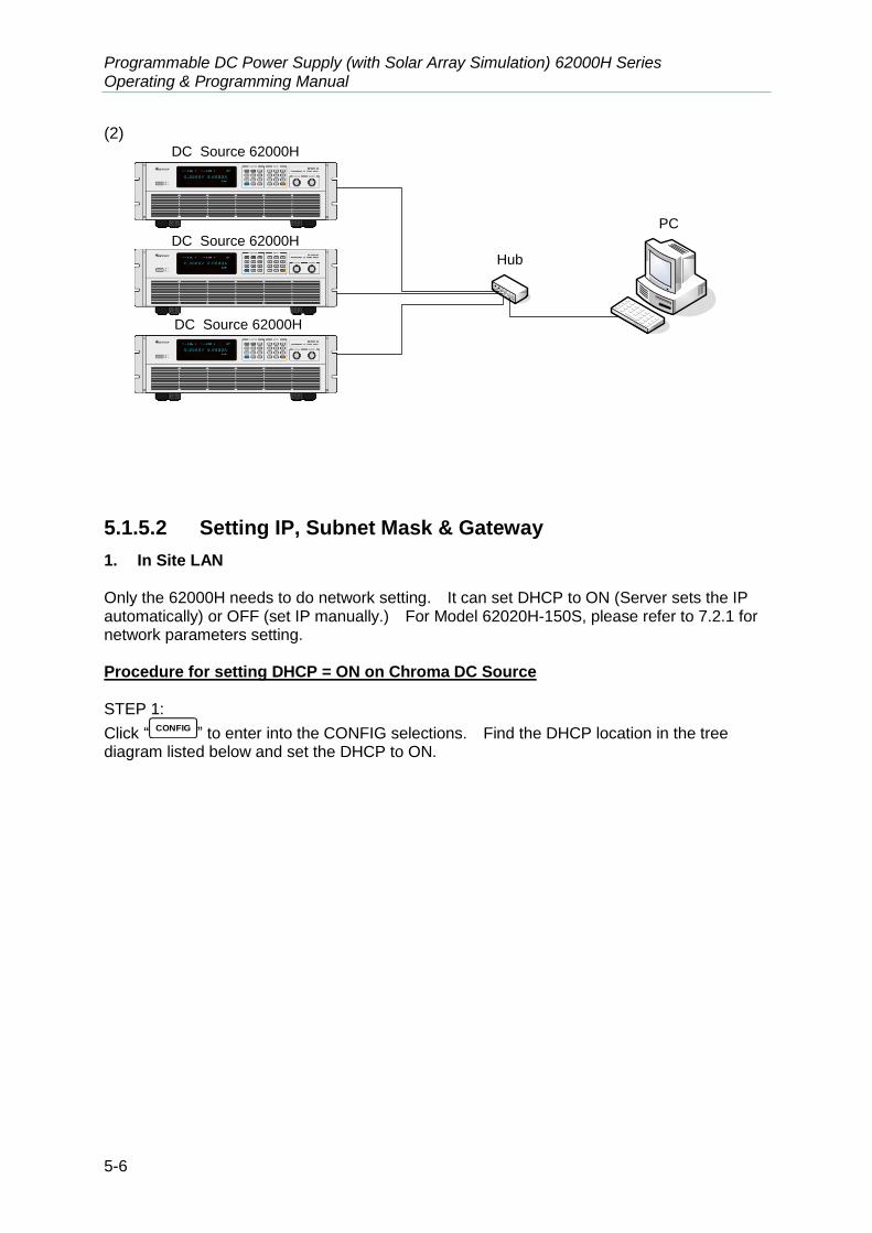
Programmable DC Power Supply (with Solar Array Simulation) 62000H Series Operating & Programming Manual
5-6
(2)
PC
DC Source 62000H
DC Source 62000H
DC Source 62000H
Hub
5.1.5.2 Setting IP, Subnet Mask & Gateway
1. In Site LAN Only the 62000H needs to do network setting. It can set DHCP to ON (Server sets the IP automatically) or OFF (set IP manually.) For Model 62020H-150S, please refer to 7.2.1 for network parameters setting. Procedure for setting DHCP = ON on Chroma DC Source STEP 1:
Click “CONFIG
” to enter into the CONFIG selections. Find the DHCP location in the tree diagram listed below and set the DHCP to ON.

Remote Operation
5-7
1. SYSTEM SETUP
2. OUTPUT SETUP
3. SERIES/PARALLEL
4.DISPLAY
5. PROTECTION
6.FACTORYSETTING
7. CALIBRATION
ETHERNET =
CONFIG
RS232/RS485
DHCP:ON
CONFIG PAGE
IP ADDRESS :XXX.XXX.XXX.XXX
GATEWAY ADDR:XXX.XXX.XXX.XXX
SUBNET MASK :XXX.XXX.XXX.XXX
APPLY=YES
BAUDRATE
8. REMOTE
GPIB ADDR
LAN Status
STEP 2:
Click downward to APPLY and set it to YES to confirm sending out the settings. STEP 3: The screen will show the network setting status with one of the messages listed below:

Programmable DC Power Supply (with Solar Array Simulation) 62000H Series Operating & Programming Manual
5-8
a. SETTING : The network card is setting.
b. CONNECTING : The network card is connecting.
c. NONE_CONNECT : The network is not connected.
d. CONNECTED : The network is connected.
e. MODULE_ERR : The network card setting is wrong.
When the setting is successful, the panel will update and show the network settings automatically and clear the status message. STEP 4: Save the settings and return to the panel main screen so that the 62000H will save the settings. Procedure for setting DHCP = OFF on Chroma DC Source 62000H STEP 1: It also needs to set the IP, GATEWAY and SUBNET MASK parameters when the DHCP=OFF. So, if the users know the Site LAN they are in, the settings should be done easily. If the users do not know the Site LAN they are in at the present, please contact the network administrator and request for setting the network parameter manually.
If the user knows the present network setting of PC, the settings of SUBNET MASK and GATEWAY can be input to 62000H directly. As to the IP Address, it can set one with the same domain but different IP to 62000H. For instance, the PC’s IP:10.1.7.100, Mask: 255.255.254.0, Gateway: 10.1.7.254, the user can set the IP:10.1.7.101, Mask: 255.255.254.0 and Gateeway:10.1.7.254 for 62000H. The premise is IP:10.1.7.101 is not being used by any other user.
STEP 2:
Click downward to APPLY and set it to YES to confirm sending out the settings. STEP 3: The screen will show the network setting status with one of the messages listed below:
a. SETTING : The network card is setting.
b. CONNECTING : The network card is connecting.
c. NONE_CONNECT : The network is not connected.
d. CONNECTED : The network is connected.
e. MODULE_ERR : The network card setting is wrong.
When the setting is successful, the panel will update and show the network settings automatically and clear the status message. STEP 4: Save the settings and return to the panel main screen so that the 62000H will save the settings.

Remote Operation
5-9
2. In Private LAN In common situation, the PC does not have a DHCP Server. So this sections only explains the procedures for setting DHCP=OFF. In Private LAN, the IP of all connected network devices need to be set manually, such as the PC is connected to 62000H through Crossover Cable so these two devices have to set the IP manually. For Model 62020H-150S, please refer to section 7.2.1 for network parameters setting. Procedure for setting DHCP = OFF on PC Ensure the local area network setting is to set the IP manually. If not, change it to assign IP manually and complete the other settings. STEP 1: Click [Control Panel] on the PC and click “Network Connections”.
STEP 2: Select “Local Area Connection” and right-click it to select the [Properties].
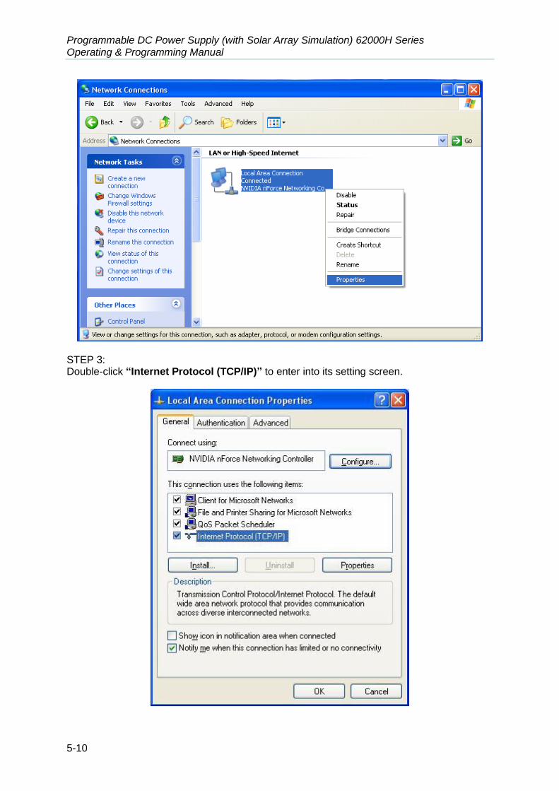
Programmable DC Power Supply (with Solar Array Simulation) 62000H Series Operating & Programming Manual
5-10
STEP 3: Double-click “Internet Protocol (TCP/IP)” to enter into its setting screen.

Remote Operation
5-11
STEP 4: Select “Use the following IP address” (that is to set the IP manually). Here the user has to plan the local area network desired.
STEP 5:
When the setting is done, click OK to return to previous level and click OK again to complete
the setting procedure. Procedure for setting DHCP = OFF on Chroma DC Source 62000H: STEP 1: It is required to set the IP, GATEWAY and SUBNET MASK parameters when the DHCP=OFF. If the user knows the present network setting of PC, the settings of SUBNET MASK and GATEWAY can be input to 62000H directly. As to the IP Address, it can set one with the same domain but different IP to 62000H. For instance, the PC’s IP:10.1.7.100, Mask: 255.255.254.0, Gateway: 10.1.7.254, the user can set the IP:10.1.7.101, Mask: 255.255.254.0 and Gateeway:10.1.7.254 for 62000H. The premise is IP:10.1.7.101 is not being used by any other user. STEP 2: Move the cursor to APPLY when the parameter setting is done and set it to YES to confirm sending out the settings. STEP 3: The screen will show the network setting status with one of the messages listed below:
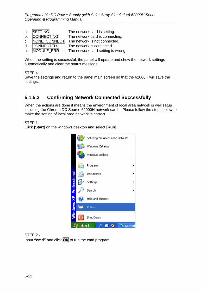
Programmable DC Power Supply (with Solar Array Simulation) 62000H Series Operating & Programming Manual
5-12
a. SETTING : The network card is setting.
b. CONNECTING : The network card is connecting.
c. NONE_CONNECT : The network is not connected.
d. CONNECTED : The network is connected.
e. MODULE_ERR : The network card setting is wrong.
When the setting is successful, the panel will update and show the network settings automatically and clear the status message. STEP 4: Save the settings and return to the panel main screen so that the 62000H will save the settings.
5.1.5.3 Confirming Network Connected Successfully
When the actions are done it means the environment of local area network is well setup including the Chroma DC Source 62000H network card. Please follow the steps below to make the setting of local area network is correct. STEP 1: Click [Start] on the windows desktop and select [Run].
STEP 2:
Input “cmd” and click OK to run the cmd program.

Remote Operation
5-13
STEP 3: If MS-DOS environment is opened in STEP2, it can input ping IP address directly, such as ping 10.1.6.209. If there is a response, it means the setting of local area network is done successfully.
5.1.5.4 Communicating with the Instrument
The user can use the NI-MAX (Measurement & Automation Explorer) application software of National Instruments or customized program to communicate with the user’s instrument. If using NI VISA, the user needs to open VISA Session Resource Name in the format of TCPIP0::<IP address>::2101::SOCKET, such as: TCPIP0::10.1.7.100:: 2101::SOCKET. If not using NI VISA then specify the TCP/IP SOCKET PORT to 2101. Following is the example of using NI-MAX (Measurement & Automation Explorer):
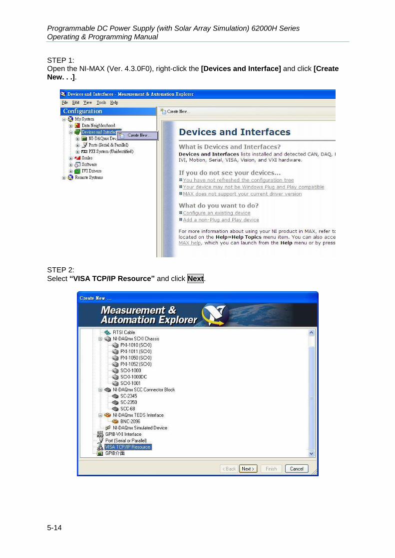
Programmable DC Power Supply (with Solar Array Simulation) 62000H Series Operating & Programming Manual
5-14
STEP 1: Open the NI-MAX (Ver. 4.3.0F0), right-click the [Devices and Interface] and click [Create New. . .].
STEP 2:
Select “VISA TCP/IP Resource” and click Next.

Remote Operation
5-15
STEP 3:
Select Raw Socket and click Next.
STEP 4: Input the IP Address and Port Number (the TCP/IP Port used by 62000H is 2101) and click Validate.

Programmable DC Power Supply (with Solar Array Simulation) 62000H Series Operating & Programming Manual
5-16
STEP 5: The following screen will appear if the connection is successful. Close this message and then
click Finish to end it.
STEP 6: A VISA TCP/IP Resource will be added to the Configuration list under Devices and Interfaces. Click it to open the VISA Session (NI VISA Ver. 3.0).

Remote Operation
5-17
STEP 7: Select Termination Char Enable for the Attribute Name in Property Node (Write) under “Template” tab. If the Current Value is set to VI_FALSE, please change the New Value to
VI_TRUE and click Execute.
STEP 8: Click “Basic I/O” tab and use Write to write in the command to 62000H (using *IDN? as the
example) and click Execute.

Programmable DC Power Supply (with Solar Array Simulation) 62000H Series Operating & Programming Manual
5-18
STEP 9:
Select “Basic I/O” tab and use Read to read back the 62000H status and click Execute.
5.2 GPIB Function of 62000H Series
Table 5-4
GPIB Function Description
Talker/Listener Commands and response messages can be sent and received over the GPIB bus. Status information can be read using a series poll.
Service Request It sets the SRQ line to true if there is an enabled service request condition.
Remote/Local Power-on in local mode, the front panel can be operated and the commands are responded through GPIB. When in remote mode,
all front panel keys are invalid exceptLOCAL
. Press “LOCAL
” can return to local mode.
5.3 Introduction to Programming
All commands and response messages are transmitted in ASCII codes. The response messages must be read completely before a new command is sent, or the remaining response messages will be lost and cause a query interrupt error.

Remote Operation
5-19
5.3.1 Conventions
The table below lists the convention used in this section.
Table 5-5
Angle brackets < > Items in angle brackets are parameter abbreviations.
Vertical bar | Vertical bar separates alternative parameters.
Square brackets
[ ] Items in square brackets are optional. For example, OUTP [ : STATe] means that : STATe may be omitted.
Braces { } Braces indicate the parameters that may be repeated. The notation <A> {<, B>} means that parameter “A” must be entered while parameter “B” may be omitted or entered once or more times.
5.3.2 Numerical Data Formats
The numerical data format of 62000H DC Power Supply is listed in Table 5-6.
Table 5-6 Format of Numerical Data
Symbol Description Example
NR1 It is a digit without decimal point. The decimal is assumed to be at the right of the least significant digit.
123, 0123
NR2 It is a digit with a decimal point. 12.3, .123
NR3 It is a digit with a decimal point and an exponent. 1.23E2
NRf Flexible decimal format including NR1or NR2 or NR3. 123, 12.3, .23E+3
NRf+ Extended decimal format including NRf and MIN, MAX. MIN and MAX is the high and low limit of parameter.
123, 12.3,1.23E+3, MIN, MAX
5.3.3 Boolean Data Format
The Boolean parameter <Boolean> uses the form ON|OFF only.
5.3.4 Character Data Format
The character strings returned by query command are shown in either of the following forms: <CRD> Character Response Data: character string with maximum length of 12. <SRD> String Response Data: character string.

Programmable DC Power Supply (with Solar Array Simulation) 62000H Series Operating & Programming Manual
5-20
5.3.5 Basic Definition
5.3.5.1 Command Tree Structure
The commands of the DC Power Supply are based on a hierarchical structure, also known as a tree system. In order to obtain a particular command, the full path to that command must be specified. This path is represented in the structure by placing the highest node in the farthest left position of the hierarchy. Lower nodes in the hierarchy are indented in the position to the right, below the parent node.
5.3.5.2 Program Headers
Program headers are key words that identify the command. They follow the syntax described in subsection 5.6 of IEEE 488.2. The DC Power Supply accepts characters in both upper and lower case without distinguishing the difference. Program headers consist of two distinctive types, common command headers and instrument-controlled headers.
5.3.5.3 Common Command and Query Headers
The syntax of common command and query headers is described in IEEE 488.2. It is used together with the IEEE 488.2 defined common commands and queries. The commands with a leading “ * ” are common commands.
5.3.5.4 Instrument-Controlled Headers
Instrument-controlled headers are used for all other instrument commands. Each of them has a long form and a short form. 62000H Series only accepts the exact short and long forms. A special notation will be taken to differentiate the short form header from the long one of the same header in this subsection. The short form header is shown in characters of upper case, whereas the rest of the headers are shown in those of lower case.
5.3.5.5 Program Header Separator (:)
If a command has more than one header, the user must separate them with a colon (FETC:CURR). Data must be separated from program header by one space at least (SOUR:CURR 5).
5.3.5.6 Program Message
Program message consists of a sequence of zero or other elements of program message unit that is separated by separator elements of program message unit.

Remote Operation
5-21
5.3.5.7 Program Message Unit
Program message unit represents a single command, programming data, or query. Example: VOLT?, OUTPut ON.
5.3.5.8 Program Message Unit Separator (;)
The separator (semicolon ;) separates the program message unit elements from one another in a program message. Example: VOLT 80; CURR 15<PMT>
5.3.5.9 Program Message Terminator (<PMT>)
A program message terminator represents the end of a program message. Three permitted terminators are: (1) <END> : end or identify (EOI) (2) <NL> : new line which is a single ASCII-encoded byte 0A (10 decimals). (3) <NL> <END> : new line with EOI.
The response message is terminated by <NL> <END> for GPIB, and <NL> for other interfaces.
5.4 Traversal of the Command Tree
Multiple program message unit elements can be sent in a program message. The first command is always referred to the root node. Subsequent commands refer to the same tree level as the previous command in a program message. A colon preceding a program message unit changes the header path to root level. Example: SOURce:VOLTage:SLEW 1 All colons are header separators. :SOURce:VOLTage:SLEW 1 Only the first colon is a specific root. SOURce:VOLTage:SLEW 1;:VOLT 100 Only the third colon is a specific root.
5.5 Execution Order
The 62000H DC Power Supply executes program messages by the order received. Program message units are executed in the order of reception.
Programmable DC Power Supply (with Solar Array Simulation) 62000H Series Operating & Programming Manual
5-22
5.6 Commands of DC Power Supply
This section describes the syntax and parameters of all commands for DC Power Supply.
5.6.1 Common Command Syntax
Commands are defined by IEEE488.2 standard containing common and query commands. Common commands begin with a “*” and consist of three letters and/or one “?” (query). Common commands and queries are listed alphabetically. *CLS Clear Status Type: Device status Description: *CLS command acts the follows:
Clear Error Code Reset Error Message. If “*CLS” is followed by <nl>, the “output queue” and MAV bit will be clear as well.
Syntax: *CLS Parameter: None *ESE Standard Event Status Enable Type: Device status Description: This command sets the condition of the Standard Event Status Enable
register, which determines which events of the Standard Event Status Event register (see *ESR?) are allowed to set the ESB (Event Summary Bit) of the Status Byte register. A "1" in the bit position enables the corresponding event. All of enable events of the Standard Event Status Event register are logically ORed to cause the ESB (bit 5) of the Status Byte register to be set.
Syntax: *ESE <NR1> Parameter: 0 to 255 Example: *ESE 48 This command enables the CME and EXE events
of the Standard Event Status Event register. Query Syntax: *ESE? Return Parameter: <NR1> Query Example: *ESE? This query returns current setting of Standard
Event Status Enable. *ESR? Standard Event Status Register Type: Device status Description: This query reads the Standard Event Status register and clears it. Query Syntax: *ESR? Return Parameter: <NR1> Query Example: *ESR? Return status readings of Standard Event Status register. Return Example: 48

Remote Operation
5-23
*IDN? Identification Query Type: System interface Description: This query requests the 62000H to identify itself. Query Syntax: *IDN? Query Example: *IDN? String Description CHROMA ATE Manufacturer 62150H-600S Model name 123456 Serial No. 01.00 Firmware version Return Example: CHROMA ATE, 62150H-600S,123456,01.00 *OPC Operation Complete Command Type: Device status Description: This command causes the interface to set the OPC bit (bit 0) of the
Standard Event Status register when the DC Power Supply has completed all pending operations.
Syntax: *OPC Parameter: None *OPC? Operation Complete Query Type: Device status Description: This query always returns ASCII “1”. Query Syntax: *OPC? Return Parameter: <NR1> Query Example: 1 *RCL Recall Instrument State Command Type: Device status Description: This command restores the High Slew Rate Load to a state that was
previously stored in memory with the *SAV command to the specified location (see *SAV).
Syntax: *RCL <NR1> Parameter: None Example: *RCL 1 *RST Reset Command Type: Device status Description: Reset System Syntax: *RST Parameter: None *SAV Save Command Type: Device status Description: This command stores the present state of the DC Power Supply and the
states of current mode in a specified location in memory. Syntax: *SAV Example: *SAV *SRE Service Request Enable Command/Query Type: Device status Description: This command sets the condition of the Service Request Enable
register, which determines which events of the Status Byte register (see *STB) are allowed to set the MSS (Master Status Summary) bit. A "1" in

Programmable DC Power Supply (with Solar Array Simulation) 62000H Series Operating & Programming Manual
5-24
the bit position enable bits are logically ORed to cause Bit 6 (the Master Summary Status Bit) of the Status Byte register to be set. See Status Byte register for detail description.
Syntax: *SRE <NR1> Parameter: 0 to 255 Example: *SRE 20 Enable the CSUM and MAV bit of the Service Request. Query Syntax: *SRE? Return Parameter: <NR1> Query Example: *SRE? Return the current setting of Service Request Enable. *STB? Read Status Byte Query Type: Device status Description: This query reads the Status Byte register. Note that the MSS (Master
Summary Status) bit instead of RQS bit is returned in Bit 6. This bit indicates if the High Slew Rate Load has at least one reason for requesting service. *STB? does not clear the Status Byte register, which is cleared only when subsequent action has cleared all its set bits.
Query Syntax: *STB? Return Parameter: <NR1> Query Example: *STB? Return the contents of Status Byte. Return Example: 20
1. Status Byte Register:
The Status Byte Register is composed of eight bits that summarize an overlaying status data structure. The Status Byte Register can be read using *STB? to return a decimal expression of the register contents (which means the total byte weight of all the byte set to “1”.)
0123RQS7
Status BytesRegister Readby *STB?
0123457
Set Service RequestEnable Register by*SRE
Logical O
R
&
&
&
&
&
&
&
Service
Request
ESB MAV
Status Summary Message
Figure 5-1

Remote Operation
5-25
Table 5-7
Bit No. Bit Weight Description
7 128 Operation Status Register Summary Bit
6 64
Request Service Bit. This bit is set when any enabled bit of the Status Byte Register has been set, which indicates it has at least one reason for requesting service.
5 32 Standard Event Status Register Summary Bit.
4 16 Message Available Bit. This bit is set whenever there is data available in the output queue, and is reset when the available data is read.
3-0 Always 0.
2. Standard Event Status Register:
The Standard Event Status Register is frequently used. The common use commands *ESE and *ESR? can be utilized to program it.
Op
eration
Co
mp
lete
Qu
eue E
rror
Dev
ice Dep
end
ent E
rror
Ex
ecutio
n E
rror
Co
mm
and
Erro
r
Po
wer O
n
Read StandardEvent StatusRegister by *ESR?
01234567
Set Standard EventStatus EnableRegistor by *ESE
Lo
gical O
R
&
&
&
&
&
&
&
&
Summary MessageEvent Bit (ESB)Bit 5 of Status ByteRegister 01234567
Figure 5-2
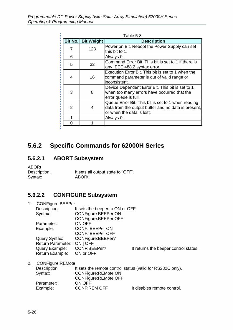
Programmable DC Power Supply (with Solar Array Simulation) 62000H Series Operating & Programming Manual
5-26
Table 5-8
Bit No. Bit Weight Description
7 128 Power on Bit. Reboot the Power Supply can set this bit to 1.
6 Always 0.
5 32 Command Error Bit. This bit is set to 1 if there is any IEEE 488.2 syntax error.
4 16 Execution Error Bit. This bit is set to 1 when the command parameter is out of valid range or inconsistent.
3 8 Device Dependent Error Bit. This bit is set to 1 when too many errors have occurred that the error queue is full.
2 4 Queue Error Bit. This bit is set to 1 when reading data from the output buffer and no data is present, or when the data is lost.
1 Always 0.
0 1
5.6.2 Specific Commands for 62000H Series
5.6.2.1 ABORT Subsystem
ABORt Description: It sets all output state to “OFF”. Syntax: ABORt
5.6.2.2 CONFIGURE Subsystem
1. CONFigure:BEEPer Description: It sets the beeper to ON or OFF. Syntax: CONFigure:BEEPer ON
CONFigure:BEEPer OFF Parameter: ON|OFF Example: CONF: BEEPer ON
CONF: BEEPer OFF Query Syntax: CONFigure:BEEPer? Return Parameter: ON | OFF Query Example: CONF:BEEPer? It returns the beeper control status. Return Example: ON or OFF
2. CONFigure:REMote
Description: It sets the remote control status (valid for RS232C only). Syntax: CONFigure:REMote ON
CONFigure:REMote OFF Parameter: ON|OFF Example: CONF:REM OFF It disables remote control.
Remote Operation
5-27
3. CONFigure:OUTPut Description: It sets the voltage/current output. Syntax: CONFigure:OUTPut ON CONFigure: OUTPut OFF Parameter: ON|OFF Example: CONFigure: OUTPut The power supply starts output.
CONFigure: OUTPut OFF The power supply stops output. Query Syntax: CONFigure: OUTPut? Query Example: CONF: OUTPut? Return Example: ON or OFF
4. CONFigure:FOLDback
Description: It sets the type of FOLDBACK PROTECT Syntax: CONFigure:FOLDback DISABLE
CONFigure:FOLDback CVTOCC CONFigure:FOLDback CCTOCV
Parameter: DISABLE|CVTOCC|CCTOCV Example: CONFigure:FOLD DISABLE
CONFigure:FOLD CVTOCC Query Syntax: CONFigure:FOLD? Query Example: CONF:FOLD? It returns the status set. Return Example: DISABLE or CVTOCC or CCTOCV
5. CONFigure:FOLDT Description: It sets the delay time of FOLDBACK PROTECT Syntax: CONFigure:FOLDT <NRf+> Parameter: 0.01~600.00 (Unit : Sec) Example: CONF:FOLDT 10 Query Syntax: CONF:FOLDT? Return Parameter: <NRf1> Query Example: CONF:FOLDT? Return Example: 1.000000e+01
6. CONFigure:APGVSet
Description: It sets the action type of APG VSET. Syntax: CONFigure:APGVSet NONE
CONFigure:APGVSet VREF5 CONFigure:APGVSet RREF Parameter: NONE | VREF5 | VREF10 | IREF | RREF Example: CONFigure:APGVSet VREF10 Query Syntax: CONFigure:APGVSet? Query Example: CONFigure:APGVSet? Return Example: VREF10
7. CONFigure:APGVMeas
Description: It sets the action type of APG VMEAS. Syntax: CONFigure:APGVMeas NONE
CONFigure: APGVMeas VREF5 CONFigure: APGVMeas IREF
Parameter: NONE | VREF5 | VREF10 | IREF Example: CONFigure:APGVMeas VREF10 Query Syntax: CONFigure: APGVMeas? Query Example: CONFigure: APGVMeas? Return Example: VREF10

Programmable DC Power Supply (with Solar Array Simulation) 62000H Series Operating & Programming Manual
5-28
8. CONFigure:APGISet
Description: It sets the action type of APG ISET. Syntax: CONFigure:APGISet NONE
CONFigure:APGISet VREF5 CONFigure:APGISet RREF
Parameter: NONE | VREF5 | VREF10 | IREF | RREF Example: CONFigure:APGISet VREF10 Query Syntax: CONFigure:APGISet? Query Example: CONFigure:APGISet? Return Example: VREF10
9. CONFigure:APGIMeas
Description: It sets the action type of APG IMEAS. Syntax: CONFigure:APGIMeas NONE
CONFigure: APGIMeas VREF5 CONFigure: APGIMeas IREF
Parameter: NONE | VREF5 | VREF10 | IREF Example: CONFigure:APGIMeas VREF10 Query Syntax: CONFigure:APGIMeas? Query Example: CONFigure:APGIMeas? Return Example: VREF10
10. CONFigure:AVG:TIMES
Description: It sets the average times of measurement for input voltage/current. Syntax: CONFigure:AVG:TIMES <NR1> Parameter: <NR1>
0: 1 time 1: 2 times 2: 4 times 3: 8 times
Example: CONFigure:AVG:TIMES 0 CONFigure:AVG:TIMES 1
Query Syntax: CONFigure:AVG:TIMES? Return Parameter: 1 |2 | 4 | 8 Query Example: CONFigure:AVG:TIMES? Return Example: 1
11. CONFigure:AVG:METHod Description: It sets the average method of AD for input voltage/current. Syntax: CONFigure:AVG:METHOD <NR1> Parameter: FIX/MOV Example: CONFigure:AVG:METHOD FIX CONFigure:AVG:METHOD MOV Query Syntax: CONFigure:AVG:METHOD? Return Parameter: FIX | MOV Query Example: CONFigure:AVG:METHOD? Return Example: FIX
12. CONFigure:BRIGhtness Description: It sets the display brightness of panel. Description: CONFigure:BRIGhtness
CONFigure: BRIGhtness DIM Parameter: HIGH | NOR | DIM

Remote Operation
5-29
Example: CONFigure: BRIGhtness HIGH CONFigure: BRIGhtness NOR CONFigure: BRIGhtness DIM Query Syntax:: CONFigure: BRIGhtness?
Return Parameter: HIGH | NOR | DIM Query Example: CONFigure: BRIGhtness ? It returns the brightness control
status of panel. Return Example: HIGH
13. CONFigure:MSTSLV:ID
Description: It sets to Master or Slave. Syntax: CONFigure:MSTSLV:ID MASTER
CONFigure:MSTSLV:ID SLAVE1 Parameter: MASTER,SLAVE1,SLAVE2,SLAVE3…….SLAVE9. Example: CONFigure:MSTSLV:ID MASTER CONFigure:MSTSLV:ID SLAVE2 Query Syntax: CONFigure:MSTSLV:ID? Return Parameter: MASTER | SLAVE1 | SLAVE2 | …… | SLAVE9 Query Example: CONF:MSTSLV:ID? Return Example: MASTER or SLAVE1~SLAVE9
Note CONFigure:MSTSLV? must be OFF when setting it. (Not in series/parallel mode.) 14. CONFigure:MSTSLV:PARSER
Description: It sets to series or parallel mode. Syntax: CONFigure:MSTSLV:PARSER PARALLEL
CONFigure:MSTSLV:PARSER SERIES Parameter: PARALLEL| SERIES Example: CONFigure:MSTSLV:PARSER PARALLEL CONFigure:MSTSLV:PARSER SERIES Query Syntax: CONFigure:MSTSLV:PARSER? Return Parameter: PARALLEL| SERIES Query Example: CONF:MSTSLV:PARSER? Return Example: PARALLEL
Note CONFigure:MSTSLV? must be OFF when setting it. (Not in series/parallel mode.) 15. CONFigure:MSTSLV:NUMSLV
Description: It sets the number of SLAVE to be controlled. Syntax: CONFigure:MSTSLV:NUMSLV <NR1> Parameter: <NR1> Example: CONFigure:MSTSLV:NUMSLV 1
CONFigure:MSTSLV:NUMSLV 2 Query Syntax: CONFigure:MSTSLV:NUMSLV? Return Parameter: <NR1> Query Example: CONF:MSTSLV:NUMSLV? Return Example: 1
Note 1. CONFigure:MSTSLV? must be OFF when setting it. (Not in series/parallel
mode.) 2. Only 1 slave can be set when in series mode and maximum 9 slaves can be
set when in parallel mode.
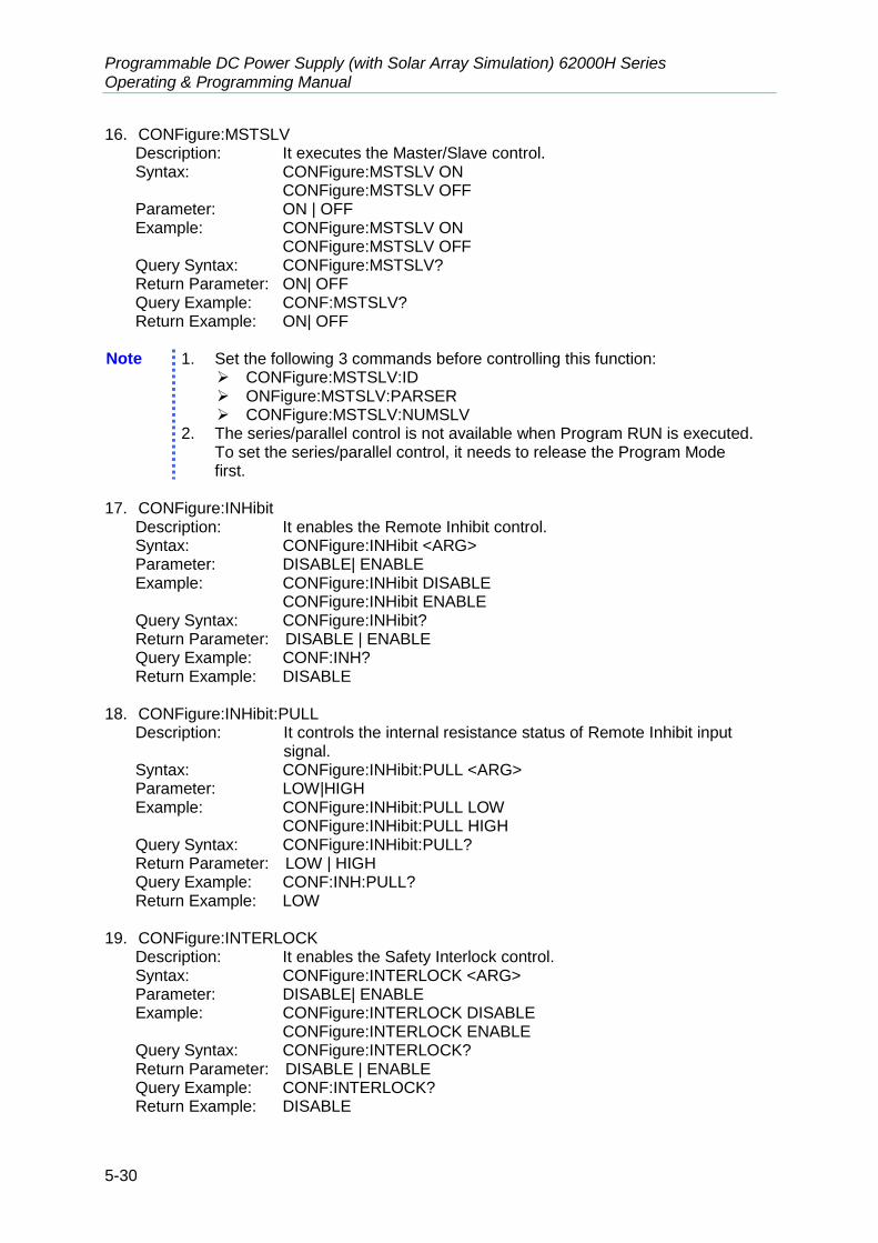
Programmable DC Power Supply (with Solar Array Simulation) 62000H Series Operating & Programming Manual
5-30
16. CONFigure:MSTSLV Description: It executes the Master/Slave control. Syntax: CONFigure:MSTSLV ON CONFigure:MSTSLV OFF Parameter: ON | OFF Example: CONFigure:MSTSLV ON CONFigure:MSTSLV OFF Query Syntax: CONFigure:MSTSLV? Return Parameter: ON| OFF Query Example: CONF:MSTSLV? Return Example: ON| OFF
Note 1. Set the following 3 commands before controlling this function:
CONFigure:MSTSLV:ID ONFigure:MSTSLV:PARSER CONFigure:MSTSLV:NUMSLV
2. The series/parallel control is not available when Program RUN is executed. To set the series/parallel control, it needs to release the Program Mode first.
17. CONFigure:INHibit
Description: It enables the Remote Inhibit control. Syntax: CONFigure:INHibit <ARG> Parameter: DISABLE| ENABLE Example: CONFigure:INHibit DISABLE CONFigure:INHibit ENABLE Query Syntax: CONFigure:INHibit? Return Parameter: DISABLE | ENABLE Query Example: CONF:INH? Return Example: DISABLE
18. CONFigure:INHibit:PULL
Description: It controls the internal resistance status of Remote Inhibit input signal.
Syntax: CONFigure:INHibit:PULL <ARG> Parameter: LOW|HIGH Example: CONFigure:INHibit:PULL LOW CONFigure:INHibit:PULL HIGH Query Syntax: CONFigure:INHibit:PULL? Return Parameter: LOW | HIGH Query Example: CONF:INH:PULL? Return Example: LOW
19. CONFigure:INTERLOCK
Description: It enables the Safety Interlock control. Syntax: CONFigure:INTERLOCK <ARG> Parameter: DISABLE| ENABLE Example: CONFigure:INTERLOCK DISABLE CONFigure:INTERLOCK ENABLE Query Syntax: CONFigure:INTERLOCK? Return Parameter: DISABLE | ENABLE Query Example: CONF:INTERLOCK? Return Example: DISABLE
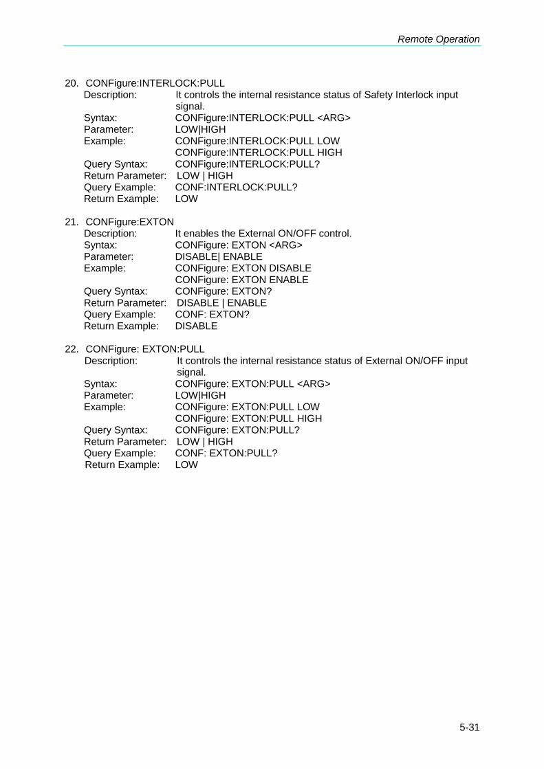
Remote Operation
5-31
20. CONFigure:INTERLOCK:PULL Description: It controls the internal resistance status of Safety Interlock input
signal. Syntax: CONFigure:INTERLOCK:PULL <ARG> Parameter: LOW|HIGH Example: CONFigure:INTERLOCK:PULL LOW CONFigure:INTERLOCK:PULL HIGH Query Syntax: CONFigure:INTERLOCK:PULL? Return Parameter: LOW | HIGH Query Example: CONF:INTERLOCK:PULL? Return Example: LOW
21. CONFigure:EXTON
Description: It enables the External ON/OFF control. Syntax: CONFigure: EXTON <ARG> Parameter: DISABLE| ENABLE Example: CONFigure: EXTON DISABLE CONFigure: EXTON ENABLE Query Syntax: CONFigure: EXTON? Return Parameter: DISABLE | ENABLE Query Example: CONF: EXTON? Return Example: DISABLE
22. CONFigure: EXTON:PULL
Description: It controls the internal resistance status of External ON/OFF input signal.
Syntax: CONFigure: EXTON:PULL <ARG> Parameter: LOW|HIGH Example: CONFigure: EXTON:PULL LOW CONFigure: EXTON:PULL HIGH Query Syntax: CONFigure: EXTON:PULL? Return Parameter: LOW | HIGH Query Example: CONF: EXTON:PULL? Return Example: LOW
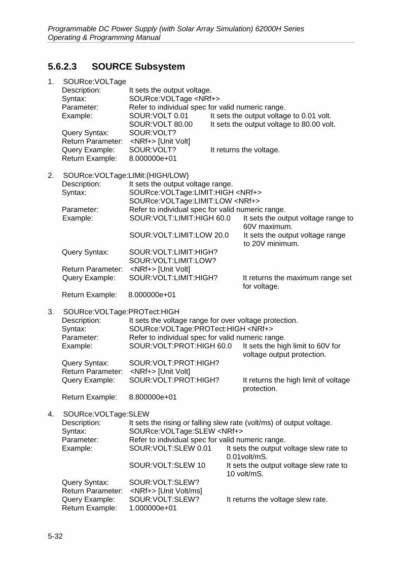
Programmable DC Power Supply (with Solar Array Simulation) 62000H Series Operating & Programming Manual
5-32
5.6.2.3 SOURCE Subsystem
1. SOURce:VOLTage Description: It sets the output voltage. Syntax: SOURce:VOLTage <NRf+> Parameter: Refer to individual spec for valid numeric range. Example: SOUR:VOLT 0.01 It sets the output voltage to 0.01 volt.
SOUR:VOLT 80.00 It sets the output voltage to 80.00 volt. Query Syntax: SOUR:VOLT? Return Parameter: <NRf+> [Unit Volt] Query Example: SOUR:VOLT? It returns the voltage. Return Example: 8.000000e+01
2. SOURce:VOLTage:LIMit:{HIGH/LOW}
Description: It sets the output voltage range. Syntax: SOURce:VOLTage:LIMIT:HIGH <NRf+>
SOURce:VOLTage:LIMIT:LOW <NRf+> Parameter: Refer to individual spec for valid numeric range. Example: SOUR:VOLT:LIMIT:HIGH 60.0 It sets the output voltage range to
60V maximum. SOUR:VOLT:LIMIT:LOW 20.0 It sets the output voltage range
to 20V minimum. Query Syntax: SOUR:VOLT:LIMIT:HIGH?
SOUR:VOLT:LIMIT:LOW? Return Parameter: <NRf+> [Unit Volt] Query Example: SOUR:VOLT:LIMIT:HIGH? It returns the maximum range set
for voltage. Return Example: 8.000000e+01
3. SOURce:VOLTage:PROTect:HIGH
Description: It sets the voltage range for over voltage protection. Syntax: SOURce:VOLTage:PROTect:HIGH <NRf+> Parameter: Refer to individual spec for valid numeric range. Example: SOUR:VOLT:PROT:HIGH 60.0 It sets the high limit to 60V for
voltage output protection. Query Syntax: SOUR:VOLT:PROT:HIGH? Return Parameter: <NRf+> [Unit Volt] Query Example: SOUR:VOLT:PROT:HIGH? It returns the high limit of voltage
protection. Return Example: 8.800000e+01
4. SOURce:VOLTage:SLEW
Description: It sets the rising or falling slew rate (volt/ms) of output voltage. Syntax: SOURce:VOLTage:SLEW <NRf+> Parameter: Refer to individual spec for valid numeric range. Example: SOUR:VOLT:SLEW 0.01 It sets the output voltage slew rate to
0.01volt/mS. SOUR:VOLT:SLEW 10 It sets the output voltage slew rate to
10 volt/mS. Query Syntax: SOUR:VOLT:SLEW? Return Parameter: <NRf+> [Unit Volt/ms] Query Example: SOUR:VOLT:SLEW? It returns the voltage slew rate. Return Example: 1.000000e+01

Remote Operation
5-33
5. SOURce: CURRent
Description: It sets the output current (ampere). Syntax: SOURce:CURRent <NRf+> Parameter: Refer to individual spec for valid numeric range. Example: SOUR:CURR 1 It sets the output current to 1 amps.
SOUR:CURR 60.00 It sets the output current to 60.00 amps. Query Syntax: SOUR:CURR? Return Parameter: <NRf+> [Unit Amp] Query Example: SOUR:CURR? It returns the current. Return Example: 1.000000e+00
6. SOURce:CURRent:LIMit:{HIGH/LOW}
Description: It sets the output current range. Syntax: SOURce:CURRent:LIMIT:HIGH <NRf+>
SOURce:CURRent:LIMIT:LOW <NRf+> Parameter: Refer to individual spec for valid numeric range. Example: SOUR:CURR:LIMIT:HIGH 60.0 It sets the output current range
to 60A maximum. SOUR:CURR:LIMIT:LOW 20.0 It set the low limit to 20A for
current output protection. Query Syntax: SOUR:CURR:LIMIT:HIGH?
SOUR:CURR:LIMIT:LOW? Return Parameter: <NRf+> [Unit Amp] Query Example: SOUR:CURR:LIMIT:HIGH? It returns the maximum range set
for current. Return Example: 6.000000e+01
7. SOURce:CURRent:PROTect:HIGH
Description: It sets the current range for over current protection. Syntax: SOURce:CURRent:PROTect:HIGH <NRf+> Parameter: Refer to individual spec for valid numeric range. Example: SOUR:CURR:PROT:HIGH 60.0 It sets the high limit to 60A
for current output protection. Query Syntax: SOUR:CURR:PROT:HIGH? Return Parameter: <NRf+> [Unit Amp] Query Example: SOUR:CURR:PROT:HIGH? It returns the high limit of
current protection. Return Example: 6.000000e+01
8. SOURce:CURRent:SLEW
Description: It sets the rising or falling slew rate (amp/ms) of output current. Syntax: SOURce:CURRent:SLEW <NRf+> Parameter: Refer to individual spec for valid numeric range. Example: SOUR:CURR:SLEW 0.01 It sets the output current slew rate to
0.01 Amp/mS. SOUR:CURR:SLEW 1.00 It sets the output current slew rate to
1.00 Amp/mS. Query Syntax: SOUR:CURR:SLEW? Return Parameter: <NR f+> [Unit Amp/ms] Query Example: SOUR:CURR:SLEW? It returns the current slew rate. Return Example: 1.000000e+00

Programmable DC Power Supply (with Solar Array Simulation) 62000H Series Operating & Programming Manual
5-34
9. SOURce:CURRent:SLEWINF Description: It sets the I Slewrate to INF. Syntax: SOURce:CURRent:SLEWINF ENABLE
SOURce:CURRent:SLEWINF DISABLE Parameter: ENABLE/DISABLE Example: SOUR:CURR:SLEWINF ENABLE It sets the I Slewrate to INF.
SOUR:CURR:SLEWINF DISABLE It resets the I Slewrate and returns to 1A/ms.
Query Syntax: SOUR:CURR:SLEW? Return Parameter: INF. Or <NRf+>[Unit = Ampere] Query Example: SOUR:CURR:SLEW? It returns the setting. Return Example: INF.
10. SOURce:POWer:PROTect:HIGH
Description: It sets the over power point (Watt) of output power. Syntax: SOURce:POWer:PROTect:HIGH <NRf+> Parameter: Refer to individual spec for valid numeric range. Example: SOURce:POWer:PROTect:HIGH 1260 It sets the over power
point 1260. Query Syntax: SOURce:POWer:PROTect:HIGH? Return Parameter: <NR f+> [Watt] Query Example: SOURce:POWer:PROTect:HIGH? It returns the over
power setting value. Return Example: 1.260000e+03
11. SOURce:DCON:{RISE/FALL}
Description: It sets the DC_ON signal active point. Syntax: SOURce:DCON:RISE <NRf+>
SOURce:DCON:FALL <NRf+> Parameter: Refer to individual spec for valid numeric range. Example: SOUR:DCON:RISE 79.5 It sets the DC_ON rise to 79.5V.
SOUR:DCON:FALL 0.5 It sets the DC_ON fall to 0.5V. Query Syntax: SOUR:DCON:RISE? SOUR:DCON:FALL? Return Parameter: <NRf+> [Unit = Volt] Query Example: SOUR:DCON:RISE? It returns the setting. Return Example: 7.950000e+01
Note The output must be OFF for setting.

Remote Operation
5-35
5.6.2.4 FETCH Subsystem
1. FETCh:VOLTage? Description: It measures the output of Power Supply and returns real time
voltage. Query Syntax: FETCh:VOLTage? Return Parameter: <NRf+> [Unit Volt] Query Example: FETC:VOLT? Return Example: 9.983100e+00
2. FETCh:CURRent?
Description: It measures the output of Power Supply and returns real time current.
Query Syntax: FETCh:CURRent? Return Parameter: <NRf+> [Unit Amp] Query Example: FETC:CURR? Return Example: 2.000000e-04
3. FETCh:POWer?
Description: It measures the output of Power Supply and returns real time power. Query Syntax: FETCh:POWer? Return Parameter: <NRf+> [Unit Amp] Query Example: FETC:POW? Return Example: 5.000000e+03
4. FETCh:STATus?
Description: It returns the status code of Power Supply’s state. Query Syntax: FETCh:STATus? Return Parameter: <Arg1><,><Arg2><,><Arg3>
<Arg1>: return warning message 0~65535, 0: no warning, use binary for the rest and identify the cause of error. BIT 0: OVP BIT 1: OCP BIT 2: OPP BIT 3: Remote Inhibit BIT 4: OTP BIT 5: FAN_LOCK BIT 6: SENSE FAULT BIT 7: SERIES FAULT BIT 8: Reserved BIT 9: AC FAULT BIT 10: FOLD Back CV to CC BIT 11: FOLD Back CC to CV BIT 12: Reserved BIT 13: Reserved BIT 14: Reserved BIT 15: Reserved <Arg2>: ON|OFF output status at present <Arg3>: CV or CC status at present
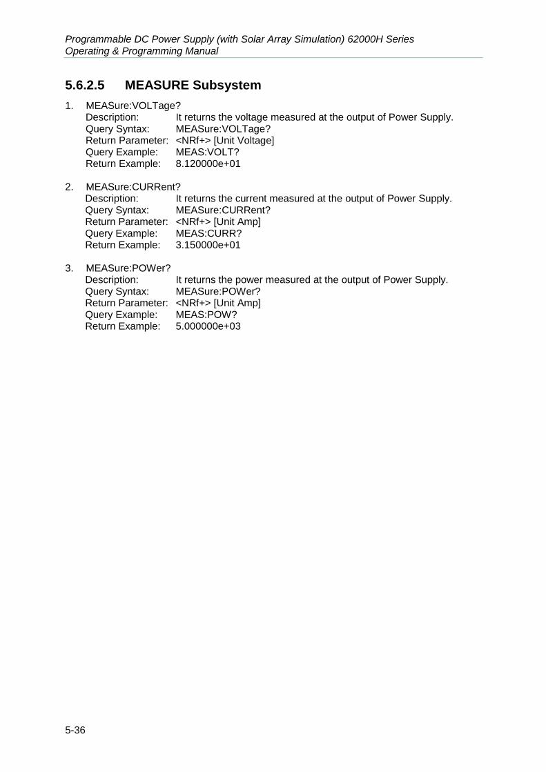
Programmable DC Power Supply (with Solar Array Simulation) 62000H Series Operating & Programming Manual
5-36
5.6.2.5 MEASURE Subsystem
1. MEASure:VOLTage? Description: It returns the voltage measured at the output of Power Supply. Query Syntax: MEASure:VOLTage? Return Parameter: <NRf+> [Unit Voltage] Query Example: MEAS:VOLT? Return Example: 8.120000e+01
2. MEASure:CURRent?
Description: It returns the current measured at the output of Power Supply. Query Syntax: MEASure:CURRent? Return Parameter: <NRf+> [Unit Amp] Query Example: MEAS:CURR? Return Example: 3.150000e+01
3. MEASure:POWer?
Description: It returns the power measured at the output of Power Supply. Query Syntax: MEASure:POWer? Return Parameter: <NRf+> [Unit Amp] Query Example: MEAS:POW? Return Example: 5.000000e+03
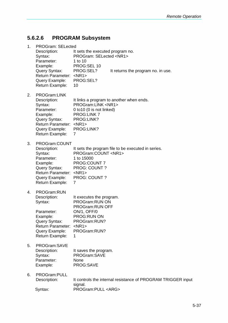
Remote Operation
5-37
5.6.2.6 PROGRAM Subsystem
1. PROGram: SELected Description: It sets the executed program no. Syntax: PROGram: SELected <NR1> Parameter: 1 to 10 Example: PROG:SEL 10 Query Syntax: PROG:SEL? It returns the program no. in use. Return Parameter: <NR1> Query Example: PROG:SEL? Return Example: 10
2. PROGram:LINK
Description: It links a program to another when ends. Syntax: PROGram:LINK <NR1> Parameter: 0 to10 (0 is not linked) Example: PROG:LINK 7 Query Syntax: PROG:LINK? Return Parameter: <NR1> Query Example: PROG:LINK? Return Example: 7
3. PROGram:COUNT
Description: It sets the program file to be executed in series. Syntax: PROGram:COUNT <NR1> Parameter: 1 to 15000 Example: PROG:COUNT 7 Query Syntax: PROG: COUNT ? Return Parameter: <NR1> Query Example: PROG: COUNT ? Return Example: 7
4. PROGram:RUN
Description: It executes the program. Syntax: PROGram:RUN ON
PROGram:RUN OFF Parameter: ON/1, OFF/0 Example: PROG:RUN ON Query Syntax: PROGram:RUN? Return Parameter: <NR1> Query Example: PROGram:RUN? Return Example: 1
5. PROGram:SAVE
Description: It saves the program. Syntax: PROGram:SAVE Parameter: None Example: PROG:SAVE
6. PROGram:PULL
Description: It controls the internal resistance of PROGRAM TRIGGER input signal.
Syntax: PROGram:PULL <ARG>
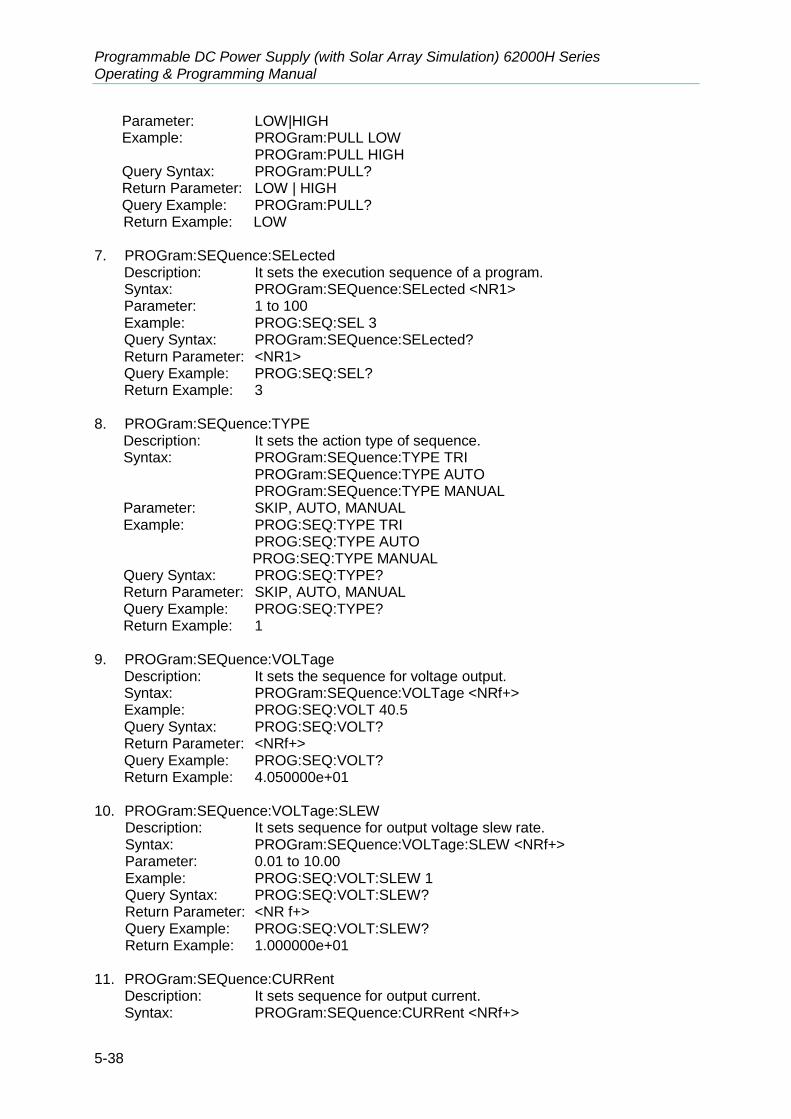
Programmable DC Power Supply (with Solar Array Simulation) 62000H Series Operating & Programming Manual
5-38
Parameter: LOW|HIGH Example: PROGram:PULL LOW PROGram:PULL HIGH Query Syntax: PROGram:PULL? Return Parameter: LOW | HIGH Query Example: PROGram:PULL? Return Example: LOW
7. PROGram:SEQuence:SELected
Description: It sets the execution sequence of a program. Syntax: PROGram:SEQuence:SELected <NR1> Parameter: 1 to 100 Example: PROG:SEQ:SEL 3 Query Syntax: PROGram:SEQuence:SELected? Return Parameter: <NR1> Query Example: PROG:SEQ:SEL? Return Example: 3
8. PROGram:SEQuence:TYPE
Description: It sets the action type of sequence. Syntax: PROGram:SEQuence:TYPE TRI
PROGram:SEQuence:TYPE AUTO PROGram:SEQuence:TYPE MANUAL Parameter: SKIP, AUTO, MANUAL Example: PROG:SEQ:TYPE TRI
PROG:SEQ:TYPE AUTO PROG:SEQ:TYPE MANUAL
Query Syntax: PROG:SEQ:TYPE? Return Parameter: SKIP, AUTO, MANUAL Query Example: PROG:SEQ:TYPE? Return Example: 1
9. PROGram:SEQuence:VOLTage
Description: It sets the sequence for voltage output. Syntax: PROGram:SEQuence:VOLTage <NRf+> Example: PROG:SEQ:VOLT 40.5 Query Syntax: PROG:SEQ:VOLT? Return Parameter: <NRf+> Query Example: PROG:SEQ:VOLT? Return Example: 4.050000e+01
10. PROGram:SEQuence:VOLTage:SLEW
Description: It sets sequence for output voltage slew rate. Syntax: PROGram:SEQuence:VOLTage:SLEW <NRf+> Parameter: 0.01 to 10.00 Example: PROG:SEQ:VOLT:SLEW 1 Query Syntax: PROG:SEQ:VOLT:SLEW? Return Parameter: <NR f+> Query Example: PROG:SEQ:VOLT:SLEW? Return Example: 1.000000e+01
11. PROGram:SEQuence:CURRent
Description: It sets sequence for output current. Syntax: PROGram:SEQuence:CURRent <NRf+>

Remote Operation
5-39
Example: PROG:SEQ:CURR 40.5 Query Syntax: PROG:SEQ:CURR? Return Parameter: <NRf+> Query Example: PROG:SEQ:CURR? Return Example: 4.500000e+01
12. PROGram:SEQuence:CURRent:SLEW
Description: It sets sequence for output voltage slew rate. Syntax: PROGram:SEQuence:CURRent:SLEW <NRf+> Example: PROG:SEQ:CURR:SLEW 10 Query Syntax: PROG:SEQ:CURR:SLEW? Return Parameter: <NR1> Query Example: PROG:SEQ:CURR:SLEW? Return Example: 1.000000e+00
13. PROGram:SEQuence:CURRent:SLEWINF
Description: It sets the slewrate of sequence current output to INF. Syntax: PROGram:SEQuence:CURRent:SLEWINF ENABLE
PROGram:SEQuence:CURRent:SLEWINF DISABLE Parameter: ENABLE/DISABLE Example: PROGram:SEQuence:CURRent:SLEWINF ENABLE sets the
Slewrate to INF PROGram:SEQuence:CURRent:SLEWINF DISABLE releases the Slewrate INF and return to 1A/ms
Query Syntax: PROGram:SEQuence:CURRent:SLEW? Return Parameter: INF. Or <NRf+>[Unit Amp] Query Example: PROGram:SEQuence:CURRent:SLEW? It returns the settings. Return Example: INF.
14. PROGram:SEQuence:TIME
Description: It sets the sequence for the duration of time. Syntax: PROGram:SEQuence:TIME <NRf+> Parameter: 0.005~15000, 0 (0 means end) Example: PROG:SEQ:TIME 10 Query Syntax: PROG:SEQ:TIME? Return Parameter: <NR f+> Query Example: PROG:SEQ:TIME? Return Example: 1.000000e+01
15. PROGram:CLEAR
Description: It clears the sequence. Syntax: PROGram:CLEAR Example: PROG:CLEAR
16. PROGram:ADD
Description: It adds a sequence. Syntax: PROGram:ADD <NR1> Parameter: 1~100 (based on the remaining SEQUENCE no. for configuration) Example: PROG:ADD Query Syntax: PROGram:ADD? Return Parameter: <NR1> Query Example: PROGram:ADD? Return Example: 85 – it indicates the remaining no. is 85.
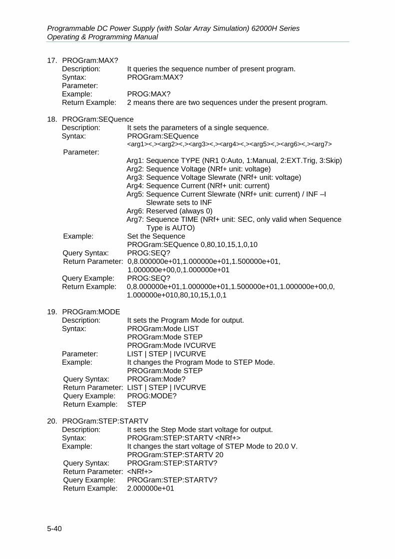
Programmable DC Power Supply (with Solar Array Simulation) 62000H Series Operating & Programming Manual
5-40
17. PROGram:MAX? Description: It queries the sequence number of present program. Syntax: PROGram:MAX? Parameter: Example: PROG:MAX? Return Example: 2 means there are two sequences under the present program.
18. PROGram:SEQuence
Description: It sets the parameters of a single sequence. Syntax: PROGram:SEQuence
<arg1><,><arg2><,><arg3><,><arg4><,><arg5><,><arg6><,><arg7>
Parameter: Arg1: Sequence TYPE (NR1 0:Auto, 1:Manual, 2:EXT.Trig, 3:Skip) Arg2: Sequence Voltage (NRf+ unit: voltage) Arg3: Sequence Voltage Slewrate (NRf+ unit: voltage) Arg4: Sequence Current (NRf+ unit: current) Arg5: Sequence Current Slewrate (NRf+ unit: current) / INF –I
Slewrate sets to INF Arg6: Reserved (always 0) Arg7: Sequence TIME (NRf+ unit: SEC, only valid when Sequence
Type is AUTO) Example: Set the Sequence
PROGram:SEQuence 0,80,10,15,1,0,10 Query Syntax: PROG:SEQ? Return Parameter: 0,8.000000e+01,1.000000e+01,1.500000e+01,
1.000000e+00,0,1.000000e+01 Query Example: PROG:SEQ? Return Example: 0,8.000000e+01,1.000000e+01,1.500000e+01,1.000000e+00,0,
1.000000e+010,80,10,15,1,0,1 19. PROGram:MODE
Description: It sets the Program Mode for output. Syntax: PROGram:Mode LIST PROGram:Mode STEP PROGram:Mode IVCURVE Parameter: LIST | STEP | IVCURVE Example: It changes the Program Mode to STEP Mode. PROGram:Mode STEP
Query Syntax: PROGram:Mode? Return Parameter: LIST | STEP | IVCURVE Query Example: PROG:MODE? Return Example: STEP 20. PROGram:STEP:STARTV
Description: It sets the Step Mode start voltage for output. Syntax: PROGram:STEP:STARTV <NRf+> Example: It changes the start voltage of STEP Mode to 20.0 V. PROGram:STEP:STARTV 20
Query Syntax: PROGram:STEP:STARTV? Return Parameter: <NRf+> Query Example: PROGram:STEP:STARTV? Return Example: 2.000000e+01
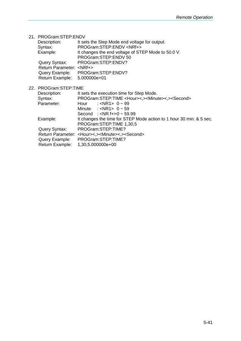
Remote Operation
5-41
21. PROGram:STEP:ENDV Description: It sets the Step Mode end voltage for output. Syntax: PROGram:STEP:ENDV <NRf+> Example: It changes the end voltage of STEP Mode to 50.0 V. PROGram:STEP:ENDV 50
Query Syntax: PROGram:STEP:ENDV? Return Parameter: <NRf+> Query Example: PROGram:STEP:ENDV? Return Example: 5.000000e+01 22. PROGram:STEP:TIME
Description: It sets the execution time for Step Mode. Syntax: PROGram:STEP:TIME <Hour><,><Minute><,><Second> Parameter: Hour : <NR1> 0 ~ 99 Minute : <NR1> 0 ~ 59 Second : <NR f+> 0 ~ 59.99 Example: It changes the time for STEP Mode action to 1 hour 30 min. & 5 sec. PROGram:STEP:TIME 1,30,5
Query Syntax: PROGram:STEP:TIME? Return Parameter: <Hour><,><Minute><,><Second> Query Example: PROGram:STEP:TIME? Return Example: 1,30,5.000000e+00
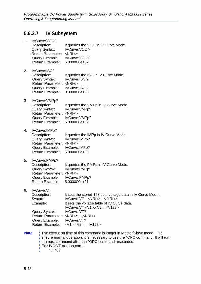
Programmable DC Power Supply (with Solar Array Simulation) 62000H Series Operating & Programming Manual
5-42
5.6.2.7 IV Subsystem
1. IVCurve:VOC? Description: It queries the VOC in IV Curve Mode. Query Syntax: IVCurve:VOC ? Return Parameter: <NRf+> Query Example: IVCurve:VOC ?
Return Example: 6.000000e+02 2. IVCurve:ISC?
Description: It queries the ISC in IV Curve Mode. Query Syntax: IVCurve:ISC ? Return Parameter: <NRf+> Query Example: IVCurve:ISC ? Return Example: 8.000000e+00 3. IVCurve:VMPp?
Description: It queries the VMPp in IV Curve Mode. Query Syntax: IVCurve:VMPp?
Return Parameter: <NRf+> Query Example: IVCurve:VMPp? Return Example: 5.000000e+02 4. IVCurve:IMPp?
Description: It queries the IMPp in IV Curve Mode. Query Syntax: IVCurve:IMPp? Return Parameter: <NRf+> Query Example: IVCurve:IMPp? Return Example: 5.000000e+00
5. IVCurve:PMPp?
Description: It queries the PMPp in IV Curve Mode. Query Syntax: IVCurve:PMPp? Return Parameter: <NRf+> Query Example: IVCurve:PMPp?
Return Example: 5.000000e+01 6. IVCurve:VT
Description: It sets the stored 128 dots voltage data in IV Curve Mode. Syntax: IVCurve:VT <NRf+>...< NRf+> Example: It sets the voltage table of IV Curve data. IVCurve:VT <V1>,<V2,...<V128>
Query Syntax: IVCurve:VT? Return Parameter: <NRf+>,...,<NRf+> Query Example: IVCurve:VT? Return Example: <V1>,<V2>,...<V128> Note The execution time of this command is longer in Master/Slave mode. To
ensure normal operation, it is necessary to use the *OPC command. It will run the next command after the *OPC command responded. Ex.: IVC:VT xxx,xxx,xxx,... *OPC?

Remote Operation
5-43
7. IVCurve:IT Description: It sets the stored 128 dots current data in IV Curve Mode. Syntax: IVCurve:IT <NRf+>...< NRf+> Example: It sets the current table of IV Curve data. IVCurve:IT <I1>,<I2>,...<I128>
Query Syntax: IVCurve:IT? Return Parameter: <NRf+>,...,<NRf+> Query Example: IVCurve:IT? Return Example: <I1>,<I1>,...<I128> Note The execution time of this command is longer in Master/Slave mode. To
ensure normal operation, it is necessary to use the *OPC command. It will run the next command after the *OPC command responded. Ex.: IVC:VT xxx,xxx,xxx,... *OPC?
8. IVCurve:EDIT <NR1>
Description: It selects the stored table to be set in IV Curve Mode. There are 100 storted tables (1~100) and the default is 1.
Syntax: IVCurve:EDIT <NR1> Example: It sets the IV Curve stored table to 1. IVCurve:EDIT 1
Query Syntax: IVCurve:EDIT? Return Parameter: <NR1> Query Example: IVCurve:EDIT? Return Example: 1 9. IVCurve:SELect <NR1>
Description: It selects the stored table to be run in IV Curve Mode. There are 100 storted tables (1~100) and the default is 1.
Syntax: IVCurve:SELect <NR1> Example: It selets the IV Curve stored table to 1. IVCurve:SELect 1
Query Syntax: IVCurve:SELect? Return Parameter: <NR1> Query Example: IVCurve:SELect? Return Example: 1 10. IVCurve:SEQuence:SELected
Description: It selects the running sequence of IV_PROGRAM. Syntax: IVCurve:SEQuence:SELected <NR1> Parameter: 1 to 100 Example: IVC:SEQ:SEL 3 Query Syntax: IVC:SEQuence:SELected? Return Parameter: <NR1> Query Example: IVC:SEQ:SEL? Return Example: 3
Note Ensure the IV-Program has the sequence desired before selecting it. If not, use
PROG:ADD command to add a new Sequence.
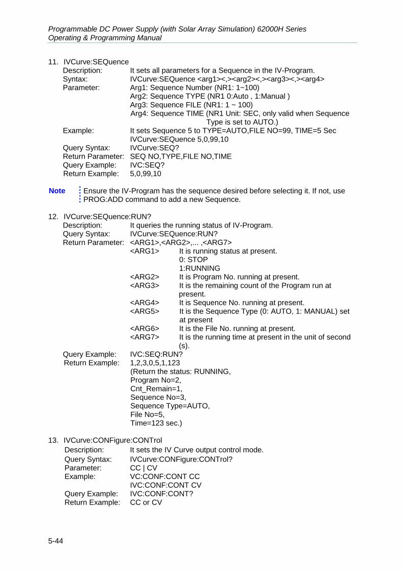
Programmable DC Power Supply (with Solar Array Simulation) 62000H Series Operating & Programming Manual
5-44
11. IVCurve:SEQuence Description: It sets all parameters for a Sequence in the IV-Program. Syntax: IVCurve:SEQuence <arg1><,><arg2><,><arg3><,><arg4> Parameter: Arg1: Sequence Number (NR1: 1~100)
Arg2: Sequence TYPE (NR1 0:Auto , 1:Manual ) Arg3: Sequence FILE (NR1: 1 ~ 100)
Arg4: Sequence TIME (NR1 Unit: SEC, only valid when Sequence Type is set to AUTO.)
Example: It sets Sequence 5 to TYPE=AUTO,FILE NO=99, TIME=5 Sec IVCurve:SEQuence 5,0,99,10
Query Syntax: IVCurve:SEQ? Return Parameter: SEQ NO,TYPE,FILE NO,TIME Query Example: IVC:SEQ? Return Example: 5,0,99,10
Note Ensure the IV-Program has the sequence desired before selecting it. If not, use PROG:ADD command to add a new Sequence.
12. IVCurve:SEQuence:RUN?
Description: It queries the running status of IV-Program. Query Syntax: IVCurve:SEQuence:RUN? Return Parameter: <ARG1>,<ARG2>,... ,<ARG7>
<ARG1> It is running status at present. 0: STOP 1:RUNNING <ARG2> It is Program No. running at present. <ARG3> It is the remaining count of the Program run at
present. <ARG4> It is Sequence No. running at present. <ARG5> It is the Sequence Type (0: AUTO, 1: MANUAL) set
at present <ARG6> It is the File No. running at present. <ARG7> It is the running time at present in the unit of second
(s). Query Example: IVC:SEQ:RUN? Return Example: 1,2,3,0,5,1,123
(Return the status: RUNNING, Program No=2, Cnt_Remain=1, Sequence No=3, Sequence Type=AUTO, File No=5, Time=123 sec.) 13. IVCurve:CONFigure:CONTrol
Description: It sets the IV Curve output control mode.
Query Syntax: IVCurve:CONFigure:CONTrol? Parameter: CC | CV Example: VC:CONF:CONT CC
IVC:CONF:CONT CV Query Example: IVC:CONF:CONT? Return Example: CC or CV
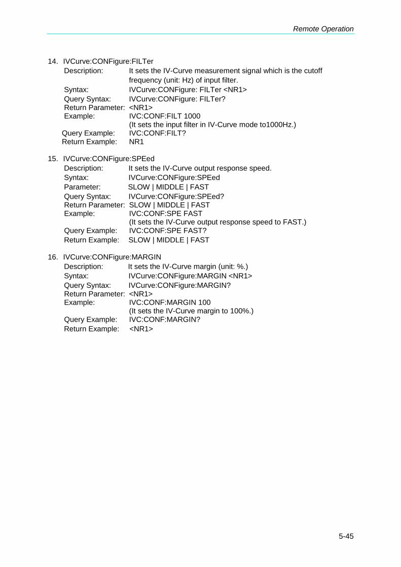
Remote Operation
5-45
14. IVCurve:CONFigure:FILTer
Description: It sets the IV-Curve measurement signal which is the cutoff
frequency (unit: Hz) of input filter.
Syntax: IVCurve:CONFigure: FILTer <NR1>
Query Syntax: IVCurve:CONFigure: FILTer? Return Parameter: <NR1>
Example: IVC:CONF:FILT 1000 (It sets the input filter in IV-Curve mode to1000Hz.)
Query Example: IVC:CONF:FILT? Return Example: NR1
15. IVCurve:CONFigure:SPEed
Description: It sets the IV-Curve output response speed.
Syntax: IVCurve:CONFigure:SPEed
Parameter: SLOW | MIDDLE | FAST
Query Syntax: IVCurve:CONFigure:SPEed? Return Parameter: SLOW | MIDDLE | FAST
Example: IVC:CONF:SPE FAST (It sets the IV-Curve output response speed to FAST.)
Query Example: IVC:CONF:SPE FAST?
Return Example: SLOW | MIDDLE | FAST 16. IVCurve:CONFigure:MARGIN
Description: It sets the IV-Curve margin (unit: %.)
Syntax: IVCurve:CONFigure:MARGIN <NR1>
Query Syntax: IVCurve:CONFigure:MARGIN? Return Parameter: <NR1>
Example: IVC:CONF:MARGIN 100 (It sets the IV-Curve margin to 100%.)
Query Example: IVC:CONF:MARGIN?
Return Example: <NR1>

Programmable DC Power Supply (with Solar Array Simulation) 62000H Series Operating & Programming Manual
5-46
5.6.2.8 SAS Subsystem
1. SAS:VOC Description: It sets the VOC in SAS Mode. Syntax: SAS:VOC <NRf+> Example: It changes the VOC of SAS to 600.0 V.
SAS:VOC 600 Query Syntax: SAS:VOC ? Return Parameter: <NRf+> Query Example: SAS:VOC ? Return Example: 6.000000e+02
2. SAS:ISC
Description: It sets the ISC in SAS Mode. Syntax: SAS:ISC <NRf+> Example: It changes the ISC of SAS to 8.0 A.
SAS:ISC 8 Query Syntax: SAS:ISC ? Return Parameter: <NRf+> Query Example: SAS:ISC ? Return Example: 8.000000e+00
3. SAS:VMPp
Description: It sets the VMPp in SAS Mode. Syntax: SAS:VMPp <NRf+> Example: It changes the VMPp of SAS to 500.0 V.
SAS:VMPp 500 Query Syntax: SAS:VMPp ? Return Parameter: <NRf+> Query Example: SAS:VMPp ? Return Example: 5.000000e+02
4. SAS:IMPp
Description: It sets the IMPp in SAS Mode. Syntax: SAS:IMPp <NRf+> Example: It changes the IMPp of SAS to 5.0 A.
SAS:IMPp 5 Query Syntax: SAS:IMPp ? Return Parameter: <NRf+> Query Example: SAS:IMPp ? Return Example: 5.000000e+00
Note Due to the formula limitation, following conditions must be followed when
running in SAS mode.
ISC
IMP-1 VOC VMP
ISC IMP , VOC VMP
0 IMP ,0 VMP ,0 ISC ,0 VOC
5. TRIG
Description: It updates the output waveform when SAS Mode is running. Syntax: TRIG

Remote Operation
5-47
Example: SAS:VOC 600 SAS:ISC 8 SAS:IMPp 5
SAS:VMPp 400 TRIG
6. SAS:PMPp Description: It sets the PMPp in EN50530 Mode.
Syntax: SAS:VMPp <NRf+> Example: It changes the PMPp of SAS to 1500.0 W.
SAS:PMPp 1500 Query Syntax: SAS:PMPp ? Return Parameter: <NRf+> Query Example: SAS:PMPp ? Return Example: 1.500000e+03
7. SAS:VMPp
Description: It sets the VMPp in EN50530 Mode. Syntax: SAS:VMPp <NRf+> Example: It changes the VMPp of SAS to 500.0 V.
SAS:VMPp 500 Query Syntax: SAS:VMPp ? Return Parameter: <NRf+> Query Example: SAS:VMPp ? Return Example: 5.000000e+02
8. SAS:TECH
Description: It sets the TECH in EN50530 Mode. Syntax: SAS:TECH <NR1> Parameter: CSI/TF Example: SAS:TECH CSI
SAS:TECH TF Query Syntax: SAS:TECH? Return Parameter: CSI | TF Query Example: SAS:TECH? Return Example: CSI
9. SAS:IRR
Description: It sets the irritation in EN50530 Mode. Syntax: SAS:IRR <NR1> Parameter: <NR1> Example: SAS:IRR 1000
SAS:IRR 3000 Query Syntax: SAS:IRR? Return Parameter: <NR1> Query Example: SAS:IRR? Return Example: 1000
10. SAS:SANDIA:IRRREF
Description: It sets the irritation reference in SANDIA Mode. Syntax: SAS:SANDIA:IRRREF <NR1> Parameter: <NR1> Example: SAS:SANDIA:IRRREF 1000
SAS:SANDIA:IRRREF 3000

Programmable DC Power Supply (with Solar Array Simulation) 62000H Series Operating & Programming Manual
5-48
Query Syntax: SAS:SANDIA:IRRREF? Return Parameter: <NR1> Query Example: SAS:SANDIA:IRRREF Return Example: 1000
11. SAS:SANDIA:TMPREF
Description: It sets the temperature reference in SANDIA Mode. Syntax: SAS:SANDIA:TMPREF <NRf+> Parameter: <NRf+> Example: SAS:SANDIA:TMPREF 100
SAS:SANDIA:TMPREF -100 Query Syntax: SAS:SANDIA:TMPREF? Return Parameter: <NRf+> Query Example: SAS:SANDIA:TMPREF? Return Example: -1.000000e+02
12. SAS:SANDIA:BETA
Description: It sets the BETA parameter in SANDIA Mode. Syntax: SAS:SANDIA:BETA <NRf+> Parameter: <NRf+> Example: SAS:SANDIA:BETA 0
SAS:SANDIA:BETA -2 Query Syntax: SAS:SANDIA:BETA? Return Parameter: <NRf+> Query Example: SAS:SANDIA:BETA? Return Example: -2.000000e+00
13. SAS:SANDIA:FF
Description: It sets the fill factor in SANDIA Mode. Syntax: SAS:SANDIA:FF <NRf+> Parameter: <NRf+> Example: SAS:SANDIA:FF 0.4
SAS:SANDIA:FF 0.95 Query Syntax: SAS:SANDIA:FF? Return Parameter: <NRf+> Query Example: SAS:SANDIA:FF? Return Example: -2.000000e+00
14. SAS:SANDIA:IRR
Description: It sets the irritation in SANDIA Mode. Syntax: SAS:SANDIA:IRR <NR1> Parameter: <NR1> Example: SAS:SANDIA:IRR 1000
SAS:SANDIA:IRR 3000 Query Syntax: SAS:SANDIA:IRR? Return Parameter: <NR1> Query Example: SAS:SANDIA:IRR Return Example: 1000
15. SAS:SANDIA:TMP
Description: It sets the temperature in SANDIA Mode. Syntax: SAS:SANDIA:TMP <NRf+> Parameter: <NRf+> Example: SAS:SANDIA:TMP 100
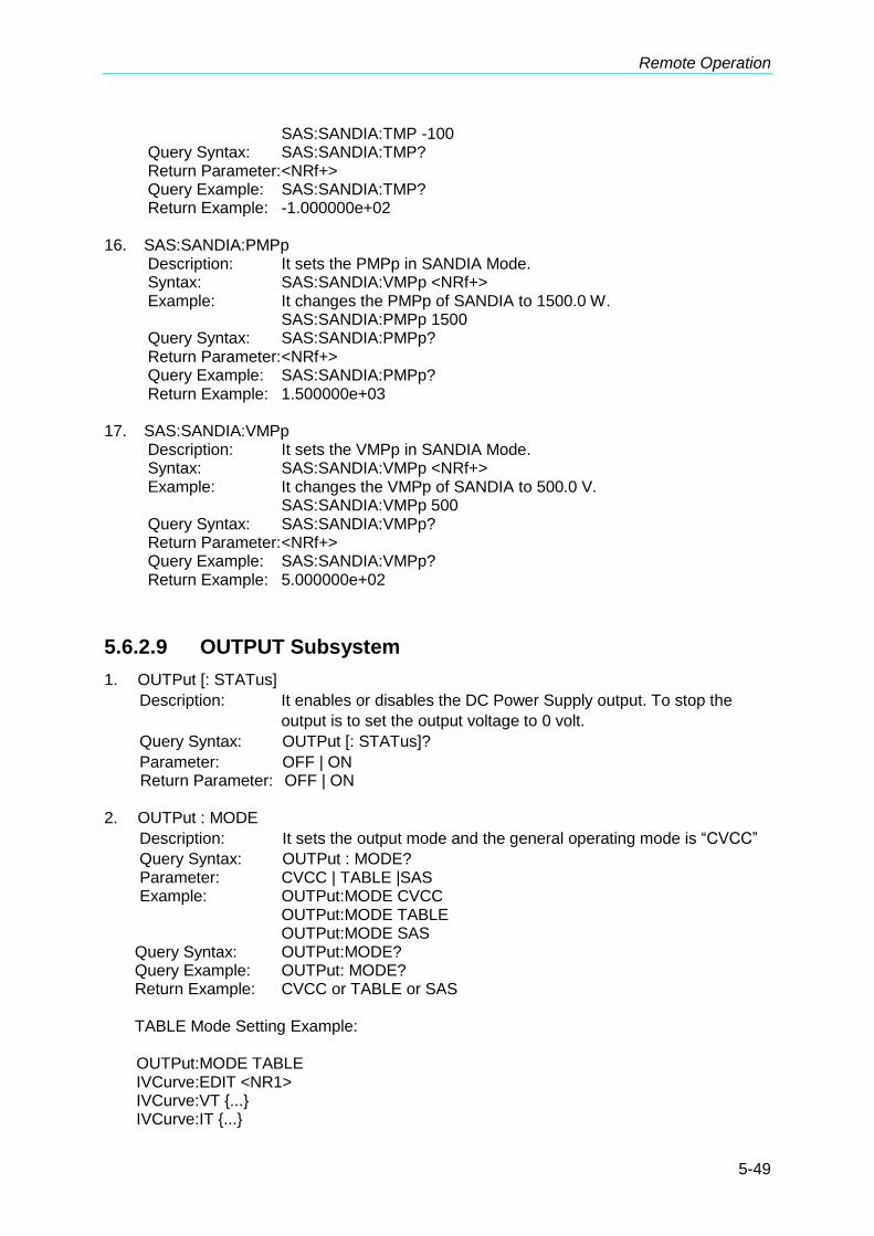
Remote Operation
5-49
SAS:SANDIA:TMP -100 Query Syntax: SAS:SANDIA:TMP? Return Parameter: <NRf+> Query Example: SAS:SANDIA:TMP? Return Example: -1.000000e+02
16. SAS:SANDIA:PMPp
Description: It sets the PMPp in SANDIA Mode. Syntax: SAS:SANDIA:VMPp <NRf+> Example: It changes the PMPp of SANDIA to 1500.0 W.
SAS:SANDIA:PMPp 1500 Query Syntax: SAS:SANDIA:PMPp? Return Parameter: <NRf+> Query Example: SAS:SANDIA:PMPp? Return Example: 1.500000e+03
17. SAS:SANDIA:VMPp
Description: It sets the VMPp in SANDIA Mode. Syntax: SAS:SANDIA:VMPp <NRf+> Example: It changes the VMPp of SANDIA to 500.0 V.
SAS:SANDIA:VMPp 500 Query Syntax: SAS:SANDIA:VMPp? Return Parameter: <NRf+> Query Example: SAS:SANDIA:VMPp? Return Example: 5.000000e+02
5.6.2.9 OUTPUT Subsystem
1. OUTPut [: STATus]
Description: It enables or disables the DC Power Supply output. To stop the
output is to set the output voltage to 0 volt.
Query Syntax: OUTPut [: STATus]?
Parameter: OFF | ON Return Parameter: OFF | ON 2. OUTPut : MODE
Description: It sets the output mode and the general operating mode is “CVCC”
Query Syntax: OUTPut : MODE? Parameter: CVCC | TABLE |SAS Example: OUTPut:MODE CVCC OUTPut:MODE TABLE OUTPut:MODE SAS
Query Syntax: OUTPut:MODE? Query Example: OUTPut: MODE? Return Example: CVCC or TABLE or SAS
TABLE Mode Setting Example:
OUTPut:MODE TABLE IVCurve:EDIT <NR1> IVCurve:VT {...} IVCurve:IT {...}

Programmable DC Power Supply (with Solar Array Simulation) 62000H Series Operating & Programming Manual
5-50
IVCurve:SELect <NR1> OUTPut ON

Remote Operation
5-51
5.6.2.10 SYSTEM Subsystem
1. SYSTem:ERRor? Description: It returns the error message and code of Power Supply. Query Syntax: SYSTem:ERRor? Query Example: SYST:ERR? Return Example: -203, “Data out of range”
Table 5-9
Code Error Message Code Error Message
0 "No error" -101 "Invalid character"
-102 "Syntax error" -103 "Invalid separator"
-104 "Data type error" -105 "GET not allowed"
-106 "Illegal parameter value" -108 "Parameter not allowed"
-109 "Missing parameter" -112 "Program mnemonic too long"
-113 "Undefined header" -121 "Invalid character in number"
-123 "Numeric overflow" -124 "Too many digits"
-131 "Invalid suffix" -141 "Invalid character data"
-148 "Character data not allowed" -151 "Invalid string data"
-158 "String data not allowed" -202 "Setting conflict"
-203 "Data out of range" -204 "Too much data"
-211 "Data stale" -224 "Self-test failed"
-225 "Too many errors" -226 "INTERRUPTED"
-227 "UNTERMINATED" -228 "DEADLOCKED"
-229 "MEASURE ERROR" -230 "Sequence overflow"
-231 "Sequence selected error"

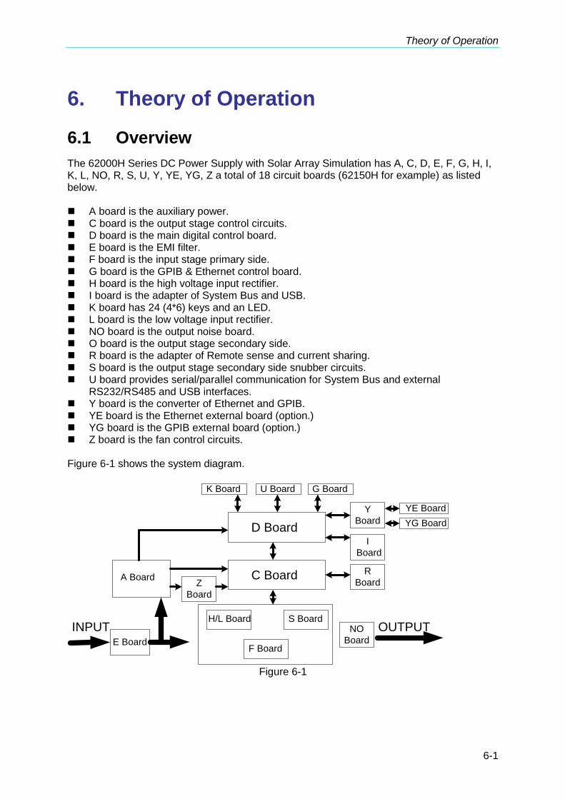
Theory of Operation
6-1
6. Theory of Operation
6.1 Overview
The 62000H Series DC Power Supply with Solar Array Simulation has A, C, D, E, F, G, H, I, K, L, NO, R, S, U, Y, YE, YG, Z a total of 18 circuit boards (62150H for example) as listed below. A board is the auxiliary power. C board is the output stage control circuits. D board is the main digital control board. E board is the EMI filter. F board is the input stage primary side. G board is the GPIB & Ethernet control board. H board is the high voltage input rectifier. I board is the adapter of System Bus and USB. K board has 24 (4*6) keys and an LED. L board is the low voltage input rectifier. NO board is the output noise board. O board is the output stage secondary side. R board is the adapter of Remote sense and current sharing. S board is the output stage secondary side snubber circuits. U board provides serial/parallel communication for System Bus and external
RS232/RS485 and USB interfaces. Y board is the converter of Ethernet and GPIB. YE board is the Ethernet external board (option.) YG board is the GPIB external board (option.) Z board is the fan control circuits. Figure 6-1 shows the system diagram.
INPUT
C BoardA Board
H/L Board
F Board
S Board
D Board
OUTPUT
K Board U Board G Board
Y
Board
I
Board
R
Board Z
Board
NO
Board E Board
YE Board
YG Board
Figure 6-1

Programmable DC Power Supply (with Solar Array Simulation) 62000H Series Operating & Programming Manual
6-2
Figure 6-2 shows the input stage structure.
R
S
T
G
SCR_ENABLE
From Digital Board
GND3
(Digital Board Ground)
V_DCBUS
GND_DCBUS
+18V2
(Fan Power)
Fan_Fault1
SCR Control Signal
J1
J2
J3
GND2
(Fan Power Ground)
+12V3
(Digital Board
Power)
220V INPUT: Capacitor in Parallel
380/440V INPUT: Capacitor in Series
EMI Filter
Auxiliary Power
+5VD +16VD
+12VO -12VO
+48V
I/P
STAGE
Figure 6-2
Figure 6-3 shows the output stage structure.
Dummy
Load
vo
vosvo
svo
O/P
Stage
Isolated
Driver
+12VO OGND
CV/CC
DectectADC
Converter
DAC
Converter
PWM
Current
Feedback
V_DCBUS
GNS_DCBUS
Voltage
Feedback
Figure 6-3
PWM control

Theory of Operation
6-3
Figure 6-4 shows the digital stage structure.
FPGA
DSP Memory
Linear
Regulator
+1.26VD
+3.3VD
+5VD
DGND
Isolated APG
Keyboard
K Board U Board
RS232/RS485
USB,System BUS
G Board
GPIB
Ethernet
Z Board
Fan signal
A Board
AC_Fault signal
C Board
F Board
Driver signal
SCR driver signal
+1.2VD
D Board
Figure 6-4
6.2 Function Description
6.2.1 I/P (PFC) Stage
1. The input stage is a bridge rectifier to rectify the 3-phase power source to DC.
2. The way input stage inhibits inrush current is to connect the input circuit to a 40 resistor in series during power-on to charge the input capacitor. Turn on the SCR after a few seconds and bypass this current limit resistor.

Programmable DC Power Supply (with Solar Array Simulation) 62000H Series Operating & Programming Manual
6-4
6.2.2 Auxiliary Power
1. The auxiliary power is the AC source input goes through the bridge rectifier and passes the flyback converter to get the desired output voltage.
2. The output of auxiliary power is divided into three types of isolate power and they are named FSGND, OGND and DGND based on their potential. The FSGND is the fan reference potential of output stage, while OGND is the reference potential of output stage and DGND is the reference potential of digital signal and communication interface.
6.2.3 Output Stage
1. The output stage structure is full bridge that uses PWM IC as the on/off switch and controlled by voltage mode.
2. There are two output modes -- Constant Voltage (CV Mode) and Constant Current (CC Mode) that switches automatically according to load state.
In Constant Voltage mode, following controls the IC detecting signal: (1) Output voltage; (2) The load actual voltage (remote sense) through output line. In Constant Current mode, following controls the IC detecting signal: (1) Output current.
3. The secondary side is one stage LC filter to lower down the ripple voltage and ripple current.
4. The action of Dummy load is Constant Current Source and the Dummy load current will adjust following the output voltage. Moreover, it will act if the programmed voltage is less than the present output. The output has OVP and when it exceeds the OVP voltage (16 bit DAC) set by the front panel, the output will be disabled.
6.2.4 Digital Circuit
1. The digital circuit control unit is composed of TI’s IC with the Lattice FPGA. 2. The power source 3.3V required by FPGA is got from +5VD. 3. The DSP required 3.3V and 1.26V power is got from +5VD. 4. The signal of analog program interface and digital circuit are isolated by the power
source of +16VD with the free-run flyback converter and linear regulator. 5. The TTL output is +5V level and the internal digital signal is +3.3V level, therefore there
are actions for level change.
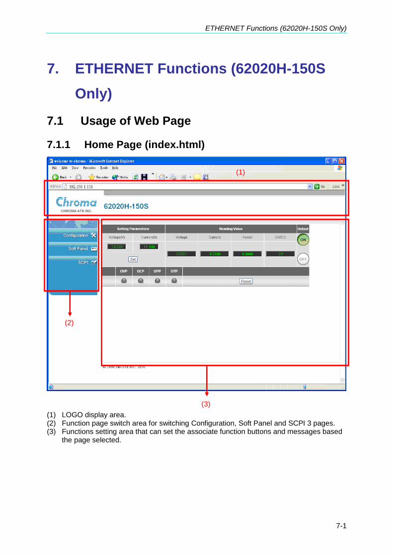
ETHERNET Functions (62020H-150S Only)
7-1
7. ETHERNET Functions (62020H-150S
Only)
7.1 Usage of Web Page
7.1.1 Home Page (index.html)
(1) LOGO display area. (2) Function page switch area for switching Configuration, Soft Panel and SCPI 3 pages. (3) Functions setting area that can set the associate function buttons and messages based
the page selected.
(2)
(1)
(3)

Programmable DC Power Supply (with Solar Array Simulation) 62000H Series Operating & Programming Manual
7-2
7.1.2 Configuration Page
When in Configuration page, the present network configuration will be read automatically and displayed on the message block [1].
(1) Message block [1]: It displays the network configuration for editing. The IP address,
Subnet mask, Default Gateway and DNS Server(s) are defined by TCP/IP Configuration Mode for editing. It is editable if set to Manual and unable to edit when set to Automatic.
(2) Refresh button: This function refreshes the configuration page by reading the associate info again to display on the message block [1].
(3) LAN Configuration Initialize button: It initializes the network to return to the factory
default without using the settings made in the message block [1]. A password confirmation will appear before executing this function. (No confirmation is required if the system password is blank.)
(2) (3) (4)
(1)
(5)
(6)
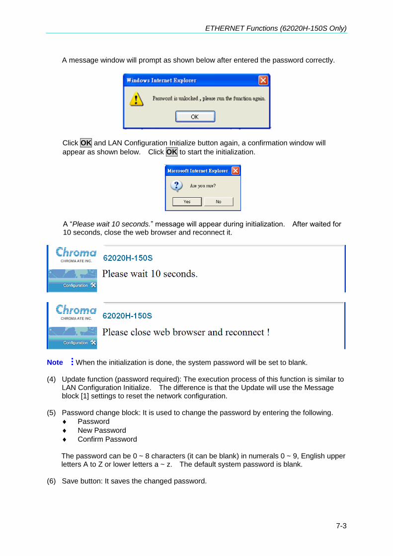
ETHERNET Functions (62020H-150S Only)
7-3
A message window will prompt as shown below after entered the password correctly.
Click OK and LAN Configuration Initialize button again, a confirmation window will
appear as shown below. Click OK to start the initialization.
A “Please wait 10 seconds.” message will appear during initialization. After waited for 10 seconds, close the web browser and reconnect it.
Note When the initialization is done, the system password will be set to blank. (4) Update function (password required): The execution process of this function is similar to
LAN Configuration Initialize. The difference is that the Update will use the Message block [1] settings to reset the network configuration.
(5) Password change block: It is used to change the password by entering the following.
Password
New Password
Confirm Password
The password can be 0 ~ 8 characters (it can be blank) in numerals 0 ~ 9, English upper letters A to Z or lower letters a ~ z. The default system password is blank.
(6) Save button: It saves the changed password.
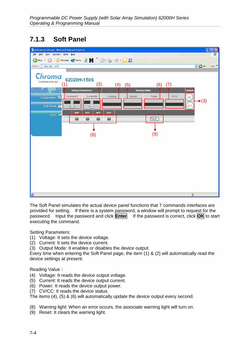
Programmable DC Power Supply (with Solar Array Simulation) 62000H Series Operating & Programming Manual
7-4
7.1.3 Soft Panel
The Soft Panel simulates the actual device panel functions that 7 commands interfaces are provided for setting. If there is a system password, a window will prompt to request for the
password. Input the password and click Enter. If the password is correct, click OK to start
executing the command. Setting Parameters: (1) Voltage: It sets the device voltage. (2) Current: It sets the device current. (3) Output Mode: It enables or disables the device output. Every time when entering the Soft Panel page, the item (1) & (2) will automatically read the device settings at present.
Reading Value:
(4) Voltage: It reads the device output voltage. (5) Current: It reads the device output current. (6) Power: It reads the device output power. (7) CV/CC: It reads the device status. The items (4), (5) & (6) will automatically update the device output every second. (8) Warning light: When an error occurs, the associate warning light will turn on. (9) Reset: It clears the warning light.
(1) (2)
(3)
(4) (5) (6) (7)
(8) (9)
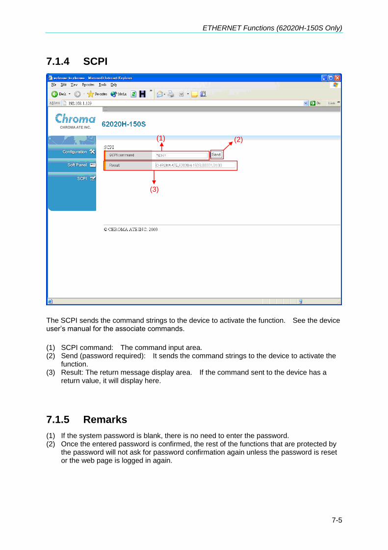
ETHERNET Functions (62020H-150S Only)
7-5
7.1.4 SCPI
The SCPI sends the command strings to the device to activate the function. See the device user’s manual for the associate commands.
(1) SCPI command: The command input area. (2) Send (password required): It sends the command strings to the device to activate the
function. (3) Result: The return message display area. If the command sent to the device has a
return value, it will display here.
7.1.5 Remarks
(1) If the system password is blank, there is no need to enter the password. (2) Once the entered password is confirmed, the rest of the functions that are protected by
the password will not ask for password confirmation again unless the password is reset or the web page is logged in again.
(1)
(3)
(2)
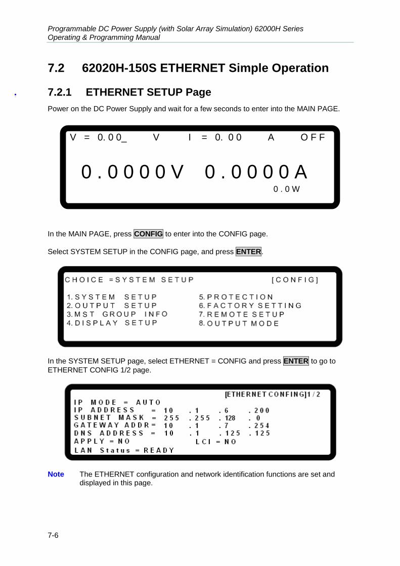
Programmable DC Power Supply (with Solar Array Simulation) 62000H Series Operating & Programming Manual
7-6
7.2 62020H-150S ETHERNET Simple Operation
7.2.1 ETHERNET SETUP Page
Power on the DC Power Supply and wait for a few seconds to enter into the MAIN PAGE.
V = 0. 0 0_ V I = 0. 0 0 A O F F
0 . 0 0 0 0 V 0 . 0 0 0 0 A 0 . 0 W
In the MAIN PAGE, press CONFIG to enter into the CONFIG page.
Select SYSTEM SETUP in the CONFIG page, and press ENTER.
In the SYSTEM SETUP page, select ETHERNET = CONFIG and press ENTER to go to
ETHERNET CONFIG 1/2 page.
Note The ETHERNET configuration and network identification functions are set and
displayed in this page.

ETHERNET Functions (62020H-150S Only)
7-7
7.2.2 Power Indicator & MAC Address Display
Continue to press ↓→ in ETHERNET CONFIG 1/2 page to skip the setting items to
ETHERNET CONFIG 2/2 page. This page shows the Power Status and MAC address.
Press ←↑ to return to ETHERNET CONFIG 1/2 page.
7.3 LAN Configuration Initialize (LCI) Function
Continue to press ↓→ in ETHERNET CONFIG 1/2 page until it reaches LCI, turn the rotary
knob to YES and press ENTER. The RUN LCI? page will appear.
Turn the rotary knob to YES and press ENTER to execute the LCI function.
It will show LAN Status = SETTING when the network is initializing. Once the settings are done, the display will return to LAN Status = READY.
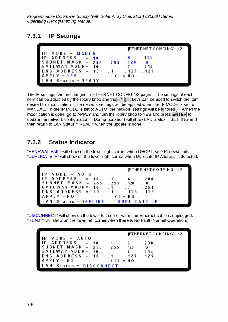
Programmable DC Power Supply (with Solar Array Simulation) 62000H Series Operating & Programming Manual
7-8
7.3.1 IP Settings
The IP settings can be changed in ETHERNET CONFIG 1/2 page. The settings of each
item can be adjusted by the rotary knob and the←↑ ↓→ keys can be used to switch the item
desired for modification. (The network settings will be applied when the IP MODE is set to MANUAL. If the IP MODE is set to AUTO, the network settings will be ignored.) When the
modification is done, go to APPLY and turn the rotary knob to YES and press ENTER to
update the network configuration. During update, It will show LAN Status = SETTING and then return to LAN Status = READY when the update is done.
7.3.2 Status Indicator
”RENEWAL FAIL” will show on the lower right corner when DHCP Lease Renewal fails. ”DUPLICATE IP” will show on the lower right corner when Duplicate IP Address is detected.
”DISCONNECT” will show on the lower left corner when the Ethernet cable is unplugged. ”READY” will show on the lower left corner when there is No Fault (Normal Operation.)

Self Test & Troubleshooting
8-1
8. Self Test & Troubleshooting
8.1 Overview
Follow the actions described in this chapter to inspect the instrument and troubleshoot the problem first when the 62000H Series DC Power Supply with Solar Array Simulation is unable to operate normally. Please consult the sales agent or distributor if the information provided in this manual is unable to resolve the problem.
8.2 Troubleshooting
Operation problems and suggestions for resolution:
Problem Cause Resolution
Bad measurement for V, I Feature swings due to aged components.
It needs calibration periodically. See section 3.3.7 Calibration.
Output is not within Accuracy SPEC.
Feature swings due to aged components.
It needs calibration periodically. See section 3.3.7 Calibration.
Over Temperature Protection (OTP)
1. The ambient temperature is too high.
2. The vent is blocked.
1. Operate the instrument within the temperature of 0 ~ 40°C.
2. Clear the vent.
Over Power Protection (OPP) The output power exceeds the spec.
Remove the over load or enlarge the OPP settings.
Over Current Protection (OCP)
The output current exceeds the spec. or OCP settings.
Remove the over load or enlarge the OCP settings.
Fan Fail Protection (FAN LOCK)
1. The fan is out of order. 2. The feedback circuit is
abnormal.
Consult with your local sales agent if it is unable to reset the protection state.
Input Error Protection 1 AC AFULT
The voltage of AC input line is either too low or too high.
Adjust the voltage if it exceeds the spec. when measuring the input voltage.
No output voltage 1. The output voltage feedback is abnormal.
2. The D/D power stage is damaged.
Consult with your local sales agent if it is unable to reset the protection state.
Over Voltage Protection (OVP)
The output voltage exceeds the spec. or OVP settings.
Check the OVP settings. Consult with your local sales agent if it is unable to reset the protection state.
Unable to control DC Power Supply via GPIB
1. The address of DC Power Supply is incorrect.
2. The GPIB cable is loose and fallen at rear.
1. Update the address. 2. Check the cable
connection and secure it with screws.
Current sharing cable connection error (C/S CABLE ERR.)
1. The current sharing cable is connected when used in series.
1. Check if the cables are connected correctly.
2. Consult with your local
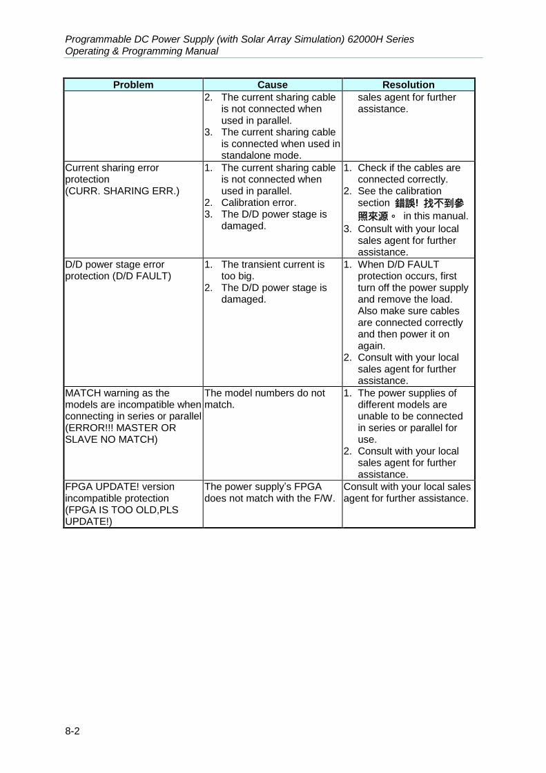
Programmable DC Power Supply (with Solar Array Simulation) 62000H Series Operating & Programming Manual
8-2
Problem Cause Resolution
2. The current sharing cable is not connected when used in parallel.
3. The current sharing cable is connected when used in standalone mode.
sales agent for further assistance.
Current sharing error protection (CURR. SHARING ERR.)
1. The current sharing cable is not connected when used in parallel.
2. Calibration error. 3. The D/D power stage is
damaged.
1. Check if the cables are connected correctly.
2. See the calibration section 錯誤! 找不到參
照來源。 in this manual.
3. Consult with your local sales agent for further assistance.
D/D power stage error protection (D/D FAULT)
1. The transient current is too big.
2. The D/D power stage is damaged.
1. When D/D FAULT protection occurs, first turn off the power supply and remove the load. Also make sure cables are connected correctly and then power it on again.
2. Consult with your local sales agent for further assistance.
MATCH warning as the models are incompatible when connecting in series or parallel (ERROR!!! MASTER OR SLAVE NO MATCH)
The model numbers do not match.
1. The power supplies of different models are unable to be connected in series or parallel for use.
2. Consult with your local sales agent for further assistance.
FPGA UPDATE! version incompatible protection (FPGA IS TOO OLD,PLS UPDATE!)
The power supply’s FPGA does not match with the F/W.
Consult with your local sales agent for further assistance.
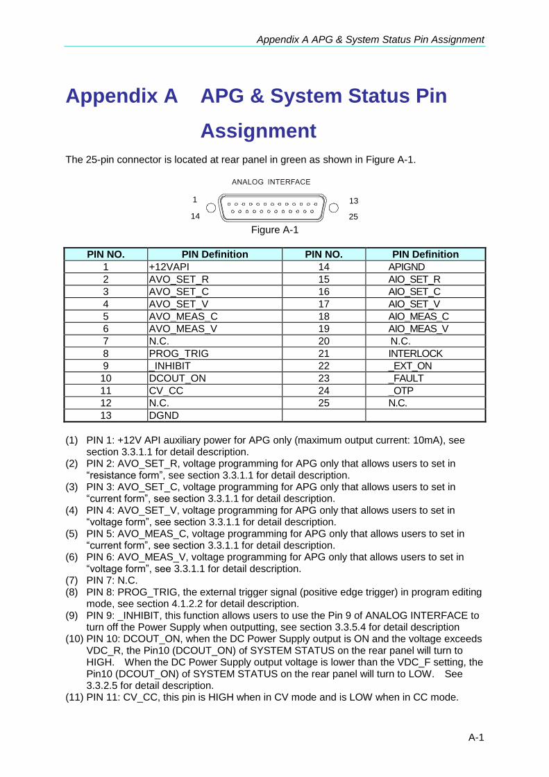
Appendix A APG & System Status Pin Assignment
A-1
Appendix A APG & System Status Pin
Assignment
The 25-pin connector is located at rear panel in green as shown in Figure A-1.
1
14
13
25 Figure A-1
PIN NO. PIN Definition PIN NO. PIN Definition
1 +12VAPI 14 APIGND
2 AVO_SET_R 15 AIO_SET_R
3 AVO_SET_C 16 AIO_SET_C
4 AVO_SET_V 17 AIO_SET_V
5 AVO_MEAS_C 18 AIO_MEAS_C
6 AVO_MEAS_V 19 AIO_MEAS_V
7 N.C. 20 N.C.
8 PROG_TRIG 21 INTERLOCK
9 _INHIBIT 22 _EXT_ON
10 DCOUT_ON 23 _FAULT
11 CV_CC 24 _OTP
12 N.C. 25 N.C.
13 DGND
(1) PIN 1: +12V API auxiliary power for APG only (maximum output current: 10mA), see
section 3.3.1.1 for detail description. (2) PIN 2: AVO_SET_R, voltage programming for APG only that allows users to set in
“resistance form”, see section 3.3.1.1 for detail description. (3) PIN 3: AVO_SET_C, voltage programming for APG only that allows users to set in
“current form”, see section 3.3.1.1 for detail description. (4) PIN 4: AVO_SET_V, voltage programming for APG only that allows users to set in
“voltage form”, see section 3.3.1.1 for detail description. (5) PIN 5: AVO_MEAS_C, voltage programming for APG only that allows users to set in
“current form”, see section 3.3.1.1 for detail description. (6) PIN 6: AVO_MEAS_V, voltage programming for APG only that allows users to set in
“voltage form”, see 3.3.1.1 for detail description. (7) PIN 7: N.C. (8) PIN 8: PROG_TRIG, the external trigger signal (positive edge trigger) in program editing
mode, see section 4.1.2.2 for detail description. (9) PIN 9: _INHIBIT, this function allows users to use the Pin 9 of ANALOG INTERFACE to
turn off the Power Supply when outputting, see section 3.3.5.4 for detail description (10) PIN 10: DCOUT_ON, when the DC Power Supply output is ON and the voltage exceeds
VDC_R, the Pin10 (DCOUT_ON) of SYSTEM STATUS on the rear panel will turn to HIGH. When the DC Power Supply output voltage is lower than the VDC_F setting, the Pin10 (DCOUT_ON) of SYSTEM STATUS on the rear panel will turn to LOW. See 3.3.2.5 for detail description.
(11) PIN 11: CV_CC, this pin is HIGH when in CV mode and is LOW when in CC mode.
Programmable DC Power Supply (with Solar Array Simulation) 62000H Series Operating & Programming Manual
A-2
(12) PIN 12: N.C. (13) PIN 13: DGND. (14) PIN 14: APIGND, +12V auxiliary power ground potential for APG only, see section
3.3.1.1 for detail description. (15) PIN 15: AIO_SET_R, current programming for APG only that allows users to set in
“resistance form”, see section 3.3.1.1 for detail description. (16) PIN 16: AIO_SET_C, current programming for APG only that allows users to set in
“current form”, see section 3.3.1.1 for detail description. (17) PIN 17: AIO_SET_V, current programming for APG only that allows users to set in
“voltage form”, see section 3.3.1.1 for detail description. (18) PIN 18: AIO_MEAS_C, current programming for APG only that allows users to set in
“current form”, see section 3.3.1.1 for detail description. (19) PIN 19: AIO_MEAS_V, current programming for APG only that allows users to set in
“voltage form”, see 3.3.1.1 for detail description. (20) PIN 20: N.C. (21) PIN 21: INTERLOCK, this function allows users to use the Pin 21 of ANALOG
INTERFACE to control the Power Supply for temporary OFF, see section 3.3.5.5 for detail description.
(22) PIN 22: _EXT_ON, this function allows users to use the Pin 22 of ANALOG INTERFACE to control the ON/OFF of Power Supply, see section 3.3.5.6 for detail description.
(23) PIN 23: _FAULT, this pin will turn to LOW when the protection signals described in section 3.3.5 occur.
(24) PIN 24: _OTP, this pin will turn to LOW when over temperature protection occurs. (25) PIN 25: N.C.

Appendix B List of Protection
B-1
Appendix B List of Protection
Protection Message on Panel Protection Message on Panel
Over voltage protect OVP Input voltage abnormal protect
AC FAULT
Over current protect OCP Remote sense abnormal protect
SENSE FAULT
Over power protect OPP CV TO CC mode change protect
CV TO CC FOLDBACK
Over temperature protect
OTP CC TO CV mode change protect
CC TO CV FOLDBACK
Fan fail protect FANLOCK Current sharing protect
CURR. SHARING ERR.
Current sharing cable connection error
C/S CABLE ERR. D/D power stage error protect
D/D FAULT
FPGA UPDATE! version incompatible protect
FPGA IS TOO OLD, PLS UPDATE!
MATCH warning as the models are incompatible when connecting in series or parallel
ERROR!!! MASTER OR SLAVE NO MATCH
REMOTE INHIBIT transition protect
IHB SAFETY INT.LOCK transition protect
SAFETY INT.LOCK
EXTERNAL ON/OFF transition protect
EXT

CHROMA ATE INC.
致茂電子股份有限公司
66 Huaya 1st Road, Guishan,
Taoyuan 33383, Taiwan
台灣桃園市 33383 龜山區
華亞一路 66 號
T +886-3-327-9999
F +886-3-327-8898
Mail: [email protected]
http://www.chromaate.com
Copyright by CHROMA ATE INC. All Rights Reserved. All other trade names referenced are the properties of their respective companies.


