55
The spirit of safety. Programmable Safety Systems PSS-Range PSS Standard Function Blocks MBS Sensor Signal Evaluation Version 1.0 Item No. 21 149-01
The spirit of safety.
Programmable Safety SystemsPSS-Range
PSS Standard Function BlocksMBS Sensor Signal Evaluation
Version 1.0Item No. 21 149-01

All rights to this manual are reserved by Pilz GmbH & Co. KG. Copies may be made forinternal purposes.
While every effort has been made to ensure that the information in this manual is accurate,no responsibility can be accepted for errors or omissions contained within it.
We reserve the right to amend specifications without notice. We are grateful for anyfeedback on the contents of this manual.
The names of products, goods and technologies used in this manual are trademarks of therespective companies.

1Modular Block System: Sensor Signal Evaluation
Contents
Introduction 1-1
MBS Modular Block System 1-2Categories / requirement classes 1-3Overview of manual 1-4Terminology 1-6
Overview 2-1
Software package 2-1Functionality 2-1Range 2-2
Safety 3-1
Safety guidelines 3-1Use of qualified personnel 3-1Warranty and liability 3-1Application guidelines 3-2Standards 3-3Fault detection 3-4Feasibility test 3-4Fault prevention 3-4
Intended Use 4-1
System software 4-1Intended use of the standard function blocks 4-2SB220: Evaluation of the inductive safety switch GM504S 4-4SB071: Initialisation of administration data blocks(DB015/DB016/DB017) 4-4

2
Contents
Modular Block System: Sensor Signal Evaluation
MBS Basics 5-1
Block design 5-1Structure 5-1Formal parameters and actual parameters 5-2Administration data blocks DB015, DB016 and DB017 5-3Structure of the administration data blocks 5-3Blocks contained in the administration data blocks 5-5Input parameter SSNR 5-7
Example 5-8Fault diagnostics 5-9Error types 5-9Fault diagnostics using the administration data blocks 5-10Temporary flag range in MBS blocks 5-11Output parameter ENBL 5-11Assignment of input and output parameters 5-12Minimum scan time 5-12Global parameters 5-13
Standard Function Blocks 6-1
SB220: Evaluation of the fail-safe inductive switchGM504S 6-1Block header 6-1Input parameters 6-1Output parameters 6-1Function 6-2Error messages 6-2Global parameters used in the administration blocks 6-2Blocks required 6-3Wiring of input and output parameters 6-4Test signal 6-4Feedback signal 6-5Monitoring times 6-6Reaction times 6-7Delayed setting of the enable 6-7

3Modular Block System: Sensor Signal Evaluation
Link Blocks 7-1
Check list 7-1
Examples 8-1
Applications and parameters of individual blocks 8-1Application example 8-2
Appendix 9-1
Assignment table: category and requirement class 1Standard function blocks: current versions 2

4
Contents
Modular Block System: Sensor Signal Evaluation

1-1Modular Block System: Sensor Signal Evaluation
This manual describes how to manage the standard function blocks in the“MBS Sensor Signal Evaluation” software package in accordance with theirintended use.Standard function blocks in the “MBS Sensor Signal Evaluation” packageare part of the Pilz MBS Modular Block System. They can be used in thefailsafe section of a PSS-range programmable safety system.
To fully understand this manual you will need to be conversant with theinformation found in the general documentation for the PSS-range (SystemManual, Installation Manual for the modular/compact PSS, PSS SW PGProgramming Manual/PSS WIN-PRO Programming Manual). In particular you should refer to the following documents from the SystemManual:
• Safety Manual
• FS System Description
• Error List
To fully understand the bus-specific requirements and correlations forSafetyBUS p applications you will need some knowledge of the design andmanagement of SafetyBUS p.
Knowledge of the safety regulations for the particular area of application isassumed.
You will find details to the function of the sensor in the manufacturer'soperating manual.
This installation manual is intended for instruction and should be retainedfor future reference.
Introduction

1-2
Introduction
Modular Block System: Sensor Signal Evaluation
MBS Modular Block System
Safety-related areas can be equipped with a multitude of safety devicessuch as E-STOPs, safety gates, light barriers etc. Safety devices arerequired in various quantities and combinations, depending on the objectrequiring protection. The Pilz MBS Modular Block System was developedto drive the various safety devices and to carry out process engineeringfunctions, helping users to save time and money.
The MBS consists of individual standard function blocks (SBs), which aregeared specifically towards the relevant safety device or processengineering function. It allows standard function blocks to be used in anycombination. The standard function blocks can be combined in anysequence (max. 600).
Standard function blocks are encoded by an authorised body so that theycannot be modified. If an encoded standard function block is used withinan application program, program testing may be restricted to the new partsof the program, considerably reducing the test time.

1-3Modular Block System: Sensor Signal Evaluation
Categories / requirement classes
EN 954-1 divides safety devices into categories.All standard function blocks are designed for the highest categorypermitted for the safety device to be monitored. If safety devices with lowercategories are to be monitored, input parameters may be assignedidentical inputs (further information can be found in the description for therelevant standard function block).
In process engineering, safety requirements must conform to DIN V 19250(Basic Safety Requirements for Measurement and Control ProtectionDevices).Requirement classes in accordance with DIN V 19250 may be referred tothe categories as per EN 954-1. The Appendix contains a table showingthe assignment of category and requirement class.

1-4
Introduction
Modular Block System: Sensor Signal Evaluation
Overview of manual
1 IntroductionThe chapter you are reading provides an introduction to the ModularBlock System (MBS). It is designed to familiarise you with thecontents, structure and specific order of this manual and also containsterminology definitions.
2 OverviewThis chapter provides information on the most important features ofthe software package and provides a brief overview of the applicationrange.
3 SafetyThis chapter must be read as it contains important information onsafety regulations.
4 Intended UseThis chapter must be read as it contains information on intended use.
5 MBS BasicsThis chapter explains the basic functions and safety requirements ofthe MBS.
6 Standard Function BlocksThis chapter explains the function of the standard function blocks inthe software package.
7 Link BlocksThis chapter is designed to help you link the standard function blocksinto your project and to commission the safety functions.
8 ExamplesThis chapter is designed to give an overview of how the standardfunction blocks may be applied and contains typical applicationexamples.
9 AppendixThe Appendix contains a table that explains the relationship betweencategories and requirement classes, plus a list that documents thecurrent version status of the standard function blocks.

1-5Modular Block System: Sensor Signal Evaluation
Definition of symbols
Information in this manual that is of particular importance can be identifiedas follows:
DANGER!
This warning must be heeded! It warns of a hazardous situation thatposes an immediate threat of serious injury and death and indicatespreventive measures that can be taken.
WARNING!
This warning must be heeded! It warns of a hazardous situation thatcould lead to serious injury and death and indicates preventivemeasures that can be taken.
CAUTION!
This refers to a hazard that can lead to a less serious or minor injury plusmaterial damage, and also provides information on preventive measuresthat can be taken.
NOTICEThis describes a situation in which the product or devices in its immediateenvironment could be damaged. It also provides information on preventivemeasures that can be taken.
INFORMATIONThis gives advice on applications and provides information on specialfeatures, as well as highlighting areas within the text that are of particularimportance.

1-6
Introduction
Modular Block System: Sensor Signal Evaluation
Terminology
• The term “input” is frequently abbreviated to “I” (e.g. I-Parameter).
• The term “output” is frequently abbreviated to “O” (e.g. O-Parameter).
• The term “PSS” is always used when the description is valid for allapplicable PSS programmable safety systems. If the description onlyrelates to a specific PSS series, the specific name for that series will beused (e.g. PSS 3000 or PSS SB 3056).
• In this manual, the system software “PSS WIN-PRO” is referred to as“programming device” or “PG”.
• The term "sensor" describes the inductive safety switch. Its signals areevaluated by the software package.
• "Sensor chain" is a number of sensors switched in series in accordancewith a sensor manufacturer specification. The chain requires only onetest signal, and it provides only one feedback signal, and therefore theblock sees it as an individual sensor.

2-1Modular Block System: Sensor Signal Evaluation
Software package
The “MBS Sensor Signal Evaluation” software package is part of the PilzMBS Modular Block System. The software package includes all therequired standard function blocks for the evaluation of the inductive safetyswitch (sensor) GM504S of ifm electronic GmbH.
Functionality
The SB220 is a standard function block for the evaluation of the fail-safeinductive switch GM504S from ifm up to and including category 4 inaccordance with EN 954-1, 03/97 and SIL3 in accordance with EN/IEC61508-3. The fail-safe switch can be connected directly to the inputs/outputs of the PSS, without the separate evaluation device.
The SB220 specifies the test signal for the safety switch and evaluates thefeedback signal from the sensor. In doing so, centralised and decentralisedPSS inputs can be used.All the wiring errors between the safety switch and the PSS arerecognized. If the fail-safe switch was switched in a safe state or if it is notdamped, or if a wiring error is detected, the enable output on the standardfunction block is immediately disabled and the error is entered in thecorresponding error data word for diagnostic purposes. The enable is setautomatically when the safety switch is damped and no errors are present.
Safety switches can be connected in series up to a maximum numberspecified by ifm (sensor chain). In this case, only one PSS input and onePSS output are required. SB220 can be used in programs with more than200 standard function blocks. To do this, SB071 must be used in OB120.
Standard function blocks in the “MBS Sensor Signal Evaluation” softwarepackage are used in the failsafe section of a PSS-range programmablesafety system.
Overview

Overview
2-2 Modular Block System: Sensor Signal Evaluation
Range
The software package consists of:
• The files for the software package on CD and
• An operating manual:PSS Standard Function Blocks MBS Sensor Signal Evaluation, Version1.0
The software package on the CD contains the following standard functionblocks:
• SB220 GM504SEvaluation of the inductive safety switch GM504S from ifm(approved safety block)
• SB071 INIT_MBSInitialisation of the administration data blocks (DB015/DB016/DB017)(approved safety block)
• SB255 System blockSB255 is described in the PSS System Description
3-1Modular Block System: Sensor Signal Evaluation
Safety guidelines
These safety guidelines are an important part of this manual. Failure tokeep to these guidelines will render all warranty, guarantee and liabilityclaims invalid.
• All health and safety / accident prevention regulations for the particulararea of application must be observed.
• Before using one or more of the standard function blocks in this softwarepackage, you must perform a safety assessment in accordance with theMachinery Directive.
Use of qualified personnel
The safety system may only be assembled, installed, commissioned,operated, maintained and decommissioned by qualified personnel who,because they are:
• Qualified electrical engineers or
• Have received training from qualified electrical engineers
are suitably experienced to operate units, systems, plant and machinery inaccordance with general standards and guidelines for safety technology.
Warranty and liability
All claims to warranty and liability will be rendered invalid if:
• Standard function blocks are used contrary to the purpose for which theywere intended
• Damage can be attributed to not having followed the guidelines in themanual
• Operating personnel are not suitably qualified.
Safety

3-2
Safety
Modular Block System: Sensor Signal Evaluation
Application guidelines
• The instructions given in the “Safety Manual” and in the “InstallationManual” must be followed.
• Please read the information in Chapter 4 regarding the intended use ofthese blocks.
• The use of Pilz SBs does not detract from the fact that it is theresponsibility of the user to design appropriate safety systems for plant,machinery and software.
• It is the users' responsibility to determine their application requirementsby carrying out a detailed risk analysis, which should take into accountrelevant regulations and standards, etc.
WARNING!
Please note: To achieve the corresponding category or requirement class,the whole system including all safety-related components (parts, devices,user program etc.) must be included in the assessment. For this reason,Pilz cannot accept liability for the correct classification into a category orrequirement class.

3-3Modular Block System: Sensor Signal Evaluation
Standards
To use the SBs correctly you will need to have a good knowledge of therelevant standards and directives. The following gives an overview of themost important standards:
• E-STOP circuits EN 418
• Safety of machinery - Two-hand controls EN 574
• Mechanical presses EN 692
• Hydraulic presses EN 693
• Hydraulic stamping and bending presses EN 12 622
• Machinery directive - basic terminology EN 292-1 and EN 292-2
• Printing and paper machinery prEN 1010
• Safety gates EN 1088
• Electrosensitive protective equipment EN 61 496-1
• Electrical equipment EN 60 204-1
• Machinery safety EN 954-1
• Basic Safety Requirements forMeasurement and Control Protection Devices DIN V 19 250
• Electrical equipment on firing plants prEN 50 156-1
Please note this is not an exhaustive list of safety standards and directives.

3-4
Safety
Modular Block System: Sensor Signal Evaluation
Fault detection
The detection of errors and defects is an important function of the PSS, inaddition to pure control tasks.
Information of the concept of error detection can be found in the PSSSystem Description.
WARNING!It is particularly important to detect open circuits and shorts within thesafety circuits (e.g. two-hand, E-STOP etc.)
It is the responsibility of the user to select and apply an appropriate faultdetection system.
Feasibility test
Redundant input devices for safety functions must undergo a feasibilitytest within the application program.
The plant must be stopped immediately if a feasibility error occurs. Similartests will also be required for other input devices.If safety valves have feedback contacts, these must be evaluatedaccordingly.
Fault prevention
Not all potential faults can be detected and managed. Such faults must beexcluded by suitable wiring.
Additional information on how to exclude potential errors can be found inthe BIA Handbook (BG Institute for Occupational Safety, St Augustin) or inthe directive VDI 2854 (safety requirements on automated manufacturingsystems).

4-1Modular Block System: Sensor Signal Evaluation
Use
The software package “MBS Sensor Signal Evaluation” is designed for usewithin the failsafe section of the PSS-range of programmable safetysystems.
INFORMATIONUse of standard function blocks outside the specifications described herewill be deemed improper use.
INFORMATIONAlways use the current version of a standard function block. Pleaseensure you refer to the Appendix, sections entitled “Standard functionblocks: current versions” and the amendment list.
System software
The software package “MBS Sensor Signal Evaluation” can be used withthe PSS WIN-PRO system software.
Further information is available in the programming manual for “PSS WIN-PRO”.
Intended Use

4-2
Intended Use
Modular Block System: Sensor Signal Evaluation
Intended use of the standard function blocks
WARNING!
The SB220 may only be used in combination with the fail-safe inductiveswitch GM504S of ifm Syntron GmbH. Applications with other sensorsare not permitted.
WARNING!
Category 4 in accordance with EN 954 can only be achieved under thecondition that the fail-safe switch is cyclically damped and undamped, andthat the fail safe switch is kept in a damped state most of the time.
WARNING!
If SB220 is used to lock hazardous machine functions (e.g. a safety gateapplication), the setting of the enable of the SB220 (output parameterPULS) must not start the hazardous machine functions.The enable must be evaluated by the monitoring function provided for theapplication, e.g. by the block SB064 S-GATE safety gate application. Onlythe monitoring function may trigger the start of the hazardous machinefunction.
WARNING!
You must consider the resulting reaction times. The reaction timesconsist of the reaction times of the fail-safe switch (see manufacturer’sdetails) and the PSS.The reaction time of the PSS depends on half the time period of the testsignal (output parameter PULS) and the tolerance for the monitoring of thefeedback signal. Using the resulting reaction time you must assesswhether the combination SB220 with a fail-safe switch is technicallysafe for a certain application.

4-3Modular Block System: Sensor Signal Evaluation
NOTICE
It is not permitted to use dual-pole outputs (e.g. outputs ofPSS(1) DI(2)O Z) for the test signal to the fail-safe switch!
WARNING!
It is not permitted to use outputs that can be configured as test pulseoutputs (e.g. outputs of the PSS(1) DI(2)O T) for the test signal to thesafety switch. Detection of shorts between contacts is not effective withthese outputs.The safety switch cannot drive the constant logic ’1’ signal with theseoutputs. Error detection then is no longer possible.
NOTICEIt is absolutely necessary to test beforehand in each application whethershorts between contacts are recognized by the PSS.
CAUTION!
Shorts between contact between the individual test signals can notbe detected.If several test signals are used, e.g. when the safety switch is notconnected in series, but if it is connected to the PSS individually with anown test signal each, it must be possible to exclude this wiring error.This is possible by e.g. laying cables to the safety switches outside thecontrol cabinet separate from each other.

4-4
Intended Use
Modular Block System: Sensor Signal Evaluation
SB220: Evaluation of the inductive safety switch GM504S
The SB220 is used to evaluate the fail-safe inductive switch GM504S ofifm electronic Syntron GmbH. The switch is called “sensor” in this manual.The building block can evaluate a max. of 1 sensor or sensor chain (seeterminology definitions in chapter 1, Introduction).The bock can be connected to centralised input/output modules and toSafetyBUS p modules.
SB071: Initialisation of administration data blocks (DB015/DB016/DB017)
SB071 is used to calculate the global parameters, depending on the setminimum scan time (see also under “Minimum Scan Time” in Chapter 5).The global parameters DW1001 ... DW1023 in the administration datablocks DB015, DB016 and DB017 are initialised using SB071.
Function:
• Reads in the set minimum scan time from DB002 (configurator)
• Calculates the cycles based on the times transferred in the parameters
• Enters the calculated values into the administration data blocks

5-1Modular Block System: Sensor Signal Evaluation
Block design
Structure
Safety-related areas can be equipped with a multitude of safety devicessuch as (e.g. E-STOPs, safety gates, light barriers). These safety devicesare used in various quantities and combinations, depending on the objectrequiring protection.
The Modular Block System (MBS) is made up of individual standardfunction blocks. A standard function block is geared towards therequirements of specific safety devices (e.g. monitoring an E-STOP button,safety gate monitoring).
A standard function block must be assigned to each safety device in orderfor it to be evaluated and monitored using the MBS. This procedureenables any combination of individual safety devices to be evaluated andmonitored. The standard function blocks can be combined in any sequencewithin the user program (max. 600).
One exception to this are standard function blocks used to drive andmonitor contactors or valves. For control engineering reasons, theseshould be called up at the end of the user program.
MBS Basics

5-2
MBS Basics
Modular Block System: Sensor Signal Evaluation
Formal parameters and actual parameters
Parameters can be set on the MBS standard function blocks. Formalparameters are established in the block header. The user must assign acorresponding actual parameter to each formal parameter. When thestandard function block is called up in the user program, the formalparameters will be replaced by the user-specific actual parameters.
Further information is available in the programming manual for “PSS WIN-PRO”.
Formal parameterPSS WIN-PRO: Pilz IL
X
B
W
DZ
Actual parameterPSS WIN-PRO: Pilz ILInput bit EOutput bit AFlag bit MInput byte EBOutput byte ABFlag byte MBConstant KBInput word EWOutput word AWFlag byte MWConstant KWData block DBTimer or counter

5-3Modular Block System: Sensor Signal Evaluation
Administration data blocks DB015, DB016 and DB017
Data blocks DB015, DB016 and DB017 are permanently specified withinthe Modular Block System (MBS).
These data blocks are common administration blocks for fault anddiagnostic data from the MBS standard function blocks and for block andparameter data that is required internally.
The administration data block DB015 must always be installed when usingMBS standard function blocks. Administration data blocks DB016 andDB017 are installed when necessary.The administration data blocks must always be installed with their fulllength of 1024 data words and they must always have read/write status.
NOTICEData blocks DB015, DB016 and DB017 should only be used as MBSadministration data blocks and not for other data.
Structure of the administration data blocks
The administration data blocks DB015, DB016 and DB017 have the samestructure.
Each standard function block in the user program has 5 data wordsavailable in one of the administration data blocks. These data words areused to back up the temporary flags from the standard function block (seesection entitled “Temporary flag range in MBS blocks”).
In each of the administration data blocks, the range DW0001 to DW1000 isdivided into 5 blocks, each with 200 data words (see Fig. 5-1).

5-4
MBS Basics
Modular Block System: Sensor Signal Evaluation
�����
�����
������
�����
�����������������
���� ������������
�����������������
�����������������
�����������������
��������������������
��������
�������
��������
�������
��������
�������
��������
�������
��������
�������
��������
�������
Fig. 5-1: Structure of the administration data blocks

5-5Modular Block System: Sensor Signal Evaluation
Blocks contained in the administration data blocks
Each standard function block occupies 1 data word per block (seeFig. 5-2). This means a max. of 200 safety devices (e.g. E-STOP 1, E-STOP 2, safety gate 1) can be managed per administration data block.
The PSS uses a standard function block’s SSNR to automatically generatethe corresponding data words (see section entitled “Input parameterSSNR”).
�����
�����
������
�����
�����
����
�����
�����
�����
��������������������
����������
���������
����������
����������
����������
�������������������� ����������� ���!������
Fig. 5-2: Contents of the administration data blocks

5-6
MBS Basics
Modular Block System: Sensor Signal Evaluation
DW0000 (DB015)If parameters for a standard function block’s input parameterSSNR are not within the permitted range, DW0000 of DB015will contain the incorrect SSNR parameter. The standardfunction block will not be enabled (output parameter ENBL= 0).If the SSNR=0, DW0000 of DB015 will contain the decimalvalue -1 or KH FFFF.
1st data block (DB015/DB016/DB017):DW 0001 ... DW0200 Bits for hardware and operator errors
The significance of the individual bits can be found in thedescription for the relevant standard function block (see sectionentitled “Fault diagnostics”).If a data word contains the value 0, no error has been found
2nd data block ... 5th data block (DB015/DB016/DB017):DW0201 ... DW1000
Data blocks 2 ... 5 are used for internal block data.
6th data block (DB015/DB016/DB017)DW1001 ... DW1023
Data block 6 contains the global parameters (see sectionentitled “Global parameters”).

5-7Modular Block System: Sensor Signal Evaluation
Input parameter SSNR
MBS standard function blocks have input and output parameters which canbe adapted to suit the respective control configuration. The inputparameter SSNR (safety subroutine number) is available on all MBSstandard function blocks. It is required to manage the administration datablocks DB015, DB016 and DB017.
INFORMATIONMBS standard function blocks may differ in terms of the permitted valuerange for the SSNR. The following value ranges are possible for the SSNR:
• Value range of input parameter SSNR: 1 ... 200(byte constant type: KB001 ... KB200)
• Value range of input parameter SSNR: 1 ... 600(word constant type: KF000001 ... KF000600)
The valid value range for the SSNR of a standard function block isdocumented in the standard function block description.
The input parameter SSNR determines the administration data block plusthe 5 data words assigned in the administration data block of thecorresponding safety device (1 DW per block). The administration datablocks are assigned the following SSNR ranges:
• SSNR 001 ... 200: DB015
• SSNR 201 ... 400: DB016
• SSNR 401 ... 600: DB017
The one data word per block is generated automatically internally (SSNR +offset).

5-8
MBS Basics
Modular Block System: Sensor Signal Evaluation
NOTICE
• One MBS standard function block must be used for each safety device.
• Each standard function block should be assigned its own SSNR.
• Make sure that each SSNR is assigned once only.If two SB calls have the same value for the SSNR, they will access thesame data word in the administration data block. This can lead tomalfunctions.
• Document the assignment of the safety device to the respective SSNR ofthe standard function block.
Example
Safety device 2 (E-STOP button) is monitored using SB061. The valueKB002 is assigned to input parameter SSNR of SB061.
The following DWs in DB015 are therefore assigned to safety device 2:
Block 1: DW0002Block 2: DW0202Block 3: DW0402Block 4: DW0602Block 5: DW0802
The user program has read-only access to these data words.
5-9Modular Block System: Sensor Signal Evaluation
Fault diagnostics
Error types
On programmable safety systems from the PSS-range, a distinction ismade between two types of errors. On the one hand there are errors whichare detected and evaluated through the PSS operating system, and on theother there are errors which are detected and evaluated through the userprogram. The reaction to these two types of errors is different.
Where errors are detected through the operating system, the FS section ofthe PSS will switch to a STOP condition and all outputs will be switched offsafely.
Where errors are detected through the user program, only the configurederror reaction will occur. Errors that are detected via an MBS standardfunction block belong to this second type of error.

5-10
MBS Basics
Modular Block System: Sensor Signal Evaluation
Fault diagnostics using the administration data blocks
Data words DW0001 ... DW0200 of an administration data block containthe error messages from the individual MBS standard function blocks (seeFig 5-3). 1 data word is reserved for each standard function block used.The assignment is made using the SSNR.
������
������
"""
�����#
������
������
������
"""
"""
"""
�����������
������
"""
�����#
������
������
������
"""
"""
"""
�����
�����$ ���
�����
���� ��
�����
���� ��$ ���
$%������
�����
���� ����$%�����#
�����
���� ����
������
������
"""
�����#
������
������
������
"""
"""
"""
Fig. 5-3: Managing the MBS error messages using the administration data blocks (example)

5-11Modular Block System: Sensor Signal Evaluation
Temporary flag range in MBS blocks
Internally, MBS blocks use the flags in the range M 64.00 ... M69.31 astemporary flags.
NOTICEWe recommend the following:
• Do not use flags from the temporary flag range for your own applications.Malfunctions may occur if you use the temporary flag range M64.00 ...M69.31 for your own applications.
• If it is absolutely necessary to use this flag range, under nocircumstances should you use the flags:- in alarm OBs- as input parameters for standard function blocks- as output parameters for standard function blocks- as global parameters
Output parameter ENBL
Many standard function blocks have an enable output FG/ENBL. Thisoutput parameter indicates the enable status of a standard function block.The enable status results from the standard function block’s check of theinputs.
ENBL = 1: No error found,function is enabled
ENBL = 0: An error has been found,function is not enabled.

5-12
MBS Basics
Modular Block System: Sensor Signal Evaluation
Assignment of input and output parameters
Input and output parameters should be assigned in accordance with thedetails given in the operating manual.
WARNING!If several unused output parameters are connected to the same flag,malfunctions may occur in the standard function blocks. If an unusedoutput has to be assigned a flag, make sure the output is assigned to aflag that is not used anywhere else in the program.
Minimum scan time
Most of the timer functions required within the blocks are performed usingcycle counters. This means that almost all the timers are available for usein applications.
INFORMATION
• If MBS blocks are used, a minimum scan time must always beentered in the configurator. Empirical values should be used.
• If the error message F-20/06 (error category/error number) appears inthe CPU display, you must amend the minimum scan time appropriately.This error message indicates that the minimum scan time has beenexceeded. The PSS must not be operated while this error message ispresent.
SB070 and SB071 automatically enter the minimum scan time in DW1022of the administration data blocks. In this way it is automatically available tothe MBS.
INFORMATIONPlease note that the times are imprecise. The lack of precision on times isdue to the cyclical processing of the user program. It is determined by thescan time of the respective user program.The following is generally valid:The greater the ratio of time value to scan time, the greater accuracy youwill have with the required times.

5-13Modular Block System: Sensor Signal Evaluation
Global parameters
Block 6 (DW1001 ... DW1023) of the administration data blocks containsglobal parameters. These are parameters that are valid for several blocks.For details of which global parameters a standard function block uses,please refer to the description of the individual standard function blocks.
The data words in block 6 must be initialised when the program is started(OB120) using SB070/SB071 (INIT_MBS).The abbreviations in brackets {... : ...} at the end of each data wordcorrespond to the parameters in SB071. The times that are also specifiedwithin the brackets are empirical values, unless stated otherwise.
DW1001 Number of cycles in the contact synchronisation time between 2N/O contacts or 2 N/C contacts (e.g. E-STOP button, reset key,etc.){CoSy : 50 ms}
DW1002 Number of cycles in the feedback loop’s reaction time to achange in the PSS output connected to the main contactor{RFbL : 100 ms}
DW1003 Number of cycles in the contact switchover time between a N/O and N/C contact (pushbutton){CS_B : 100 ms}
DW1004 Number of cycles in the contact switchover time between a N/O and N/C contact (relay){CS_R: 50 ms}
DW1005 Number of cycles in the machine clock time{MaCy : max. 30 s in accordance with EN 61496-1 sectionA.8.4, 06/98}
DW1006 Number of cycles in the permitted ESPE reaction time{ESPE : max. 150 ms in accordance with EN 61496-1 section5.2.4, 06/98}
DW1007 Reserved
DW1009 Reserved
DW1010 Reserved
DW1011 Reserved
DW1012 Reserved
5-14
MBS Basics
Modular Block System: Sensor Signal Evaluation
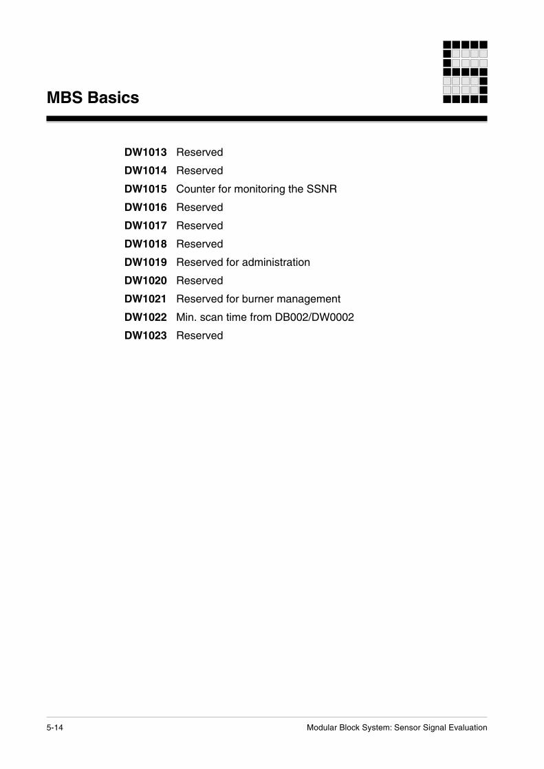
DW1013 Reserved
DW1014 Reserved
DW1015 Counter for monitoring the SSNR
DW1016 Reserved
DW1017 Reserved
DW1018 Reserved
DW1019 Reserved for administration
DW1020 Reserved
DW1021 Reserved for burner management
DW1022 Min. scan time from DB002/DW0002
DW1023 Reserved

Modular Block System: Sensor Signal Evaluation 6-1
Standard Function Blocks
SB220: Evaluation of the fail-safe inductive switch GM504S
Block header
Input parameters
•SSNR: Safety subroutine numberPermitted value range: 1 ... 600Format: Word constants KF000001 ... KF000600(see sections in Chapter 5 entitled “Administration data blocksDB015, DB016 and DB017” and “Input parameter SSNR”).
• IN: Feedback signal from fail-safe switch GM504SConnect this input parameter with the output “A” of the fail-safeswitch.It is possible to connect an individual fail-safe switch or a seriesconnection of up to the max. number of fail-safe switchesspecified by the fail-safe switch manufacturer.
Output parameters
•ENBL: Enable flag bit (Enable)ENBL = 0: Error detected or fail-safe switch not dampedENBL = 1: The enable is given when the fail-safe switch isdamped and no error is present.
• PULS: Test signal for fail-safe switch GM504SConnect this output parameter with the input “TE” of the fail-safe switch.
SB220GM504S
W - SSNRX - IN
ENBL - XPULS - X

6-2 Modular Block System: Sensor Signal Evaluation
Standard Function Blocks
Function
• Creating a test signal to the fail-safe switch
• Monitoring the feedback signal from the fail-safe switch
• Detecting wiring errors between fail-safe switch and PSS
• Enable of the function monitored by the fail-safe switch when it is error-free
Error messages
Any fault that is detected will be stored in the corresponding error dataword (SSNR) of the administration data block (1st data block), until thefault has been fully dealt with.
• Error messages in the administration data block- Bit 00: No correct feedback signal present.
The feedback signal does not correspond to the test signal.The safety switch is not damped, or there is an error present,e.g. internal error in the fail-safe switch.Remedy: Check fail-safe switch and wiring, dampen fail-safeswitch.
- Bit 01: No minimum cycle time set.Remedy: Set minimum cycle time andload program again.
• Error messages on the CPU-display- E003 Administration data block not initialised
Remedy: Call SB071 in OB120
Global parameters used in the administration blocks
Global parameters are set in OB120 using SB071.
• DW 1022: Minimum PSS scan time

Modular Block System: Sensor Signal Evaluation 6-3
Blocks required
• DB015, DB016, DB017: Administration data blocksThe data blocks must consist of their total length of 1024 data words andhave READ/WRITE access (see section entitled “Administration datablocks” in Chapter 5).
• SB071: Initialisation of global parameters in DB015, DB016 and DB017
• SB255: For calling up the operating system

6-4 Modular Block System: Sensor Signal Evaluation
Standard Function Blocks
Wiring of input and output parameters
&��'������(�����
)*++�� ���
,���-.,�/-
0- +�,&'+��,
������
10
*
� ���������
1�����!(���
%���������!(���
2 �� �
/�� �
Test signal
The test signal generated by the block to the fail-safe switch (outputparameter PULS) is a rectangle signal, and half of its period lengthdepends on the minimum cycle time set as follows:
Half period length (in PSS cycles) = 75 / minimum cycle time set.
If the resulting half period length is below 55 ms, the number of cycles isincreased by one.
• Example 1:Minimum cycle time set is 10 ms.Half period length (in PSS cycles) = 75 / 10 = 7 cycles = 70 ms.
• Example 2:Minimum cycle time set is 45 ms.Half period length (in PSS cycles) = 75 / 45 = 1 cycle.
One cycle means half a period length of 45 ms. This is less than 55 ms,therefore the number of cycles in increased by one. Resulting half periodlength = 2 cycles = 90 ms.
Fig. 6-1: Wiring principle

Modular Block System: Sensor Signal Evaluation 6-5
• Example 3: Minimum cycle time set is 90 ms.Half period length (in PSS cycles) = 75 / 90 = 0 cycles.
Zero cycles means half a period length of 0 ms. This is less than 55 ms,therefore the number of cycles in increased by one.Resulting half period length = 1 cycle = 90 ms
Feedback signal
At the feedback input of the block (input parameter IN) a signal is expectedwith the same period length as the test signal sent by the block (outputparameter PULS). The feedback signal does not have to be simultaneousto the test signal, its can be phase-delayed. This means a feedback signalwith any delay is possible.
The monitoring of the feedback signal consists of a time measurement thatmeasures half the period length of the feedback signal. The resolution is aPSS cycle. If half the period length of the feedback signal deviates fromhalf the period length of the test signal, the enable (output parameterENBL) is reset.
If a minimum cycle time of below 30 ms is set, monitoring tolerates adeviation of half the period length of the feedback signal of up to ca. ± 50ms In this case, half the period length of the feedback signal can be ca. 50ms shorter or up to ca. 50 ms longer than half the period length of the testsignal.
Formula for the calculation of the tolerance period:
Tolerance period (in PSS cycles) = 30 / minimum cycle time set.
If the resulting half period length is below 25 ms, the number of cycles isincreased by one.
• Example 1: Minimum cycle time set is 10 ms.Tolerance period (in PSS cycles) = 30 / 10 = 3 cycles = ± 30 ms.
• Example 2: Minimum cycle time set is 20 ms.Tolerance period (in PSS cycles) = 30 / 20 = 1 cycle.
One cycle means a tolerance time of 20 ms. This is less than 25 ms,therefore the number of cycles in increased by one. Resulting toleranceperiod length = 2 cycles = ± 40 ms.

6-6 Modular Block System: Sensor Signal Evaluation
Standard Function Blocks
Monitoring times
Below you find some examples for the monitoring times of the feedbacksignal:
• Example 1:Minimum cycle time set is 10 ms- Half period length test signal = 75 / 10 = 7 cycles = 70 ms- Set value half period length feedback signal = 70 ms- Tolerance period monitoring feedback signal = 30 / 10 = 3 cycles =
30 ms
������
#����
1�������,���"""�3�����
������
4����
Fig. 6-3: Set behaviour of the feedback signal in example 1
• Example 2:Minimum cycle time set is 90 ms- Half period length test signal = 75 / 90 = 0 cycles +1 cycle
= 90 ms- Set value half period length feedback signal = 90 ms- Tolerance period monitoring feedback signal = 0 ms
Fig. 6-4: Set behaviour of the feedback signal in example 2

Modular Block System: Sensor Signal Evaluation 6-7
Reaction times
The reaction time of the overall system PSS with fail-safe switch in case ofan error or an undamping of the fail-safe switch consists of the followingtimes:
• Reaction time of the fail-safe switch (see manufacturer’s details) plus
• half period length of the test signal plus
• Tolerance time in the monitoring of the feedback signal plus
• Imprecision of the PSS, i.e. the time that elapses until an event ispresent in the process image of the inputs, and until it can be processedby the program.
• Example: Minimum cycle time set is 20 ms- Half period length of the test signal = 60 ms- Tolerance time in the monitoring of the feedback signal = 40 ms
The reaction time of the fail-safe switch and the imprecision of the PSSneed to be added to the 100 ms.
Delayed setting of the enable
The enable is only set when the SB220 receives a correct feedback signalover a time period of 5 pulse edges (see section “Feedback signal”)
6-8 Modular Block System: Sensor Signal Evaluation
Standard Function Blocks
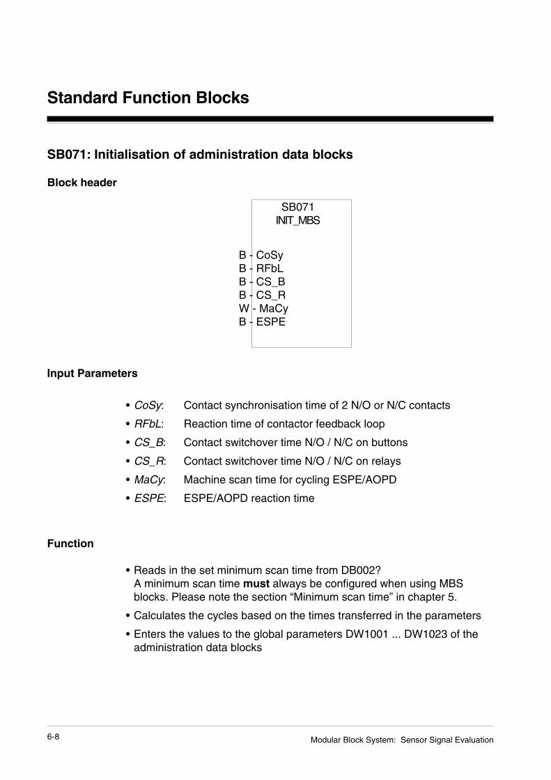
SB071: Initialisation of administration data blocks
Block header
SB071INIT_MBS
B - CoSyB - RFbLB - CS_BB - CS_RW - MaCyB - ESPE
Input Parameters
• CoSy: Contact synchronisation time of 2 N/O or N/C contacts
• RFbL: Reaction time of contactor feedback loop
• CS_B: Contact switchover time N/O / N/C on buttons
• CS_R: Contact switchover time N/O / N/C on relays
• MaCy: Machine scan time for cycling ESPE/AOPD
• ESPE: ESPE/AOPD reaction time
Function
• Reads in the set minimum scan time from DB002?A minimum scan time must always be configured when using MBSblocks. Please note the section “Minimum scan time” in chapter 5.
• Calculates the cycles based on the times transferred in the parameters
• Enters the values to the global parameters DW1001 ... DW1023 of theadministration data blocks

Modular Block System: Sensor Signal Evaluation 6-9
Table for setting the parameters of the global parameters:
INFORMATION• All times should be entered in ms.
• The values suggested are standard values. If your plant does not runstably using these values, you can work out the values to suit your plantas follows:- Select the standard value as a starting point.- Increase this value by appropriate time intervals until your plant runs
stably.
Input Parameters in Limits proposed valuesParameters Administration-DB in [ms] in [ms]CoSy DW 1001 0 ... 255 50RFbL DW 1002 0 ... 255 100CS_B DW 1003 0 ... 255 100CS_R DW 1004 0 ... 255 50MaCy DW 1005 0 ... 30 000 30 000 in acc. with
EN 61-496-1A.8.4
ESPE DW 1006 0 ... 255 150 in acc. withEN 61-496-1
reserved DW 1007DW 1008DW 1009
reserved DW 1010DW 1011DW 1012DW 1013DW 1014
reserved DW 1015DW 1016DW 1017DW 1018
reserved DW 1019 Administrationreserved DW 1020reserved DW 1021reserved DW 1022 min. cycle time DB002/DW0002reserviert DW 1023
6-10 Modular Block System: Sensor Signal Evaluation
Standard Function Blocks
Please note:Entering excessively high time values for monitoring will reduce the levelof safety on your plant.
If you are using Type 2 ESPE/AOPDs, the maximum value you mayenter for the ESPE parameter is a maximum value of 150 ms (EN61496-1).
• The number of cycles calculated is rounded down and is transmitted tothe data words of the administration blocks.
• The SB must be called once only as the PSS starts up(e.g. in the OB 120).
Error messages
• none
Blocks required
• OB120
• DB015/DB016/DB017: Administration data blocksThe data blocks must consist of its total length of 1024 data words. Thedata blocks must be declared READ/WRITE.

7-1Modular Block System: Sensor Signal Evaluation
Check list
• Safety regulations- Which safety regulations need to be met?- Aid: Relevant standards and regulations.
• Selecting standard function blocks- Which safety devices or process functions need to be supported?
Aid: Consult plant and machinery plans.- Which standard function blocks should be used?
Aid: Consult sample programs in Chapter 8.- Is the contact arrangement on the operator elements suitable for the
standard function blocks?- Does the PSS have the correct I/O arrangement?
• Start up the failsafe section of the programming device- Enter password.
• Load project into programming device- Aid: Use “Change Project” from the project menu.
• Import all the blocks you need into the project- Aid: Use “Import” from the project menu.
• Link the project allocation table to the block allocation table- Aid: Use “Import” from the project menu.- Does the allocation table contain all the operands and tags?
Tip: Logic signals may be linked symbolically.
• Adapt the allocation table to the wiring plan- Adapt the I/Os in the allocation table.
Aid: Allocation table editor.- Keep reserved flags free (do not use for your own applications).
• Configure system- Call up the configurator- Enter the set layout configuration- Enter the test pulse allocation- Enter preliminary run times for test purposes.
These can be optimised during commissioning.- Enter a minimum scan time.- If test pulses are to be connected to the 3 ms inputs (E x.16 ... E
x.31): Make sure the DI test time is set correctly.
Link Blocks

7-2
Link Blocks
Modular Block System: Sensor Signal Evaluation
• Establish the sequence in which the blocks will be called up- MBS blocks must be run through as part of each cycle.- Aid: Flow chart and listing.
• Create a supervisory (master) block- The master block should be either a PB or an FB
(if parameters are required: FB).- Call up the blocks in the correct sequence and set parameters for
them° Assign a different number to each block SSNR (1 ... 600)° Document the SSNR you have used° If necessary, combine the enable output parameters (FG/ENBL) into
suitable groups by means of a logic AND-operation.- Remember to take into account any links which have already been
made.- Enter details on the operation of the selected fault indicator
• Import / set up DB015 or DB015/DB016/DB017 in the project- DB015/DB016/DB017 must always contain 1024 data words- DB015/DB016/DB017 must have READ/WRITE status
• Create OB120If necessary, add SB070 or SB071 call.
• Create OB101- Reset all enable flags (FG/ENBL) at the start of the OB or at the start
of the cycle. This way you can be sure that the FG flags are indeedset.

7-3Modular Block System: Sensor Signal Evaluation
INFORMATIONOn some blocks (e.g. E-STOP) the input parameter “SSNR” ismonitored (see the description of the relevant SB in Chapter 6).These blocks must be run through as part of each PSS cycle. Thefollowing commands should therefore be entered once only at theend of OB101:
DB015 ADW1015 I
- Call up the E-STOP standard function blocks directly in OB101 or, forexample, global call in an FB.
- Check:Have all the blocks required for the application been called up?
• Things to note when starting up the programTip:- On start up, the PSS clears all the flag words, outputs, timers and
counters in the FS section. All the necessary constants shouldtherefore be set when starting up the program.
• Link Project
INFORMATION- All safety devices should be checked to ensure they operate
correctly.- Short-circuits and open circuits should be simulated.

7-4
Link Blocks
Modular Block System: Sensor Signal Evaluation
Notes

8-1Modular Block System: Sensor Signal Evaluation
Applications and parameters of individual blocks
The following examples are designed to show the application andparameters of individual standard function blocks.
The voltage supply to the PSS and the reset input E 0.31 are not shown inthe wiring diagrams for the sake of clarity.
Many of the following diagrams state the category for which the circuitry isdesigned, in accordance with EN 954-1, 03/97. For details of how thisrelates to the corresponding AK requirement class (DIN V 19 250, 05/94),please refer to the table in the Appendix.
NOTICEIt is important to note that the categories stated refer exclusively to thePSS circuitry and the parameters set on the SBs.To achieve the corresponding category throughout the whole system, allsafety-related components/devices (e.g. E-STOP button, safety limit switchetc.), plus the whole of the application program must be considered in theassessment (approved SBs do not need to be tested).
Pilz cannot accept responsibility for classifying installations into particularcategories.
Examples
8-2
Examples
Modular Block System: Sensor Signal Evaluation
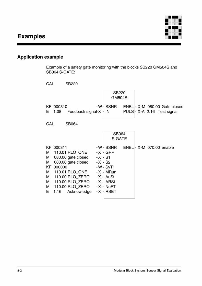
Application example
Example of a safety gate monitoring with the blocks SB220 GM504S andSB064 S-GATE:
CAL SB220
KF 000310 - -M 080.00 Gate closedE 1.08 Feedback signal- -A 2.16 Test signal
SB220GM504S
W - SSNRX - IN
ENBL - XPULS - X
CAL SB064
KF 000311 - -M 070.00 enableM 110.01 RLO_ONE -M 080.00 gate closed -M 080.00 gate closed -KF 000000 -M 110.01 RLO_ONE -M 110.00 RLO_ZERO -M 110.00 RLO_ZERO -M 110.00 RLO_ZERO -E 1.16 Acknowledge -
ENBL - X
SB064S-GATE
W - SSNRX - GRPX - S1X - S2W - SyTiX - MRunX - AuStX - ARStX - NoFTX - RSET

9-1Modular Block System: Sensor Signal Evaluation
Appendix
Assignment table: category and requirement class
In process engineering, safety requirements must conform toDIN V 19 250, 01/89 (Basic Safety Requirements for Measurement andControl Protection Devices).Requirement classes in accordance with DIN V 19 250, 01/89 may bereferred to the categories as per EN 954-1, 11/94.
Assignment as per requirements Assignment as per safety measures
Fig. 9-1: Assignment table
*1 This assignment cannot be definitive. It depends on the system and/orproduct.
*2 Depending on the anticipated extent of damage, requirement class 1may either be category 1 or may have no safety requirement.
������������
�������������
�� ����
�����������
�
��
������������������
������� ��
�
�
�
�����������������������
����
�
��
����
��

9-2
Appendix
Modular Block System: Sensor Signal Evaluation
Standard function blocks: current versions
INFORMATIONThis manual is intended exclusively for use with the standard functionblock versions listed below.
Older SB versions may differ from the description given in this manual.A description of the changes which have taken place when versions havebeen upgraded can be found in the amendment list below.
The version number can be determined from the information stated in theblock header of the SB (date and CRC).
SB No. Name Date CRC Version
SB220 GM504S 14.01.05 A11F 1.0
SB071 INIT_MBS 19.07.02 DF40 1.0
INFORMATION
Always use the current version of the relevant standard function block foryour application program.

... www
Hotline
Pilz GmbH & Co. KGSichere AutomationFelix-Wankel-Straße 273760 Ostfildern, GermanyTelephone: +49 711 3409-0Telefax: +49 711 3409-133E-Mail: [email protected]
www.pilz.com
+49 711 3409-444
In many countries we arerepresented by sales partners.
Please refer to our Homepagefor further details or contact ourheadquarters.
21 1
49-0
1-02
/05
Pri
nted
in G
erm
any


