54
Programmable Terminal NA-series Practice Guide Demonstration Screen for Safety CPU NA5-15□101□ NA5-12□101□ NA5-9□001□ NA5-7□001□ V447-E1-01

Programmable Terminal NA-series
Practice Guide
Demonstration Screen for Safety CPU
NA5-15□101□
NA5-12□101□
NA5-9□001□
NA5-7□001□
V447-E1-01

2
■ Introduction This guide provides reference information when using Safety CPU Unit IAG Library. It does not provide safety information. Be sure to obtain the NA-series Programmable Terminal User's Manuals, read and understand the safety points and other information required for use, and test sufficiently before actually using the equipment.

3
Terms and Conditions Agreements
Thank you for your usage of products of Omron Corporation (Omron). Without any special
agreements, these terms and conditions shall apply to all transactions regardless of who sells.
Definitions of Terms
- Omron product(s): Omron’s factory automation system devices, general control devices,
sensing devices, and electronic/mechanical components.
- Catalogues: Any and all catalogues (including “Best Components” and other catalogues),
specifications, instructions and manuals relating to Omron products, including electronically
provided data.
- Conditions: Use conditions, rating, performance, operating environment, handling procedure,
precautions and/or prohibited use of Omron products described in the catalogues.
- User application(s): Application of Omron products by a customer, including but not limited to
embedding/using Omron products into customer’s components, electronic circuit boards,
devices, equipment or systems.
- Conformity: (a)conformity, (b)performance, (c) no infringement of intellectual property of third
party , (d)compliance with laws and regulations, and (e) conformity to various standards of
Omron products in user applications.
Note about Descriptions
Understand the followings as to contents of the catalogues.
- Rating and performance is tested separately. Combined conditions are not warranted.
- Reference data is intended to be used just for reference. Omron does NOT guarantee that the
Omron Product can work properly in the range of reference data.
- Examples are intended for reference. Omron does not warrant the conformity in usage of the
examples.
- Omron may discontinue Omron products or change specifications of them because of
improvements or other reasons.
Note about Use
Adopt and use Omron products considering the following cautions.
- Use the product in conformance to the conditions, including rating and performance.
- Check the conformity and decide whether or not Omron products are able to be adopted.
Omron makes no guarantees about the conformity.
- Make sure in advance that electricity is properly supplied to Omron products and they are set
up rightly in your system for intended use.
- When you use Omron products, ensure the followings: (i) allowance in aspect of rating and
performance, (ii) safety design which can minimize danger of the application when the product
does not work properly, (iii) systematic safety measures to notify danger to users, and (ⅳ)
periodical maintenance of Omron products and the user application.
- Omron products are designed and manufactured as commodity for general industrial products.
For this reason, the usages (a) to (d) are to be unintended. Omron makes no guarantees on
Omron products, if you use Omron products for those purposes.
However, special applications that Omron expects or usages with especial agreement are

4
excluded.
(a) Applications requiring high-level safety (e.g. nuclear control facilities, combustion facilities,
aerospace and aviation facilities, railroad facilities, elevating facilities, amusement facilities,
medical facilities, safety devices or other applications which has possibility to influence lives or
bodies)
(b) Applications requiring high reliability (e.g. gas/water/electricity supply system, 24-hour
operating system, applications handling with rights/property, such as payment system)
(c) Applications in a harsh condition or environment (e.g. outdoor facilities, facilities with
potential of chemical contamination or electromagnetic interference, facilities with vibration or
impact, facilities on continual operation for a long period)
(d) Applications under conditions or environment which are not described in the catalogues
- Omron products in the catalogues are not intended to be used in automotive applications
(including two-wheel vehicles). Please DO NOT use Omron products in automotive
applications. Contact our sales personnel for automotive products.
Warranty
Warranty of Omron products is subject to followings.
- Warranty Period: One year after your purchase. However, except when there is a separate
statement in the catalogues.
- Coverage: Omron will provide one of the services listed below, on the basis of Omron’s
decision.
(a) Free repairing of the malfunctioning Omron products (except electronic/mechanical
components) at Omron maintenance service sites.
(b) Free replacement of the malfunctioning Omron products with the same number of
substitutes.
- Exceptions: This warranty does not cover malfunctions caused by any of the followings.
(a) Usage in the manner other than its original purpose
(b) Usage out of the conditions
(c) Usage out of Note about Use in these conditions
(d) Remodeling/repairing by anyone except Omron
(e) Software program by anyone except Omron
(f) Causes which could not be foreseen by the level of science and technology at the time of
shipment of the products.
(g) Causes outside Omron or Omron products, including force majeure such as disasters
Limitation of Liability
The warranty described in this Terms and Conditions Agreements is a whole and sole liability
for Omron products. There are no other warranties, expressed or implied. Omron and its
distributors are not liable for any damages arisen from or relating to Omron products.
Export Control
Customers of Omron products shall comply with all applicable laws and regulations of other
relevant countries with regard to security export control, in exporting Omron products and/or
technical documents or in providing such products and/or documents to a non-resident.
Omron products and/or technical documents may not be provided to customers if they violate
the laws and regulations.

5
Contents
Terms and Conditions Agreements ......................................................... 3
Contents ........................................................................................................................ 5
1 Related Manuals ............................................................................. 7
2 Precautions ..................................................................................... 8
3 Overview ......................................................................................... 9
3-1 Functions and Features ...................................................................................... 9
3-2 Demonstration Configuration .......................................................................... 10
3-3 Project File and Supporting Range .................................................................. 11
3-3-1 Project File ............................................................................................................................. 11
3-3-2 Supported Models and Specification .................................................................................... 11
4 Installation ..................................................................................... 12
4-1 Import Projects ................................................................................................. 13
4-2 Set the NA Clock ............................................................................................... 14
4-3 Add Devices ....................................................................................................... 17
4-3-1 Add External Devices ............................................................................................................ 17
4-3-2 Add Internal Devices ............................................................................................................. 18
4-4 Transfer Projects to NA .................................................................................... 19
5 Demonstration Procedure for Each Function ................................. 20
5-1 Monitor LEDs on Safety I/O ............................................................................. 20
5-2 Register and Confirm Safety Signature .......................................................... 21
5-2-1 Registration............................................................................................................................ 21
5-2-2 Confirmation .......................................................................................................................... 23
5-2-3 Screen Transition .................................................................................................................. 24
5-3 Display Data Logging Results .......................................................................... 25
5-3-1 Download of Data Log Setting File and Data Logging ....................................................... 25
5-3-2 Graphic Display ..................................................................................................................... 27
5-3-3 Measurement of Time between Two Points on the Graph .................................................. 29
5-3-4 Screen Transition: Downloading Data Log Setting File .................................................. 30
5-3-5 ScreenTransition: Graphic Display ...................................................................................... 31
5-4 Restore Safety Program at Site ........................................................................ 32
5-4-1 Download Restore File .......................................................................................................... 32
5-4-2 Restoring on Safety CPU Unit .............................................................................................. 34
5-4-3 Screen Transition: Safety Program Restoring ..................................................................... 36
6 Appendix: Specifications ................................................................ 37
6-1 Screen Overview ............................................................................................... 37
6-2 Screen Transition and Security Level ............................................................. 39
6-3 Detail Screen Specifications ............................................................................. 40
6-3-1 Menu Screen .......................................................................................................................... 40

6
6-3-2 I/O Table Screen .................................................................................................................... 41
6-3-3 Safety I/O LED Monitor Screen ............................................................................................ 42
6-3-4 Safety Signature Confirmation Screen ................................................................................ 43
6-3-5 Date Log File Selection Screen ............................................................................................. 44
6-3-6 Display Variable Selection Screen........................................................................................ 45
6-3-7 Data Log Display Screen ....................................................................................................... 46
6-3-8 Measurement Screen ............................................................................................................. 47
6-3-9 Restored File Download Screen ............................................................................................ 48
6-3-10 Data Log Setting File Download Screen ............................................................................ 49
6-3-11 Safety CPU Demo Movie Screen ........................................................................................ 50
6-3-12 Login Screen ........................................................................................................................ 51
6-3-13 Logout Screen ...................................................................................................................... 52
Revision History ........................................................................................................... 53

7
1 Related Manuals
Cat. No. Model Title
V117 NA5-15W[][][][]
NA5-12W[][][][]
NA5-9W[][][][]
NA5-7W[][][][]
Programmable Terminal User’s Manual (Hardware)
V118 NA5-15W[][][][]
NA5-12W[][][][]
NA5-9W[][][][]
NA5-7W[][][][]
Programmable Terminal User’s Manual (Software)
V120 NA5-15W[][][][]
NA5-12W[][][][]
NA5-9W[][][][]
NA5-7W[][][][]
Programmable Terminal Startup Guide
Z395 NX-SL5[][][]
NX-SI[][][][]
NX-SO[][][][]
NX-CSG[][][]
Safety Control Unit/Communication Control Unit
User's Manual
Z396 NX-CSG[][][] Communication Control Unit User's Manual Built-in
Function

8
2 Precautions
(1) When building an actual system, check the specifications of the component devices of the system,
use within the ratings and specified performance, and implement safety measures such as safety
circuits to minimize the possibility of an accident.
(2) For safe use of the system, obtain the manuals of the component devices of the system and check
the information in each manual, including safety precautions, precautions for safe use.
(3) It is the responsibility of the customer to check all laws, regulations, and standards that the system
must comply with.
(4) All rights reserved. No part of this publication may be reproduced, stored in a retrieval system, or
transmitted, in any form, or by any means, mechanical, electronic, photocopying, recording, or
otherwise, without the prior written permission of OMRON.
(5) The information in this guide is current as of June 2018.
It is subject to change without notice because of product’s update.
Special information in this document is classified as follows:
Precautions for Safe Use
Describes precautions on what to do and what not to do to ensure safe usage of the product.
Precoutions for Correct Use
Describes precautions on what to do and what not to do to ensure proper operation and
performance.
Additional Information
Additional information to read as required.
This information is provided to increase understanding or make operation easier.
Copyrights and Trademarks
Sysmac is the trademark or registered trademark of Omron Corporation in Japan and other
countries for Omron factory automation products.
Screenshots are used in accordance with Microsoft Corporation guidelines.
Windows and Visual Basic are the registered trademarks of Microsoft Corporation in the USA and
other countries.
EtherNet/IP is the registered trademark of ODVA.
Company names and product names in this document are the trademarks or registered trademarks
of their respective companies.

9
3 Overview
3-1 Functions and Features
We introduce a demonstration screen has that enables the functions of Safety CPU Unit to be used
on NA.
The demo screen makes settings possible without using Sysmac Studio in work sites. Even the
operator who does not know how to use the tools can acquire data.
In addition, since parts are prepared for each function, the designer’s man-hours can be reduced.
Implemented functions are as follows:
1) LED monitor function of Safety I/O Unit
2) Registration of safety signature information of Safety CPU Unit and Current Value Reading
function
3) Safety Data Log function
4) Restored file download function
In this demo screen, an NA accesses to Safety PLC and I/O directly to obtain necessary information.
It brings new features as described below.
■Easy introduction and start-up
A controller does not need to share global variables and as before. Also fine-tuning between
communication ladder programs, a controller, and HMI are not required. It enables the controller to
start up quickly.
■No disturbance in high-speed and high-precision.
A controller doesn't have a monitor and communication program for settings not originally related to
high-speed and high-precision control. It enables minimize the influence of tact on the control
program.
NA5 accesses to Safety
CPU and I/O Unit directly.

10
Safety CPU demo
configuration
IP Address 192.168.1.1
3-2 Demonstration Configuration
The operation is validated with the following components.
It is possible to connect another safety CPU configuration to the demonstration project.
Refer to 4-3-1 Add External Devices and 4-3-2 Add Internal Devices for the setting method.
Manufacturer Device Model Version
Omron Safety network controller NX-CSG320 Ver 1.00
Omron Indicator (HMI) NA5-12W101S
NA 1.10
Runtime 1.10.9 OS 7.1.2
Omron SysmacStudio SYSMAC-SE□□□□ Ver1.24
Omron PC (OS: Windows7)
Omron Safety CPU unit NX-SL5700
Omron Safety input unit NX-SID800 NX-SIH400
Omron Safety output unit NX-SOD400
Omron Digital input unit NX-ID4442
Digital output unit NX-OD4256
EtherNet/IP cable x2
Omron Switching hub W4S1-05B
11
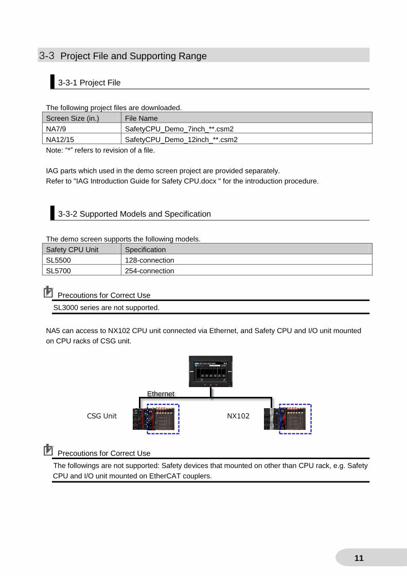
3-3 Project File and Supporting Range
3-3-1 Project File
The following project files are downloaded.
Screen Size (in.) File Name
NA7/9 SafetyCPU_Demo_7inch_**.csm2
NA12/15 SafetyCPU_Demo_12inch_**.csm2
Note: “*” refers to revision of a file.
IAG parts which used in the demo screen project are provided separately.
Refer to "IAG Introduction Guide for Safety CPU.docx " for the introduction procedure.
3-3-2 Supported Models and Specification
The demo screen supports the following models.
Safety CPU Unit Specification
SL5500 128-connection
SL5700 254-connection
Precoutions for Correct Use
SL3000 series are not supported.
NA5 can access to NX102 CPU unit connected via Ethernet, and Safety CPU and I/O unit mounted
on CPU racks of CSG unit.
Precoutions for Correct Use
The followings are not supported: Safety devices that mounted on other than CPU rack, e.g. Safety
CPU and I/O unit mounted on EtherCAT couplers.
Ethernet
CSG Unit NX102

12
4-2 Set the NA Clock
4-3
Add Devices
4-3-1 Add External Devices
4-1 Import Projects
4-3-2 Add Internal Devices
4-4 Transfer Projects to NA
転送
NA and controllers are
managed in one project.
NA and a controller are
managed in separate projects.
4 Installation
The installation procedure of Safety CPU demonstration screen is shown in the flowchart below.
It is necessary to register a Safety CPU to monitor in “4-3 Add Devices”. Make a registration of an
external device or internal device according to your project management.
Additional Information
In the step “4-3 Add Devices”, you can add the controller easily only by setting an IP address if you
don't need to share variables with NX102 or CSG for demonstration purposes only. Refer to “4-3-1
Add External Devices”.

13
4-1 Import Projects
1. Set the PC’s IP address to
192.168.1.100.
Make sure that the IP address of the
PC does not overlap with the IP
address of the devices that
configures the connected system.
2. Startup Sysmac Studio.
*Sysmac Studio Ver1.24 shall be
installed.
3. Select Import.
4. The dialog box shown on the
right appears. Select a project
file of the Safety CPU demo
screen and select Open.
5. The project file is imported
and opened automatically.

14
4-2 Set the NA Clock
This section describes the setting for NA’s clock.
Be sure to set the clock because the current time display on this demo screen and the update time (local
time) of Safety Signature function refer to the clock.
1. Power on NA.
2. In the top window of Multiview
Explorer, set the device to be
edited to NA5.
*If NA5 is already set, setting is not
necessary.
3. Click HMI – Communication
Setup.
4. Select Ethernet Connection via a
Hub and set the destination IP
address to 192.168.1.50.
If the NA's IP address is
different, change the setting in
System Menu or others.
Current time display
Update time
(local time)

15
5. Click OK.
6. Select the Online icon in the
Toolbar.
If the version of the NA is V1.10 or
less, upgrading is demanded
when you connect online.
Upgrade the current NA version
following to the dialog.
After upgrading is completed, the
NA is reset. Select Online in the
Toolbar again.
7. Click HMI – HMI Clock.
8. Select the proper time zone
according to the area where the
devices used. Then click Apply.
9. Click Yes.

16
10. After a restart, click
Synchronize with Computer -
Apply.
11. Click Close.
12. Click the Offline icon in the
Toolbar.

17
4-3 Add Devices
In this project file, it is necessary to register the Safety CPU to be monitored. There are two
methods: adding as an external device and as an internal device. NA can monitor multiple Safety
CPUs. The maximum number of registrable units is 16, including controllers to which the Safety
CPU is not connected.
4-3-1 Add External Devices
This section describes how to add devices to another project.
If there is no need to communicate between NX102/CSG and NA except monitoring the Safety PLC,
such as demonstrations, you onlt have to set the IP addredd to add the Safety CPU Unit. This
method is recommended.
1. Right-click Config/Setting –
Device Reference. Then Left-click
Add – External Device.
2. ExternalDevice0 is added.
Double-click it.
3. Click Device and select
NX-CSG320.
* NX102 is also available.
4. Enter any IP address.
The Safety CPU Unit to be
connected is added.

18
4-3-2 Add Internal Devices
In this section, how to add devices to a project is described. If you need communication and
display/operation screen other than this demo screen between NX102/CSG and NA (e.g. designing
an atuctual customer's equipment), the following procedure is recommended.
1. In the top window of Multiview
Explorer, set the device to be
edited to NA5.
* If NA5 is already set, setting is not
necessary.
2. Right-click the NA icon.
3. Left-click Add Device.
4. Set the device as shown on the
right and click OK. Select the
unit's version in use for
Version.
* NX102 is also available.
5. A controller is added. Implement
necessary settings.
The Safety CPU Unit to be
connected is added.

19
4-4 Transfer Projects to NA
1. Click Online in the Toolbar.
2. Click the Sync icon in the Toolbar.
3. When the Synchronization
Window is displayed, click
Transfer to Device to start
transfer.
4. When the transfer is completed,
press Close.
5. If the NA restarts and the initial
screen which was set in the project
file displayed, download is
completed.
※ Menu Screen is displayed for the
default setting.

20
5 Demonstration Procedure for Each
Function
5-1 Monitor LEDs on Safety I/O
LED status of Safety I/O unit can be checked on NA without opening the control panel. The
procedure is shown below.
Precoutions for Correct Use
It is not possible to monitor I/O status of Safety CPU Unit and ordinary I/O Unit.
1. Press Safety CPU Demo Screen.
2. I/O Table Screen for the
connected controller appears.
If six or more units are installed, press
the button ◀ or ▶ to move to the right
or left.
3. Press the I/O Monitor button for the
I/O you want to check.
The buttons for Slot No2 NX-SID800
are shown in the right.
4. The status of the selected I/O is
indicated.
Press the ◀ or ▶ buttons to see
other I/O units. The display is
automatically updated at 2-second
intervals. It is possible to update with
Manual Display Update button.

21
5-2 Register and Confirm Safety Signature
The safety CPU program should be always operating correctly throgh equipment design to its
operation. In this section, the procedure to check that the safety signature is not unintentionally
tampered from the status of machine design by using the NA at site at the time of startup is
described.
5-2-1 Registration
First, register the correct safety signature in NA when designing the equipment or changing its
safety program.
1. Press Safety Demo Screen.
2. Press the Signature View tab.
3. Press Registration.
4. Login Window appears. Enter the
followings:
User Name omron
Password omron123
5. Press the Login button.
22
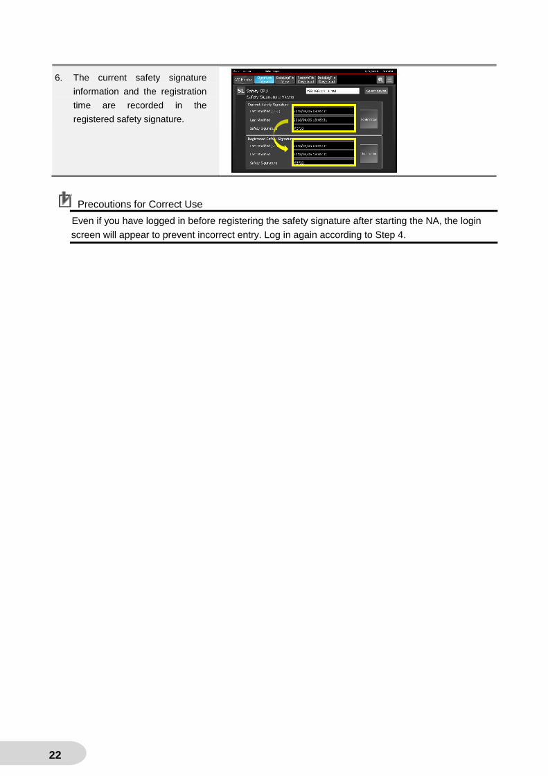
Precoutions for Correct Use
Even if you have logged in before registering the safety signature after starting the NA, the login
screen will appear to prevent incorrect entry. Log in again according to Step 4.
6. The current safety signature
information and the registration
time are recorded in the
registered safety signature.

23
5-2-2 Confirmation
This section shows how to acknowledge the status of the safety signature which registered in
accordance with the registration procedure in 5-2-1 Registration.
Register the safety signature before you read this section.
Additional Information
To save screen shots in a USB memory, press the NA Function Key 1.
1. Turn off the power of the Safety
CPU demo configuration and
turn it on again.
2. Press Safety Demo Screen.
3. Press the Signature View tab.
4. Confirm that Current Safety
Signature and Registered Safety
Signature are the same.
The same

24
5-2-3 Screen Transition
Initial state
Registration of safety signature
Completion of registration
Discordance of the safety
signatures
Registration error
Registered safety
signature

25
5-3 Display Data Logging Results
Safety CPU Unit can acquire log data based on Data Log Setting file generated by Sysmac Studio. This section describes how to download Data Log Setting files and to display the logging results in NA5 trend graph.
5-3-1 Download of Data Log Setting File and Data Logging
First, save the Data Log Setting file to the NA5 USB memory. Then transfer it to the memory card of NX102/CSG unit in which the Safety CPU Unit is installed.
1. Store the Data Log Setting file
created with Sysmac Studio in
the USB memory. Plug in the
memory into NA5.
2. Press Safety CPU Demo Screen.
3. Click the Data Log File View tab.
7. Login window appears. Enter the
followings:
Username omron
Password omron123
4. Press Login.
* Once you log in, it is not necessary
to log in for the second time or
later.

26
Precoutions for Correct Use
If you have logged in before downloading the Data Log Setting file, the login screen does not appear.
Press Data Log File View to go to the file download window.
5. Download screen is displayed.
Choose the file to download.
6. Press Download.
7. The filename to be downloaded is
displayed. Press the OK button.
8. Completion dialog window
appears. Press OK.
9. Press and hold the SERVICE
switch on the front of the Safety
CPU Unit. Release the finger
from the switch when the
seven-segment display on the
upper part of the unit indicates
as in the picture on the right.

27
5-3-2 Graphic Display
NA5 reads the results of data logging and diaplays them in a trend graph form.
1. Press Safety CPU Demo Screen.
2. Click the Data Log File View tab.
3. Select the datalog file to display.
Note: The data log files are listed
from latest to earliest of the
update date and time.
4. Press the Data Log Result View
button.
5. The variables that logged in the
file are listed. Select one to
display.

28
6. Press the Data Log Display
button.
7. The timing chart of the variable
which selected in the previous
step (Step 6).
29
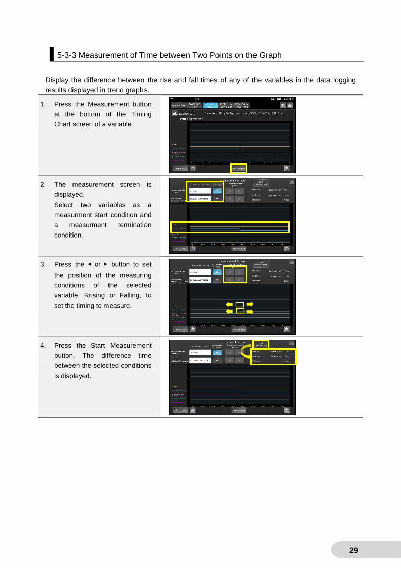
5-3-3 Measurement of Time between Two Points on the Graph
Display the difference between the rise and fall times of any of the variables in the data logging
results displayed in trend graphs.
1. Press the Measurement button
at the bottom of the Timing
Chart screen of a variable.
2. The measurement screen is
displayed.
Select two variables as a
measurment start condition and
a measurment termination
condition.
3. Press the ◀ or ▶ button to set
the position of the measuring
conditions of the selected
variable, Rrising or Falling, to
set the timing to measure.
4. Press the Start Measurement
button. The difference time
between the selected conditions
is displayed.

30
5-3-4 Screen Transition: Downloading Data Log Setting File
Initial state
Confirmation dialog
Completion dialog Dowonload error dialog
No Data Log Setting files
in the USB memory
Lack of necessary files

31
5-3-5 ScreenTransition: Graphic Display
Data log file selection screen
Display Variable selection screen
Timing Chart screen Measurement screen

32
5-4 Restore Safety Program at Site
The safety program of the safety CPU unit is changed with Sysmac Studio. Conventionally, the program restoring at site required Sysmac Studio. However, this demo screen enables the program to be downloaded from the USB memory of the NA.
5-4-1 Download Restore File
Transfer a restored file from NA’s USB memory to NX102/CSG unit’s memory card first.
1. Create a new folder, Restorefile,
under the Root directry in NA5’s
USB memory.
2. Save the Safety CPU Unit’s
restored file created with
Sysmac Studio to the folder.
Plug in the USB memory into
NA5.
3. Press Safety CPU Demo
Screen.
4. Click the Restored File
Download tab.
8. Login window appears. Enter the
followings:
Username omron
Password omron123
5. Press Login.

33
Precoutions for Correct Use
If you have logged in before downloading the restored file, the login screen does not appear. Click
the Restored File Download tab to go to Restore File Download screen.
Precoutions for Correct Use
Do not change the original filename, "SLSystem.dat".
6. Restored File Download screen
appears. Press the Download
button.
7. Confirmation dialog window is
displayed. Press OK.
8. Completion dialog window
appears. Press OK.

34
5-4-2 Restoring on Safety CPU Unit
The next procedure is implemented with the dip switches and LED displays on the front of the Safety CPU Unit.

35

36
5-4-3 Screen Transition: Safety Program Restoring
The following is the flow of restoring the safety program at site.
Initial state No restored files in NA’s USB memory
Confirmation dialog
Completion dialog
Download error dialog

37
6 Appendix: Specifications
6-1 Screen Overview
・Base Screens
Menu (Initial Screen) Safety CPU Demo Movie
Jump to other screens from this
screen.
Play demonstration movies.
I/O Table Safety I/O LED Monitor
Display I/O tables of the controller.
Indicate LED status of the Safety I/O.
Restored File Download Data Log Setting File Download
Download restored files of the Safety
CPU Unit to the controller.
Download data log setttings of the
Safety CPU Unit to the controller.

38
Data Log File Selection Data Log Display
Select the data log file to display.
Display the selected datalog file’s
timimg chart.
Safety Signature Confirmation
Display the information about safety
signature of the Safety CPU Unit.
・Pop-up Screens
Display Variable Selection Measurement
Select the variable to display from the
variables logged in the file selected on
the Data Log File Selection screen.
Display the difference between the two
variables which are displayed on Data
Log Display screen.
Login Logout
Execute login process.
Execute logout process.

39
Menu Screen
Safety CPU Demo
Movie
I/O Table
Login
Logout
Safety Signature
Confirmation
Data Log File
Selection
Restored File
Download
Data Log Setting
File Download
Safety I/O LED Monitor
Display Variable Selection
Data Log Display
Measurement
Safety CPU Demo Function Group
User login is required:
- to display Restored File Download Screen,
- to display Data Log Setting File Download Screen,
- to save the safety signature in the Safety Signature Confirmation Screen.
Log in on Login Screen beforehand or on the pop-up login screen displayed at screen transit.
The user name and password set for the demo project are as follows:
・User name omron
・Password omron123
6-2 Screen Transition and Security Level
ScreenTransition Diagram

40
6-3 Detail Screen Specifications
6-3-1 Menu Screen
This screen is displayed when Safety CPU demo unit startups.
You can jump to each functional screen from here.
・Configuration
No Part Description
1 Data Display Display the user name who logging in.
2 Data Display Show the logging in user’s authority.
3 Data Display Display the current time.
4 Button Jump to Safety CPU Demo Movie Screen.
5 Button Jump to Saefty CPU Demo Screen.
6 Button Jump to Login Screen.
7 Button Jump to Logout Screen.
8 Button Switch languages.
9 Button Hidden button.
Press and hold for 2 seconds to switch Chinese to Taiwanese.
Everytime you press and hold the button for 2 seconds, Chinese and
Taiwanese are alternated.
1
2
3
4
5
6 7
8
9

41
6-3-2 I/O Table Screen
On this screen, the I/O table of the selected controller is displayed.
・Configuration
No Part Descripiton
1 Data Display Display the user name who logging in. It’s due to NA’s security function.
2 Data Display Show the logging in user’s authority. It’s due to NA’s security function.
3 Data Display Display the current time.
4 Button Jump to each Saefty CPU Demo Screen.
5 Button Jump to the troubleshooter screen of the connected controller.
6 Button Jump to Menu Screen.
7 DropDown
Button
Select the controller to display its I/O table.
Press Select Device to display the I/O table of the selected controller.
8 Data Display Display the I/O table of the connected controller.
9 Data Display Jump to the Safety I/O LED Monitor Screen of the selected slot number.
10 Button Move the display range when 6 or more units are connected to the controller.
Precoutions for Correct Use
The I/O Monitor button is not displayed in the slot where a Safety I/O Unit is not installed.
You can jump to Safety I/O LED Monitor Screen only when a Safety I/O Unit is connected.
1 2 3
4
8
9
10
5
6 7

42
6-3-3 Safety I/O LED Monitor Screen
This screen displays the LED monitor of the unit selected in 5-3-2 I /O Table Screen.
This screen supports safety I/O units (NX SI Series and NX SO Series).
The LED status is updated at 2-second intervals. Manual update at any timing is also possible.
Press the Manual Update button (No10).
Note: It does not support the normal NX-I/O unit.
・Configuration
No Part Descripiton
1 Data Display Display the user name who logging in.
2 Data Display Show the logging in user’s authority.
3 Data Display Display the current time.
4 Button Jump to each Saefty CPU Demo Screen.
5 Button Jump to the troubleshooter screen of the connected controller.
6 Button Jump to Menu Screen.
7 Data Display Display the connecting controller’s name and IP address.
They are not to be changed on this screen.
8 Data Display Show the selected slot number and model
9 Data Display Display the LED status of Safety I/O Unit.
10 Button Update the displaying LED status manually.
11 Button Indicate the LED status of the unit on the left.
12 Button Indicate the LED status of the unit on the right.
13 Button Jump to I/O Table Screen.
1 2 3
4
8
10
11
5 6
7
9
12
13
43
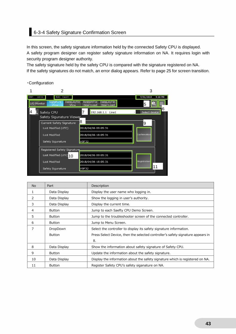
6-3-4 Safety Signature Confirmation Screen
In this screen, the safety signature information held by the connected Safety CPU is displayed.
A safety program designer can register safety signature information on NA. It requires login with
security program designer authority.
The safety signature held by the safety CPU is compared with the signature registered on NA.
If the safety signatures do not match, an error dialog appears. Refer to page 25 for screen transition.
・Configuration
No Part Description
1 Data Display Display the user name who logging in.
2 Data Display Show the logging in user’s authority.
3 Data Display Display the current time.
4 Button Jump to each Saefty CPU Demo Screen.
5 Button Jump to the troubleshooter screen of the connected controller.
6 Button Jump to Menu Screen.
7 DropDown
Button
Select the controller to display its safety signature information.
Press Select Device, then the selected controller’s safety signature appears in
8.
8 Data Display Show the information about safety signature of Safety CPU.
9 Button Update the information about the safety signature.
10 Data Display Display the information about the safety signature which is registered on NA.
11 Button Register Safety CPU’s safety siganature on NA.
1 2 3
4
8
10
5 6
7
9
11

44
6-3-5 Date Log File Selection Screen
A list of data logging result files saved in Safety CPU’s SD card is displayed. You can select a file
from this list.
Press the Select File button (No.10) after selecting the file and the screen will be changed to
Variable Selection Screen.
・Configuration
No Part Description
1 Data Display Display the user name who logging in.
2 Data Display Show the logging in user’s authority.
3 Data Display Display the current time.
4 Button Jump to each Saefty CPU Demo Screen.
5 Button Jump to the troubleshooter screen of the connected controller.
6 Button Jump to Menu Screen.
7 DropDown
Button
Select the controller to display its data log file.
Press the Select Device button to display a data log file list of the selected
controller in 9.
8 Button Update the data log file list displayed in 9.
9 ListBox Display a list of data log files stored in the SD card of the Safety CPU. A file is
selected in this box.
10 Button Open the file selected in 9 and move to Variable Selection Screen.
1 2 3
4
8
10
5 6
7
9

45
6-3-6 Display Variable Selection Screen
A list of variables that logged in the data log file selected in the previous section, 6-3-5 Data Log File
Selection Screen, is shown in this screen.
Select the variable to display on Data Log Display Screen.
You can choose up to 10 variables.
・Configuration
No Part Description
1 Check Button Display the variables that are logged in the data log file. Select any variables
here.
Up to 10 variables are displayed on one screen.
2 Button Available if 10 or more variables are logged.
Switch the variables to be displayed.
3 Button Deselect all variables.
4 Button Jump to Data Log Display Screen.
Not allowed to press it unless at least one file is selected.
5 Button Close this screen and move to Data Log File Selection Screen.
1
2
3
4
5

46
6-3-7 Data Log Display Screen
Data log of the valiable which selected in 6-3-6 Variable Selection Screen.
・Configuration
No Part Description
1 Data Display Display the user name who logging in.
2 Data Display Show the logging in user’s authority.
3 Data Display Display the current time.
4 Button Jump to each Saefty CPU Demo Screen.
5 Button Jump to the troubleshooter screen of the connected controller.
6 Button Jump to Menu Screen.
7 Data Display Show the selected data lof file name.
8 Data Display Display the selected variable.
9 BrokenLineGraph Indicate the data logging result of the selected variable.
10 Button Jump to Variable Selection Screen.
11 Button Left-scroll through a graph of the data logging result.
12 Button Right-scroll through a graph of the data logging result.
13 Button Jump to Measurement Screen.
1 2 3
4
9
10
5 6
7
8
11 12 13

47
6-3-8 Measurement Screen
The elapsed time for the two triggers of the variable that is displayed on Data Log Display Screen,
described in 6-3-7, is measured in this screen.
・Configuration
No Part Description
1 Drop Down Select a variable for the measurment start condition.
2 Drop Down Select a variable for the measurment termination condition.
3 Button Select a measurment condition for the measurment start condition: rising or
falling.
4 Button Select a measurment condition for the measurment termination condition:
rising or falling.
5 Button Search for a position that satisfies the trigger condition forward from the
position where the trigger is currently applied under the measurment start
condition.
6 Button Search the position where the trigger condition is satisfied forward from the
position where the trigger is currently applied under the measurment
termination condition.
7 Button Search the position that satisfies the trigger condition backward from the
position where the trigger is currently applied under the measurment start
condition.
8 Button Search the position that satisfies the trigger condition backward from the
position where the trigger is currently applied under the measurment
termination condition.
9 Button Start measuring.
10 Data Display Display the time when the trigger condition of the measurment start
condition is satisfied.
11 Data Display Display the time when the trigger condition of the measurment termination
condition is satisfied.
12 Data Display Display the difference between the measuring start time and end time.
13 Button Close this screen.
1 3
12
13
2 4
5
6
9
1
11
7
8
48
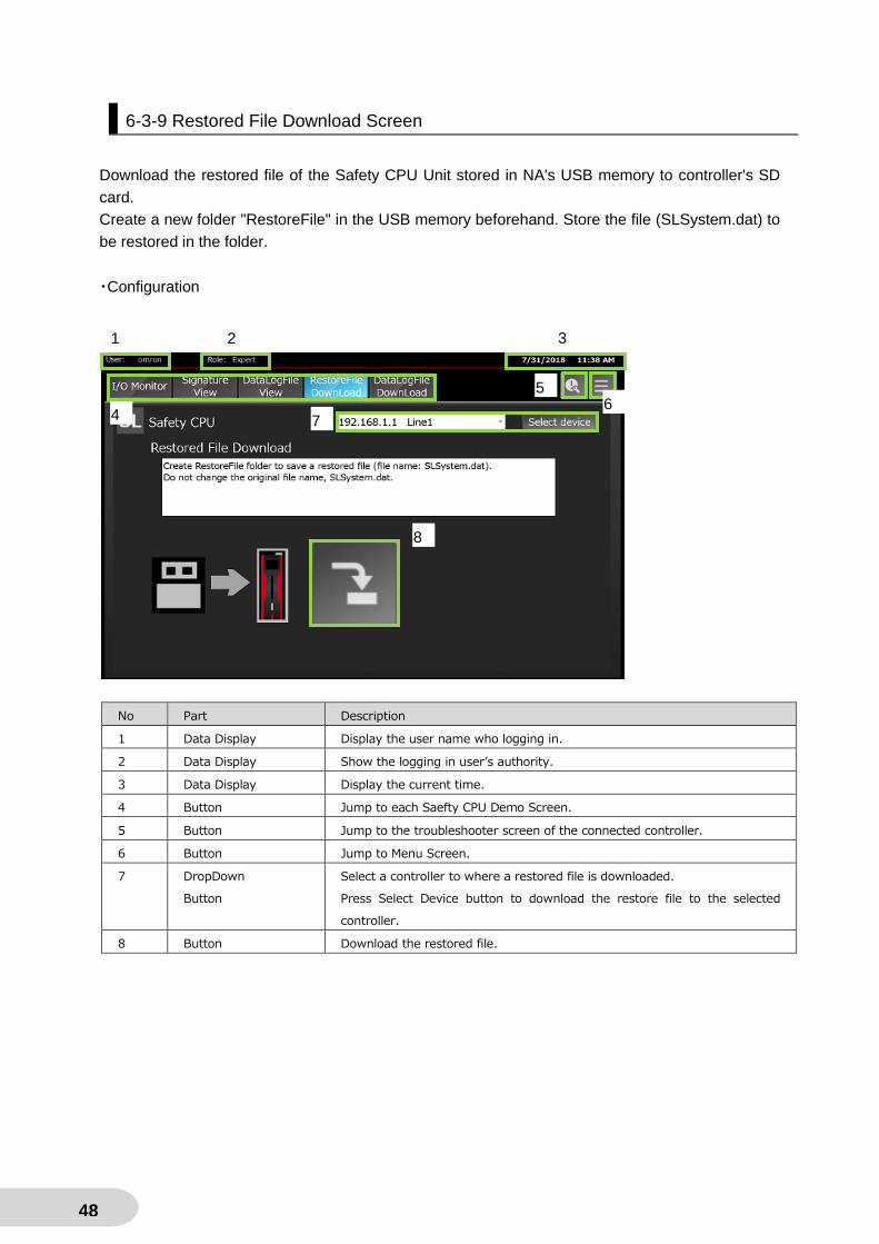
6-3-9 Restored File Download Screen
Download the restored file of the Safety CPU Unit stored in NA's USB memory to controller's SD
card.
Create a new folder "RestoreFile" in the USB memory beforehand. Store the file (SLSystem.dat) to
be restored in the folder.
・Configuration
No Part Description
1 Data Display Display the user name who logging in.
2 Data Display Show the logging in user’s authority.
3 Data Display Display the current time.
4 Button Jump to each Saefty CPU Demo Screen.
5 Button Jump to the troubleshooter screen of the connected controller.
6 Button Jump to Menu Screen.
7 DropDown
Button
Select a controller to where a restored file is downloaded.
Press Select Device button to download the restore file to the selected
controller.
8 Button Download the restored file.
1 2 3
4
5 6
7
8

49
6-3-10 Data Log Setting File Download Screen
Download a data log setting file stored in NA's USB memory to controller's SD card.
Create a new folder "DataLogSettingFile" in the USB memory beforehand. Store a safety logging
setting file (setting file name.dat) and a safety logging setting check file (setting file name.txt) in the
folder.
・Configuration
No Part Description
1 Data Display Display the user name who logging in.
2 Data Display Show the logging in user’s authority.
3 Data Display Display the current time.
4 Button Jump to each Saefty CPU Demo Screen.
5 Button Jump to the troubleshooter screen of the connected controller.
6 Button Jump to Menu Screen.
7 DropDown
Button
Select a controller to where a restore file is downloaded.
Press the Select Device button to download the restore file to the selected
controller.
8 Button Download the restore file.
9 ListBox Display to select a logging file list of logging setting No.1.
10 ListBox Display to select a logging file list of logging setting No.2.
11 Button Download the logging file selected in 9.
12 Button Download the logging file selected in 10.
1 2 3
4
5 6
7
8
9
10
11
12

50
6-3-11 Safety CPU Demo Movie Screen
Safety CPU demonstration movies are played on this screen. Both Japanese and English are
available.
Different movie may be played according to the language.
・Configuration
No Part Description
1 Data Display Display the user name who logging in.
2 Data Display Show the logging in user’s authority.
3 Data Display Display the current time.
4 Media Player Play the Safety CPU demo movie.
5 Button Jump to Menu Screen.
6 Button Stop the movie.
7 Button Start the movie.
8 Button Pause
1 2 3
4
6
5 7
7 8
51
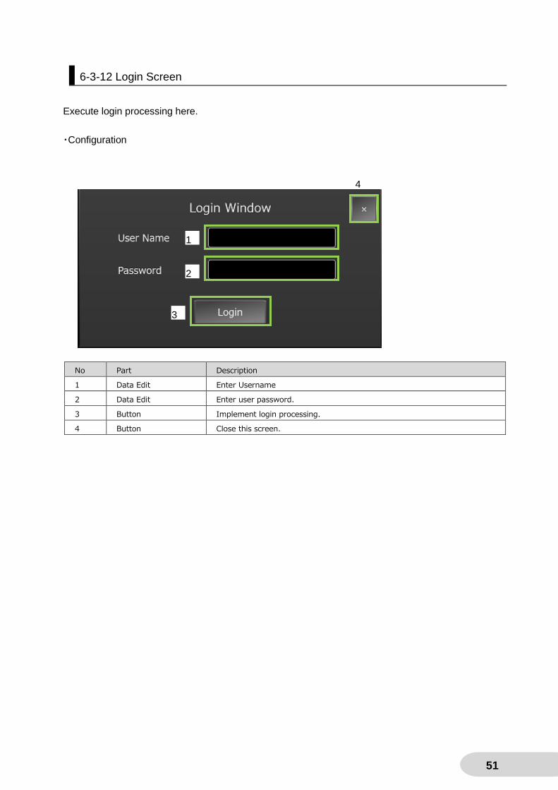
6-3-12 Login Screen
Execute login processing here.
・Configuration
No Part Description
1 Data Edit Enter Username
2 Data Edit Enter user password.
3 Button Implement login processing.
4 Button Close this screen.
1
4
2
3

52
6-3-13 Logout Screen
In this screen, a logout process is Impremented.
・Configuration
No Part Description
1 Button Implement logout processing.
2 Button Close this screen without logout processing.
3 Button Close this screen.
1
4
2
53
Revision History
Revision Code Date Revised Content
01 July 2018 Original production

2018
0718 (0718) V447-E1-01


![NA-series Programmable Terminal OMRON Standard IAG Library … · 2020. 3. 24. · OMRON Standard IAG Library . NA5-15[]101[] NA5-12[]101[] NA5-9[]001[] NA5-7[]001[] V415-E1-04 .](https://static.documents.pub/doc/80x56/60d29f4109fb9d432258db52/na-series-programmable-terminal-omron-standard-iag-library-2020-3-24-omron.jpg)


![Practices Guide Remote Solution - Omron · Programmable Terminal NB-series . Practices Guide . Remote Solution . NB3Q-TW0[]B NB5Q-TW0[]B](https://static.documents.pub/doc/80x56/6055a29317fdbf63635d2ca7/practices-guide-remote-solution-omron-programmable-terminal-nb-series-practices.jpg)


