Page 1
1
Programmed Wrapping and Assembly of Droplets with Mesoscale Polymers
Dylan M. Barber, Zhefei Yang, Lucas Prévost, Olivia du Roure, Anke Lindner, Todd Emrick,*
and Alfred J. Crosby*
D. M. Barber, Dr. Z. Yang, Prof. T. Emrick, Prof. A. J. Crosby
Polymer Science and Engineering Department
University of Massachusetts Amherst,
Amherst MA, 01003-9263, USA
L. Prévost, Prof. O. du Roure, Prof. A. Lindner
PMMH, ESPCI Paris, PSL Research University, CNRS
Université de Paris, Sorbonne Université,
Paris, 75005, France
Keywords: mesoscale, capillary assembly, bioinspired architectures, responsive materials,
photopatterning
Nature is remarkably adept at using interfaces to build structures, encapsulate reagents, and
regulate biological processes. Inspired by Nature, we describe flexible polymer-based ribbons,
termed “mesoscale polymers” (MSPs), to modulate interfacial interactions with liquid droplets.
This produces unprecedented hybrid assemblies in the forms of flagellum-like structures and
MSP-wrapped droplets. Successful preparation of these hybrid structures hinges on interfacial
interactions and tailored MSP compositions, such as MSPs with domains possessing distinctly
different affinity for fluid-fluid interfaces as well as mechanical properties. In situ
measurements of MSP-droplet interactions confirm that MSPs possess a negligible bending
stiffness, allowing interfacial energy to drive mesoscale assembly. By exploiting these
interfacial driving forces, mesoscale polymers are demonstrated as a powerful platform that
underpins the preparation of sophisticated hybrid structures in fluids.
1. Introduction
Nature provides striking examples of mesoscale assemblies featuring properties and
architectures that inspire synthetic replication. Some naturally occurring structures take the
form of long, fibrous building blocks that act in concert with spheroids, such as droplets,
colloidal particles, or live cells. For example, fiber-in-droplet packing is exemplified by
spooling observed in spider capture silk,[1-3] in which a fiber is periodically wetted with aqueous
droplets and winds into an internally spooled configuration. The balance between interfacial
energy and fiber bending energy drives such assembly, as well as the dissipative, damage-
preventing mechanisms activated upon impact-driven disassembly and re-assembly. Another
example is the integration of flagella and fimbriae with the membrane of bacteria. These long,
flexible mesostructures couple with the vesicle-like core to modulate interfacial interactions
with their surroundings.[4-11] These examples illustrate how assemblies of fibers and spheroids
Page 2
2
with well-controlled interactions and length scales give rise to advantageous properties and
performance. While some synthetic systems demonstrate isolated principles of such natural
phenomena,[12,13] a robust platform with material-, interfacial-, and geometry-enabled tuning of
fiber-spheroid assemblies has yet to be realized.
Figure 1a describes our use of polymer ribbons, termed mesoscale polymers (MSPs), at the
interface of oil-in-water droplets, in which three modes of interaction were identified: non-
adhesion, adhesion without wrapping, and spontaneous wrapping. These interactions are
dictated by the critical strain energy release rate, Gc = ow + pw - op (comprising the oil-water,
polymer-water, and oil-polymer interfacial tensions), and the critical elasto-adhesive length,
Rc=√Et3/Gc, a droplet radius defined by MSP mechanics (Young’s modulus E), interfacial
strength (Gc), and geometry (thickness t), above which an adhesive MSP spontaneously wraps
droplets.[12,13] A pH-responsive trigger embedded in the MSPs controls the observed assembly
mode. Figure 1b describes MSPs with segments of alternating compositions, termed mesoscale
block copolymers (MSBCPs), such that Gc and Rc are partitioned along the ribbon length. When
brought into contact with a droplet of radius R, selective wrapping is designed to afford droplets
with one or many pendent arms. In this paper, we realize the vision in Figure 1, starting from
monomer and copolymer synthesis, fabrication of MS(BC)Ps (thickness t ~ 100-600 nm, width
w ~ 10-35 m, and length 2-4 mm), and MS(BC)P contact with emulsion droplets (radius R =
6-350 m). Key structures were derived from different ribbon interactions with droplets,
including weak adhesion (Figure 1c, far left), spontaneous wrapping (Figure 1c, center left),
and selective wrapping by specific MSBCP segments to afford structures with one (Figure 1c
center right) or many (Figure 1c far right) arms extending into the surrounding fluid, or a
mesoscale micelle. By embedding responsive chemistry into MSPs, we modulate the resulting
ribbon/droplet architecture and in turn produce a new materials toolbox of hybrid structures.
Moreover, by providing access to a broad array of structures from mesoscale ribbons and
droplets, we build a platform of increasingly sophisticated soft materials that begin to emulate
the exquisite examples found in Nature.
Page 3
3
2. Materials preparation
The MSPs described in this work were prepared with reactive and functional polymers using
flow-coating methods we described previously.[14-16] The polymers were designed to exhibit pH
response (polymer 1) and amenability to photopatterning (polymer 2), as shown in Figure 2a.
Polymer 1 (Mn = 38 kDa, Đ = 2.7) was prepared by free radical copolymerization of
dimethylaminoethyl methacrylate (DMAEMA) with 5 mole percent of benzophenone
methacrylate (BPMA) and 1 mole percent of fluorescein-o-methacrylate (FMA). The tertiary
amines enable pH response by transitioning from charge neutral to cationic with increasing
acidity,[17-20] while BPMA imparts a crosslinking mechanism and FMA contributes
fluorescence to aid visualization. Copolymer 2 (Mn = 21 kDa, Đ = 2.2) was prepared by free
radical polymerization of t-butyl methacrylate (TBMA) with 2 mole percent of glycidyl
methacrylate (GMA), 4 mole percent of triphenylsulfonium 4-vinylbenzenesulfonate
(TPS4VBS), and 0.2 mole percent of rhodamine B methacrylate (RBMA). In polymer 2, the
aromatic sulfonium sulfonate comonomer functions as a photoacid generator upon UV
exposure to trigger acid-catalyzed deprotection of the t-butyl esters and crosslinking via the
glycidyl ethers, affording MSPs with segments of alternating composition, termed mesoscale
block copolymers (MSBCPs).[21]
Figure 1. System design. MS(BC)P-droplet interactions are dictated by controlling material properties (Gc, E)
and geometry (t, R) via pH and spatial partitioning: a) MSPs adopt non-adhesive (left), adhesive (center), and
wrapped (right) interaction modes, stemming from the pH-dependent work of adhesion (Gc) and the relative size
of the droplet radius R and critical elasto-adhesive length Rc; b) MSBCPs, with segments of alternating
composition, Gc, and R
c, enable selective wrapping for all droplet radii R
c2a < R < R
c2b, affording droplets with 1
(left) or many (right) arms; c) micrographs (left to right) of MSPs in adhesive (R < Rc1
) and wrapped (R > Rc1
)
modes, and MSBCPs in selectively wrapped (Rc2a
< R < Rc2b
) modes with 1 or many arms.
Page 4
4
To prepare the MSPs, a clean glass slide (24 mm x 40 mm x 170 m) was coated with a ~50
nm layer of poly(styrene sulfonate) (PSS, sodium salt) at 2 or 4 mm intervals to afford stripes
of bare glass ~100 m wide, over which was flow-coated a toluene solution of polymer 1 or 2
(Figure 2b left).[14-16] The substrate was translated in 1 mm intervals at 3 mm s-1, with a 1.1-1.5
s delay between steps to deposit the MSPs. The ribbons were then irradiated i) at = 365 nm
(3300 mJ cm-2) (copolymer 1) to afford a crosslinked PDMAEMA network (schematic Figure
2b, purple) or at ii) = 254 nm (200-695 mJ cm-2) through a photomask, then heated to 150 °C
for 60 s (copolymer 2), to afford MSBCPs with alternating segments of hydrophobic, glassy
PTBMA and hydrophilic, crosslinked poly(methacrylic acid) (PMAA, Figure 2b, red and blue,
Figure S1). The ribbons were cut into 2-4 mm long segments with a CO2 laser engraver ( =
10.6 m) and subjected to reactive ion etching with O2 plasma for 30 s to remove any residual
polymer film between the MSPs. The MSPs were released from the substrate by submerging
the sample in an aqueous solution to dissolve the underlying PSS layer, then brought into
contact with oil-in-water droplets; the resulting assemblies were studied as a function of their
interfacial activity (Gc) and critical elasto-adhesive length (Rc).
3. Controlling ribbon-droplet architectures with pH
Experiments with MSPs prepared from copolymer 1 were performed in pH 1-10 buffer
solutions using individual perfluorodecalin (PFD) droplets (R = 6-350 m) to avoid coalescence.
Pendent drop tensiometry revealed the oil-water surface tension ow to be roughly constant (~50
mN m-1) across this pH range. Droplet-to-MSP contact was achieved using a glass
microcapillary fixed to a hand-controlled micromanipulator (Figure 3a-b). Droplets were
introduced by inflation at the microcapillary tip or by emulsification and injection via pipette.
Fig. 2. Experimental design. a) Structure of PDMAEMA copolymer 1 and PTBMA copolymer 2 used to prepare
ribbons; b) copolymers were flow-coated onto a PSS-coated glass slide to afford ribbons of thickness t and width
w, with functionality determined by copolymer selection, then irradiated to afford MSPs or MSBCPs (structural
representations simplified for clarity).
Page 5
5
The optical micrograph in Figure 3b features an MSP adhered end-on to the surface of a PFD
droplet, alongside the microcapillary tip. The schematics in Figure 3c illustrate a typical
experimental setup. The microcapillary tube and translating stage are used to probe
MSP/droplet interactions by moving droplets through the fluid phase; pH-dependent assembly
spans weak adhesion, possibly mediated by non-uniformities on the MSP surface, to
spontaneous wrapping. We note that MSPs were observed to spontaneously curve into wavy
structures or well-defined helices, especially in aqueous environments from pH 1-6; the
observed curvature, a function of MSP mechanical properties and interfacial interactions with
the surrounding aqueous phase, was used to estimate a pH-independent copolymer modulus of
~200 MPa by helix extension in viscous flow (details in SI).[15,22,23]
3.1. Weak adhesion modes: ribbon stretching and flagellum-like assemblies
From pH 1-6, MSPs and droplets were observed to slide past one another upon contact, with
adhesion occurring randomly along the MSP. Figure 3d (left) shows sequential frames from
Video S1, in which a coiled MSP (helix radius = 38 m) is suspended between the substrate
and an adhered droplet (R = 132 m). By translating the substrate, the helix transitions from
unstretched (top) to extended (center), to fully detached from the droplet (bottom), recoiling
like a stretched spring. This adhesion is too weak to macroscopically deform the droplet before
detachment. Video S2 illustrates similar adhesion at pH 4, while Video S3 displays an example
of interfacial slip along a smooth MSP helix at pH 6. At pH 8, the adhesion occurred at the
MSP ends (Figure 3c,d center) to afford flagellum-like structures. Video S4 shows a droplet
attached to an MSP segment (length ~400 m) that is pushed through the fluid with the capillary
tip to demonstrate i) adhesion between the droplet and MSP end and ii) a lack of adhesion along
the MSP face. This flagellum-like assembly was maintained while the MSP was stretched
(Figure 3d center; Video S4), but when the droplet was brought into contact with the MSP face
(time T ~ 0.4-0.8 s) the two faces slid past one another without adhering. We speculate that
these distinct adhesion modes may result from laser cutting (CO2 laser, = 10.6 m) of the
MSPs after flow-coating, which heats the material[24] and potentially alters its surface
composition (i.e., via oxidation), Gc, and roughness.[25,26] We note that MSPs that were stored
under ambient conditions for ~3 weeks before release into pH 8 buffer qualitatively exhibited
a decrease in selectivity for adhesion at the end.
Page 6
6
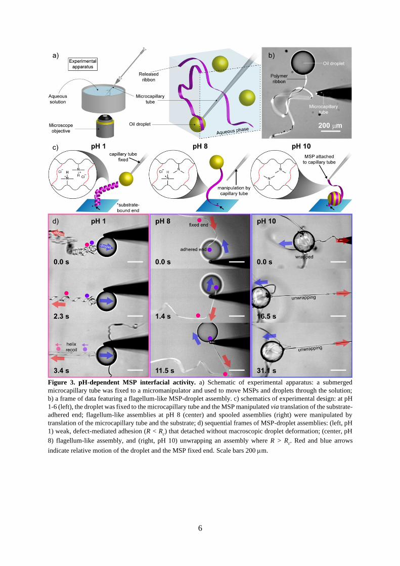
Figure 3. pH-dependent MSP interfacial activity. a) Schematic of experimental apparatus: a submerged
microcapillary tube was fixed to a micromanipulator and used to move MSPs and droplets through the solution;
b) a frame of data featuring a flagellum-like MSP-droplet assembly. c) schematics of experimental design: at pH
1-6 (left), the droplet was fixed to the microcapillary tube and the MSP manipulated via translation of the substrate-
adhered end; flagellum-like assemblies at pH 8 (center) and spooled assemblies (right) were manipulated by
translation of the microcapillary tube and the substrate; d) sequential frames of MSP-droplet assemblies: (left, pH
1) weak, defect-mediated adhesion (R < Rc) that detached without macroscopic droplet deformation; (center, pH
8) flagellum-like assembly, and (right, pH 10) unwrapping an assembly where R > Rc. Red and blue arrows
indicate relative motion of the droplet and the MSP fixed end. Scale bars 200 m.
Page 7
7
3.2. Capillary wrapping
At pH 10, the MSPs were observed to spontaneously wrap the droplets upon contact between
the ribbon face and fluid-fluid interface, suggesting both large Gc and R > Rc. This wrapping
event is in stark contrast to the weak adhesion observed at lower pH and marks a transition from
polycation (in acidic solution) to neutral polymer (in basic solution, Figure 3c inset
structures),[17-20] while a pH-independent E and ow implicate the polymer surface chemistry as
the driving force. Wrapping continued until terminated by one of several mechanisms,
including: i) onset of tension in the MSP, supplied by MSP adhesion to the substrate or
microcapillary tip; ii) wrapping over an existing coil rather than available oil-water interface;
or iii) consumption of the entire MSP length, to afford droplets with partial interfacial coverage.
The wrapped droplets were subsequently unwrapped by withdrawing the MSP via the
microcapillary tube (Video S5). Figure 3c (right) schematically depicts the experimental design,
while Figure 3d (right) displays frames from Video S5 that show clean unwinding of millimeters
of an MSP while it maintains its structural integrity. The unwound MSPs then wrap the droplets
again when tension is released and the wrapping/unwrapping cycles were repeated up to three
times, without noticeable change, for a given MSP-droplet pair. Video S6 and S7 demonstrate
cases of partial rewrapping to create assemblies in which droplets are decorated with arms that
extend into the continuous phase. Because wrapping stops when the MSP wraps upon itself, we
infer that it is confined to the oil-water interface, and further, that the wrapping mechanism
requires an uninterrupted 3-phase contact line at the wrapping edge.
From a mechanics standpoint, the MSP-wrapped droplets can be described by a thin, wide
elastic beam confined to a curved oil-water interface.[12] The components of a wrapped
assembly of contact length Lc include bending (Ub = EIyyLc/2R2) and adhesion (U = GcwLc)
energies, where E is the elastic modulus, Iyy is the second moment of inertia for axial wrapping,
and Gc is critical strain energy release rate. When R = Rc, the wrapped and unwrapped states
are energetically equivalent, affording Rc = √EIyy
2Gcw ~ √
Et3
Gc. Thus, for R < Rc we expect adhesion
without wrapping, while for R > Rc we expect spontaneous wrapping. This relationship was
studied as a function of droplet radius R in the experiments shown in Figure 4. In Figure 4a
(and Video S8), the microcapillary tip was positioned adjacent to an MSP and used to introduce
a droplet, which grew until it contacted the MSP. Figure 4a (left) shows the system at T = 0.4
s, immediately before contact and wrapping. To the left, the MSP is fixed to the glass substrate,
and to the right, it is unconstrained and free to wrap the droplet. At T = 11 seconds (Figure 4a,
center), wrapping had nearly advanced one turn around the droplet, and the two wrapping edges
passed by one another at T = 1.4 s. Approximating wrapping at the droplet circumference, each
wrapping edge advanced at ~350 m s-1. After T = 1.6 s, the free MSP end was completely
wrapped, while the slack between the droplet and the fixed end was pulled tight at T = 7.6 s
(Figure 4a (right) and final frames of Video S8).
Page 8
8
To examine the impact of droplet size on wrapping, a ribbon-wrapped droplet with radius R =
279 m was pierced with the microcapillary tip and oil was continuously withdrawn to reduce
the droplet radius (Figure 4b). At R = 136 m, deflation stopped as applied force from the tip
translated the droplet without piercing
the surface. Despite the decrease in
droplet dimensions, the droplet
remained wrapped, with an appearance
of more substantial interfacial coverage.
Even in the presence of small droplets (R
~ 6-30 m) prepared by emulsification
via pipette, wrapping occurred such that
MSPs effectively connected multiple
droplets in series. For example, Figure
4c shows brightfield (left) and
fluorescence (right) micrographs of an
MSP (w = 14 m) wrapped around 13
droplets as small as R = 6 m (droplet
7). For even smaller droplets, where R <
w, we anticipate edgewise wrapping
dictated by a lateral moment of inertia Ixx, which becomes infinitesimally small as MSP
thickness tapers toward the edges (Figure S2). Accordingly, we expect wrapping even in cases
where the thickness t of the MSP central axis might otherwise prohibit lengthwise wrapping.
3.3. Evaluating MSP-droplet interactions
The energy landscape of elasto-adhesive MSP wrapping, as described by Gc, in pH 10 buffer
was probed by measuring the peel force, Fc, required to separate a wrapped MSP from the
droplet surface. As described in Figure 5, these measurements utilized deflection of a single
carbon fiber fixed to the end of a glass capillary tube that was dipped into a cyanoacrylate glue
and cured to afford a cantilever with a hydrophobic, adhesive bead near the tip. A sample of
MSPs was released into the buffer and PFD droplets were introduced by pipette. The cantilever
was brought into contact with a PFD droplet via a micromanipulator, which adhered to the cured
poly(cyanoacrylate) bead, then the cantilever-bound droplet was brought into contact with an
MSP to initiate spontaneous wrapping (Figure 5a). For ribbons with one end fixed to the
substrate, the MSP-droplet assembly was loaded by substrate translation, enabling direct
quantification of the applied force by measuring cantilever deflection. The applied force
increased linearly as the MSP stretched and the droplet deformed, as shown by the 3-phase
contact line meniscus (Figure 5b), until unwrapping began at a critical force, Fc. Fig 5c-d and
Figure 4. Critical elastoadhesive dimension Rc1. a) time
points of a droplet inflated until (left) ribbon contact, (center)
mid-wrap, and (right) pulled tight against the substrate-adhered
end; b) deflating a pre-wrapped droplet to R = 136 m without
any unwrapping; c) bright-field (left) and fluorescence (right)
micrographs showing complete wrapping of droplets with
diameter ≤ w = 14 m.
Page 9
9
Video S9 follow the progress of an experiment with droplet radius R = 88 m through two
complete loading cycles, with an unloading step in between the cycles. Force (Fig 5c, left) and
the applied energy release rate G (right, describing the energetics of separating the interface)
are plotted as a function ribbon length (LR) between its fixed end and the droplet contact point;
on the second cycle, the MSP was unwrapped until detachment, when the ribbon contact length
was exhausted. The loading curve exhibited two distinct regimes: linear loading, in which the
force increased monotonically with the droplet-to-fixed-end MSP length (LR), followed by a
plateau of sustained peel at constant force (Fc, blue data points) of 2.6 N;
the initial loading slope was consistent from cycle to cycle, as was Fc. During unloading, the
linear force-LR curve matched the slope of the loading curve, suggesting elastic recovery in the
stretched MSP. At F = 0, ~50 m of visible slack spontaneously rewrapped the droplet.
The second load cycle followed a similar stretch-plateau shape and loading continued until the
MSP detached completely from the fluid-fluid interface and dispersed in water. Figure 5d
corresponds to red data points in Figure 5c during the second loading cycle, with wrapped
lengths of ~140 m (i), ~85 m (ii), and ~0 m (end-adhered, iii), marking continuous
unwrapping before detachment (iv). The critical force for unwrapping is divided by w (~22 m,
measured from video frames) to define a critical energy release rate, Gc = 116 mN m-1 for the
Figure 5. Measuring MSP peel force and Gc by cantilever deflection. a) Schematic of experimental apparatus:
a droplet is adhered to the tip of a carbon fiber cantilever and partially wrapped by an MSP of suspended length
LR. The assembly is loaded by substrate translation to deflect the cantilever by distance ; b) false color
micrographs of the system at low load (left, no MSP-droplet meniscus) and while peeling (right, meniscus
formation); c) force-LR plot of a typical experiment, in which the sample is cycled through two load-peel events,
then peeled until rupture. Blue data points denote a visible meniscus and correspond to Fc and Gc; cycle averages
were combined to estimate peel force and Gc (dashed reference line with 95% confidence in gray); red points i-iv)
correspond to frames d) i-iv); d) sequential frames from the same peel experiment. The MSP unwraps (i, ii) from
the droplet surface until only the end adheres (iii), then is released from the interface (iv). False coloration
highlights the MSP. Scale bars b) 50 m and d) 100 m.
Page 10
10
copolymer 1-PFD interface in this solution (Figure 5c, reference line). For an MSP of thickness
t = 300 nm and modulus 200 MPa, the critical elasto-adhesive dimension for axial wrapping
(bending in Iyy) Rc ~7 m. We note that Rc is readily decreased by reducing t, which is
accomplished easily during ribbon fabrication by flow-coating.[14-16]
4. Building droplets with arms by photopatterning ribbons
Photopatterned ribbons prepared from copolymer 2 were used to study additional MSP-droplet
assembly modes. Here, composition, geometry, and interfacial chemistry are partitioned to
afford MSBCPs, reflecting spatial control of Rc such that only pre-determined segments wrap
the droplets. Remarkably, only the hydrophobic segments (composed of PTBMA) were
observed to wrap PFD droplets, while the hydrophilic PMAA segments exhibited no wrapping
tendency, suggesting that for droplet radii R ~ 60-150 m, Rc,PTBMA < R < Rc,PMAA.
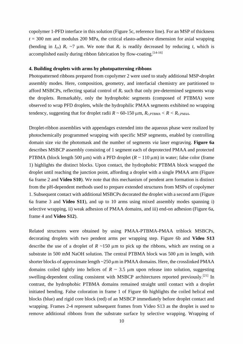
Droplet-ribbon assemblies with appendages extended into the aqueous phase were realized by
photochemically programmed wrapping with specific MSP segments, enabled by controlling
domain size via the photomask and the number of segments via laser engraving. Figure 6a
describes MSBCP assembly consisting of 1 segment each of deprotected PMAA and protected
PTBMA (block length 500 m) with a PFD droplet (R ~ 110 m) in water; false color (frame
1) highlights the distinct blocks. Upon contact, the hydrophobic PTBMA block wrapped the
droplet until reaching the junction point, affording a droplet with a single PMAA arm (Figure
6a frame 2 and Video S10). We note that this mechanism of pendent arm formation is distinct
from the pH-dependent methods used to prepare extended structures from MSPs of copolymer
1. Subsequent contact with additional MSBCPs decorated the droplet with a second arm (Figure
6a frame 3 and Video S11), and up to 10 arms using mixed assembly modes spanning i)
selective wrapping, ii) weak adhesion of PMAA domains, and iii) end-on adhesion (Figure 6a,
frame 4 and Video S12).
Related structures were obtained by using PMAA-PTBMA-PMAA triblock MSBCPs,
decorating droplets with two pendent arms per wrapping step. Figure 6b and Video S13
describe the use of a droplet of R ~150 m to pick up the ribbons, which are resting on a
substrate in 500 mM NaOH solution. The central PTBMA block was 500 m in length, with
shorter blocks of approximate length ~250 m in PMAA domains. Here, the crosslinked PMAA
domains coiled tightly into helices of R ~ 3.5 m upon release into solution, suggesting
swelling-dependent coiling consistent with MSBCP architectures reported previously.[21] In
contrast, the hydrophobic PTBMA domains remained straight until contact with a droplet
initiated bending. False coloration in frame 1 of Figure 6b highlights the coiled helical end
blocks (blue) and rigid core block (red) of an MSBCP immediately before droplet contact and
wrapping. Frames 2-4 represent subsequent frames from Video S13 as the droplet is used to
remove additional ribbons from the substrate surface by selective wrapping. Wrapping of
Page 11
11
additional MSBCPs advances until overlap with those present already. Notably, this does not
stop the wrapping events as observed for longer, substrate-adhered PDMAEMA MSPs at pH
10; rather, wrapping was seen to continue by pushing the previously wrapped segments across
the interface (T ~7.2-14.0 s).
4.1. Quantifying MSBCP segment-droplet interactions
The peel force of PTBMA segments at the PFD-water interface was measured by cantilever
deflection. MSBCPs of alternating 50 m blocks were prepared with one end fixed to the
substrate surface, released into pH 10 buffer solution, then brought into contact with a
cantilever-bound droplet (R ~ 60 m). Measurements were made by translating the substrate
with the adhered MSBCP end, pulling on the droplet, and measuring the deflection of the
attached cantilever. The system was taken through two complete load-unload cycles, then
loaded until detaching completely from the droplet surface (Video S14). Figure 6c represents
successive frames from the first cycle in this experiment, including: (i) an unstretched MSBCP;
(ii) loading until slack is removed; (iii) hydrogel segment stretching and droplet deformation;
and (iv) peeling (false coloration highlights the hydrophobic (red) and hydrogel (blue) domains).
The measured force is shown in Figure 6d, revealing continued loading, without peeling, until
a critical load of ~ 1460 nN is reached, when the system transitions to a partially peeled state.
For each cycle, the average peel force Fc is taken from blue data points, with a typical value of
~1100 nN. Four data points are highlighted as red triangles, corresponding to Figure 6c.i-iv,
revealing the load at each stage of the measurement. Relatively little force (~60 nN, ii) is
required to straighten the initially curved (i) PMAA domains, which stretch from ~115 m (low
load, ii) to ~160 m (1470 nN, iii, immediately before and 990 nN, iv, immediately after peel),
then elastically recover during unloading, consistent with expectations for a crosslinked
hydrogel. Notably, this strain concentration within hydrophilic PMAA gel domains enabled
direct measurement of gel modulus EPMAA ~ 2 MPa by tracking the segmental junction points
between PMAA and PTBMA domains. By contrast, we estimated EPTBMA on the order of 1 GPa
based on the known Tg,PTBMA of 116-118 °C,[27,28] a 500-fold modulus difference achieved simply
by photopattern-mediated swelling.
Page 12
12
.
The measured peel force (Fc) represents the energy per unit length required to unwrap ribbons
from the curved oil-water interface. Having demonstrated that capillary interactions dominate
bending stiffness at the selected length scales in PDMAEMA MSPs of modulus 200 MPa (Gc
= 116 mN m-1, Rc = 7 m for t = 300 nm), we applied the same assumption when measuring
MSBCP segments. Dividing Fc by segment width w = 12 m (measured via optical profilometry
before release), Gc ~ 93 mN m-1 (Figure 6d reference line) was calculated. Thus, for a
hydrophobic MSBCP segment with t = 300 nm, Rc = 17 m, while smaller values are readily
accessible by printing thinner MSBCPs. Notably, Gc for MSPs (~116 mN m-1) and hydrophobic
MSBCP segments (~93 mN m-1) are comparable to the oil-water interfacial tension ow = 51
mN m-1 measured by pendent drop tensiometry; moreover, MSBCP adhesion at the oil-water
interface ceased upon the addition of a polymer surfactant, further connecting the high energy
oil-water and polymer-water interfaces to adhesion and wrapping phenomena. Together, our
measurements of Gc and ow combined with loss of adhesion in the presence of surfactant
implicate the oil-water and polymer-water interfaces as a primary driving force for large scale
Figure 6. Droplet-MSBCP assemblies. Assembly of droplets with a) “diblock” MSP in RO water and b)
“triblock” MSP in 500 mM NaOH: a) the droplet and ribbon (false color, top, red = hydrophobic; blue =
hydrophilic) are brought into contact; selective wrapping affords a droplet with an arm (2nd frame); subsequent
ribbon addition allows installation of 2 (3rd frame) or many (4th frame) arms; b) assembly of MSBCPs (false color,
top) enables shorter arms driven to coil in basic solution; c) cantilever deflection of an MSBCP with 1 wrapped
segment to quantify peel force; d) plot of measured force F (left axis) and G (right axis) as a function of peel length
of an adhered MSBCP subjected to 3 load-peel cycles. Red data points correspond to frames c.i-iv); blue data
points denote peeling (Fc, Gc); cycle averages were combined to calculate peel force and Gc (dashed reference line
with 95% confidence in gray). Scale bars a-b) 200 m and c) 100 m.
Page 13
13
assembly of mesoscale ribbons. Notably, despite a modulus approximately 3 orders of
magnitude smaller than the glassy PTBMA domains, the PMAA gel segments adhered to
droplets without wrapping, suggesting an equally dramatic change in Gc from segment to
segment. Thus, MSBCPs possess partitioned domains of alternating physical and mechanical
properties, including a 500-fold difference in elastic modulus, and dramatic differences in Gc
and Rc that enable selective wrapping and assembly upon contact with oil-in-water droplets.
5. Conclusion
In summary, we described the use of compliant, surface-active, mesoscale polymer ribbons to
build assemblies with liquid droplets via the fluid-fluid interface of the droplets. We adapted a
model of cylindrical filaments at droplet surfaces to describe the uniquely flat geometry of
MSPs in contact with an oil-in-water droplet, spanning wrapping and non-wrapping interaction
modes as a function of a modulus-, geometry-, and Gc-dependent elasto-adhesive dimension Rc.
Using photocrosslinked MSPs derived from copolymer 1, we mapped pH-dependent
interactions, ranging from i) weak adhesion (Rc > R) from pH 1-8, including flagellum-like
architectures formed by selective adhesion at the MSP tip, to ii) spontaneous wrapping at pH
10, producing spools amenable to unwrapping, re-wrapping, and addition of pendent arms. We
employed the “built-in” photoacid generators in copolymer 2 to effect chemically amplified
deprotection and crosslinking, using a photomask to partition distinct properties into segments
along the ribbon length. Within the resulting MSBCP structures, hydrophobic PTBMA
segments were observed to selectively wrap oil-in-water droplets independent of pH, enabling
the construction of droplets with 1, 2, or many arms extended into solution. Moreover,
quantification of Gc and thickness-dependent Rc confirms that the bending compliance and
strong interfacial activity of MSPs and MSBCPs affords elasto-adhesive lengths of microns or
smaller. Together, these pH-, light-, and spatially-programmable structures provide a robust
platform to transform simple soft materials building blocks and interaction modes into
sophisticated meso-to-macroscale bio-inspired assemblies.
Supporting Information
Supporting Information is available from the Wiley Online Library or from the author.
Acknowledgements
This project was supported by the Department of Energy, Office of Basic Energy Sciences,
Division of Materials Science and Engineering under award number DE-SC0008876 and a
National Defense Science and Engineering Graduate (NDSEG) Fellowship awarded to
D.M.B. A.L., L.P. and D.M.B. acknowledge funding from the ERC Consolidator Grant
PaDyFlow (Grant Agreement no. 682367).
Page 14
14
References
[1] F. Vollrath, D. T. Edmonds, Nature 1989, 340, 305.
[2] H. Elettro, S. Neukirch, A. Antkowiak, F. Vollrath, Sci. Nat. 2015, 102, 41.
[3] H. Elettro, S. Neukirch, F. Vollrath, A. Antkowiak, Proc. Natl. Acad. Sci. 2016, 113,
6143.
[4] S. M. King, W. S. Sale, Mol. Biol. Cell 2018, 29, 698.
[5] G. L. Takei, M. Fujinoki, K. Yoshida, S. Ishijima, Mol. Hum. Reprod. 2017, 23, 817.
[6] D. M. Woolley, G. G. Vernon, J. Exp. Biol. 2001, 204, 1333.
[7] T. C. Adhyapak, H. Stark, Soft Matter 2016, 12, 5621.
[8] M. Jabbarzadeh, H. C. Fu, Phys. Rev. E 2018, 97, 012402.
[9] T. Rehman, L. Yin, M. B. Latif, J. Chen, K. Wang, Y. Geng, X. Huang, M. Abaidullah,
H. Guo, P. Ouyang, Microb. Pathog. 2019, 137, 103748.
[10] V. M. Suchanek, M. Esteban-López, R. Colin, O. Besharova, K. Fritz, V. Sourjik, Mol.
Microbiol. 2019, 1.
[11] P. Horváth, T. Kato, T. Miyata, K. Namba, Biomolecules 2019, 9, 462.
[12] R. D. Schulman, A. Porat, K. Charlesworth, A. Fortais, T. Salez, E. Raphaël, K.
Dalnoki-Veress, Soft Matter 2017, 13, 720.
[13] B. Roman, J. Bico, J. Phys. Condens. Matter 2010, 22, 493101.
[14] H. S. Kim, C. H. Lee, P. K. Sudeep, T. Emrick, A. J. Crosby, Adv. Mater. 2010, 22,
4600.
[15] J. T. Pham, J. Lawrence, D. Y. Lee, G. M. Grason, T. Emrick, A. J. Crosby, Adv.
Mater. 2013, 25, 6703.
[16] D. Y. Lee, J. T. Pham, J. Lawrence, C. H. Lee, C. Parkos, T. Emrick, A. J. Crosby,
Adv. Mater. 2013, 25, 1248.
[17] C.-A. Ghiorghita, F. Bucatariu, E. S. Dragan, Int. J. Biol. Macromol. 2018, 107, 1584.
[18] P. Van De Wetering, E. E. Moret, N. M. E. Schuurmans-Nieuwenbroek, M. J. Van
Steenbergen, W. E. Hennink, Bioconjug. Chem. 1999, 10, 589.
[19] Z. Guo, X. Chen, J. Xin, D. Wu, J. Li, C. Xu, Macromolecules 2010, 43, 9087.
[20] S. B. Abbott, W. M. de Vos, L. L. E. Mears, M. Skoda, R. Dalgliesh, S. Edmondson, R.
M. Richardson, S. W. Prescott, Macromolecules 2016, 49, 4349.
[21] D. M. Barber, A. J. Crosby, T. Emrick, Adv. Mater. 2018, 30, 1706118.
[22] J. T. Pham, J. Lawrence, G. M. Grason, T. Emrick, A. J. Crosby, Phys. Chem. Chem.
Phys. 2014, 16, 10261.
[23] J. T. Pham, A. Morozov, A. J. Crosby, A. Lindner, O. du Roure, Phys. Rev. E 2015, 92,
011004.
[24] D. Fried, S. F. Borzillary, S. M. McCormack, R. E. Glena, J. D. B. Featherstone, W. D.
Seka, Proc. SPIE 1994, 2128, 319.
[25] D. G. Waugh, J. Lawrence, C. D. Walton, R. B. Zakaria, Opt. Laser Technol. 2010, 42,
347.
Page 15
15
[26] S. Prakash, S. Kumar, Precis. Eng. 2017, 49, 220.
[27] J. M. Yu, P. Dubois, R. Jérôme, Macromolecules 1996, 29, 8362.
[28] S. Watanabe, T. Ohmura, K. Ueno, M. Murata, Y. Masuda, Polym. J. 2008, 40, 743.
Page 16
16
Supporting Information
Programmed Wrapping and Assembly of Droplets with Mesoscale Polymers
Dylan M. Barber, Zhefei Yang, Lucas Prévost, Olivia du Roure, Anke Lindner, Todd Emrick,*
and Alfred J. Crosby*
Methods
Chemicals. Methacryloyl chloride, rhodamine B, 4-dimethylaminopyridine (DMAP), N,N’-
dicyclohexylcarbodiimide (DCC), 2-hydroxyethyl methacrylate (HEMA), triphenylsulfonium
chloride (TPSCl), fluorescein-O-methacrylate (FOMA), toluene, perfluorodecalin (PFD),
buffer solutions, basic alumina, lithium chloride (LiCl), poly(sodium 4-styrenesulfonate) (PSS,
MW 70 kDa, Aldrich), 4-hydroxybenzophenone (4HBP, TCI America), methanol (MeOH),
dimethylformamide (DMF), hexanes, isopropanol (IPA, Fisher Scientific), sodium 4-
vinylbenzenesulfonate (Na4VBS, Alfa Aesar), and silica gel (Sorbent Technologies) were used
as received without further purification. Triethylamine (TEA, Aldrich) and dichloromethane
(DCM, Fisher Scientific) were dried over calcium hydride and distilled. 2.1% aqueous
ammonium hydroxide solution was prepared by diluting 28 wt% ammonium hydroxide solution
(Aldrich) into stirring RO water. 100 mM HCl solution was prepared by dropwise addition of
12.1 N HCl (Fisher Scientific) to a beaker of stirring RO water. 2-(Dimethylamino)ethyl
methacrylate (DMAEMA), tert-butyl methacrylate (TBMA), and glycidyl methacrylate (GMA,
Aldrich) were purified by passage through a plug of basic alumina. 2,2’-Azobisisobutyronitrile
(AIBN, Aldrich) was recrystallized from MeOH. Tetrahydrofuran (THF, Fisher Scientific) was
dried over sodium benzophenone ketyl, then distilled. N2 gas was dried by passing through
Drierite (W.A. Hammond Drierite Company).
Instrumentation. 1H NMR (500 MHz) spectroscopic data was collected using a Bruker Ascend
TM500 spectrometer with a Prodigy cryoprobe. Copolymer molecular weight was estimated
against PMMA standards by gel permeation chromatography (GPC), eluting in a mobile phase
of 0.01 M LiCl in DMF at 1 mL min-1 flow rate (Agilent 1260 Infinity isocratic pump) through
a 50 × 7.5 mm PL gel mixed guard column, a 300 × 7.5 mm PL gel 5 μm mixed C column, and
a 300 × 7.5 mm PL gel 5 μm mixed D column at 50 °C. Solute was detected using an Agilent
1260 Infinity refractive index detector. UV-ozone (UVO) surface treatment was conducted with
a Jelight Company, Inc. Model 342 UVO-Cleaner®. Laser engraving was carried out using a
Universal Laser Systems VLS3.50 laser engraver equipped with a 30W CO2 (10.6 m) laser
with 0.005“ z-axis offset, 2% power, 40% speed, and 1000 ppi pulse rate. Flow-coating was
carried out using a SmarAct, Inc SLC-1780s linear actuator. 365 nm UV-irradiation was
performed on a Newport 97435 lamp housing with a Newport 69910 power supply and Newport
6285 Mercury arc lamp or a Suss Micro Tec MA6 Mask Aligner. An OAI Instruments 1000
Watt DUV Exposure System equipped with a DUV 1000 lamp (Advanced Radiation
Page 17
17
Corporation) was used for all 254 nm UV irradiation. Reactive Ion Etch (RIE) experiments
employed an Advanced Vacuum Vision 320 MkII Reactive Ion Etch System with 50 sccm
O2(g) flow rate, 50 mTorr chamber pressure, 100 W RF power, and 13.56 MHz RF frequency.
Microscopy was conducted on an Axio Observer 7 Materials microscope equipped with a
Hamamatsu C11440 Orca-Flash4.0 Digital Camera, 2 Eppendorf TransferMan 4r
micromanipulators, an X-Cite 120LED (Excelitas Technologies), and Zeiss filter set 38 HE
(green fluorescence, copolymer 1) or 45 (red fluorescence, copolymer 2). Fourier-transform
Infrared (FT-IR) data were collected in attenuated total reflectance mode using a PerkinElmer
Spectrum One FT-IR Spectrometer equipped with a Universal ATR Sampling Accessory.
Optical profilometry data was collected using a Zygo NewView 7300 Optical Surface Profiler
(Amherst) or a Veeko Instruments Wyko NT9100 (Paris). Microcapillary tubes were prepared
by drawing glass capillary tubes (ChemGlass, 1.0-1.1 mm O.D.) in a P-1000 Flaming/BrownTM
Micropipette Puller System (Sutter Instrument) and the melted ends were opened using an MF-
830 Microforge (Narishige International).
Synthesis of benzophenone methacrylate (BPMA) monomer. BPMA synthesis was adapted from
a reported procedure.[1] In brief, a 500 mL round-bottom flask with a stir bar was flame-dried
and purged with dry nitrogen, then 4-hydroxybenzophenone (5.1 g, 25.7 mmol, 1 equivalent)
was added against a positive flow of dry N2(g). The flask was sealed with a septum. Dry TEA
(8 mL, 57.4 mmol, 2 equivalents) and dry DCM (75 mL) were added by syringe against positive
N2(g) pressure; the solution was stirred until homogeneous then cooled to 0 °C. Methacryloyl
chloride (4.8 mL, 49.6 mmol, 1.93 equivalents) in dry DCM (25 mL) was added dropwise while
stirring. The solution was allowed to return to 20 °C where it was stirred for 15.5 h, then
concentrated under vacuum, redissolved in ether, and washed with 2.1% aqueous ammonium
hydroxide solution. The product was purified by column chromatography (basic alumina as
stationary phase, 90:10 hexanes:ethyl acetate as eluent) to afford the desired product as white
crystals (4.0 g, 58% yield). 1H NMR (500 MHz, CDCl3, δ) 7.82-7.77 (m, 2H, aromatic), 7.75-
7.70 (d, 2H, aromatic, J = 7.02 Hz), 7.54-7.49 (t, 1H, aromatic, J = 7.43 Hz), 7.45-7.38 (t, 2H,
aromatic, J = 7.68 Hz), 7.21-7.15 (m, 2H, aromatic), 6.34-6.29 (s, 1H, vinyl), 5.75-5.71 (t, 1H,
vinyl J = 1.39 Hz), 2.03-1.99 (s, 3H, CCH3).
Synthesis of rhodamine B methacrylate (RBMA) monomer. The RBMA synthesis was also
adapted from a reported procedure.[2,3] In brief, a 2-neck, 250 mL round-bottom flask with stir
bar was flame-dried and purged with dry nitrogen gas, then rhodamine B (10 g, 20.9 mmol, 1
equivalent), DMAP (150 mg, 1.23 mmol, 0.06 equivalents), and DCC (5.2 g, 25.2 mmol, 1.21
equivalents) were added against positive flow of dry N2(g). The flask was sealed with a septum,
then dry DCM (105 mL) and HEMA (3.1 mL, 25 mmol, 1.20 equivalents) were added by
syringe. The solution was stirred at 20 °C for 25 h, then concentrated under reduced pressure
and purified by column chromatography (silica gel stationary phase, 90:10 DCM:MeOH eluent)
Page 18
18
and dried under high vacuum to afford a dark purple powder (6.15 g, 50% yield). 1H NMR (500
MHz, CDCl3, δ) 8.33-8.26 (d, 1H, aromatic, J = 7.90 Hz), 7.88-7.81 (t, 1H, aromatic, J = 7.45
Hz), 7.79-7.72 (t, 1H, J = 7.68 Hz), 7.35-7.30 (d, 1H, J = 7.50 Hz), 7.10-7.03 (d, 2H, J = 9.45),
6.97-6.90 (dd, 2H, J1 = 9.45 Hz, J2 = 2.25 Hz), 6.82-6.77 (d, 2H, J = 2.20 Hz), 6.05-5.98 (s,
1H, vinyl), 5.58-5.52 (s, 1H, vinyl), 4.33-4.28 (t, OCH2CH2O, J = 4.95 Hz), 4.21-4.16 (t, 2H
OCH2CH2O, J = 4.68 Hz), 3.70-3.63 (8H, q, NCH2CH3, J = 7.20 Hz), 1.90-1.85 (s, 3H,
methacrylate CCH3), 1.37-1.29 (t, 12H, NCH2CH3, J = 7.05 Hz)
Synthesis of triphenylsulfonium 4-vinylbenzenesulfonate (TPS-4-VBS) monomer. TPS-4-VBS
was synthesized by adapting a procedure from a literature report.[4] In brief, 94% TPSCl (1.06
g, 3.33 mmol, 1 equivalent) and 90% Na4VBS (767 mg, 3.35 mmol, 1 equivalent) were
combined and shaken with 3.3 mL RO water in a 20 mL scintillation vial to afford a brown
emulsion. The brown organic phase was removed, and the aqueous phase extracted with 6 x 1
mL DCM. The combined organic phase was diluted to 12 mL, washed with 4 x 1 mL RO water,
filtered to remove residual brown solid, concentrated, then diluted with hexanes (1 mL) to
induce crystallization. Residual solvent was removed under reduced pressure to afford the
desired product as white crystals (1.24 g, 83 % yield). 1H NMR: (500 MHz, CDCl3, ): 7.86-
7.81 (d, 2H, 4-vinylbenzenesulfonate aromatic, J = 8.23 Hz), 7.76-7.72 (d, 6H, S+(C6H5)3, J =
7.51 Hz), 7.70-7.66 (t, 3H, S+(C6H5)3, J = 7.42 Hz), 7.64-7.59 (t, 6H, S+(C6H5)3, J = 7.62 Hz),
7.30-7.27 (d, 2H, 4-vinylbenzenesulfonate aromatic, J = 8.20 Hz), 6.70-6.60 (dd, 1H, 4-
vinylbenzenesulfonate vinyl, J = 10.89, 17.61 Hz), 5.74-5.65 (d, 1H, 4-vinylbenzenesulfonate
vinyl, J = 17.61 Hz), 5.24-5.17 (d, 1H, 4-vinylbenzenesulfonate vinyl, J = 10.97 Hz).
Synthesis of copolymer 1. DMAEMA (3.2 mL, 19 mmol, 197 equivalents), BPMA (289 mg,
1.1 mmol, 11 equivalents), FOMA (83 mg, 0.21 mmol, 2 equivalents), and AIBN (15.8 mg,
0.10 mmol, 1 equivalent) were dissolved in a mixture of THF (9 mL) and DMF (1 mL) in a 20
mL scintillation vial containing a stir bar. The vial was sealed with a rubber septum, then
degassed with dry N2(g) for 30 minutes while stirring at 20 °C. After removing needles, the
septum was covered with a piece of electrical tape and the vial transferred to an aluminum
heating block, where the mixture was stirred for 22 hours at 60 °C. The reaction mixture was
then precipitated three times in stirring hexanes at 20 °C and dried under vacuum at 60 °C for
18 h to afford the desired product (1.22 g, 36 % yield). 1H NMR: (500.13 MHz, CDCl3, ):
8.07-7.97 (br s, aromatic), 7.89-7.70 (br m, 4H, BPMA aromatic), 7.63-7.54 (br m, 1H, BPMA
aromatic), 7.52-7.41 (br m, 2H, BPMA aromatic), 7.30-7.16 (br m, 2H, BPMA aromatic), 6.85-
6.42 (br m, FOMA aromatic), 4.25-3.85 (br m, 2H, DMAEMA OCH2CH2N), 2.70-2.45 (br m,
2H, DMAEMA OCH2CH2N), 2.44-2.11 (br m, 6H, N(CH3)2, 2.11-0.73 (br m, aliphatic
backbone, CH2CCH3). 13C NMR: (125.76 MHz, CDCl3, ): 195.85-195.12 (s, 1C, BPMA
ketone), 178.63-173.61 (br m, ester carbonyl), 154.45-153.66 (m, 1C, BPMA aromatic),
137.86-137.22 (m, 1C, BPMA aromatic), 135.43-134.83 (m, 1C, BPMA aromatic), 132.81-
Page 19
19
132.43 (m, 1C, BPMA aromatic), 131.98-131.46 (m, 2C, BPMA aromatic), 130.26-129.85 (s,
2C, BPMA aromatic), 128.69-128.28 (s, 2C, BPMA aromatic), 121.57-121.00 (m, 2C, BPMA
aromatic), 63.77-62.55 (m, 1C, DMAEMA OCH2), 57.63-56.98 (m, 1C, DMAEMA CH2N),
55.40-51.52 (br m, 1C, backbone methylene), 46.30-45.47 (s, 2C, DMAEMA N(CH3)2), 45.47-
44.49 (br m, 1C, backbone quaternary), 19.42-15.94 (br m, 1C, backbone CH3). GPC: (DMF
with 10 mM LiBr, PMMA standards): Mn = 38 kDa, Mw = 104 kDa, Ð = 2.70.
Synthesis of copolymer 2. TBMA (2.3 mL, 14 mmol, 89 equivalents), TPS-4-VBS (200 mg,
0.45 mmol, 2.8 equivalents), GMA (39 L, 0.29 mmol, 1.9 equivalents), RBMA (20 mg, 34
mol, 0.2 equivalents), and AIBN (26 mg, 0.16 mmol, 1 equivalent) were dissolved in DMF (5
mL) in a 20 mL scintillation vial equipped with a stir bar, then degassed by bubbling for 30
minutes with dry N2(g) while stirring at 20 °C. After degassing, the septum was covered with a
piece of electrical tape and the vial was transferred to an aluminum block, where the mixture
was stirred at 80 °C for 22 h. The reaction was stopped by cooling to -20 °C, then purified by
precipitating into 65:35 water:MeOH, re-dissolving in THF, precipitating three times in stirring
hexanes, and finally drying under high vacuum at 20 °C for 18 h to yield the desired product.
(1.03 g, 45%). 1H NMR: (500.13 MHz, CDCl3, ): 7.88-7.80 (d, 6H, S+(C6H5)3, J = 7.69 Hz),
7.79-7.71 (br s, 2H, 4-vinylbenzene aromatic), 7.74-7.69 (t, 3H, S+(C6H5)3, J = 7.39 Hz), 7.69-
7.61 (t, 6H, S+(C6H5)3, J = 7.64 Hz), 7.10-6.93 (br s, 2H, 4-vinylbenzene aromatic), 4.37-4.03
(br m, overlapping (1H, GMA COOCHH)[5] and (4H, RBMA OCH2CH2O), 3.97-3.78 (br s, 1H,
GMA COOCHH), [5] 3.70-3.57 (br m, 8H, RBMA (N(CH2CH3)2)2), 3.27-3.13 (br s, 1H, GMA
COOCH2CHOCHH), [5] 2.91-0.14 (br m, aliphatic backbone), 2.86-2.77 (br s, 1H, GMA
COOCH2CHOCHH), [5] 2.69-2.57(br s, 1H, GMA COOCH2CHOCHH), [5] 1.50-1.35 (br m, 9H,
TBMA C(CH3)3). GPC: (DMF with 10 mM LiBr, PMMA standards): Mn = 21 kDa, Mw = 46
kDa, Ð = 2.16.
Characterization of copolymer photoactivity. Copolymer 1 was dissolved to 10 mg mL-1 in
MeOH, then drop-cast onto a glass slide heated to 60 °C to afford a polymer film on the slide
surface. The film was irradiated (3000 mJ cm-2, = 365 nm) then placed in a beaker containing
a 100 mM HCl solution. Upon contact with the aqueous solution, the colorless film became
yellow then colorless as pendent fluorescein moieties were protonated. The film swelled and
delaminated from the glass substrate surface within ~2 minutes of contact with the acid solution
and remained fully intact in solution for at least 25 hours after delamination. Copolymer 2 was
dissolved to 100 mg mL-1 in toluene, and drop-cast (5 L) onto glass slides and allowed to dry
without heating. Then, the films were characterized by ATR IR i) without further processing,
ii) after heating to 150 °C for 60 s; and iii) after irradiating at = 254 nm for a dose of 900 mJ
cm-2, then heating to 150 °C for 60 s. The change in thickness resulting from cleavage of t-butyl
esters during photopatterning was quantified by optical profilometry after irradiation ( = 254
nm) at doses of 12, 25, 50, 100, 200, 450, and 900 mJ cm-2 and heating to 150 °C for 60 s.
Page 20
20
Substrate preparation, flow-coating, release, and droplet experiments. Glass slides (24 x 40 x
0.17 mm3, Fisher Scientific) were cleaned by sonication for 15 minutes each in soapy water,
reverse osmosis water, and isopropanol, followed by 15 minutes of surface treatment by UV-
ozone to render the surface hydrophilic. Immediately afterwards, a solution of PSS in RO water
(20 mg mL-1) was applied by spin-coating onto the hydrophilized glass surface (10 s at 500
RPM, then 40 s at 2000 RPM). Samples were partitioned into 2 groups: 1) for experiments with
substrate-adhered MS(BC)Ps (Figure 3d, 4, 5, 6c, and S1), PSS-coated slides were laser
engraved (2% power, 40% speed, 1000 PPI) at 2-4 mm intervals to afford stripes of bare glass
to which MS(BC)Ps would adhere upon flow-coating and release; 2) for experiments with free-
floating ribbons (MSDCPs and MSTCPs in Figure 6a-b), the substrate was not laser-engraved.
Then, the substrates were fixed to a translating stage, and a razor blade bolted to a stationary
mount was lowered to a height of ~ 200 m above the substrate surface. A polymer-in-toluene
solution (5-15 µL of 16 mg mL-1 1 or 4 L of 4 mg mL-1 2) was injected between the blade and
substrate to afford a capillary bridge 24-36 mm in length. The substrate was translated in 1 mm
intervals at 3 mm s-1, with a 1.1-1.5 s delay between steps to deposit the MSPs, which were
irradiated at i) 3300 mJ cm-2 at = 365 nm (copolymer 1) to afford a crosslinked PDMAEMA
network, or ii) 200-695 mJ cm-2 at = 254 nm through a photomask, then heated to 150 °C for
60 s (copolymer 2), to afford an MSBCP with alternating segments of hydrophobic PTBMA
and hydrophilic PMAA. MS(BC)Ps were then cut into 1-4 mm segments via laser engraver and
subjected to reactive ion etching with O2 plasma for 30 s to remove any residual inter-MS(BC)P
polymer film. To release MS(BC)Ps, an aqueous solution was prepared by filling a polystyrene
Petri dish (Fisher Scientific, 60 mm diameter, 15 mm depth) with 10 mL of pH buffer solution
or RO water. Then, a coated substrate was gently floated on top of the solution and quickly
submerged using tweezers. Upon submersion, the underlying PSS layer dissolved to release the
MS(BC)Ps. In the case of samples in which the PSS layer was cut before flow-coating,
MS(BC)Ps were adhered at one end to the glass surface but were otherwise free to twist, bend,
and stretch; for those not subjected to laser cuts, MS(BC)P movement was completely
unrestricted. Drawn glass microcapillary tubes were inserted into a Capillary Holder 4
(Eppendorf), which was mounted in a TransferMan 4r micromanipulator (Eppendorf) and
connected to a syringe loaded with PFD for injection and withdrawal of the oil phase. Thus
equipped, the microcapillary tip was lowered into the aqueous solution to enable hand-
controlled manipulation of MS(BC)Ps and droplets. Droplets were introduced by either i)
emulsifying a mixture of PFD and the chosen aqueous continuous phase in a 7 mL scintillation
vial by ~5 cycles of rapid injection and withdrawal of both liquids (~1 mL aqueous and ~100
L PFD) through a Pasteur pipette, then quickly injecting the mixture into the Petri dish with
released MS(BC)Ps, or ii) directly injecting oil via the microcapillary tube.
Page 21
21
Force measurements using a carbon fiber cantilever. An individual carbon fiber was cut to ~5
mm length, then glued to the end of a capillary tube using Loctite superglue. The cantilever was
cut to ~1 mm in length, and the tip dipped into a drop of Loctite superglue then withdrawn to
leave a liquid bead attached near the fiber tip. This was cured for a minimum of 12 h, then the
capillary tube with affixed cantilever was inserted into a holder, clamped into the hand-
controlled micromanipulator, rotated until parallel with the focal plane of the microscope
objective, and deflected by bringing it into contact with a glass slide to verify that tip
displacement was due exclusively to cantilever deflection. Then, the capillary tube was rotated
until the cantilever orientation was out of the objective focal plane and lowered into an aqueous
solution reservoir containing MS(BC)Ps and droplets. The superglue bead at the cantilever tip
was brought into contact with i) a PFD droplet, then ii) an MS(BC)P that spontaneously
wrapped the droplet. The substrate (with attached MS(BC)P end) was translated to load the
ribbon-droplet-cantilever assembly and deflect the cantilever, with video data collected at 30
fps. Individual frames were saved in .tif format. Videos were converted to .avi file format using
ImageJ image processing software, and the pixel (x,y) positions of key features, including
cantilever tip, droplet-cantilever attachment point, MS(BC)P fixed end, and MSBCP inter-
segment boundaries were tracked frame-by-frame using Tracker Video Analysis and Modeling
Tool. The ribbon vector R⃑⃑ = ⟨Rx,Ry,0⟩ was calculated by subtracting the point of ribbon-droplet
contact (for MSPs) or an arbitrary inter-segment junction point (for MSBCPs) from the point
of cantilever-droplet contact, with assumed 0 z-component because the entire visible ribbon
length was within the focal plane. The x- and y-components of the cantilever vector C⃑⃑ =
⟨Cx,Cy,Cz⟩ were calculated by subtracting the position of the cantilever tip from the superglue
bead center point, while the z-component was calculated using the Pythagorean theorem Cx2 +
Cy2 + Cz
2 = Ltip
2 , where Ltip is the actual length between bead and tip, measured when the
cantilever was parallel to the objective focal plane. The applied force angle was then
calculated using the dot product R⃑⃑ ∙C⃑⃑ = |R⃑⃑ ||C⃑⃑ | cos . Cantilever displacement was measured
from the point of cantilever-droplet contact, with 0 deflection defined by the average (x,y)
position before MS(BC)P attachment, after MS(BC)P detachment, and/or during periods of
slack in the MS(BC)P. The y position was plotted as a function of x position for every frame,
and a line of best fit crossing the origin was calculated. The data was then rotated about the
origin via the rotation matrix with - the angle between the best-fit line and the x axis to afford
[cos -sin
sin cos ] [
x0
y0] = [
y] ,
where describes cantilever deflection in the equation
F =3 E I
L3 sin
with cantilever modulus E = 230 GPa, moment of inertia for circular cross-section I =rc
4
4, radius
rc = 3.5 m,15 and cantilever length L measured as the distance between the cantilever fixed end
Page 22
22
and the center of droplet attachment (approximated as a point load). In this way, force was
calculated for every video frame. Suspended ribbon length (LR, MSPs) was calculated as the
distance between the MSP fixed end and the point of ribbon-droplet attachment. Peel length
(MSBCPs) was calculated as the distance between the end of the wrapped segment and the
point of segment-droplet contact. Moduli of deprotected PMAA MSBCP gel domains were
measured from cycle 1 of the same video used for peel force measurements (Video S14) by
tracking the (x,y) pixel locations of the segment junction points between PTBMA and PMAA
domains; uniaxial swelling ratio was determined by dividing the PMAA segment length
(defined as the measured length when cantilever deflection began) by the initial mask feature
size (50 m), while cross-sectional area was determined by multiplying the cross-sectional area
(estimated by optical profilometry) by the square of the uniaxial swelling ratio.
Modulus estimate of copolymer 1
i. Experimental design. The Young’s modulus, E, for copolymer 1 MSPs was estimated by
examining the deformation of coiled helical MSPs under viscous flow, inspired by a general
strategy reported previously.[7] For each selected pH (1, 4, 6, 8, and 10) helical MSPs were
subjected to a series of flow steps at increasing flow rate. The helical axial elongation, H, was
measured as a function of flow velocity (Figure S4). We characterized the obtained velocity-
extension curves by the slope of the linear regime. The measured slope was combined with an
estimated drag coefficient || and several geometrical parameters in a theoretical model to
estimate MSP bending modulus B that was then used with measured values of t and w to
estimate E.[7,8]
ii. Apparatus. Helical extension measurements were conducted in PDMS channels (Sylgard
184, DOW Corning) printed using standard soft lithography methods. The channels were coated
with a 10% bovine serum albumin (Sigma Aldrich) solution for 15 minutes in order to avoid
adsorption on the channel walls. Glass capillaries were similarly coated with a 2% bovine serum
albumin solution for 15 minutes. MSPs were released in a pool of the selected buffer solution
and displaced using an open glass capillary controlled by a micro-manipulator. The glass
capillary was connected to a syringe to catch MSPs by withdrawing and released by expelling
liquid. MSPs were captured at one end, then placed in a microfluidic channel connected to the
pool. A flow rate Q of the buffer solution was applied to the channel and the resultant helix
deformation was tracked by measuring H via fluorescence microscopy. The flow velocity V
adopted a parabolic distribution in the channel, but as typical helix radii are small compared to
the channel size, we estimate a locally uniform flow near the helix. For a given helical MSP, V
was taken as the average of the flow field velocity over all the positions occupied by the MSP.
The flow field in the channel was computed from the channel dimensions using a derivation
from White,[9] and the position of the MSP was measured from captured micrographs.
iii. Axial elongation measurements. As seen in Figure S4a, the H does not reach an equilibrium
state over the duration of one flow step (usually 30 seconds to 1 minute), verified by immersing
Page 23
23
helical MSPs in flow for over 1 hour. Moreover, we observed that the helical MSP do not
recover the initial length after a flow step (Figure S4a) and that the resting length evolves
considerably over the duration of a multi-cycle experiment (Figure S4c). These observations
are likely due to creeping of the material under stress induced by the viscous forces. In order to
quantify the elastic contribution that is controlled by E, we implemented an analysis that
decouples the viscous and elastic components of axial extension.
During a single flow step, the deformation has two components: the elastic deformation of the
material and the creeping-induced deformation. Assuming constant pulling force and friction,
the elastic component is expressed under the form Helastic (1 – exp( - t / )), where Helastic
corresponds to the amplitude of the elastic deformation and to the timescale of the helix
recovery. We also add a phenomenological term, t, where denotes the susceptibility of the
material to creeping. The extension curve H(t) is hence fitted by the following semi-
phenomenological function: H(t) – H0 = Helastic (1 – exp(-t / )) + t. H0 is the resting axial
length, which is measured and thus not a fitting parameter. Experimentally we find the timescale
(typically under 1 s) to be significantly smaller than the typical creeping time H0 / (typically
above 100 s). This allows us to clearly separate the elastic regime and the creeping regime. As
seen in Figure S4b, agreement with experimental data is good. With this fitting method we
recover the elastic extension ΔH = Helastic – H0 as a function of the flow velocity V. The elastic
extension, ΔH, as a function of V for 6 different helical MSPs at the same pH is plotted in
Figure S5a. To characterize the flow-extension curve, we used the heuristic expression
proposed by Jawed et al.,[10] based on the simulation of flexibles helices in uniform flow: ΔH
= ΔHlim (1 – exp( -V/Vc )). Here, the parameter ΔHlim is the maximum elongation, and the
parameter Vc is the characteristic flow speed separating the linear and non-linear regime. As
seen in Figure S5a, this expression provides a good description of the helical MSP extension,
particularly at low speed. The discrepancies at high speed are likely due to creeping effects.
Using this fitting method, we estimated the slope in the small deformation limit as ΔHlim / Vc.
iv. Modeling. For a flexible helix immersed in a uniform flow of velocity V, the helix elastic
axial extension ΔH can be expressed[7,8] in the small deformation limit as ΔH = R² L² (|| / B) V
where || is the drag coefficient along the tangential direction, B is the bending modulus, R is
the helix radius, and L is the total length along the curvilinear abscissa. The MSP cross section
is a very shallow triangle with width w >> thickness t. The general form for B of a triangular
cross section is B = (1/36) E w t3. || was estimated by approximating the cross section as a
rectangle of negligible thickness, giving || = 4 / (2 ln(8L / w) – 1),[11] where is the fluid
viscosity. The Young’s modulus was calculated as
E =144 p
2 ln (8Lw
-1)η
R²L²
w t3 (
Vc
ΔHlim
).
Page 24
24
v. MSP width and thickness measurements. The t and w in the above expressions correspond to
the immersed state of the material. w (typically ~ 20 m) was measured optically in situ.
However, t (typically 100-400 nm) is below the optical resolution limit and was determined by
applying a pH-dependent swelling ratio[12,13] to the dry thickness, measured by optical
profilometry.
vi. Results. The measured values of E are presented in Figure S5b. Overall, E for copolymer 1
in the immersed state is approximately constant at 100-350 MPa across the pH 1-10 range.
Supplementary Figures
Photoactivity of copolymer 2 was verified by ATR IR spectroscopy in drop-cast films (Figure
S1a). A 100 mg mL-1 solution of 2 in toluene was drop-cast in 5 L drops onto glass slides,
then characterized i) without further treatment (black spectrum), ii) after heating to 150 °C for
60 s (red spectrum), and iii) after irradiating with = 254 nm for a dose of 900 mJ cm-2, then
heating to 150 °C for 60 s (blue spectrum). The carbonyl peaks were normalized to 20 %
absorbance at max, then converted to % transmittance and offset by 1%. The untreated and heat
only samples were identical, with no carboxylic acid -OH signal and a maximum carbonyl
signal of 1719 cm-1, while a carboxylic acid stretch (3700-2400 cm-1) evolved and the carbonyl
Figure S1. Copolymer 2 photoactivity and MSBCP characterization. a) Drop-cast thick films of copolymer 2
were characterized by ATR IR spectroscopy before any treatment (black line), after heating to 150 °C for 60 s (red
line), and after irradiating at a dose of 900 mJ cm-2
( = 254 nm) and then heating to 150 °C for 60 s, revealing
carboxylate evolution after irradiation and heating. MSBCPs are prepared by b) irradiating an array of copolymer
2 ribbons through a photomask to afford segments of alternating thickness, shown in 3D (top) and 2D cross-section
slices (bottom); c) irradiated domains (blue) are composed of crosslinked poly(methacrylic acid), while masked
domains (red) are composed of PTBMA; the false color micrograph represents a typical MSBCP of 50 m segment
length in RO water, with alternating twisted, compliant hydrogel and rigid, brightly fluorescent, hydrophobic
domains; scale bar 50 m.
Page 25
25
maximum shifted to 1697 cm-1 after irradiation and heating, confirming successful deprotection
of t-butyl esters. Moreover, ribbons were observed to undergo a change in thickness upon
irradiation and heating. In Figure S1b-c, irradiated domains are schematically depicted in blue,
while masked domains are shown in red. Optical profilometry (Figure S1b) reveals a thickness
loss of up to 0.45x in irradiated segments (labelled 1, 3, 5, and 7) at UV doses of 200 mJ cm-2
or larger, while masked domains (labelled 2,4, and 6) retained the original ribbon thickness,
consistent with other chemically amplified ribbon and photoresist compositions.[2,14,15] The 3D
optical profile data (Figure S1b top) reveals the structure of a typical MSBCP patterned in
alternating segments of 50 m, while the 2D cross section data of each segment (Figure S1b
bottom) shows the uniformity in thickness in masked versus irradiated domains. Figure S1c
describes a released MSBCP, with schematic structure and inset structure (top) and a
micrograph of a typical MSBCP in RO water, including false coloration of a compliant,
photobleached, and deprotected hydrogel segment (blue), and a stiff, brightly fluorescent
masked segment (red). Crosslinking of pendent epoxides after irradiation and heating was
verified by analysis of deprotected domains, which begin to bear load at length ~93 m in pH
10 buffer solution, an approximate 86% uniaxial strain due to swelling from the original
patterned length of 50 m. This suggests a water volume fraction H2O ~ 0.85 while cyclically
bearing the loads required to unwrap an adjacent hydrophobic segment from a PFD droplet.
Page 26
26
Figure S2 describes the R- and w-dependent wrapping modes accessible through moments of
inertia Ixx and Iyy. In the case where R > w, MSP wrapping depends on the thickness t at the
MSP center, and wrapping is observed to proceed along the long ribbon axis, defined as y in
Figure S2a. This axial wrapping phenomenon is shown schematically in Figure S2b; because R
> w, the entire width of the MSP is in contact with the droplet and wrapping proceeds by
consuming MSP length and is dependent on bending moment Iyy. In contrast, we anticipate
edgewise wrapping in the case of a droplet with radius R < w (Figure S2c) In this case, MSP
bending stiffness becomes vanishingly small toward the MSP edges as t decreases, so droplet
contact is predicted to elicit wrapping via a rolled-in edge.
Figure S2. Axial and edgewise wrapping. The MSP wrapping axis is expected to
depend on the relative size of R and w: a) an MSP with a small (left, R < w) and
large (right R > w) droplet. The magnified segment shows the directions of the y-
and x-axis relative to the MSP long axis; b) axial wrapping where R > w: bending
occurs along the y-axis as described by Iyy
; c) edgewise wrapping where R < w:
bending is anticipated along the x-axis as described by Ixx
, which decreases with t
toward the tapered edges of the MSP.
Page 27
27
Before measurement of cantilever deflection, a test deflection was carried out at low
magnification (Figure S3a) by bringing into contact with a glass slide on a translating stage
(Figure S3a inset). Frames from this experiment were used to ensure that the cantilever fixed
end remained stationary during deflection and to measure the full cantilever length L and the
distance from the superglue bead to the cantilever tip Ltip. Accurate force measurement required
quantification of cantilever deflection and applied force angle . The ribbon vector R⃑⃑ (Figure
S3b) was assumed to have negligible z-component because the ribbon was in the focal plane of
the lens, while the x- and y- components were tracked frame-by-frame (see Methods). The
cantilever vector C⃑⃑ had a significant z-component that was determined using Cx2 + Cy
2 + Cz
2 =
Ltip2 , where Cy
2 + Cz
2 was determined visually frame by tracking the bead center and cantilever
tip, and Ltip was a constant as measured in Figure S3a. was calculated via the dot product of
R⃑⃑ and C⃑⃑ (see Methods). Similarly, cantilever deflection was determined by tracking the (x,y)
pixel location of the point of cantilever-droplet contact (in the case of Figure 6, Figure S3, and
Video S14, this was taken to be the center of the superglue bead) against an origin defined by
the average position in the absence of load. This raw data was converted to microns (Figure S3c
top), then rotated about the origin such that the line of best fit was y = 0; was defined for each
frame as the rotated x displacement data (Figure S3c bottom).
Figure S3. Cantilever video data acquisition and frame-by-frame processing to determine and . a) The
total length L and bead-to-tip length Ltip
were imaged and measured, then the cantilever was deflected (inset)
using a glass slide on a translating; b) video data of an MSBCP-droplet-cantilever system under applied load.
(x,y) pixel locations of key features, including cantilever tip, cantilever-droplet contact point, ribbon-droplet
contact point, and MSBCP inter-segment junctions were tracked frame-by-frame. The force angle was
calculated via the dot product of the cantilever and ribbon vectors R⃑⃑ and C⃑⃑ in each frame, while cantilever
deflection was determined from the raw (x,y) displacement data of the cantilever-droplet contact point by
rotating about the origin to lie on the x-axis.
Page 28
28
Figure S4. Helix extension under axial flow. a) Typical applied flow step and following relaxation: the
measured buffer solution flow rate (black) and measured helical axial length (blue) are plotted as a function of
time. The flow is not completely stopped during the relaxation phase, keeping instead a vanishing value Q = 2
nL/s. The syringe pump responds more quickly when changing the flow rate than when starting the flow. The
viscosity of the buffer solution is always 1.0 mPa.s. For all experiments, the channel width is 250 m and height
is 650 m. b) Fitting of the previous helix extension curve using a semi phenomenological function (3 fitting
parameters). c) Typical full flow cycle applied; Figure S4a is extracted from this curve.
Figure S5. a) Flow-extension curves for 6 different copolymer 1 helical MSPs immersed in a pH 4 buffer
solution with heuristic fitting. b) Measured values for the Young’s modulus E across the 1-10 pH range.
Page 29
29
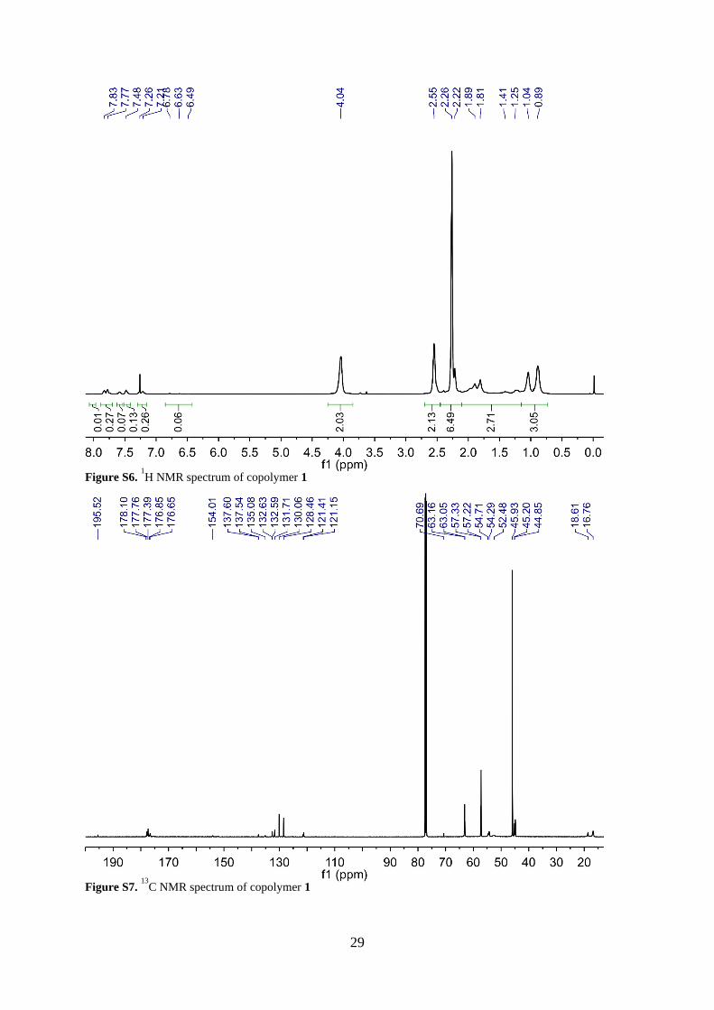
Figure S6. 1H NMR spectrum of copolymer 1
Figure S7. 13
C NMR spectrum of copolymer 1
Page 30
30
Supplementary Videos
Video S1. A helical MSP (copolymer 1, helix radius r = 38 m) in pH 1 buffer solution with
one end fixed to the substrate surface in contact with a PFD droplet (R = 132 m). As the
Figure S8. 1H NMR spectrum of copolymer 2
Figure S8. GPC traces of copolymers 1 and 2.
Page 31
31
substrate with adhered MSP end is translated to the left, the coiled helical MSP stretches until
it detaches from the droplet surface and recoils through the solution.
Video S2. A helical MSP (copolymer 1, helix radius r = 55 m) in pH 4 buffer solution with
one end fixed to the substrate surface in contact with a PFD droplet (R = 335 m). As the
substrate with adhered MSP end is translated to the left, the coiled helical MSP stretches until
4 coils detach from the droplet surface (time T ~ 2.3 s). Upon further stretching, the droplet is
pulled from the microcapillary tip by the adhered MSP spring.
Video S3. A helical MSP (copolymer 1) in pH 6 buffer solution. The left end of the helix is
attached to the substrate, while the right end became fixed to the substrate after release,
affording a structure with 2 fixed ends. As a PFD droplet is brought into contact with the helical
ribbon, the two bodies slide past each other without apparent adhesion.
Video S4. A short MSP segment (copolymer 1, length ~ 400 m) in pH 8 buffer solution is
adhered at one end to the surface of a droplet and at the far end to the substrate. Ribbon and
droplet are manipulated through the solution via microcapillary tip and translating stage,
revealing selective adhesion at the ribbon tip.
Video S5. MSPs (copolymer 1) in pH 10 buffer solution wrapped around a droplet. The droplet
is anchored in place by the fixed end of a wrapped ribbon, while the microcapillary tube and
translating stage are used to “unwrap” the droplet.
Video S6. An MSP (copolymer 1) is held in tension by the microcapillary tip to control
wrapping in pH 10 buffer solution. As slack is added to the system by bringing the MSP end
toward the wrapped droplet, the MSP continues to wrap until it overlaps an existing coil,
arresting the wrapping event.
Video S7. A droplet is inflated next to an MSP (copolymer 1) in pH 10 buffer solution. To the
left (out of frame), the MSP is fixed to the substrate surface; to the right it floats freely. When
the droplet touches the MSP, spontaneous wrapping occurs until a defect in the ribbon causes
self-overlap, stopping the wrapping event before the ribbon length is consumed and creating a
droplet with a pendent arm. To the left, wrapping continues until the ribbon is pulled tight
against the substrate-adhered end.
Video S8. A droplet is inflated until it comes into contact with an MSP (copolymer 1) in pH 10
buffer solution. The ribbon is fixed to the substrate to the left (out of frame) and floats freely to
the right. Upon contact, the ribbon spontaneously wraps the droplet until the free end is
consumed and the ribbon is pulled tight against the substrate-bound end to the left, final droplet
radius R = 360 m.
Video S9. An MSP (copolymer 1) in pH 10 buffer with one end adhered to the substrate surface
(left, out of frame) is partially wrapped around a droplet (R = 88 m) that is adhered to a
superglue bead near the end of a carbon fiber cantilever. The ribbon-droplet and cantilever-
droplet interfaces are loaded by translating the substrate to the left to pull on the ribbon.
Cantilever deflection is used to quantify the applied loads as the system is loaded, unloaded,
and then loaded until detachment of the ribbon from the droplet surface.
Page 32
32
Video S10. Copolymer 2 MSBCP with 500 m block length has selectively wrapped a droplet
(R = 110 m) in pH 10 buffer solution to afford a droplet with a single arm extended into
solution.
Video S11. An MSBCP in pH 10 buffer solution attached to the same droplet as in Video S11
via selective wrapping to add a second arm.
Video S12. More MSBCPs in pH 10 buffer solution adhered to and selectively wrapped around
the same droplet as in Videos S10 and S11. In this case, we observe mixed assembly modes,
including end-on adhesion, adhesion of the hydrophilic segment without wrapping (R < Rc),
and selective segmental wrapping of the hydrophobic block (R > Rc).
Video S13. MSBCPs are picked up from the substrate using a PFD droplet (R = 150 m)
adhered to the microcapillary tip in 500 mM NaOH solution.
Video S14. Cantilever deflection of an MSBCP (patterned segment length 50 m) with one end
adhered to the substrate surface, and a far segment adhered to a cantilever-bound droplet (R =
60 m). The system is twice subjected to a full cycle of loading until peel initiation and
unloading until re-wrap. On the third cycle, peel is initiated, then propagated until complete
detachment of the adhered segment.
References for Supplementary Information
[1] Z. Zhang, F. Torok, J. Li, M. Bouchard, J. Victor, Photoactivatable Fouling-Resistant
Copolymers 2017.
[2] D. M. Barber, A. J. Crosby, T. Emrick, Adv. Mater. 2018, 30, 1706118.
[3] W. Lin, G. Ma, F. Ji, J. Zhang, L. Wang, H. Sun, S. Chen, J. Mater. Chem. B 2015, 3,
440.
[4] K. Masunaga, A. Tanaka, D. Domon, S. Watanabe, Y. Ohsawa, M. Ohashi, Chemically
amplified positive photoresist composition and pattern forming process 2010.
[5] M. H. Espinosa, P. J. O. del Toro, D. Z. Silva, In Polymer; 2001; Vol. 42, pp. 3393–
3397.
[6] J. T. Pham, J. Lawrence, D. Y. Lee, G. M. Grason, T. Emrick, A. J. Crosby, Adv.
Mater. 2013, 25, 6703.
[7] J. T. Pham, A. Morozov, A. J. Crosby, A. Lindner, O. du Roure, Phys. Rev. E 2015, 92,
011004.
[8] M. Kim, T. R. Powers, Phys. Rev. E 2005, 71, 021914.
Page 33
33
[9] F. M. White, I. Corfield, Viscous Fluid Flow; 3rd ed.; McGraw-Hill: New York, 2006.
[10] M. K. Jawed, P. M. Reis, Soft Matter 2016, 12, 1898.
[11] L. Koens, E. Lauga, Phys. Fluids 2016, 28, 013101.
[12] A. Emileh, E. Vasheghani-Farahani, M. Imani, Eur. Polym. J. 2007, 43, 1986.
[13] N. Orakdogen, J. Polym. Res. 2012, 19, 9914.
[14] L. Pain, C. Le Cornec, C. Rosilio, P. J. Paniez, Microelectron. Eng. 1996, 30, 271.
[15] C. Liu, M. Cheng, J. Micro/Nanolithography, MEMS, MOEMS 2005, 4, 033001.