ABSTRACTThis application report provides information on how to select the right chirp parameters in a fast FMCWRadar device based on the end application and use case, and program them optimally on TI’s radardevices.
Contents1 Introduction ................................................................................................................... 22 Impact of Chirp Configuration on System Parameters.................................................................. 23 Chirp Configurations for Common Applications.......................................................................... 74 Configurable Chirp RAM and Chirp Profiles.............................................................................. 75 Chirp Timing Parameters ................................................................................................... 86 Advanced Chirp Configurations .......................................................................................... 117 Basic Chirp Configuration Programming Sequence ................................................................... 128 References .................................................................................................................. 14
List of Figures
1 Typical FMCW Chirp ........................................................................................................ 22 Typical Frame Structure .................................................................................................... 23 Angle Estimation Basics .................................................................................................... 54 Example Antenna Gain Pattern ............................................................................................ 55 Effective Recevier Channels in MIMO Radar ............................................................................ 66 Chirp and Profile RAM Memory Allocation ............................................................................... 87 Example Usage of the Ramp Timing Calculator ....................................................................... 108 Sub Frame Structure Showing Three Bursts Looped Twice (start index having an offset of 2) ................. 119 Example of Advanced Frame Configuration of Two Sub Frames ................................................... 1210 Radar Configuration Sequence........................................................................................... 12
List of Tables
1 Example Chirp Configurations for Typical Applications................................................................. 72 Chirp Timing Parameters ................................................................................................... 83 Typical Synthesizer Ramp Down Times for Different Modulation Bandwidths ...................................... 94 Typical IF/DFE Filtering Latencies as a Function of DFE Mode and Output Sampling Rate .................... 10
TrademarksAll trademarks are the property of their respective owners.
1 IntroductionFrequency Modulated Continuous Wave (FMCW) mmWave radar sensors are becoming increasinglypopular for multiple automotive and industrial applications. The system requirements and care-abouts ineach of these applications could be very different. Range requirement, range resolution, max velocityrequirement, sensor field of view, data memory, processor MIPS, and so forth are some of the aspectsthat need to be analyzed based on the end application. Understanding the relationships between theFMCW chirp configuration and system performance parameters helps in selecting the right chirpconfigurations.
TI’s mmwave radar devices (MMIC) provide large flexibility in configuring chirp parameters and also allowmultiple chirp configurations in a single frame. The timing parameters are accurately controlled by thedigital timing engine and a built-in radio processor without heavy real-time software interference. Thisdocument describes the programming of chirp parameters and explains the various system considerationsthat determine the values for these parameters.
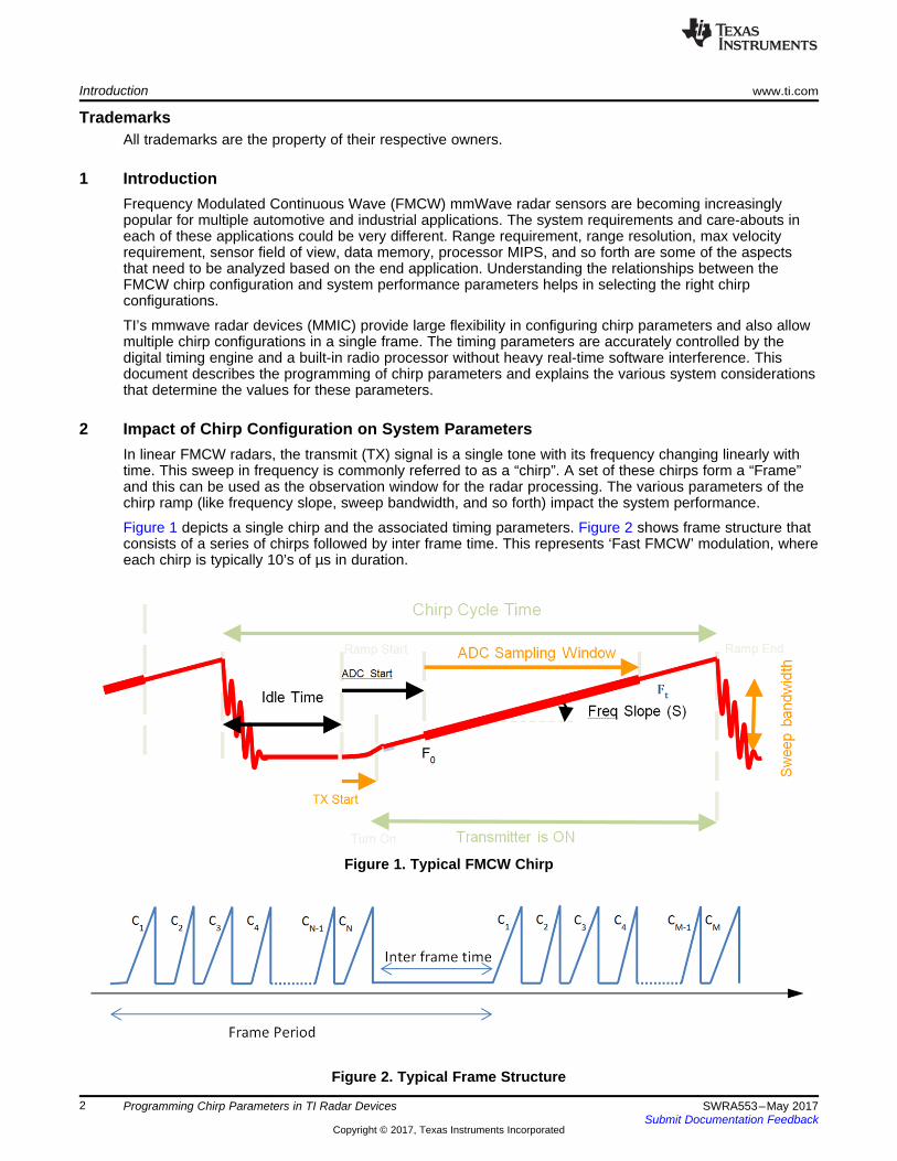
2 Impact of Chirp Configuration on System ParametersIn linear FMCW radars, the transmit (TX) signal is a single tone with its frequency changing linearly withtime. This sweep in frequency is commonly referred to as a “chirp”. A set of these chirps form a “Frame”and this can be used as the observation window for the radar processing. The various parameters of thechirp ramp (like frequency slope, sweep bandwidth, and so forth) impact the system performance.
Figure 1 depicts a single chirp and the associated timing parameters. Figure 2 shows frame structure thatconsists of a series of chirps followed by inter frame time. This represents ‘Fast FMCW’ modulation, whereeach chirp is typically 10’s of µs in duration.
The following sections list key system performance parameters that are typically considered in any radarapplication and how the chirp configuration impacts each one of them.
2.1 Measurement Range and Range ResolutionThe maximum and minimum distance over which a radar sensor can detect objects is an importantparameter for a radar sensor. Also, the range resolution (ability to distinguish two nearby objects) isanother important metric.
2.1.1 Maximum RangeIn applications like automotive adaptive cruise control (ACC), it’s important to be able to view a far offobject (>150m). Detecting a far-off object can be limited by either the SNR of the received signal or the IFbandwidth supported by the Radar device.
The max range relationship with the IF bandwidth is shown in Equation 1. TI’s AWR1243 radar deviceprovides a large 15 MHz bandwidth, allowing more flexibility in the slope that can be used, which indirectlyhelps increase the max velocity as will be seen later.
(1)
IFmax → Maximum IF bandwidth supportedc → Speed of lightS → Slope of the transmitted chirp
Note that the IFmax is also dependent on the ADC sampling frequency (ADCsampling) used. In a complex 1xsampling mode, the IF bandwidth is limited to 0.9* (ADCsampling). In case of complex 2x and real samplingmodes, the IF bandwidth is limited to 0.9* (ADCsampling)/2 . The maximum ADC sampling frequency in theTI’s radar devices is 37.5 Mhz.
The other aspect that could limit the max range is the signal to noise ratio (SNR) of signal received by thereceiver. This depends on:• RF performance of the Radar device, like TX output power, RX noise figure, as well as chirp
parameters like chirp duration and number of chirps in the frame.• Antenna parameters like the TX and RX antenna gain in the direction of interest.• Object characteristics like Radar Cross Section (RCS). RCS is a measure of the amount of energy the
object reflects back. This decides how detectable the object is with a radar sensor.• Minimum SNR required by the detection algorithm to detect an object.
(2)
Pt → Tx output powerGRx ,GTx → RX and TX Antenna gainσ → RCS of the objectN → Number of chirpsTr → Chirp timeNF → Noise figure of the receiverSNRdet → Minimum SNR required by the algorithum to detect an objectk → Boltzman constantTdet → Ambient temperature
2.1.2 Range ResolutionIn many applications it is important to be able to resolve two closely spaced objects as two separateobjects, rather than detect them as one. The smallest distance between two objects that allows them to bedetected as separate objects is referred to as range resolution. This primarily depends on the chirp sweepbandwidth that the radar sensor can provide. The larger the sweep bandwidth, the better the rangeresolution. TI’s radar devices support a 4 GHz sweep bandwidth that allows a range resolution of as lowas approximately 4cm.
(3)
c → Speed of lightB → Sweep bandwidth of FMCW chirp
Better range resolution also helps in detecting very close by objects, hence, improving a minimumdetection range.
2.2 Measurement Velocity and Velocity Resolution
2.2.1 Maximum VelocityAlong with the distance, the relative velocity of the object is another critical parameter of interest. Themaximum measurable velocity in Fast FMCW modulated radars depends on the chirp cycle time, that is,the time difference between the start of two consecutive chirps. This in turn depends on how fast thefrequency sweep can be performed and the minimum inter-chirp time allowed.
The faster the MMIC can ramp the frequency, the higher the maximum unambiguous velocity. TI’s MMICallows a fast ramp of 100 MHz/µs. Also the closed loop PLL is designed to support a very fast settling ofthe frequency ramp. Hence, the time taken for the VCO to jump from the end of the ramp frequency torestart the next ramp is very low and allows for a smaller idle time (as low as 2 µsec). For minimum idletime computation, see Section 5.
(4)
Tc → Total Chirp time ,which inlcudes chirp time+idle timeƛ → Wavelength of the signal used
The actual measurable max velocity can be extended beyond the unambiguous max velocity using higherlevel algorithm.
2.2.2 Velocity ResolutionIn applications, like park assist, you might need to separate out objects with small velocity differences, forwhich good velocity resolution is needed. Velocity resolution mostly depends on the transmit frameduration, that is, increasing the number of chirps in a frame improves the velocity resolution.
(5)
Nc → Number of Chirp in a frame
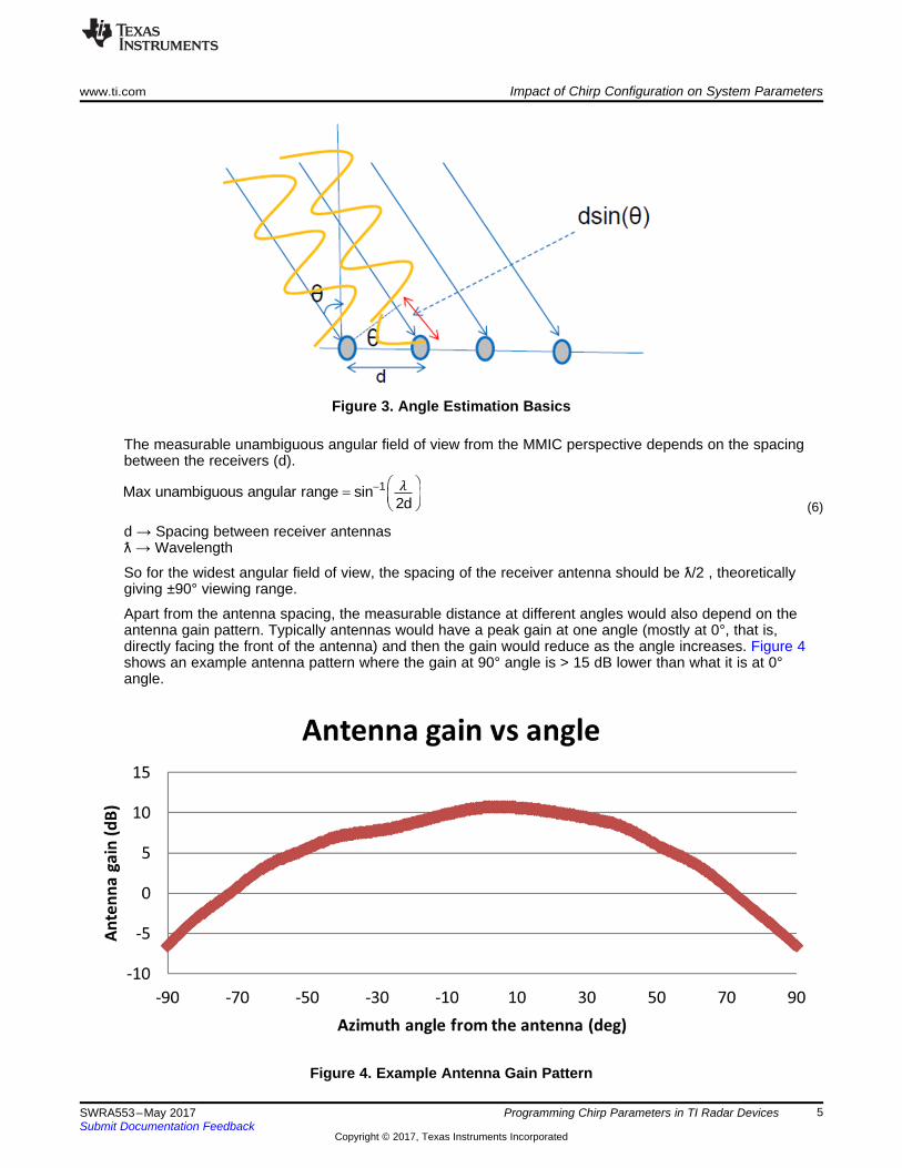
2.3 Angular Range and ResolutionIn order to locate the object in the 2D space, the angle of the object is also required along with thedistance. In a radar system, the angle is estimated by receiving the reflected signal from the object usingmultiple receivers that are spaced apart with a distance ‘d’. The signal arriving at each of the successive
receivers is delayed by d*sin(θ) and this “delay” causes a phase shift of . This phase shiftbetween each of the receivers is used to estimate the angle (θ) of the object.
The measurable unambiguous angular field of view from the MMIC perspective depends on the spacingbetween the receivers (d).
(6)
d → Spacing between receiver antennasƛ → Wavelength
So for the widest angular field of view, the spacing of the receiver antenna should be ƛ/2 , theoreticallygiving ±90° viewing range.
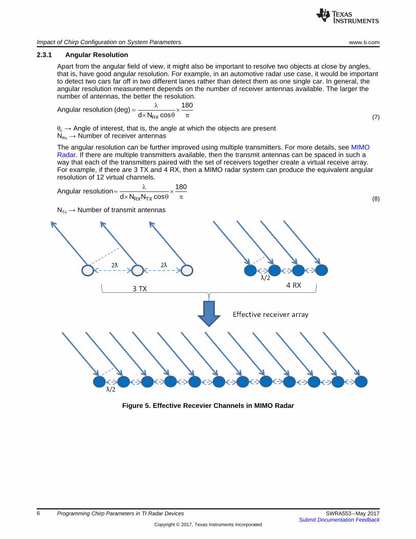
Apart from the antenna spacing, the measurable distance at different angles would also depend on theantenna gain pattern. Typically antennas would have a peak gain at one angle (mostly at 0°, that is,directly facing the front of the antenna) and then the gain would reduce as the angle increases. Figure 4shows an example antenna pattern where the gain at 90° angle is > 15 dB lower than what it is at 0°angle.
2.3.1 Angular ResolutionApart from the angular field of view, it might also be important to resolve two objects at close by angles,that is, have good angular resolution. For example, in an automotive radar use case, it would be importantto detect two cars far off in two different lanes rather than detect them as one single car. In general, theangular resolution measurement depends on the number of receiver antennas available. The larger thenumber of antennas, the better the resolution.
(7)
θc → Angle of interest, that is, the angle at which the objects are presentNRx → Number of receiver antennas
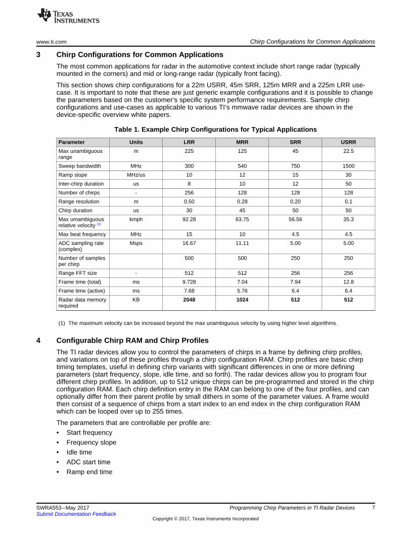
The angular resolution can be further improved using multiple transmitters. For more details, see MIMORadar. If there are multiple transmitters available, then the transmit antennas can be spaced in such away that each of the transmitters paired with the set of receivers together create a virtual receive array.For example, if there are 3 TX and 4 RX, then a MIMO radar system can produce the equivalent angularresolution of 12 virtual channels.
(8)
NTx → Number of transmit antennas
Figure 5. Effective Recevier Channels in MIMO Radar
3 Chirp Configurations for Common ApplicationsThe most common applications for radar in the automotive context include short range radar (typicallymounted in the corners) and mid or long-range radar (typically front facing).
This section shows chirp configurations for a 22m USRR, 45m SRR, 125m MRR and a 225m LRR use-case. It is important to note that these are just generic example configurations and it is possible to changethe parameters based on the customer’s specific system performance requirements. Sample chirpconfigurations and use-cases as applicable to various TI’s mmwave radar devices are shown in thedevice-specific overview white papers.
Table 1. Example Chirp Configurations for Typical Applications
Parameter Units LRR MRR SRR USRRMax unambiguousrange
Max beat frequency MHz 15 10 4.5 4.5ADC sampling rate(complex)
Msps 16.67 11.11 5.00 5.00
Number of samplesper chirp
500 500 250 250
Range FFT size - 512 512 256 256Frame time (total) ms 9.728 7.04 7.94 12.8Frame time (active) ms 7.68 5.76 6.4 6.4Radar data memoryrequired
KB 2048 1024 512 512
(1) The maximum velocity can be increased beyond the max unambiguous velocity by using higher level algorithms.
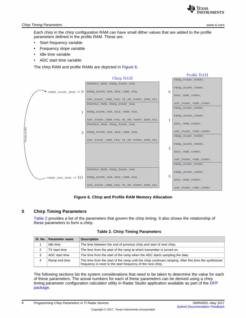
4 Configurable Chirp RAM and Chirp ProfilesThe TI radar devices allow you to control the parameters of chirps in a frame by defining chirp profiles,and variations on top of these profiles through a chirp configuration RAM. Chirp profiles are basic chirptiming templates, useful in defining chirp variants with significant differences in one or more definingparameters (start frequency, slope, idle time, and so forth). The radar devices allow you to program fourdifferent chirp profiles. In addition, up to 512 unique chirps can be pre-programmed and stored in the chirpconfiguration RAM. Each chirp definition entry in the RAM can belong to one of the four profiles, and canoptionally differ from their parent profile by small dithers in some of the parameter values. A frame wouldthen consist of a sequence of chirps from a start index to an end index in the chirp configuration RAMwhich can be looped over up to 255 times.
The parameters that are controllable per profile are:• Start frequency• Frequency slope• Idle time• ADC start time• Ramp end time
Each chirp in the chirp configuration RAM can have small dither values that are added to the profileparameters defined in the profile RAM. These are:• Start frequency variable• Frequency slope variable• Idle time variable• ADC start time variable
The chirp RAM and profile RAMs are depicted in Figure 6.
Figure 6. Chirp and Profile RAM Memory Allocation
5 Chirp Timing ParametersTable 2 provides a list of the parameters that govern the chirp timing. It also shows the relationship ofthese parameters to form a chirp.
Table 2. Chirp Timing Parameters
Sl. No. Parameter name Description1 Idle time The time between the end of previous chirp and start of next chirp.2 TX start time The time from the start of the ramp at which transmitter is turned on.3 ADC start time The time from the start of the ramp when the ADC starts sampling the data.4 Ramp end time The time from the start of the ramp until the chirp continues ramping. After this time the synthesizer
frequency is reset to the start frequency of the next chirp.
The following sections list the system considerations that need to be taken to determine the value for eachof these parameters. The actual numbers for each of these parameters can be derived using a chirptiming parameter configuration calculator utility in Radar Studio application available as part of the DFPpackage.
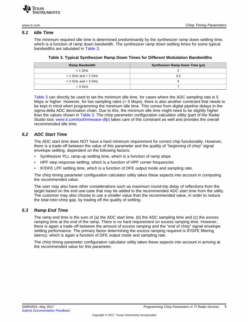
5.1 Idle TimeThe minimum required idle time is determined predominantly by the synthesizer ramp down settling time,which is a function of ramp down bandwidth. The synthesizer ramp down settling times for some typicalbandwidths are tabulated in Table 3.
Table 3. Typical Synthesizer Ramp Down Times for Different Modulation Bandwidths
Ramp Bandwidth Synthesizer Ramp Down Time (µs)< 1 GHz 2
> 1 GHz and < 2 GHz 3.5> 2 GHz and < 3 GHz 5
> 3 GHz 7
Table 3 can directly be used to set the minimum idle time, for cases where the ADC sampling rate is 5Msps or higher. However, for low sampling rates (< 5 Msps), there is also another constraint that needs tobe kept in mind when programming the minimum idle time. This comes from digital pipeline delays in thesigma-delta ADC decimation chain. Due to this, the minimum idle time might need to be slightly higherthan the values shown in Table 3. The chirp parameter configuration calculator utility (part of the RadarStudio tool, www.ti.com/tool/mmwave-dfp) takes care of this constraint as well and provides the overallrecommended idle time.
5.2 ADC Start TimeThe ADC start time does NOT have a hard minimum requirement for correct chip functionality. However,there is a trade-off between the value of this parameter and the quality of “beginning of chirp” signalenvelope settling, dependent on the following factors:• Synthesizer PLL ramp-up settling time, which is a function of ramp slope• HPF step response settling, which is a function of HPF corner frequencies• IF/DFE LPF settling time, which is a function of DFE output mode and sampling rate.
The chirp timing parameter configuration calculator utility takes these aspects into account in computingthe recommended value.
The user may also have other considerations such as maximum round-trip delay of reflections from thetarget based on the end use-case that may be added to the recommended ADC start time from the utility.The customer may also choose to use a smaller value than the recommended value, in order to reducethe total inter-chirp gap, by trading off the quality of settling.
5.3 Ramp End TimeThe ramp end time is the sum of (a) the ADC start time, (b) the ADC sampling time and (c) the excessramping time at the end of the ramp. There is no hard requirement on excess ramping time. However,there is again a trade-off between the amount of excess ramping and the “end of chirp” signal envelopesettling performance. The primary factor determining the excess ramping required is IF/DFE filteringlatency, which is again a function of DFE output mode and sampling rate.
The chirp timing parameter configuration calculator utility takes these aspects into account in arriving atthe recommended value for this parameter.
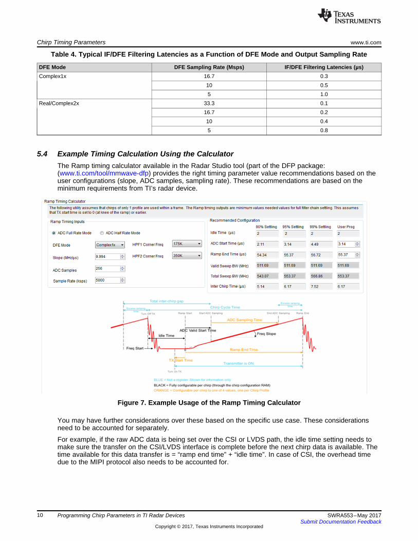
5.4 Example Timing Calculation Using the CalculatorThe Ramp timing calculator available in the Radar Studio tool (part of the DFP package:(www.ti.com/tool/mmwave-dfp) provides the right timing parameter value recommendations based on theuser configurations (slope, ADC samples, sampling rate). These recommendations are based on theminimum requirements from TI’s radar device.
Figure 7. Example Usage of the Ramp Timing Calculator
You may have further considerations over these based on the specific use case. These considerationsneed to be accounted for separately.
For example, if the raw ADC data is being set over the CSI or LVDS path, the idle time setting needs tomake sure the transfer on the CSI/LVDS interface is complete before the next chirp data is available. Thetime available for this data transfer is = “ramp end time” + “idle time”. In case of CSI, the overhead timedue to the MIPI protocol also needs to be accounted for.
6.1 Multi-Mode Radar ApplicationsAs you have seen that based on the desired application the chirp configurations need to be set differently.But what if we need to support multiple modes, for example short range and mid-range, simultaneouslyusing a single radar device? The advanced frame configuration available in TI’s radar allows for largeflexibility to have multiple chirp configurations in a single frame. The frame can be constituted using asequence of “sub-frames” with each of these sub-frames representing a different radar mode. TherlSetAdvFrameConfig API helps enable this kind of configuration. For details, see the “AWR1XXX RadarInterface Control Document” in the DFP package: www.ti.com/tool/mmwave-dfp).
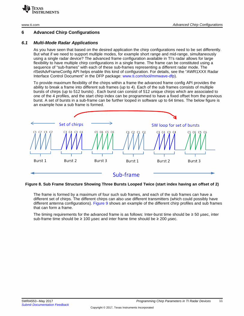
To provide maximum flexibility of the chirps within a frame the advanced frame config API provides theability to break a frame into different sub frames (up to 4). Each of the sub frames consists of multiplebursts of chirps (up to 512 bursts) . Each burst can consist of 512 unique chirps which are associated toone of the 4 profiles, and the start chirp index can be programmed to have a fixed offset from the previousburst. A set of bursts in a sub-frame can be further looped in software up to 64 times. The below figure isan example how a sub frame is formed.
Figure 8. Sub Frame Structure Showing Three Bursts Looped Twice (start index having an offset of 2)
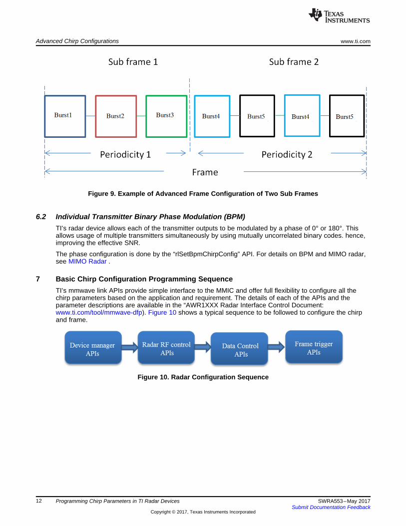
The frame is formed by a maximum of four such sub frames, and each of the sub frames can have adifferent set of chirps. The different chirps can also use different transmitters (which could possibly havedifferent antenna configurations). Figure 9 shows an example of the different chirp profiles and sub framesthat can form a frame.
The timing requirements for the advanced frame is as follows: Inter-burst time should be ≥ 50 µsec, intersub-frame time should be ≥ 100 µsec and inter frame time should be ≥ 200 µsec.
Figure 9. Example of Advanced Frame Configuration of Two Sub Frames
6.2 Individual Transmitter Binary Phase Modulation (BPM)TI’s radar device allows each of the transmitter outputs to be modulated by a phase of 0° or 180°. Thisallows usage of multiple transmitters simultaneously by using mutually uncorrelated binary codes. hence,improving the effective SNR.
The phase configuration is done by the “rlSetBpmChirpConfig” API. For details on BPM and MIMO radar,see MIMO Radar .
7 Basic Chirp Configuration Programming SequenceTI’s mmwave link APIs provide simple interface to the MMIC and offer full flexibility to configure all thechirp parameters based on the application and requirement. The details of each of the APIs and theparameter descriptions are available in the “AWR1XXX Radar Interface Control Document:www.ti.com/tool/mmwave-dfp). Figure 10 shows a typical sequence to be followed to configure the chirpand frame.
7.1 Device Manager APIsThese APIs are used to power on and initialize the sensor:• rlDevicePowerOn
This function initializes the driver and does the necessary resource allocation for the driver. It initializesthe host protocol driver by creating the necessary OS services like semaphore, mutex, queues and soforth. It also brings radar devices (multiple devices in case of cascade) out of reset and opens thecommunication channel (SPI, Mailbox, and so forth) with these devices.
• rlDeviceRfStartThis function initializes the RF (BIST) subsystem in the radar device. The function returns immediatelyand RF initialization completion is indicated by the asynchronous event(RL_EVENT_AR_DEVICE_START_COMPLETE). User application should wait for this event beforeinvoking any Radar Sensor Control APIs.
• DeviceFileDownloadThis function downloads a binary file from the host to the internal RAM of the radar device. This filecould be a firmware patch file, application code, calibration data or configuration data.
7.2 Radar RF Control APIsThese APIs are used to configure the RF parameters, chirp profiles and frame configurations.• rlSetChannelConfig
This API allows configuring of the number of TX antennas (out of 3) and number of RX antennas (outof 4) to be used. It also allows the selection of whether they are using the sensor in standalone modeor cascade mode.
• rlSetAdcOutConfigThis API allows configuring of the number of bits per sample (12/14/16). It also allows the choice ofwhether the ADC data should be real only, Complex -1x or Complex- 2x.
• rlSetLowPowerModeConfigThis API allows the setting of a low power ADC mode for power saving. In this mode, the maximumADC sampling rate is limited.
• rlSetProfileConfigThis API allows configuring the chirp “profile”, which defines a template for a chirp. Theseconfigurations include chirp start frequency, idle time, ADC start time, chirp slope, chirp duration, TXpower level in the chirp, number of ADC samples per chirp, the ADC sampling rate, High pass filter(HPF) cutoff frequencies and RX gain setting. Up to four profiles can be defined and in a particularframe (which can have up to 512 unique chirps) the chirps in the frame can belong to any of these fourprofiles. Since a single profile may not suffice all the intended use cases of the sensor, having flexibilityto have multiple profiles allows usage of a single sensor in multiple scenarios/use cases.
• rlSetChirpConfigOnce the profiles are defined, each of the unique chirps can be associated to one of these profiles.Apart from this, the API also allows limited chirp to chirp variations (beyond the profiles) in some of theimportant parameters like start frequency, idle time and ADC start time. The API also allows selectingthe transmitters to be used in that particular chirp.
• rlSetFrameConfig
This API allows selecting the sequence of the chirps that form the frame, number of frames that need tobe transferred and the periodicity of the frames. The periodicity would define the inter-frame time(periodicity – chirptime), hence, the duty cycle of the transmission. The frame could be software APItriggered (via rlSensorStart API ) or externally triggered using the SYNC_IN signal. In case of the HWtrigger option, a programmable delay can be set from the SYNC_IN edge.
7.3 Radar Data Control APIsThe ADC data captured during the chirps is transferred out of the device on the high speed debuginterface or CSI. The data control APIs allow configuring the ADC data that needs to be transferred outand the high speed interface (LVDS/CSI) configurations. Along with the ADC data, some additionalinformation related to the quality of the chirp and chirp parameters (that are referred to as CQ (chirpquality) and CP (chirp parameter), respectively) can also be transferred out. The LVDS/ CSIconfigurations, lane configurations, and so forth can be done using these APIs. For details on these APIsand the parameters, see the “AWR1XXX Radar Interface Control Document” (part of the DFP package:www.ti.com/tool/mmwave-dfp).
7.4 Frame Trigger APIOnce the chirps and frames are configured, they can be triggered either via a software API or hardwaretriggered using the digital SYNC_IN signal. The software API to trigger the frame is rlSensorStart.
IMPORTANT NOTICE FOR TI DESIGN INFORMATION AND RESOURCES
Texas Instruments Incorporated (‘TI”) technical, application or other design advice, services or information, including, but not limited to,reference designs and materials relating to evaluation modules, (collectively, “TI Resources”) are intended to assist designers who aredeveloping applications that incorporate TI products; by downloading, accessing or using any particular TI Resource in any way, you(individually or, if you are acting on behalf of a company, your company) agree to use it solely for this purpose and subject to the terms ofthis Notice.TI’s provision of TI Resources does not expand or otherwise alter TI’s applicable published warranties or warranty disclaimers for TIproducts, and no additional obligations or liabilities arise from TI providing such TI Resources. TI reserves the right to make corrections,enhancements, improvements and other changes to its TI Resources.You understand and agree that you remain responsible for using your independent analysis, evaluation and judgment in designing yourapplications and that you have full and exclusive responsibility to assure the safety of your applications and compliance of your applications(and of all TI products used in or for your applications) with all applicable regulations, laws and other applicable requirements. Yourepresent that, with respect to your applications, you have all the necessary expertise to create and implement safeguards that (1)anticipate dangerous consequences of failures, (2) monitor failures and their consequences, and (3) lessen the likelihood of failures thatmight cause harm and take appropriate actions. You agree that prior to using or distributing any applications that include TI products, youwill thoroughly test such applications and the functionality of such TI products as used in such applications. TI has not conducted anytesting other than that specifically described in the published documentation for a particular TI Resource.You are authorized to use, copy and modify any individual TI Resource only in connection with the development of applications that includethe TI product(s) identified in such TI Resource. NO OTHER LICENSE, EXPRESS OR IMPLIED, BY ESTOPPEL OR OTHERWISE TOANY OTHER TI INTELLECTUAL PROPERTY RIGHT, AND NO LICENSE TO ANY TECHNOLOGY OR INTELLECTUAL PROPERTYRIGHT OF TI OR ANY THIRD PARTY IS GRANTED HEREIN, including but not limited to any patent right, copyright, mask work right, orother intellectual property right relating to any combination, machine, or process in which TI products or services are used. Informationregarding or referencing third-party products or services does not constitute a license to use such products or services, or a warranty orendorsement thereof. Use of TI Resources may require a license from a third party under the patents or other intellectual property of thethird party, or a license from TI under the patents or other intellectual property of TI.TI RESOURCES ARE PROVIDED “AS IS” AND WITH ALL FAULTS. TI DISCLAIMS ALL OTHER WARRANTIES ORREPRESENTATIONS, EXPRESS OR IMPLIED, REGARDING TI RESOURCES OR USE THEREOF, INCLUDING BUT NOT LIMITED TOACCURACY OR COMPLETENESS, TITLE, ANY EPIDEMIC FAILURE WARRANTY AND ANY IMPLIED WARRANTIES OFMERCHANTABILITY, FITNESS FOR A PARTICULAR PURPOSE, AND NON-INFRINGEMENT OF ANY THIRD PARTY INTELLECTUALPROPERTY RIGHTS.TI SHALL NOT BE LIABLE FOR AND SHALL NOT DEFEND OR INDEMNIFY YOU AGAINST ANY CLAIM, INCLUDING BUT NOTLIMITED TO ANY INFRINGEMENT CLAIM THAT RELATES TO OR IS BASED ON ANY COMBINATION OF PRODUCTS EVEN IFDESCRIBED IN TI RESOURCES OR OTHERWISE. IN NO EVENT SHALL TI BE LIABLE FOR ANY ACTUAL, DIRECT, SPECIAL,COLLATERAL, INDIRECT, PUNITIVE, INCIDENTAL, CONSEQUENTIAL OR EXEMPLARY DAMAGES IN CONNECTION WITH ORARISING OUT OF TI RESOURCES OR USE THEREOF, AND REGARDLESS OF WHETHER TI HAS BEEN ADVISED OF THEPOSSIBILITY OF SUCH DAMAGES.You agree to fully indemnify TI and its representatives against any damages, costs, losses, and/or liabilities arising out of your non-compliance with the terms and provisions of this Notice.This Notice applies to TI Resources. Additional terms apply to the use and purchase of certain types of materials, TI products and services.These include; without limitation, TI’s standard terms for semiconductor products http://www.ti.com/sc/docs/stdterms.htm), evaluationmodules, and samples (http://www.ti.com/sc/docs/sampterms.htm).