85
DIGITAL MONITORING PRODUCTS, INC. PROGRAMMING GUIDE
DIGITAL MONITORING PRODUCTS, INC.
PROGRAMMING GUIDE

b XR150/XR550 SERIES PROGRAMMING GUIDE | DIGITAL MONITORING PRODUCTS
MODEL XR150/XR550 SERIES PROGRAMMING GUIDE
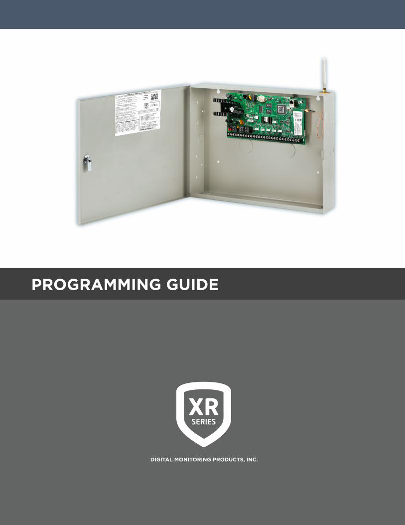
Contains programming Instructions for use with the Model XR150/XR550 Series Control Panels.
When using the XR150/XR550 Series panel for any listing organization’s approved methods, refer to the Compliance Listing Guide (LT-1330). This document outlines the installation and programming requirements of all applications for which XR150/XR550 Series control panels are approved.
© 2021 Digital Monitoring Products, Inc.
Information furnished by DMP is believed to be accurate and reliable.This information is subject to change without notice.

XR150/XR550 SERIES PROGRAMMING GUIDE | DIGITAL MONITORING PRODUCTS I
INTRODUCTION ......................................1XR Programming Information ............................1
Getting Started ........................................................1
Accessing the user menu .....................................1
Encrypted Communications ...............................1
Programmer Operation ........................................2
Programmer Lockout Codes ..............................2
Reset Timeout ..........................................................2
Keypads ......................................................................2
Special Keys ..............................................................3
Entering Alpha Characters ..................................3
Entering Non-Alpha Characters ........................4
Keypad Displays Current Programming ........4
Multiple Displays .....................................................4
Asterisks in Programming ...................................4
Compliance Instructions ......................................4
INITIALIZATION ......................................5
Initialization ...............................................................5
Clear All Memory ....................................................5
Clear All Codes ........................................................5
Clear All Schedules ................................................5
Clear Display Events Memory ............................5
Clear Zone Information ........................................5
Clear Area Information .........................................5
Clear Output Information ....................................5
Clear Communication and Remote Options 5
Clear Wi-Fi .................................................................5
Set to Factory Defaults ........................................5
Communication .......................................................6
Account Number .....................................................6
Transmit Delay .........................................................6
Communication Path .............................................6
Communication Type ............................................6
Test Report ................................................................6
Test Frequency ........................................................7
Test Day ......................................................................7
Test Time ....................................................................7
Check In ......................................................................7
Fail Time .....................................................................7
Encryption (XR550 with Encryption only) ...7
IPV6 Address ............................................................7
Receiver IP .................................................................7
Receiver Port ............................................................8
First Telephone Number ......................................8
Second Telephone Number ................................8
APN ..............................................................................8
Fail Test Hours ..........................................................8
Protocol ......................................................................8
Retry Seconds ..........................................................8
Substitution Code ...................................................8
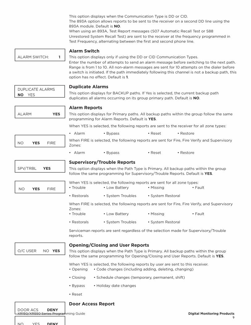
893A ............................................................................9
Alarm Switch ............................................................9
Duplicate Alarms .....................................................9
Alarm Reports ..........................................................9
Supervisory/Trouble Reports .............................9
Opening/Closing and User Reports ................9
Door Access Report ...............................................10
Panic Test (Network only) ...................................10
Send Communication Trouble ...........................10
Send Path Information ..........................................10
NETWORK OPTIONS ..............................11
Wi-Fi Setup ...............................................................11

II XR150/XR550 SERIES PROGRAMMING GUIDE | DIGITAL MONITORING PRODUCTS
WPS .............................................................................11
List ................................................................................11
Manual .........................................................................11
Test ...............................................................................12
Wireless Security Type .........................................12
Wireless Network Key ...........................................12
IPV6 ..............................................................................12
DHCP ...........................................................................12
Local IP Address ....................................................12
Gateway Address ....................................................12
Subnet Mask .............................................................12
DNS Server ................................................................12
Passphrase (XR550 with Encryption only)...13
734N Listen Port .....................................................13
734N Passphrase .....................................................13
DEVICE SETUP ........................................14
Device Setup ............................................................14
Custom Card Definitions ......................................14
Wiegand Code Length .........................................14
Site Code Position ..................................................14
Site Code Length ....................................................14
User Code Position.................................................14
User Code Length ...................................................14
Require Site Code ...................................................14
Number of User Code Digits ..............................15
Device Number ........................................................15
Device Name.............................................................16
Device Type ...............................................................16
Private Door ..............................................................16
1100T ...........................................................................17
Device Communication Type .............................17
Serial Number ..........................................................17
Supervision Time.....................................................17
Access Areas ............................................................17
Egress Areas .............................................................17
Display Areas ............................................................17
Strike Time .................................................................19
Strike Delay ...............................................................19
Fire Exit Release ......................................................19
Public Door................................................................19
Output Group ...........................................................19
Schedule Override ..................................................19
Auto Force Arm Device? ......................................19
Door Real-Time Status? ........................................20
Send Door Forced Message? .............................20
Program 734/734N Options ...............................20
Card Options ............................................................20
Activate Zone 2 Bypass ........................................20
Zone 2 Bypass Time...............................................20
Relock on Zone 2 Change? .................................20
Activate Zone 3 Request to Exit .......................21
Zone 3 REX Strike Time .......................................21
Activate Onboard Speaker ..................................21
No Communication with Panel ..........................21
REMOTE OPTIONS .................................22
Remote Options ......................................................22
Remote Key ...............................................................22
Remote Disarm ........................................................22
Armed Answer Rings ............................................22
Disarmed Answer Rings .......................................22
PC Modem .................................................................22
Alarm Receiver Authorization ...........................22

XR150/XR550 SERIES PROGRAMMING GUIDE | DIGITAL MONITORING PRODUCTS III
Service Receiver Authorization .........................22
Manufacturer Authorization ...............................23
Allow Network Remote ........................................23
Network Programming Port ...............................23
Encrypt Network Remote ....................................23
Allow Cellular Remote ..........................................23
APN ..............................................................................23
Encrypt Cellular Remote ......................................23
Entré Connection ....................................................23
Entré Incoming TCP Port .....................................23
Entré IP Address .....................................................23
Entré Outbound TCP Port ...................................23
Entré Backup Connection ...................................24
Entré Backup TCP Port .........................................24
Entré Reports ...........................................................24
Arm and Disarm Reports .....................................24
Zone Reports ............................................................24
User Command Reports .......................................24
Door Access Reports.............................................24
Supervisory Reports ..............................................24
Video Reports ..........................................................24
Entré Checkin ...........................................................24
Entré Passphrase ....................................................24
Integrator Connection...........................................25
Integrator Incoming TCP Port ............................25
Integrator IP Address ............................................25
Integrator Outbound TCP Port ..........................25
Integrator Backup Connection ..........................25
Integrator Backup TCP Port ...............................25
Integrator Reports ..................................................25
Arm and Disarm Reports .....................................25
Zone Reports ............................................................25
User Command Reports .......................................25
Door Access Reports.............................................25
Supervisory Reports ..............................................26
Integrator Passphrase ...........................................26
Send Local Changes ..............................................26
Remote Change IP .................................................26
Remote Change Port .............................................26
Remote Telephone Number ................................26
App Key ......................................................................26
System Reports .......................................................27
Abort Report ............................................................27
Restoral Reports .....................................................27
Bypass Reports ........................................................27
Schedule Change Reports ...................................27
Access Keypads .......................................................27
Ambush ......................................................................27
Late To Open ............................................................28
Early To Close ...........................................................28
Video Reports ..........................................................28
SYSTEM OPTIONS ..................................29
System Options .......................................................29
System .........................................................................29
Instant Arming .........................................................29
Closing Wait ..............................................................29
Entry Delay 1 .............................................................29
Cross Zone Time .....................................................30
Zone Retard Delay..................................................30
Power Fail Delay ......................................................30
Swinger Bypass Trips ............................................30
Reset Swinger Bypass ..........................................30
IV XR150/XR550 SERIES PROGRAMMING GUIDE | DIGITAL MONITORING PRODUCTS
Zone Activity Hours ...............................................30
Time Zone Changes ...............................................31
Latch Supervisory Zones .....................................31
Programming Menu Language ..........................31
User Menu and Status List Language .............32
Bypass Limit .............................................................32
House Code ...............................................................32
Wireless Encryption ...............................................32
Enter Passphrase ....................................................32
Detect Wireless Jamming ...................................33
Trouble Audible Annunciation ...........................33
Enable Keypad Panic Keys ..................................33
Occupied Premises ................................................33
Enhanced Zone Test ..............................................33
Send 16 Character Names ...................................33
Keypad Armed LED ...............................................34
Use False Alarm Question ...................................34
Allow Own User Code Change ..........................34
Panic Supervision ...................................................34
EOL Selection ...........................................................34
Celsius Temperature Option ...............................34
bELL OPTIONS ........................................35
Bell Options ..............................................................35
Bell Cutoff Time .......................................................35
Automatic Bell Test ................................................35
Bell Output ................................................................35
Bell Action .................................................................35
Fire Bell Action ........................................................35
Burglary Bell Action ...............................................35
Supervisory Bell Action ........................................35
Panic Bell Action .....................................................35
Emergency Bell Action .........................................35
Auxiliary 1 Bell Action ............................................35
Auxiliary 2 Bell Action ...........................................35
Carbon Monoxide (CO) ........................................35
OUTPUT OPTIONS ..................................36
Output Options .......................................................36
Cutoff Output ...........................................................36
Output Cutoff Time ................................................36
Communication Trouble Output .......................36
Fire Alarm Output ..................................................36
Fire Trouble Output ...............................................36
Panic Alarm Output ...............................................37
Ambush Output .......................................................37
Entry Output .............................................................37
Begin Exit Output ...................................................37
End Exit Output .......................................................37
Ready Output ...........................................................37
Armed Output ..........................................................37
Disarmed Output ....................................................37
Telephone Trouble Output ..................................37
Late To Close Output ............................................37
Device Fail Output..................................................38
Sensor Reset Output .............................................38
Closing Wait Output ..............................................38
Arm-Alarm Output .................................................38
Supervisory Alarm Output ..................................38
Heat Saver Temperature ......................................38
Cool Saver Temperature .......................................38
Carbon Monoxide Alarm Output ......................38
Lockdown Output Alarm Output .....................38
Output Information ................................................39

XR150/XR550 SERIES PROGRAMMING GUIDE | DIGITAL MONITORING PRODUCTS V
Output Number .......................................................39
Output Name ............................................................39
Output Real-Time Status......................................39
Serial Number ..........................................................39
Supervision Time.....................................................39
Trip with Panel Bell Option .................................39
Output Groups .........................................................40
Group Number .........................................................40
Group Name ..............................................................40
Output Number .......................................................40
MENU DISPLAY .......................................41
Menu Display ............................................................41
Armed Status ...........................................................41
Time .............................................................................41
Arm/Disarm ..............................................................41
STATUS LIST ............................................42
Status List ..................................................................42
Display Keypads ......................................................42
System Monitor Troubles .....................................42
Fire Zones ..................................................................42
Burglary Zones ........................................................42
Supervisory Zones ..................................................43
Panic Zones ...............................................................43
Emergency Zones ...................................................43
Auxiliary 1 Zones .....................................................43
Auxiliary 2 Zones ....................................................43
Carbon Monoxide Zones ......................................43
Communication Trouble .......................................43
PC LOG REPORTS ...................................44
PC Log Reports .......................................................44
Net IP Address .........................................................44
Net Port ......................................................................44
Arm and Disarm Reports .....................................44
Zone Reports ............................................................44
User Command Reports .......................................44
Door Access Reports.............................................44
Supervisory Reports ..............................................44
PC Log Real-Time Status .....................................45
AREA INFORMATION .............................46
Area Information .....................................................46
Exit Delay ...................................................................46
Closing Check ..........................................................46
Closing Code ............................................................46
Any Bypass ................................................................46
Area Schedules ........................................................46
Early Morning Ambush (Network panels only) 47
Area Number ............................................................47
All/Perimeter Programming ...............................47
Home/Sleep/Away Programming ....................47
Area Name .................................................................47
Account Number .....................................................47
Opening/Closing Reports ....................................47
Automatic Arming ..................................................48
Bad Zones ..................................................................48
Automatic Disarming ............................................48
Burglary Bell Output..............................................48
Armed Output Number ........................................48
Late Output Number .............................................48
Late Arm Delay ........................................................48
Bank Safe & Vault ...................................................49
Common Area ..........................................................49
VI XR150/XR550 SERIES PROGRAMMING GUIDE | DIGITAL MONITORING PRODUCTS
Arm First Area .........................................................49
Dual Authority ..........................................................49
Card Plus Pin.............................................................49
ZONE INFORMATION .............................50
Zone Information ....................................................50
Zone Number ...........................................................50
Zone Name ................................................................50
Area Assignment ....................................................51
Fire Bell Output .......................................................51
Arming Zone Area Assignment .........................52
Style .............................................................................52
Next Zone ..................................................................53
Wireless ......................................................................53
Competitor Wireless ..............................................53
Serial Number Entry ..............................................53
Contact .......................................................................53
Supervision Time.....................................................54
LED Operation .........................................................54
Disarm/Disable ........................................................54
PIR Pulse Count .......................................................54
PIR Sensitivity ..........................................................54
Pet Immunity ............................................................54
Next Zone ..................................................................54
1144 Series Key Fobs .............................................55
Key Fob User Number ..........................................55
Key Fob Serial Number ........................................55
Key Fob Supervision Time...................................55
Number of Key Fob Buttons ..............................55
Key Fob Button Selection (Four Buttons) ....55
Key Fob Button Selection (Two Buttons) .....55
Button Action ...........................................................56
Button Press Time ..................................................56
Arm/Disarm Area Selection ...............................56
Output Number .......................................................56
Output Action ..........................................................57
Next Zone ..................................................................57
V-Plex Serial Number Entry ................................57
Alarm Action .............................................................57
Disarmed Open ........................................................57
Report to Transmit .................................................57
Output Number .......................................................58
Output Action ..........................................................58
Swinger Bypass .......................................................58
Prewarn Keypad Addresses ................................59
Chime ..........................................................................59
Entry Delay ................................................................59
Zone Retard Delay..................................................59
Presignal Keypad Addresses ..............................59
Fast Response ..........................................................59
Cross Zone.................................................................59
Priority ........................................................................59
Fire Panel Slave Input............................................60
Area Follower ...........................................................60
Zone Real-Time Status ..........................................60
Traffic Count .............................................................60
Zone Audit Days ......................................................60
Report with Account Number for Area ..........60
Lockdown ..................................................................60
STOP .........................................................61
Stop ..............................................................................61

XR150/XR550 SERIES PROGRAMMING GUIDE | DIGITAL MONITORING PRODUCTS VII
SET LOCKOUT CODE .............................62
Set Lockout Code ...................................................62
FEATURE UPGRADE...............................63
Feature Upgrade .....................................................63
Encryption .................................................................63
All No Yes Option ...................................................63
Service User Authentication ...............................63
32 Door Add On A/ 32 Door Add On B .........63
APPENDIX................................................65
False Alarm Reduction .........................................65
Diagnostics Function.............................................65
Using the 984 Command Function .................67
Keypad Displays ......................................................68
Using the Walk Test ...............................................68
Walk Test ....................................................................68
Zone Types ................................................................68
Trip Counter For Walk Test .................................69
Trip Counter For DMP Wireless Check-in Test (WLS) ...........................................................................69
Test End Warning ....................................................70
Keypad Speaker Operation .................................70
Cross Zoning .............................................................70
User Profiles ..............................................................71
User Profiles Record ..............................................72
Wireless Check-in and Supervision .................72
Zone Type Descriptions .......................................73
Common Keypad Messages ...............................74
Area Account Number Messages .....................75

VIII XR150/XR550 SERIES PROGRAMMING GUIDE | DIGITAL MONITORING PRODUCTS
XR150/XR550 Series Programming Guide Digital Monitoring Products1
INTRODUCTIONXR PROGRAMMING INFORMATIONThis guide provides programming information for the DMP XR150/XR550 Series panel. Before starting to program, we recommend that you read through the contents of this guide.
In addition to this guide, you should also read and be familiar with the following documents:
• XR150/XR550 Series Installation Guide (LT-1233)
• XR150/XR550 Series Programming Sheet (LT-1234)
• XR150/XR550 Series Users Guide (LT-1278)
Internal ProgrammerThe panel contains all of its programming information in an on-board processor and does not require an external programmer. You can perform all programming tasks through a 32-character DMP alphanumeric keypad set to address one, or through Dealer Admin, Tech APP, and Remote Link.
GETTING STARTEDBefore starting to program the panel, make sure the panel is properly grounded and AC and battery power is applied to the appropriate panel terminals. All wiring connections and grounding instructions are detailed in the XR150/XR550 Series Installation Guide (LT-1233).
ACCESSING THE USER MENUXR Series panels ship with a unique four-digit default master code that is used to access the user menu for the first time. This code can be modified or deleted. In order to revert back to the default code 99, use the initialize code option found in panel programming. To access the User Menu:
1. Press the CMD key until MENU? NO YES displays.
2. Select YES. The keypad displays ENTER CODE. Enter your user code. You can now scroll down through the list of system features available to you.
bEGIN A PROGRAMMING SESSION1. Momentarily place the Reset jumper over both of the RESET pins to reset the panel.
2. Enter the code 6653 (PROG) and press CMD.
3. The keypad displays: PROGRAMMER.
ENCRYPTED COMMUNICATIONS (XR550 WITH ENCRYPTION ONLY)Some installations require secure data communications. Use a unique passphrase to enable encrypted communications and provide a secure means for data communications. See Network Options.
An XR550 panel with encryption communicates using 128-bit or 256-bit AES encryption. If you currently have an XR550 panel with network installed, you may purchase a separate feature key to activate encrypted communications using the Feature Upgrade process. Encrypted communication cannot be enabled on a standard XR550 panel. For more information on the Feature Upgrade process see Section 21 in this document.
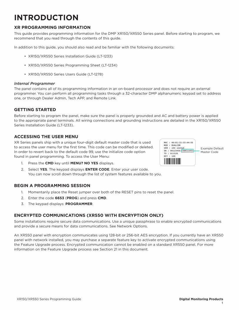
MAC : 00:01:22:33:44:55MOD : DUALCOMVER : 194 122319SN : 0012345A CODE21852TD : 011520KEY : 100
Example Default Master Code

Digital Monitoring Products XR150/XR550 Series Programming Guide2
PROGRAMMER OPERATIONThere are 20 programming sections to choose from:
Programming Item Section in This Manual Programming Item Section in This Manual
Initialization 2 Output Information 12
Communication 3 Output Groups 13
Network Options 4 Menu Display 14
Messaging Setup 5 Status List 15
Device Setup 6 PC Log Reports 16
Remote Options 7 Area Information 17
System Reports 8 Zone Information 18
System Options 9 Stop 19
Bell Options 10 Set Lockout Code 20
Output Options 11 Feature Upgrade 21
To choose a section for programming, press any select key or area when the keypad displays the name of that section. Sections 2 through 21. contain detailed instructions for each programming step.
PROGRAMMER LOCKOUT CODESThe panel allows you to enter the programming function without entering a lockout code using steps 1 to 4 listed in Getting Started. We recommend, however, that you install a Lockout Code to restrict programming to only those persons your company authorizes. You can do this by using the SET LOCKOUT CODE feature in the Programmer. The Lockout Code restricts any unauthorized panel programming.
After resetting the panel and entering the code 6653, the keypad displays PROGRAMMER. Press CMD to advance through the programming sections until SET LOCKOUT CODE displays (after STOP). Press any select key or area. The keypad displays ENTER CODE: – . Enter a 3 to 5 digit Programmer Lockout Code and press CMD. The keypad displays ENTER AGAIN followed by ENTER CODE: –. Enter the same 3 to 5 digit code a second time and press. The keypad displays CODE CHANGED. The panel does not accept a 5-digit Lockout Code higher than 65535.
Before accessing programmer functions enter the new code number. Write the Lockout Code number down and keep it in a secure place with access limited to authorized persons only. Lost Lockout Codes require the panel to be sent back to DMP for repair. You may cancel a Lockout Code by entering 00000 at the Set Lockout Code command.
RESET TIMEOUTThe panel has a feature that requires you to enter the Programmer within 30 minutes of resetting the panel. After 30 minutes, if you attempt to program by entering the 6653 (PROG) code, the keypad displays: RESET PANEL. You must reset the panel and enter the program code then begin programming within the next 30 minutes.
If you are already in the Programmer and do not press any keys on the programming keypad for 30 minutes, the panel terminates programming. All data entered up to that time is not saved unless you run the Stop routine.
Use the Stop routine to exit panel Programming. Ensure the keypad displays “SAVING PROGRAM” to save all programming changes entered.
POWER UPWhen the panel is powered up after an AC power failure, any zone transitions are not recognized for 60 seconds. Normal zone processing resumes at the end of the 60 seconds.
KEYPADSDMP offers multiple keypads in a variety of styles that provide programming capabilities. Each keypad and its operation are shown and described in the following sections. See Figures 2 through 4.
XR150/XR550 Series Programming Guide Digital Monitoring Products3
SPECIAL KEYSThe following special keys/areas are common to all DMP keypads.
COMMAND (CMD) KeyPressing CMD allows you to go forward through the programming menu and through each step of a programming sec-tion. As you go through the programming, the keypad display shows any current programming already stored in the panel memory. If no change is required for an option, press CMD to advance to the next step.
CMD is also used to enter information into the panel’s memory such as phone numbers or zone names. Press CMD after entering information.
Back Arrow (<—) KeyUse the Back Arrow key to back up one step while programming. The Back Arrow key is also used when an error is made while entering in formation. Press the Back Arrow key once to erase the last character entered.
Select Keys or AreasThe top row of keys are called the select keys on Thinline and Aqualite keypads or select areas on Graphic Touchscreen keypads. Each time you need to press a select key or area, the keypad displays the function or options above one of the keys or in the select area. Displaying choices above individual select keys or in select areas allows them to be used for many different applications. For example, you can enter AM or PM when programming the automatic test time or answer YES or NO for a system option.
During programming, the select keys or areas also allow you to change infor mation currently in panel memory by pressing the appropriate select key or area under or on the display. You then enter the new information using the keypad data entry digit keys.
When there are more than four re sponse options avail able, press CMD to display the remaining options. Pressing the Back Arrow key allows you to review the previous four choices.
The select keys or areas are also used for choosing a section from the pro gramming menu. Press any select key or touch the select area when the programming section name you want displays.
On Wireless, Thinline and Aqualite keypads, when instructed to press the first select key, press the far left select key; the second select key is the second from the left; third select key is second from the right; and the fourth select key is the far right key.
On Graphic Touchscreen Keypads, when instructed to press the first select key, touch select area 1; the second select key touch select area 2; third select key touch select area 3; and the fourth select key touch select area 4.
ENTERING ALPHA CHARACTERSSome options during programming require you to enter alpha characters. To enter an alpha character, press or touch the key that has that letter written below it. The keypad displays the number digit of the key. Next, press the select key or area that corresponds to the loca tion of the letter under the key. Pressing a different select key or area changes the letter. When an other digit key is pressed, the last letter displayed is retained and the process starts over.

Digital Monitoring Products XR150/XR550 Series Programming Guide4
ENTERING NON-ALPHA CHARACTERSTo enter a space in an alpha entry, press the 9 digit key followed by the third select key or area. The three characters on the 9 digit key are Y, Z, and space. You can also enter the following characters: – (dash), . (period), * (asterisk), and # (pound sign) using the 0 (zero) key and the four select key or area from left to right. For example, to enter a – (dash), press the 0 (zero) key and then the left select key or area. A dash now appears in the keypad display. The table below shows the character locations for DMP keypads.
Key Number Select Key or Area 1
Select Key or Area 2
Select Key or Area 3
Select Key or Area 4
1 A B C (2 D E F )3 G H I !4 J K L ?5 M N O /6 P Q R &
7 S T U @8 V W X ,9 Y Z space _0 - . * #
KEYPAD DISPLAYS CURRENT PROGRAMMINGEach programming option displayed at the keypad shows the currently selected option in the panel memory. These options are either shown as a number, a blank, or a NO or YES. To change a number or blank to a new number, press any select key or touch any select area. The current option is replaced with a dash.
Press the number(s) on the keypad you want to enter as the new number for that option. It is not necessary to enter numbers with leading zeros. The panel automatically right justifies the number when you press CMD.
To change a programming option that requires a NO or YES response, press the select key or touch the select area for the response not selected.
For example, if the current option is selected as YES and you want to change it to NO, on Thinline or Aqualite keypads press the third select key. On Graphic Touchscreen keypads touch select area 3. The display changes to NO. Press CMD to display the next option.
MULTIPLE DISPLAYSFor many programming and user options, such as Area selections, Menu Displays, and Status Lists, there are several displays containing programming. For example, when programming Menu Displays, keypads 1 through 16 display on two separate displays. First, keypads 1 through 8 display. Press CMD to display keypads 9 through 16. This same scheme is used for areas 1 through 32. Areas not pre-programmed at installation to display at this keypad cannot be viewed.
ASTERISKS IN PROGRAMMINGAsterisks display next to a programming option that is already selected. As shown in the example, options that are selected to display the current programming selection have an asterisk next to the number. Those that are not selected simply display the number. In the Devices example, keypads 3, 8, 9, and 15 are not selected. In the Areas example, areas 3, 8, 9, 15, 19, 23, 25, and 31 are not selected. In both examples the numbers with asterisks are selected.
To select or deselect a number, simply enter the number using the digit keys on the keypad. This same scheme is used when viewing the panel armed status and other programming and operational functions. Remember to press CMD to display the rest of the device or area numbers.
COMPLIANCE INSTRUCTIONSThis product incorporates field-programmable software. Refer to the XR150/XR550 Compliance Listing Guide (LT-1330) for additional compliance information.
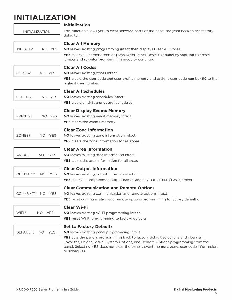
INITIALIZATIONInitializationThis function allows you to clear selected parts of the panel program back to the factory defaults.
Clear All MemoryNO leaves existing programming intact then displays Clear All Codes.
YES clears all memory then displays Reset Panel. Reset the panel by shorting the reset jumper and re-enter programming mode to continue.
Clear All CodesNO leaves existing codes intact.
YES clears the user code and user profile memory and assigns user code number 99 to the highest user number.
Clear All SchedulesNO leaves existing schedules intact.
YES clears all shift and output schedules.
Clear Display Events MemoryNO leaves existing event memory intact.
YES clears the events memory.
Clear Zone InformationNO leaves existing zone information intact.
YES clears the zone information for all zones.
Clear Area InformationNO leaves existing area information intact.
YES clears the area information for all areas.
Clear Output InformationNO leaves existing output information intact.
YES clears all programmed output names and any output cutoff assignment.
Clear Communication and Remote OptionsNO leaves existing communication and remote options intact.
YES reset communication and remote options programming to factory defaults.
Clear Wi-FiNO leaves existing Wi-Fi programming intact.
YES reset Wi-Fi programming to factory defaults.
Set to Factory DefaultsNO leaves existing panel programming intact.
YES sets the panel’s programming back to factory default selections and clears all Favorites, Device Setup, System Options, and Remote Options programming from the panel. Selecting YES does not clear the panel’s event memory, zone, user code information, or schedules.
INITIALIZATION
INITIALIZATION
INIT ALL? NO YES
CODES? NO YES
SCHEDS? NO YES
EVENTS? NO YES
ZONES? NO YES
AREAS? NO YES
OUTPUTS? NO YES
COM/RMT? NO YES
WIFI? NO YES
DEFAULTS NO YES
XR150/XR550 Series Programming Guide Digital Monitoring Products5
INITIALIZATIONInitializationThis function allows you to clear selected parts of the panel program back to the factory defaults.
Clear All MemoryNO leaves existing programming intact then displays Clear All Codes.
YES clears all memory then displays Reset Panel. Reset the panel by shorting the reset jumper and re-enter programming mode to continue.
Clear All CodesNO leaves existing codes intact.
YES clears the user code and user profile memory and assigns user code number 99 to the highest user number.
Clear All SchedulesNO leaves existing schedules intact.
YES clears all shift and output schedules.
Clear Display Events MemoryNO leaves existing event memory intact.
YES clears the events memory.
Clear Zone InformationNO leaves existing zone information intact.
YES clears the zone information for all zones.
Clear Area InformationNO leaves existing area information intact.
YES clears the area information for all areas.
Clear Output InformationNO leaves existing output information intact.
YES clears all programmed output names and any output cutoff assignment.
Clear Communication and Remote OptionsNO leaves existing communication and remote options intact.
YES reset communication and remote options programming to factory defaults.
Clear Wi-FiNO leaves existing Wi-Fi programming intact.
YES reset Wi-Fi programming to factory defaults.
Set to Factory DefaultsNO leaves existing panel programming intact.
YES sets the panel’s programming back to factory default selections and clears all Favorites, Device Setup, System Options, and Remote Options programming from the panel. Selecting YES does not clear the panel’s event memory, zone, user code information, or schedules.
INITIALIZATION
INITIALIZATION
INIT ALL? NO YES
CODES? NO YES
SCHEDS? NO YES
EVENTS? NO YES
ZONES? NO YES
AREAS? NO YES
OUTPUTS? NO YES
COM/RMT? NO YES
WIFI? NO YES
DEFAULTS NO YES
Digital Monitoring Products XR150/XR550 Series Programming Guide6
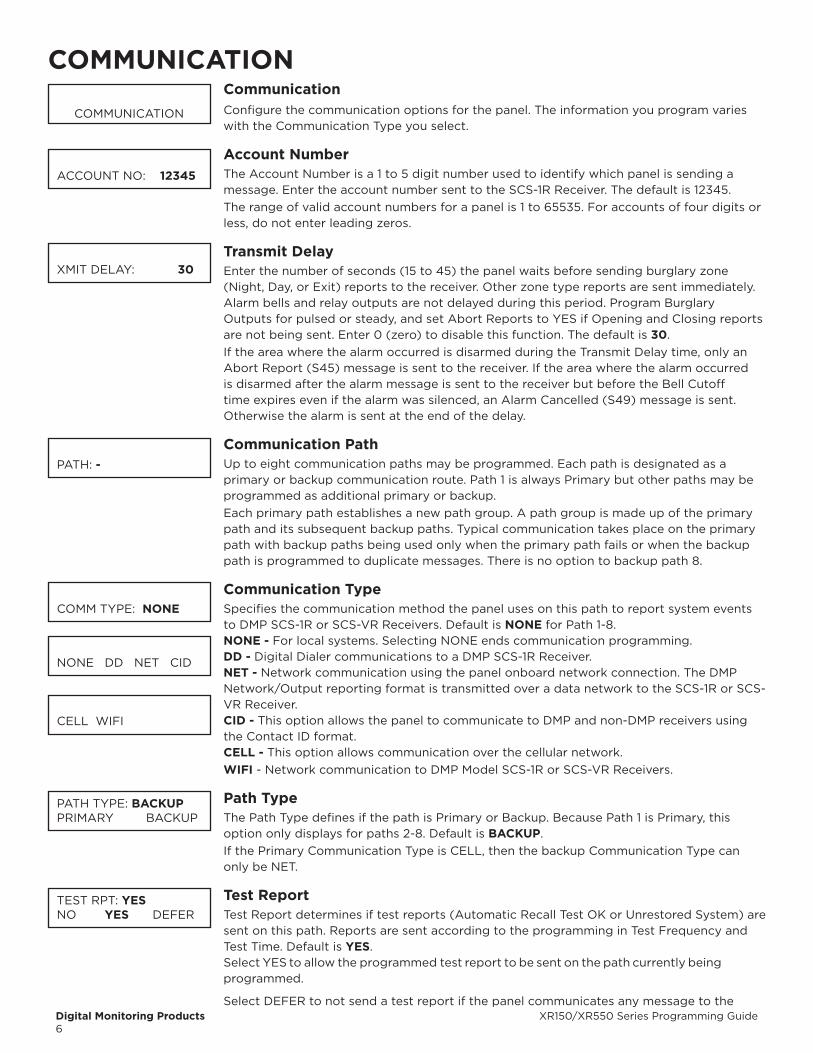
COMMUNICATIONCommunicationConfigure the communication options for the panel. The information you program varies with the Communication Type you select.
Account NumberThe Account Number is a 1 to 5 digit number used to identify which panel is sending a message. Enter the account number sent to the SCS-1R Receiver. The default is 12345.The range of valid account numbers for a panel is 1 to 65535. For accounts of four digits or less, do not enter leading zeros.
Transmit DelayEnter the number of seconds (15 to 45) the panel waits before sending burglary zone (Night, Day, or Exit) reports to the receiver. Other zone type reports are sent immediately. Alarm bells and relay outputs are not delayed during this period. Program Burglary Outputs for pulsed or steady, and set Abort Reports to YES if Opening and Closing reports are not being sent. Enter 0 (zero) to disable this function. The default is 30.If the area where the alarm occurred is disarmed during the Transmit Delay time, only an Abort Report (S45) message is sent to the receiver. If the area where the alarm occurred is disarmed after the alarm message is sent to the receiver but before the Bell Cutoff time expires even if the alarm was silenced, an Alarm Cancelled (S49) message is sent. Otherwise the alarm is sent at the end of the delay.
Communication PathUp to eight communication paths may be programmed. Each path is designated as a primary or backup communication route. Path 1 is always Primary but other paths may be programmed as additional primary or backup.Each primary path establishes a new path group. A path group is made up of the primary path and its subsequent backup paths. Typical communication takes place on the primary path with backup paths being used only when the primary path fails or when the backup path is programmed to duplicate messages. There is no option to backup path 8.
Communication TypeSpecifies the communication method the panel uses on this path to report system events to DMP SCS-1R or SCS-VR Receivers. Default is NONE for Path 1-8.NONE - For local systems. Selecting NONE ends communication programming.DD - Digital Dialer communications to a DMP SCS-1R Receiver.NET - Network communication using the panel onboard network connection. The DMP Network/Output reporting format is transmitted over a data network to the SCS-1R or SCS-VR Receiver.CID - This option allows the panel to communicate to DMP and non-DMP receivers using the Contact ID format.CELL - This option allows communication over the cellular network.WIFI - Network communication to DMP Model SCS-1R or SCS-VR Receivers.
Path TypeThe Path Type defines if the path is Primary or Backup. Because Path 1 is Primary, this option only displays for paths 2-8. Default is bACKUP.If the Primary Communication Type is CELL, then the backup Communication Type can only be NET.
Test ReportTest Report determines if test reports (Automatic Recall Test OK or Unrestored System) are sent on this path. Reports are sent according to the programming in Test Frequency and Test Time. Default is YES.Select YES to allow the programmed test report to be sent on the path currently being programmed.
Select DEFER to not send a test report if the panel communicates any message to the
COMMUNICATION
ACCOUNT NO: 12345
XMIT DELAY: 30
PATH: -
COMM TYPE: NONE
NONE DD NET CID
CELL WIFI
PATH TYPE: bACKUPPRIMARY BACKUP
TEST RPT: YESNO YES DEFER
XR150/XR550 Series Programming Guide Digital Monitoring Products7
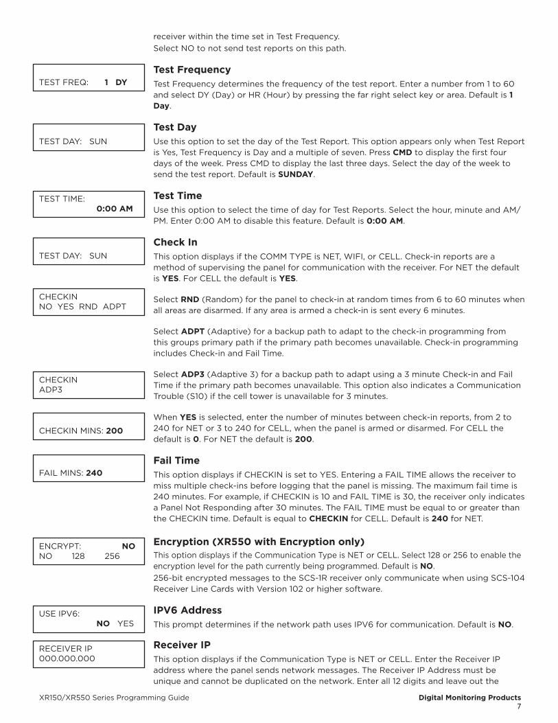
receiver within the time set in Test Frequency. Select NO to not send test reports on this path.
Test FrequencyTest Frequency determines the frequency of the test report. Enter a number from 1 to 60 and select DY (Day) or HR (Hour) by pressing the far right select key or area. Default is 1 Day.
Test DayUse this option to set the day of the Test Report. This option appears only when Test Report is Yes, Test Frequency is Day and a multiple of seven. Press CMD to display the first four days of the week. Press CMD to display the last three days. Select the day of the week to send the test report. Default is SUNDAY.
Test TimeUse this option to select the time of day for Test Reports. Select the hour, minute and AM/PM. Enter 0:00 AM to disable this feature. Default is 0:00 AM.
Check InThis option displays if the COMM TYPE is NET, WIFI, or CELL. Check-in reports are a method of supervising the panel for communication with the receiver. For NET the default is YES. For CELL the default is YES.
Select RND (Random) for the panel to check-in at random times from 6 to 60 minutes when all areas are disarmed. If any area is armed a check-in is sent every 6 minutes.
Select ADPT (Adaptive) for a backup path to adapt to the check-in programming from this groups primary path if the primary path becomes unavailable. Check-in programming includes Check-in and Fail Time.
Select ADP3 (Adaptive 3) for a backup path to adapt using a 3 minute Check-in and Fail Time if the primary path becomes unavailable. This option also indicates a Communication Trouble (S10) if the cell tower is unavailable for 3 minutes.
When YES is selected, enter the number of minutes between check-in reports, from 2 to 240 for NET or 3 to 240 for CELL, when the panel is armed or disarmed. For CELL the default is 0. For NET the default is 200.
Fail TimeThis option displays if CHECKIN is set to YES. Entering a FAIL TIME allows the receiver to miss multiple check-ins before logging that the panel is missing. The maximum fail time is 240 minutes. For example, if CHECKIN is 10 and FAIL TIME is 30, the receiver only indicates a Panel Not Responding after 30 minutes. The FAIL TIME must be equal to or greater than the CHECKIN time. Default is equal to CHECKIN for CELL. Default is 240 for NET.
Encryption (XR550 with Encryption only)This option displays if the Communication Type is NET or CELL. Select 128 or 256 to enable the encryption level for the path currently being programmed. Default is NO.256-bit encrypted messages to the SCS-1R receiver only communicate when using SCS-104 Receiver Line Cards with Version 102 or higher software.
IPV6 AddressThis prompt determines if the network path uses IPV6 for communication. Default is NO.
Receiver IPThis option displays if the Communication Type is NET or CELL. Enter the Receiver IP address where the panel sends network messages. The Receiver IP Address must be unique and cannot be duplicated on the network. Enter all 12 digits and leave out the
TEST FREQ: 1 DY
TEST DAY: SUN
TEST TIME: 0:00 AM
TEST DAY: SUN
CHECKINNO YES RND ADPT
CHECKINADP3
CHECKIN MINS: 200
FAIL MINS: 240
ENCRYPT: NONO 128 256
USE IPV6: NO YES
RECEIVER IP 000.000.000

Digital Monitoring Products XR150/XR550 Series Programming Guide8
periods. For example, enter IP address 192.168.0.250 as 192168000250. The periods display automatically. If IPV6 is selected the receiver IP will need to be an IPV6 address. If changing from IPV6 YES to IPV6 NO, you will need to modify thier IP address to IPV4.
Receiver Port Enter the receiver port number. Valid range is 1 to 65,535. Default is 2001.
First Telephone NumberThis option displays only if the Communication Type is DD or CID.This is the first number the panel dials when sending reports to the receiver. Phone numbers can have two lines of 16 characters each to equal up to 32 characters.
Second Telephone NumberThe panel dials the second number when two successive tries using the first number fail. If the panel cannot reach the receiver after two attempts using the second number, it returns to the first number and makes two additional attempts. A total of ten dialing attempts are made using the first and second phone num bers.
Advanced ProgrammingSelect YES to enter the Advanced Programming menu for the communication path currently being programmed. Selecting NO ends programming of the current communication path and takes users back to the Communication Path option to program a secondary path.
APNEnter the first APN (Access Point Name). This allows an access point for cellular communication and is used to connect to a DNS network. The APN may contain two lines of 16 characters to equal 32 characters. Default is set to SECURECOM400.
Fail Test HoursThis option sets the frequency for a Backup or Adaptive path to send a test report when the closest previous path fails within its path group.If Fail Test Frequency is set to 0, test reports are sent only according to Test Report programming. Range is 0 to 24 hours. Default is 0.
ProtocolThis option displays only if Communication Type is NET.
Select TCP to communicate over the network using TCP protocol. Select UDP to communicate using UDP protocol. Default is TCP.
Retry SecondsThis option displays only when Communication type is NET.
Enter the number of seconds (between 6 and 15) the panel should wait before retrying to send a message to the receiver if an acknowledgment was not received. The panel retries as many times as possible for a period of one minute before sending a network trouble message. The default Retry Time is 6 seconds.
Substitution CodeThis option displays when the Communication Type is NET or CELL. The Panel Substitution Code increases the level of security by helping to ensure that the panel sending the message to the receiver has not been substituted by another panel. The default is NO.
Select YES to send a substitution code with every message.Select SHARED (SHR) to use the same substitution code that was used in the previous path.
893A
RECEIVER PORT 2001
FIRST PHONE NO:
SECOND PHONE NO:
ADVANCED? NO YES
APNSECURECOM400
FAIL TEST HRS: 0
PROTOCOL: TCP
RETRY SECONDS: 6
SUB CODE: NONO YES SHARED
893A: NO YES
XR150/XR550 Series Programming Guide Digital Monitoring Products9
This option displays when the Communication Type is DD or CID.The 893A option allows reports to be sent to the receiver on a second DD line using the 893A module. Default is NO.When using an 893A, Test Report messages (S07 Automatic Recall Test or S88Unrestored System Recall Test) are sent to the receiver at the frequency programmed in Test Frequency, alternating between the first and second phone line.
Alarm SwitchThis option displays only if using the DD or CID Communication Types.Enter the number of attempts to send an alarm message before switching to the next path. Range is from 1 to 10. All non-alarm messages are sent for 10 attempts on the dialer before a switch is initiated. If the path immediately following this channel is not a backup path, this option has no effect. Default is 1.
Duplicate AlarmsThis option displays for BACKUP paths. If Yes is selected, the current backup path duplicates all alarms occurring on its group primary path. Default is NO.
Alarm ReportsThis option displays for Primary paths. All backup paths within the group follow the same programming for Alarm Reports. Default is YES.
When YES is selected, the following reports are sent to the receiver for all zone types:
• Alarm • Bypass • Reset • Restore
When FIRE is selected, the following reports are sent for Fire, Fire Verify and Supervisory Zones:
• Alarm • Bypass • Reset • Restore
Supervisory/Trouble ReportsThis option displays when the Path Type is Primary. All backup paths within the group follow the same programming for Supervisory/Trouble Reports. Default is YES.
When YES is selected, the following reports are sent for all zone types:• Trouble • Low Battery • Missing • Fault
• Restorals • System Troubles • System Restoral
When FIRE is selected, the following reports are sent for Fire, Fire Verify, and Supervisory Zones:• Trouble • Low Battery • Missing • Fault
• Restorals • System Troubles • System Restoral
Serviceman reports are sent regardless of the selection made for Supervisory/Trouble reports.
Opening/Closing and User ReportsThis option displays when the Path Type is Primary. All backup paths within the group follow the same programming for Opening/Closing and User Reports. Default is YES.
When YES is selected, the following reports by user are sent to this receiver.• Opening • Code changes (including adding, deleting, changing)
• Closing • Schedule changes (temporary, permanent, shift)
• Bypass • Holiday date changes
• Reset
Door Access Report
ALARM SWITCH: 1
DUPLICATE ALARMS NO YES
ALARM YES
NO YES FIRE
SPV/TRBL YES
NO YES FIRE
O/C USER NO YES
DOOR ACS DENY
NO YES DENY
Digital Monitoring Products XR150/XR550 Series Programming Guide10
This option displays when the Path Type is Primary. All backup paths within the group follow the same programming for Door Access Reports. Default is DENY.
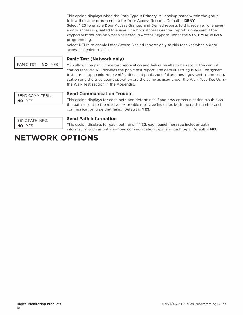
Select YES to enable Door Access Granted and Denied reports to this receiver whenever a door access is granted to a user. The Door Access Granted report is only sent if the keypad number has also been selected in Access Keypads under the SYSTEM REPORTS programming.Select DENY to enable Door Access Denied reports only to this receiver when a door access is denied to a user.
Panic Test (Network only)YES allows the panic zone test verification and failure results to be sent to the central station receiver. NO disables the panic test report. The default setting is NO. The system test start, stop, panic zone verification, and panic zone failure messages sent to the central station and the trips count operation are the same as used under the Walk Test. See Using the Walk Test section in the Appendix.
Send Communication Trouble This option displays for each path and determines if and how communication trouble on
the path is sent to the receiver. A trouble message indicates both the path number and communication type that failed. Default is YES.
Send Path Information This option displays for each path and if YES, each panel message includes path
information such as path number, communication type, and path type. Default is NO.
NETWORK OPTIONS
PANIC TST NO YES
SEND COMM TRBL: NO YES
SEND PATH INFO: NO YES

XR150/XR550 Series Programming Guide Digital Monitoring Products11
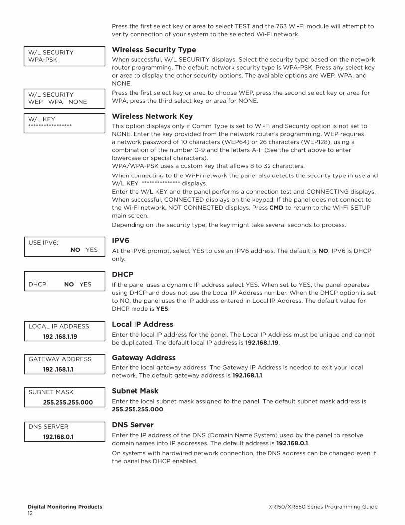
Network Options are provided to define the network configuration for the panel. This information will be used during communication of messages via network. A 763 Wi-Fi Module is required in order to send alarm signal communication.IP addresses and port numbers may need to be assigned by the network administrator. When entering an IP, Gateway, or Subnet Mask address be sure to enter all 12 digits and leave out the periods.
Wi-Fi SetupThis option is for connecting to the desired Wi-Fi network and will display only when Comm Type is set to Wi-Fi. Press any select key or area to select.
WPS - Automatically connects to a WPS enabled router. LIST - Displays the names and signal strength of any Wi-Fi routers in range. MANUAL - Enter the name of the Wi-Fi router you wish to connect to. TEST - Verifies connection of your system to the Wi-Fi network.
WPSWhen WPS is selected, SEARCHING displays. Press the WPS button on the Wi-Fi network router to which you are attempting to connect. SEARCHING displays for up to two minutes or until connected to the WPS enabled router. Refer to the router’s instruction manual for sending a security key to the XR150/XR550 Series panel.If the panel fails to connect to the WPS enabled router, WPS FAILED RETRY? NO YES displays. Press the fourth select key or area to RETRY or press the third select key or area to display WPS LIST MANUAL.
ListWhen LIST is selected, SEARCHING displays until any Wi-Fi networks are found in range. Once available Wi-Fi networks are found the keypad displays the name of the SSID (Wi-Fi Network name) and signal strength of each network. Press CMD to scroll through the list of available Wi-Fi networks. When the desired network is displayed, press any select key or area to connect.
ManualThis option allows you to enter the desired network name using the keypad. When MANUAL is selected, the current settings display. Press CMD to continue with no change. SecureCom is the default.Once the SSID is entered, press CMD and SEARCHING displays.When an SSID is entered for the first time or changed, the panel searches for the SSID entered to ensure communication. The keypad displays SSID FOUND or SSID NOT FOUND. When the SSID is found, the security type is also detected.Enter up to 32 characters for the SSID from the network router to identify the network LAN. The SSID is blank by default. Use the chart below to enter lowercase or special characters. Each successive press of the select key or area gives additional options.
Key Number Select Key or area 1
Select Key or area 2
Select Key or area 3
Select Key or area 4
1 A, a, B, b C, c (, [, {2 D, d E, e F, f ), ], }3 G, g H, h I, i !, ^, ~4 J, j K, k L, l ?, ", |5 M, m N, n O, o /, \, `6 P, p Q, q R, r &, $7 S, s T, t U, u @, %8 V, v W, w X, x , =9 Y, y Z, z space, : _, ;0 -, + ., ' *, < #, >
If the 763 is unable to connect to the desired network and SSID NOT FOUND displays, press CMD to return to the main menu and WPS LIST MANUAL displays. Press CMD again to display TEST.
Test
WPS LIST MANUALTEST
WPS LIST MANUALTEST
SEARCHING
WPS LIST MANUALSEARCHING
SIGNAL XXXXXXHOMENET123
WPS LIST MANUAL
WIFI SETUPENTER SSID
SSID SSID FOUND
SSID SSID NOT FOUND
TEST
Digital Monitoring Products XR150/XR550 Series Programming Guide12
Press the first select key or area to select TEST and the 763 Wi-Fi module will attempt to verify connection of your system to the selected Wi-Fi network.
Wireless Security TypeWhen successful, W/L SECURITY displays. Select the security type based on the network router programming. The default network security type is WPA-PSK. Press any select key or area to display the other security options. The available options are WEP, WPA, and NONE.
Press the first select key or area to choose WEP, press the second select key or area for WPA, press the third select key or area for NONE.
Wireless Network KeyThis option displays only if Comm Type is set to Wi-Fi and Security option is not set to NONE. Enter the key provided from the network router’s programming. WEP requires a network password of 10 characters (WEP64) or 26 characters (WEP128), using a combination of the number 0-9 and the letters A-F (See the chart above to enter lowercase or special characters).WPA/WPA-PSK uses a custom key that allows 8 to 32 characters.
When connecting to the Wi-Fi network the panel also detects the security type in use and W/L KEY: *************** displays.Enter the W/L KEY and the panel performs a connection test and CONNECTING displays. When successful, CONNECTED displays on the keypad. If the panel does not connect to the Wi-Fi network, NOT CONNECTED displays. Press CMD to return to the Wi-Fi SETUP main screen.
Depending on the security type, the key might take several seconds to process.
IPV6At the IPV6 prompt, select YES to use an IPV6 address. The default is NO. IPV6 is DHCP only.
DHCPIf the panel uses a dynamic IP address select YES. When set to YES, the panel operates using DHCP and does not use the Local IP Address number. When the DHCP option is set to NO, the panel uses the IP address entered in Local IP Address. The default value for DHCP mode is YES.
Local IP Address Enter the local IP address for the panel. The Local IP Address must be unique and cannot
be duplicated. The default local IP address is 192.168.1.19.
Gateway Address Enter the local gateway address. The Gateway IP Address is needed to exit your local
network. The default gateway address is 192.168.1.1.
Subnet Mask Enter the local subnet mask assigned to the panel. The default subnet mask address is
255.255.255.000.
DNS Server Enter the IP address of the DNS (Domain Name System) used by the panel to resolve
domain names into IP addresses. The default address is 192.168.0.1.
On systems with hardwired network connection, the DNS address can be changed even if the panel has DHCP enabled.
W/L SECURITYWPA-PSK
W/L SECURITYWEP WPA NONE
W/L KEY*****************
USE IPV6: NO YES
DHCP NO YES
LOCAL IP ADDRESS
192 .168.1.19
GATEWAY ADDRESS
192 .168.1.1
SUBNET MASK
255.255.255.000
DNS SERVER
192.168.0.1
XR150/XR550 Series Programming Guide Digital Monitoring Products13
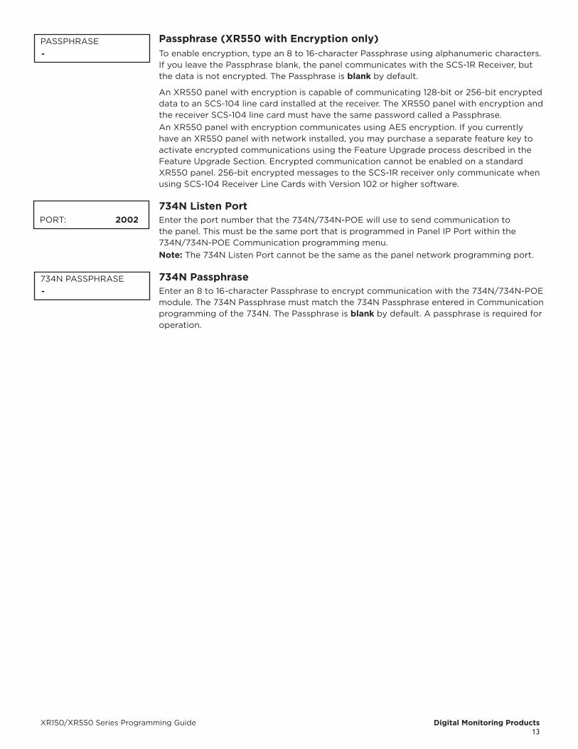
Passphrase (XR550 with Encryption only)To enable encryption, type an 8 to 16-character Passphrase using alphanumeric characters. If you leave the Passphrase blank, the panel communicates with the SCS-1R Receiver, but the data is not encrypted. The Passphrase is blank by default.
An XR550 panel with encryption is capable of communicating 128-bit or 256-bit encrypted data to an SCS-104 line card installed at the receiver. The XR550 panel with encryption and the receiver SCS-104 line card must have the same password called a Passphrase.An XR550 panel with encryption communicates using AES encryption. If you currently have an XR550 panel with network installed, you may purchase a separate feature key to activate encrypted communications using the Feature Upgrade process described in the Feature Upgrade Section. Encrypted communication cannot be enabled on a standard XR550 panel. 256-bit encrypted messages to the SCS-1R receiver only communicate when using SCS-104 Receiver Line Cards with Version 102 or higher software.
734N Listen Port Enter the port number that the 734N/734N-POE will use to send communication to
the panel. This must be the same port that is programmed in Panel IP Port within the 734N/734N-POE Communication programming menu.Note: The 734N Listen Port cannot be the same as the panel network programming port.
734N PassphraseEnter an 8 to 16-character Passphrase to encrypt communication with the 734N/734N-POE module. The 734N Passphrase must match the 734N Passphrase entered in Communication programming of the 734N. The Passphrase is blank by default. A passphrase is required for operation.
PASSPHRASE-
PORT: 2002
734N PASSPHRASE-

Digital Monitoring Products XR150/XR550 Series Programming Guide14
DEVICE SETUPDevice SetupThis section allows you to define the panels physical configuration. You can install and address up to sixteen supervised devices on the keypad bus. Devices can also be added to available LX-Busses. Programmable devices are Keypad, Door, Fire, Expander, 1100T, and V-PLEX.
Custom Card DefinitionsSelect the slot number (1-8) that you would like to program a custom non-DMP card format into. The format that is programmed into slot 1 is the default format. In the event that a card with an unrecognized format is used, that card will be read in the format that is programmed in slot 1. To restrict card reads to specific formats, only program slots 2-8. For a chart of commonly used card formats and their defaults, refer to the 734 Installation Guide (LT-0737) or 734N/734N-POE Installation Guide (LT-1197).
Select DMP to allow credentials that use a 26 - 45 bit data string.
Select CUSTOM to disable DMP format and program slots 1-8 as needed.
Select ANY to allow all card reads to activate the door strike relay. No user code information is sent to the panel.
If you select slot 1 and are updating an XR with firmware Version 182 or earlier, Format Name will automatically be named Single Card Format and Wiegand Code Length will default to 45.
Wiegand Code LengthWhen using a custom credential, enter the total number of bits to be received in Wiegand code including parity bits. Press any select key or area to enter a number between 1-255 to equal the number of bits. Default is 26 bits.The starting position location and code length must be determined and programmed into the 734/734N/734N-POE Module.
Site Code PositionEnter the site code start position in the data string. Press any select key or area to enter a number between 0-255. Default is 1.
Site Code LengthEnter the number of characters the site code contains. Press any select key or area to enter a number between 1-16. Default is 8.
User Code PositionDefine the User Code start bit position. Press any select key or area to enter a number between 0-255. Default is 9.
User Code LengthDefine the number of User Code bits. Press any select key or area to enter a custom number. On a 734 module, custom numbers can only be between 16-40. On a 734N/734N-POE module, custom numbers can be between 1-255. The default is 16.
Require Site CodePress the select key or area under YES to use a site code.
In addition to User Code verification, door access is only granted when any one site code programmed at the SITE CODE ENTRY option matches the site code received in the Wiegand string.
Site Code Display 734 Module: You can program up to 8 eight-digit site codes. Site code range is 0-16,777,214. Any previously programmed site codes display. Dashes represent blank site codes. Default is blank.
DEVICE SETUP
CARD OPTIONSDMP CUSTOM ANY
WIEGAND CODELENGTH: 26
SITE CODEPOSITION: 1
SITE CODELENGTH: 8
USER CODEPOSITION: 9
USER CODELENGTH: 16
REQUIRE SITECODE: NO YES
SITE CODE 1: -

XR150/XR550 Series Programming Guide Digital Monitoring Products15
734N/734N-POE Module: You can program up to 8 eight-digit site codes. Site code range is 0-16,777,214. Any previously programmed site codes display. Site Code 1 defaults to 127. Site Codes 2-8 default to blank. Site Code 1 displays first. Enter a site code number followed by the CMD key to advance to the next option, Site Code 2. To delete an existing site code, press any select key or area. Either enter a new site code followed by CMD, or press CMD to leave blank and continue to the next site code. Repeat these steps to change, delete, or add up to 8 site codes.
Number of User Code DigitsThe 734, 734N/734N-POE, and 734N-POE modules recognizes user codes from 4-12 digits in length. Press any select key or area to enter a user code digit length. This number must match the user code number length being used by the panel. Default is 5. For an Area System, use 4 to 12 digits. For all other XR Series panel configurations, use 4 digits.Any selection above 5 digits require entry of the custom card definitions with custom site and user code positions for the Wiegand string. When searching the bit string for the user code, the digits are identified and read from left to right.
Device NumberEnter the address of the device you are programming. After you program each option for the first device, repeat these programming steps for each additional device. Programmable devices are KEYPAD, DOOR, FIRE, EXPANDER, 1100T, and V-PLEX. The available addresses are 1 - 16 on the panel keypad bus, and 500 - 999 on the LX-Bus. The valid range for KEYPAD, FIRE, and EXPANDER type devices is 1 - 16 on the panel keypad bus. The valid range for DOOR type devices is 1 - 16 on the panel keypad bus and 501 - 961 on the AX-Bus.
See the AX Bus Addresses and 734 Zone Numbers chart on the next page. Wireless keypads and network door controllers are not able to occupy address 1.
AX-bus Operation for 734 Access Control Modules
Once a 734 address has been programmed for the bus, the LX-Bus is automatically converted from a hardwire zone expansion bus to a hardwire Access Expansion Bus (AX-Bus) and the bus begins to operate as shown below.
• Each 734 module provides one door relay and four protection zones to connect switches such as door and window contacts.
• 16 doors of access can be programmed per AX-Bus to a maximum of eighty (80) 734 modules. Please see the table below for available addresses.
• Any unused AX-Bus zone numbers may be programmed as wireless zones. Hardwired zone expansion modules such as the 711, 714, 715-16 and others are incompatible with bus operation and cannot be used.
• Device Setup programming for AX-Bus address are automatically programmed as a door type. Device Type, Communication Type and Display Areas are not shown. Only 734 module programming is shown.
An AX-Bus operation is compatible with 734, 734N, and 734N-POE modules and XR550 Series control panels. AX-Bus operation is incompatible with XR150 Series control panels.
SITE CODE 1: (0-16,777,214) 127
NO. OF USER CODE DIGITS 5
DEVICE NO: -

Digital Monitoring Products XR150/XR550 Series Programming Guide16
Device Addresses and 734, 734N, and 734N-POE Zone Numbers
Keypad bus LX/AX busDevice/
Door Zones Device/Door Zones Device/
Door Zones Device/Door Zones Device/
Door Zones Device/Door Zones
1 11-14 501 501-504 601 601-604 701 701-704 801 801-804 901 901-904
2 21-24 505 505-508 605 605-608 705 705-708 805 805-808 905 905-908
3 31-34 509 509-512 609 609-612 709 709-712 809 809-812 909 909-512
4 41-44 513 513-516 613 613-616 713 713-716 813 813-816 913 913-916
5 51-54 517 517-520 617 617-620 717 717-720 817 817-820 917 917-920
6 61-64 521 521-524 621 621-624 721 721-724 821 821-824 921 921-924
7 71-74 525 525-528 625 625-628 725 725-728 825 825-828 925 925-928
8 81-84 529 529-532 629 629-632 729 729-732 829 829-832 929 929-932
9 91-94 533 533-536 633 633-636 733 733-736 833 833-836 933 933-936
10 101-104 537 537-540 637 637-640 737 737-740 837 837-840 937 937-940
11 111-114 541 541-544 641 641-644 741 741-744 841 841-844 941 941-944
12 121-124 545 545-548 645 645-648 745 745-748 845 845-848 945 945-948
13 131-134 549 549-552 649 649-652 749 749-752 849 849-852 949 949-952
14 141-144 553 553-556 653 653-656 753 753-756 853 853-856 953 953-956
15 151-154 557 557-560 657 657-660 757 757-760 857 857-860 957 957-960
16 161-164 561 561-564 661 661-664 761 761-764 861 861-864 961 961-964
Device Addresses and 736V V-Plex Module Zone Numbers
Zones 96-99 on any LX-Bus that is connected to a 736V are diagnostic zones. For more information refer to the 736V V-Plex Advanced Settings Guide (LT-1934).
Device NameA device name must be given to each device in the system. To add a device name, press any select key or area. The default device name (DEVICE X) displays. Select CMD to accept the default name or press any select key or area to enter a new name up to 32 alphanumeric characters. Press CMD.To remove a device from the system, delete the device name by pressing any select key or area, then press CMD. The panel automatically programs the name as * UNUSED *.
Device TypeThis section allows you to select a device type for the selected device number.
DOOR - The device is an access control device and is either a keypad using door strike functions or a Wiegand Interface Module. Devices with an address higher than 16 are automatically assigned as a DOOR device type.
KEYPAD - The device type is a non-fire, non-access keypad.
FIRE - A 630F Remote Annunciator. See Fire Device Remote Programming in the XR550 Series Compliance Guide (LT-1330) for instructions on how to allow remote panel programming.
EXPANDER - A Zone Expansion Module.
VPX - A V-Plex device. The valid zones for VPX devices are 501, 601, 701, 801, and 901.
Private DoorSelect YES to assign this address as a private door, which will not be assigned to an access area. The private door can then be added to a profile. Up to four private doors can be assigned to an individual profile. Select NO to not allow a door to be designated as a private door. Default is NO.
XR150/XR550 XR550 OnlyDevice Zones Device Zones Device Zones Device Zones Device Zones
501 500-595 601 600-695 701 700-795 801 800-895 901 900-995
* UNUSED *
TYPE: KEYPADDOOR KPD FI EXP
VPX
PRIVATE DR NO YES
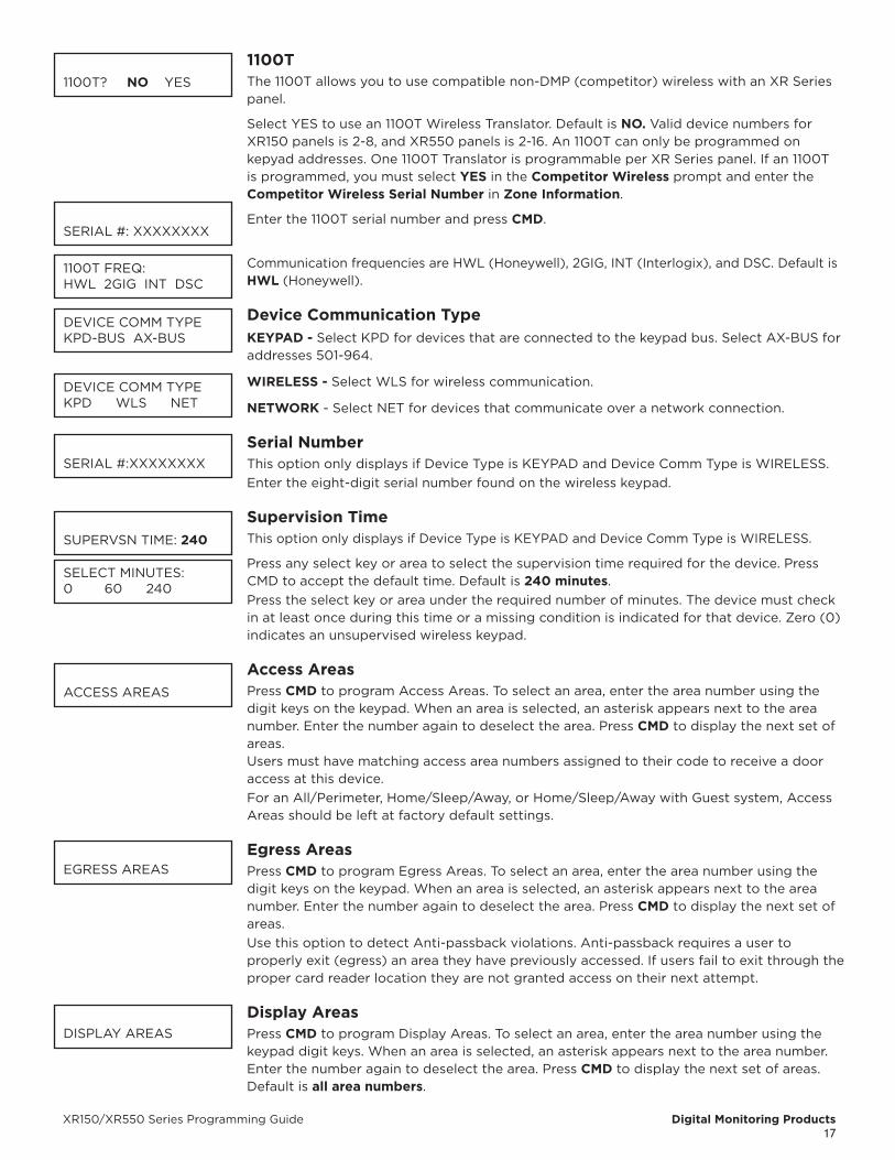
XR150/XR550 Series Programming Guide Digital Monitoring Products17
1100T The 1100T allows you to use compatible non-DMP (competitor) wireless with an XR Series panel.
Select YES to use an 1100T Wireless Translator. Default is NO. Valid device numbers for XR150 panels is 2-8, and XR550 panels is 2-16. An 1100T can only be programmed on kepyad addresses. One 1100T Translator is programmable per XR Series panel. If an 1100T is programmed, you must select YES in the Competitor Wireless prompt and enter the Competitor Wireless Serial Number in Zone Information.
Enter the 1100T serial number and press CMD.
Communication frequencies are HWL (Honeywell), 2GIG, INT (Interlogix), and DSC. Default is HWL (Honeywell).
Device Communication TypeKEYPAD - Select KPD for devices that are connected to the keypad bus. Select AX-BUS for addresses 501-964.
WIRELESS - Select WLS for wireless communication.
NETWORK - Select NET for devices that communicate over a network connection.
Serial NumberThis option only displays if Device Type is KEYPAD and Device Comm Type is WIRELESS.Enter the eight-digit serial number found on the wireless keypad.
Supervision TimeThis option only displays if Device Type is KEYPAD and Device Comm Type is WIRELESS.
Press any select key or area to select the supervision time required for the device. Press CMD to accept the default time. Default is 240 minutes.Press the select key or area under the required number of minutes. The device must check in at least once during this time or a missing condition is indicated for that device. Zero (0) indicates an unsupervised wireless keypad.
Access AreasPress CMD to program Access Areas. To select an area, enter the area number using the digit keys on the keypad. When an area is selected, an asterisk appears next to the area number. Enter the number again to deselect the area. Press CMD to display the next set of areas. Users must have matching access area numbers assigned to their code to receive a door access at this device.For an All/Perimeter, Home/Sleep/Away, or Home/Sleep/Away with Guest system, Access Areas should be left at factory default settings.
Egress AreasPress CMD to program Egress Areas. To select an area, enter the area number using the digit keys on the keypad. When an area is selected, an asterisk appears next to the area number. Enter the number again to deselect the area. Press CMD to display the next set of areas.Use this option to detect Anti-passback violations. Anti-passback requires a user to properly exit (egress) an area they have previously accessed. If users fail to exit through the proper card reader location they are not granted access on their next attempt.
Display AreasPress CMD to program Display Areas. To select an area, enter the area number using the keypad digit keys. When an area is selected, an asterisk appears next to the area number. Enter the number again to deselect the area. Press CMD to display the next set of areas. Default is all area numbers.
1100T? NO YES
SERIAL #: XXXXXXXX
1100T FREQ:HWL 2GIG INT DSC
DEVICE COMM TYPEKPD-BUS AX-BUS
DEVICE COMM TYPEKPD WLS NET
SERIAL #:XXXXXXXX
SUPERVSN TIME: 240
SELECT MINUTES:0 60 240
ACCESS AREAS
EGRESS AREAS
DISPLAY AREAS

Digital Monitoring Products XR150/XR550 Series Programming Guide18
Display Areas allows the panels burglary activities to be segmented so that only specific area(s) and their associated operation appear at a particular keypad. Area number(s) selected in this field affect the way users interact with the system from this particular device. This allows specific area control from specific keypads, as well as annunciation of zones assigned to those area(s).
When Display Areas is left defaulted (all areas selected), Menu Display and Status List items determine whether zone alarms and troubles display at this device, regardless of area assignment. Also, all system areas may be armed and disarmed from this device.For an All/Perimeter or Home/Sleep/Away system, Display Areas should be left at factory default settings.
For Home/Sleep/Away with Guest arming systems, the Display Areas selection determines which system the keypad arms and disarms. With areas 1, 2 or 3 being the first areas selected, the keypad is assigned to the Main system. With area 4, 5 or 6 being the first areas selected, the keypad is assigned to the Guest 1 system. With area 7, 8 or 9 being the first areas selected, the keypad is assigned to the Guest 2 system (Guest 2 only applies to XR550 systems). Keypads can have additional areas assigned for Event Display.
User Action Allowed
When an area(s) is selected, the following user actions are allowed:
• Arming or Disarming of the area(s) selected from the ARM or DISARM menu
• Alarm Silence for the area(s) selected
• Zone Bypass of zones assigned to the area(s) selected
• Zone Monitor of zone assigned to the area(s) selected
• Shift schedule changes allowed for the area(s) selected
• Closing Check Schedule Extend is allowed for the area(s) selected
• Door Schedules changes are allowed for devices that have a matching area(s) as defined in Device Access Areas
• Door On/Off Menu operation is allowed for devices that have a matching area(s) as defined in Device Access Areas
The user actions also require the matching area(s) be programmed in User Profile: Arm/Disarm area(s).
Status Display Allowed
When an area(s) is chosen, the following displays are allowed:
• Armed Status of the selected area(s)
• Zone Alarms and troubles for burglary (NT, DY, EX, A1, A2) type zones assigned to the selected area(s)
• Late to Close status of the selected area(s)
• Zone Status (normal/fault) of zones that are assigned to the selected area(s)
Options and Actions Not Affected
The following options are not affected by the Display Areas operation. The User Code authority level controls access to these items.
• Sensor Reset Menu • Outputs On/Off Menu • System Status Menu
• System Test/Panic Test • User Profiles • Forgive Anti-Passback
• Service Request • Set System Time and Date • Fire Drill
• Display Events
• 24-hour zones display at keypads based on Status List programming only
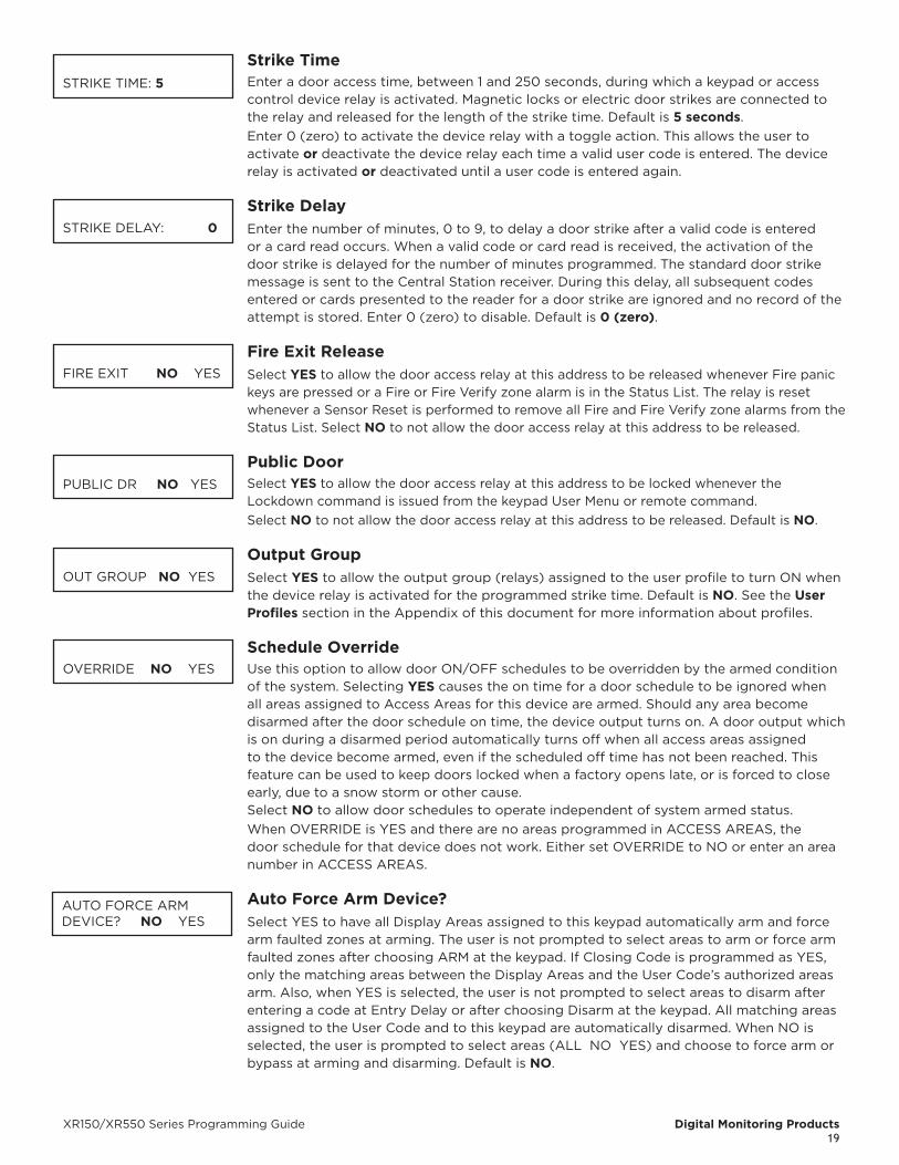
XR150/XR550 Series Programming Guide Digital Monitoring Products19
Strike TimeEnter a door access time, between 1 and 250 seconds, during which a keypad or access control device relay is activated. Magnetic locks or electric door strikes are connected to the relay and released for the length of the strike time. Default is 5 seconds.Enter 0 (zero) to activate the device relay with a toggle action. This allows the user to activate or deactivate the device relay each time a valid user code is entered. The device relay is activated or deactivated until a user code is entered again.
Strike DelayEnter the number of minutes, 0 to 9, to delay a door strike after a valid code is entered or a card read occurs. When a valid code or card read is received, the activation of the door strike is delayed for the number of minutes programmed. The standard door strike message is sent to the Central Station receiver. During this delay, all subsequent codes entered or cards presented to the reader for a door strike are ignored and no record of the attempt is stored. Enter 0 (zero) to disable. Default is 0 (zero).
Fire Exit ReleaseSelect YES to allow the door access relay at this address to be released whenever Fire panic keys are pressed or a Fire or Fire Verify zone alarm is in the Status List. The relay is reset whenever a Sensor Reset is performed to remove all Fire and Fire Verify zone alarms from the Status List. Select NO to not allow the door access relay at this address to be released.
Public DoorSelect YES to allow the door access relay at this address to be locked whenever the Lockdown command is issued from the keypad User Menu or remote command. Select NO to not allow the door access relay at this address to be released. Default is NO.
Output GroupSelect YES to allow the output group (relays) assigned to the user profile to turn ON when the device relay is activated for the programmed strike time. Default is NO. See the User Profiles section in the Appendix of this document for more information about profiles.
Schedule OverrideUse this option to allow door ON/OFF schedules to be overridden by the armed condition of the system. Selecting YES causes the on time for a door schedule to be ignored when all areas assigned to Access Areas for this device are armed. Should any area become disarmed after the door schedule on time, the device output turns on. A door output which is on during a disarmed period automatically turns off when all access areas assigned to the device become armed, even if the scheduled off time has not been reached. This feature can be used to keep doors locked when a factory opens late, or is forced to close early, due to a snow storm or other cause. Select NO to allow door schedules to operate independent of system armed status.When OVERRIDE is YES and there are no areas programmed in ACCESS AREAS, the door schedule for that device does not work. Either set OVERRIDE to NO or enter an area number in ACCESS AREAS.
Auto Force Arm Device? Select YES to have all Display Areas assigned to this keypad automatically arm and force
arm faulted zones at arming. The user is not prompted to select areas to arm or force arm faulted zones after choosing ARM at the keypad. If Closing Code is programmed as YES, only the matching areas between the Display Areas and the User Code’s authorized areas arm. Also, when YES is selected, the user is not prompted to select areas to disarm after entering a code at Entry Delay or after choosing Disarm at the keypad. All matching areas assigned to the User Code and to this keypad are automatically disarmed. When NO is selected, the user is prompted to select areas (ALL NO YES) and choose to force arm or bypass at arming and disarming. Default is NO.
STRIKE TIME: 5
STRIKE DELAY: 0
FIRE EXIT NO YES
PUBLIC DR NO YES
OUT GROUP NO YES
OVERRIDE NO YES
AUTO FORCE ARMDEVICE? NO YES

Digital Monitoring Products XR150/XR550 Series Programming Guide20
Door Real-Time Status? Select YES to have real-time door status messages sent to the PC Log, Entré, and Dealer
Admin accounts that are reporting for this device. Messages are sent anytime the panel turns the door relay on or off. Default is NO.
Send Door Forced Message? Select YES to have the panel send a real-time door status message of Forced Open (FO)
to PC Log reporting and Entré reporting when the door relay is off, but the door zone has transitioned from its normal state. Default is NO.
Program 734/734N OptionsSelect YES to program a 734 or a 734N/734N-POE Wiegand Interface Module. The options displayed for a 734 or 734N are the same.
To program the 734, the Device Type must be set to DOOR and the Device Communication Type must be set to KPD-BUS or AX-BUS.
To program the 734N/734N-POE, the Device Type must be set to DOOR and the Device Communication Type must be set to NETWORK.
Activate Zone 2 bypass Select YES to activate the Bypass option.
Selecting NO allows standard zone operation on Zone 2 and displays the ACTIVATE ZONE 3 REX option. Default setting is NO.If the door being released by the 734/734N/734N-POE module is protected (contact installed), you can provide a programmable Bypass entry/exit timer by connecting its contact wiring to the 734/734N/734N-POE module Zone 2. When the on-board Form C relay activates and the user opens the door connected to Zone 2, the zone is bypassed for the number of seconds programmed in ZONE 2 BYPASS TIME allowing the user to enter/exit.If Zone 2 does not restore (door closed) within the programmed bypass time, the 734/734N/734N-POE piezo pulses during the last ten seconds. If Zone 2 restores prior to the end of the programmed time, the piezo silences. If the zone does not restore before the programmed time, the 734/734N/734N-POE ends the bypass and indicates the open or short zone condition to the panel.
Zone 2 bypass TimeEnter the number of Bypass seconds to elapse before the Bypass timer expires. Range is from 20 to 250 seconds. Press any select key or area to enter the number of seconds. If the door remains open when the timer expires a zone open/short is sent to the panel for Zone 2. The default is 40 seconds.
Relock on Zone 2 Change?Select NO to leave the relay on for the door access time when Zone 2 restores. Select YES to turn the 734/734N/734N-POE relay off and relocks the door when Zone 2 changes state. The default is NO.
Activate Zone 3 Request to ExitSelecting YES activates the Zone 3 Request to Exit (REX) option.Selecting NO allows standard zone operation on Zone 3 and displays the ACTIVATE ONBOARD SPEAKER option. Default setting is NO.Optionally connect a PIR (or other motion sensing device) or a mechanical switch to Zone 3 to provide REX capability to the system. When Zone 3 shorts, the on-board Form C relay activates for the programmed number of seconds. During this time, the user can open the protected door to start the programmed Bypass entry/exit timer. After the programmed number of seconds, the relay restores the door to its locked state.
The 734/734N/734N-POE module provides a bypass-only option for REX on Zone 3. When Zone 3 opens from a normal state, only a bypass occurs: the on-board relay does not activate. This bypass-only option uses two methods of REX. The first REX device provides
DOOR REAL-TIMESTATUS? NO YES
SEND DOOR FORCEDMESSAGE? NO YES
PROGRAM 734 OPTIONS? NO YES
ACTIVATE ZONE 2 BYPASS? NO YES
ZONE 2 BYPASSTIME: 40
RELOCK ON ZONE 2 CHANGE? NO YES
ACTIVATE ZONE 3REX? NO YES

XR150/XR550 Series Programming Guide Digital Monitoring Products21
the programmed Bypass entry/exit timer. The second REX device, or manual device such as a door knob, unlocks the door.An example of the bypass-only configuration is a door to an office that is locked 24 hours a day. Users pass a REX motion detector positioned by the door to begin the programmed exit timer. Within the programmed number of seconds the user must then manually activate a second device, such as a REX device or manual door knob, to unlock the door. If the door is opened after the programmed number of seconds, the zone goes into alarm.
Zone 3 REX Strike TimeEnter the number of REX seconds to elapse. Range is from 5 to 250 seconds. Press any select key or area to enter the number of seconds. The default is 5 seconds.
Activate Onboard SpeakerSelect YES to enable the onboard piezo speaker for local annunciation. Select NO to turn the piezo off for all operations. This does not affect remote annunciator open collector (RA) operation. The default is NO.
Card Options Select DMP to allow only the DMP card format for access. The menu advances to REQUIRE
SITE CODE.Select CUSTOM to disable DMP format and program slots 1-8 as needed. The menu advances to FORMAT NO. The format that is programmed into slot 1 is the default format. In the event that a card with an unrecognized format is programmed when adding a credential, that card will be read in the format that is programmed in slot 1. To restrict card reads to specific formats, only program slots 2-8.
Select ANY to allow all Wiegand card reads to activate the door strike relay. The relay is activated for the length of time programmed in ZN 3 REX TIME. No user code information is sent to the panel. The menu advances to NO COMM WITH PNL.
Require Site Code (If Card Format is Set to DMP)Press the select key or area under YES to use a site code.
In addition to User Code verification, door access is only granted when any one site code programmed at the SITE CODE ENTRY option matches the site code received in the Wiegand string.
No Communication with PanelThis option defines the relay action when communication with the panel has not occurred for approximately ten seconds. Press any select key or area to display relay action options. Press the Back Arrow key to return to the NO OF USER CODE DIGITS:.
Choose the action required:Press the first select key or area to choose OFF [Default] (Relay Always Off) — The relay does not turn on when any Wiegand string is received. Off does not affect any REX operation.
Press the second select key or area to choose SITE (Accept Site Code) — Door access is granted when the Wiegand site code string received matches any site code programmed at SITE CODE ENTRY. For details refer back to the REQUIRE SITE CODE option.
Press the third select key or area to choose ANY (Any Wiegand Read) — Door access is granted when any Wiegand string is received.
Press the fourth select key or area to choose ON (Relay Always On) — The relay is always on.
Press CMD to display the next action.
Press the first select key or area to choose LAST (Keep Last State) — The relay remains in the same state and does not change when communication is lost.After choosing the action, the NO COMM WITH PNL option and the newly defined action display. Programming is now complete. Press CMD to display DEVICE NO.
ZN 3 REX STRIKE TIME: 5
ACTIVATE ONBOARDSPEAKER? NO YES
CARD OPTIONSDMP CUSTOM ANY
REQUIRE SITECODE: NO YES
NO COMM WITH PNLOFF SITE ANY ON
NO COMM WITH PNLOFF
NO COMM WITH PNL SITE
NO COMM WITH PNL ANY
NO COMM WITH PNL ON
NO COMM WITH PNLLAST
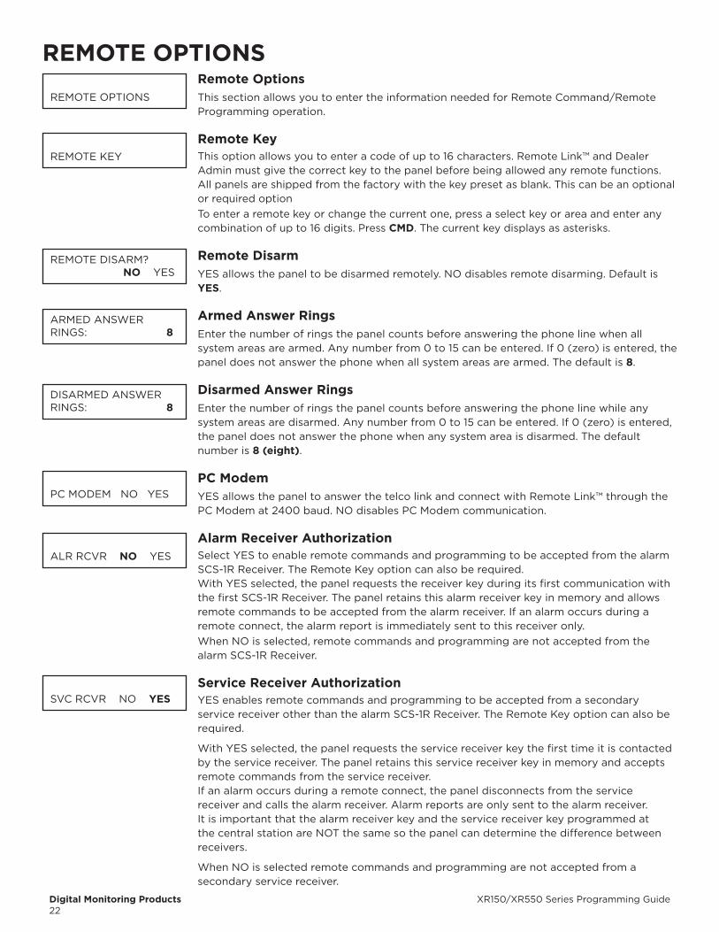
Digital Monitoring Products XR150/XR550 Series Programming Guide22
REMOTE OPTIONSRemote OptionsThis section allows you to enter the information needed for Remote Command/Remote Programming operation.
Remote KeyThis option allows you to enter a code of up to 16 characters. Remote Link™ and Dealer Admin must give the correct key to the panel before being allowed any remote functions. All panels are shipped from the factory with the key preset as blank. This can be an optional or required option To enter a remote key or change the current one, press a select key or area and enter any combination of up to 16 digits. Press CMD. The current key displays as asterisks.
Remote DisarmYES allows the panel to be disarmed remotely. NO disables remote disarming. Default is YES.
Armed Answer RingsEnter the number of rings the panel counts before answering the phone line when all system areas are armed. Any number from 0 to 15 can be entered. If 0 (zero) is entered, the panel does not answer the phone when all system areas are armed. The default is 8.
Disarmed Answer RingsEnter the number of rings the panel counts before answering the phone line while any system areas are disarmed. Any number from 0 to 15 can be entered. If 0 (zero) is entered, the panel does not answer the phone when any system area is disarmed. The default number is 8 (eight).
PC ModemYES allows the panel to answer the telco link and connect with Remote Link™ through the PC Modem at 2400 baud. NO disables PC Modem communication.
Alarm Receiver AuthorizationSelect YES to enable remote commands and programming to be accepted from the alarm SCS-1R Receiver. The Remote Key option can also be required.With YES selected, the panel requests the receiver key during its first communication with the first SCS-1R Receiver. The panel retains this alarm receiver key in memory and allows remote commands to be accepted from the alarm receiver. If an alarm occurs during a remote connect, the alarm report is immediately sent to this receiver only.When NO is selected, remote commands and programming are not accepted from the alarm SCS-1R Receiver.
Service Receiver AuthorizationYES enables remote commands and programming to be accepted from a secondary service receiver other than the alarm SCS-1R Receiver. The Remote Key option can also be required.
With YES selected, the panel requests the service receiver key the first time it is contacted by the service receiver. The panel retains this service receiver key in memory and accepts remote commands from the service receiver.If an alarm occurs during a remote connect, the panel disconnects from the service receiver and calls the alarm receiver. Alarm reports are only sent to the alarm receiver. It is important that the alarm receiver key and the service receiver key programmed at the central station are NOT the same so the panel can determine the difference between receivers.
When NO is selected remote commands and programming are not accepted from a secondary service receiver.
REMOTE OPTIONS
REMOTE KEY
REMOTE DISARM? NO YES
ARMED ANSWERRINGS: 8
DISARMED ANSWERRINGS: 8
PC MODEM NO YES
ALR RCVR NO YES
SVC RCVR NO YES
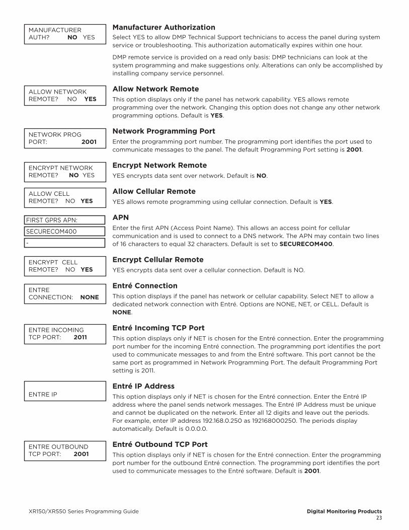
XR150/XR550 Series Programming Guide Digital Monitoring Products23
Manufacturer AuthorizationSelect YES to allow DMP Technical Support technicians to access the panel during system service or troubleshooting. This authorization automatically expires within one hour.
DMP remote service is provided on a read only basis: DMP technicians can look at the system programming and make suggestions only. Alterations can only be accomplished by installing company service personnel.
Allow Network RemoteThis option displays only if the panel has network capability. YES allows remote programming over the network. Changing this option does not change any other network programming options. Default is YES.
Network Programming PortEnter the programming port number. The programming port identifies the port used to communicate messages to the panel. The default Programming Port setting is 2001.
Encrypt Network RemoteYES encrypts data sent over network. Default is NO.
Allow Cellular RemoteYES allows remote programming using cellular connection. Default is YES.
APNEnter the first APN (Access Point Name). This allows an access point for cellular communication and is used to connect to a DNS network. The APN may contain two lines of 16 characters to equal 32 characters. Default is set to SECURECOM400.
Encrypt Cellular RemoteYES encrypts data sent over a cellular connection. Default is NO.
Entré ConnectionThis option displays if the panel has network or cellular capability. Select NET to allow a dedicated network connection with Entré. Options are NONE, NET, or CELL. Default is NONE.
Entré Incoming TCP PortThis option displays only if NET is chosen for the Entré connection. Enter the programming port number for the incoming Entré connection. The programming port identifies the port used to communicate messages to and from the Entré software. This port cannot be the same port as programmed in Network Programming Port. The default Programming Port setting is 2011.
Entré IP Address This option displays only if NET is chosen for the Entré connection. Enter the Entré IP address where the panel sends network messages. The Entré IP Address must be unique and cannot be duplicated on the network. Enter all 12 digits and leave out the periods. For example, enter IP address 192.168.0.250 as 192168000250. The periods display automatically. Default is 0.0.0.0.
Entré Outbound TCP PortThis option displays only if NET is chosen for the Entré connection. Enter the programming port number for the outbound Entré connection. The programming port identifies the port used to communicate messages to the Entré software. Default is 2001.
MANUFACTURERAUTH? NO YES
ALLOW NETWORK REMOTE? NO YES
NETWORK PROGPORT: 2001
ENCRYPT NETWORK REMOTE? NO YES
ALLOW CELLREMOTE? NO YES
SECURECOM400
-
FIRST GPRS APN:
ENCRYPT CELLREMOTE? NO YES
ENTRECONNECTION: NONE
ENTRE INCOMINGTCP PORT: 2011
ENTRE IP
ENTRE OUTBOUNDTCP PORT: 2001
Digital Monitoring Products XR150/XR550 Series Programming Guide24
Entré backup ConnectionThis option displays if NET or CEL is chosen for the Entré connection. Enter the backup address where the panel sends network messages if the first Entré connection fails. The Entré connection must be unique and cannot be duplicated on the network. If the backup connection is NET, enter all 12 digits and leave out the periods. The periods display automatically. Default is 0.0.0.0.
Entré backup TCP PortThis option displays only if NET or CELL is chosen for the Entré connection. Enter the backup programming port number for the outbound Entré connection in case the connection to the primary IP fails. Default is 2001.
Entré ReportsThis option displays only if NET is chosen for the Entré connection. Choose which types of system reports are sent to Entré. Press CMD to view all of the Entré report options. Choose YES to enable arming/disarming, zone, user code, door access, or supervisory message reports. All Entré reports default to YES.
Arm and Disarm ReportsSends arming, disarming and Late to Close events. Includes the area number, name and action, the user number and name, and the time and date.
Zone ReportsSends changes in the status of active zones. Includes the zone number, name, type, the action (alarm, trouble, bypass, etc.), user number (if applicable), and area name. If performing a Walk Test, Zone Verify and Zone Fail messages are sent for each zone.
User Command ReportsSends user code changes, schedule changes, and door access denied events.
Door Access ReportsSends door access activity: door number, user number and name, and time and date.
Supervisory ReportsSends system monitor reports, such as AC and battery, and system event reports. Supervisory Reports also sends the following reports:• Abort • Exit Error • Ambush• System Recently Armed • Alarm Bell Silenced • Unauthorized Entry• Late to Close*
* Only sent as a Supervisory Report if Area Schedules is not enabled, Closing Check is enabled, and an opening/closing schedule has been programmed.To send these reports to the PC Log, you must enable SUPV MSG.
Video ReportsEnabling this feature will allow the panel to send video system reports to Entré when an OpenEye® event message has been received from a camera.
Entré Checkin Select the rate at which check-in messages are sent over the Entré connection. Select 0
(zero) to disable check in messages. Range is 0, 3-240 minutes. Default is 0.
Entré Passphrase To enable encryption enter an 8 to 16-character Passphrase using alphanumeric characters.
If you leave the Passphrase blank, the panel communicates with Entré, but the data is not encrypted. The Passphrase is bLANK by default.
ENTRE BACKUPNONE NET CEL
ENTRE BACKUP TCPPORT: 2001
ENTRE REPORTS000.000.000.000
ARM/DIS NO YES
ZONE: NO YES
USER CMDS NO YES
DOOR ACS: NO YES
SUPV MSG: NO YES
VIDEO: NO YES
ENTRE CHECKINMINUTES: 0
ENTRE PASSPHRASE-

XR150/XR550 Series Programming Guide Digital Monitoring Products25
Integrator ConnectionThis option displays if the panel has network or cellular capability. Select NET to allow a dedicated network connection with the integrator. Options are NONE, NET, or CELL. Default is NONE.
Integrator Incoming TCP Port This option displays only if NET is chosen for the integrator connection. Enter the
programming port number for the incoming connection. The programming port identifies the port used to communicate messages to and from the integrator software. This port cannot be the same port as programmed in Network Programming Port. The default Programming Port setting is 8011.
Integrator IP Address This option displays only if NET is chosen for the integrator connection. Enter the integrator IP address where the panel sends network messages. The integrator IP Address must be unique and cannot be duplicated on the network. The periods display automatically. Default is 0.0.0.0.
Integrator Outbound TCP Port This option displays only if NET is chosen for the integrator connection. Enter the
programming port number for the outbound connection. The programming port identifies the port used to communicate messages to the integrator software. Default is 8001.
Integrator backup ConnectionThis option displays if NET or CELL is chosen for the integrator connection. Enter the backup address where the panel sends network messages if the first integrator connection fails. The connection must be unique and cannot be duplicated on the network. If the backup connection is NET, enter all 12 digits and leave out the periods. For example, enter IP address 192.168.0.250 as 192168000250. The periods display automatically. Default is 0.0.0.0.
Integrator backup TCP Port This option displays only if NET is chosen for the integrator connection. Enter the backup
programming port number for the outbound connection in case the connection to the primary IP fails. Default is 8001.
Integrator Reports This option displays only if NET is chosen for the integrator connection. Choose which
types of system reports are sent to the integrator. Press CMD to view all of the integrator report options. Choose YES to enable arming/disarming, zone, user code, door access, or supervisory message reports. All reports default to YES.
Arm and Disarm ReportsSends arming, disarming and Late to Close events. Includes the area number, name and action, the user number and name, and the time and date.
Zone ReportsSends changes in the status of active zones. Includes the zone number, name, type, the action (alarm, trouble, bypass, etc.), user number (if applicable), and area name. If performing a Walk Test, Zone Verify and Zone Fail messages are sent for each zone.
User Command ReportsSends user code changes, schedule changes, and door access denied events.
Door Access ReportsSends door access activity: door number, user number and name, and time and date.
INTEGRATORCONNECTION: NONE
INTGRTR INCOMINGTCP PORT: 8011
INTEGRATOR IP000.000.000.000
INTGRTR OUTBOUNDTCP PORT: 8001
INTGRTR BACKUP IPNONE NET CELL
INTGRTR BKUP TCPPORT: 8001
INTGRTR REPORTS
ARM/DIS: NO YES
ZONE: NO YES
USR CMDS: NO YES
DOOR ACS: NO YES

Digital Monitoring Products XR150/XR550 Series Programming Guide26
Supervisory ReportsSends system monitor reports, such as AC and battery, and system event reports. Supervisory Reports also sends the following reports:
• Abort • Exit Error • Ambush• System Recently Armed • Alarm Bell Silenced • Unauthorized Entry• Late to Close*
* Only sent as a Supervisory Report if Area Schedules is not enabled, Closing Check is enabled, and an opening/closing schedule has been programmed.To send these reports to the PC Log, you must enable SUPV MSG.
Integrator Passphrase To enable encryption enter an 8 to 16-character Passphrase using alphanumeric characters.
If you leave the Passphrase blank, the panel communicates with the integrator, but the data is not encrypted. The Passphrase is blank by default.
Send Local ChangesThis option allows the panel to automatically update Remote Link™ at the central station with any changes made to the panel.
Select NET or DD to send local programming changes or User Menu changes to user codes, user profiles, schedules, or holiday dates to Remote Link™ after exiting the programming or User Menu. If NET is selected, changes are sent using Network. If DD is selected, changes are sent using Dialer. Default is NO to disable this feature.
Remote Change IPThis option displays when NET is selected for Send Local Changes. Enter the IP address containing up to 12 digits. The Net IP Address must be unique and cannot be duplicated on the network. Enter all 12 digits and leave out the periods. Default is 0.0.0.0.
Remote Change PortThis option displays when NET is selected for Send Local Changes. Enter the Port number. Valid numbers are from 0 to 65535. Default is 2002.
Remote Telephone NumberThis option displays when DD is selected for Send Local Changes. Press CMD to enter the phone number the panel dials when sending programming changes. After entering a phone number, the panel sends any panel changes to Remote Link™.The phone number can have two lines of 16 characters each to equal 32. Enter a P to program a two second pause in the dialing sequence. The P character counts as part of the 32 allowable characters. Enter *70P as the string first characters to cancel call waiting. Dial tone detect is an automatic panel function.
App KeyEnter the 8-digit App Key obtained in your Dealer Settings tab at dealer.securecomwireless.com.This option is a security feature of the Virtual Keypad iPhone/Android App used only when your Dealer Settings at dealer.securecomwireless.com have EASYconnect set as the Communication Type.This communication option is only available for panels with onboard network and is used to eliminate the need for a static IP address programmed in Network Options. To enter a new App Key, press any select key or area and enter any combination of 8 digits. Press CMD.
SUPV MSG: NO YES
INTGRTR PASSPHRASE-
SEND LOCALCHANGES? NO
SEND LOCAL
NO NET DD
REMOTE CHANGE IP000.000.000.000
REMOTE CHANGEPORT: 2002
REMOTE PHONE NO.
-
-
APP KEY:
XR150/XR550 Series Programming Guide Digital Monitoring Products27
SYSTEM REPORTSSystem ReportsSelect specific system reports the panel sends to the receiver.
Abort ReportYES allows the panel to send an alarm abort report to the receiver any time an area is disarmed during Transmit Delay before an alarm report is sent and the Bell Cutoff Time has not expired. After disarming an area, if any other area remains armed and has zone(s) in alarm, the alarm abort report is not sent. Abort Reports are not sent for Fire, Fire Verify, or Supervisory type zones.
Restoral ReportsThis option allows you to control when and if a zone restoral report is sent to the central station receiver. Press any select key or area to display the following options:
NO - Disables the zone restoral report option. Zones continue to operate normally but do not send restoral reports to the receiver.YES - Enables the zone restoral report option. Zone restorals are sent whenever a zone restores from a trouble or alarm condition.DISARM - Causes the panel to send restoral reports for a non-24-hour zone whenever a zone that has restored from a trouble or alarm condition is disarmed. All 24-hour zones send restoral reports as they restore.
bypass ReportsYES allows the panel to send all zone bypasses, resets, and force arm reports to the receiver. The bypass report includes the zone number, zone name, and the user name and number of the individual operating the system. Reports are only sent if O/C User in Communications is set YES for Receiver 1 or Receiver 2.
Schedule Change ReportsYES allows the panel to send all schedule changes to the receiver. The report includes the day, opening time, closing time, extend schedule time, and the user name and number of the individual making the change.
Code Change ReportsYES allows the panel to send all code additions, changes, and deletions to the receiver. The code change report includes the user name and number added or deleted and the user name and number of the individual making the change. Reports are only sent if O/C User in Communications is set YES for Receiver 1 or Receiver 2. The default setting is YES.
Access KeypadsSelect the keypad addresses (1 through 16) that send door access reports to the receiver. Enter the keypad number using the digit keys. An asterisk next to the number indicates that the keypad is selected. Press CMD to display the next set of keypads.A report is sent with each door access made from the selected keypads. Keypads at addresses not selected still operate the door relay but do not send access reports. The report includes the user number, user name, keypad address, and device name.
AmbushYES allows an ambush report to be sent anytime user code number 1 is entered at a keypad. NO disables the ambush report and allows user number 1 to operate the same as all other codes.
SYSTEM REPORTS
ABORT NO YES
RESTORAL: YES
NO YES DISARM
BYPASS NO YES
SCHD CHG NO YES
CODE CHG NO YES
ACCESS KEYPADS
AMBUSH NO YES
Digital Monitoring Products XR150/XR550 Series Programming Guide28
Late To OpenEnter 1-240 as the number of minutes to elapse that the system may remain armed after the opening time of a schedule without sending a Late To Open message. If the system continues to be armed after the Late to Open minutes expire, a Late To Open message is sent to the central station. Default is 0, which disables the Late To Open option.
Early To CloseEnter 1-240 as the number of minutes that the system can be armed prior to the scheduled closing time. If the system is armed prior to the Early to Close minutes, an Early To Close message is sent to the central station. Default is 0, which disables the Early to Close option.
Video ReportsEnabling this feature will allow the panel to send video system reports when an OpenEye event message has been received from a camera.
LATE TO OPEN MINUTES: 0
EARLY TO CLOSEMINUTES: 0
VIDEO: NO YES
XR150/XR550 Series Programming Guide Digital Monitoring Products29
SYSTEM OPTIONSSystem OptionsThis section allows you to select system-wide parameters.
SystemThis option allows you to program how the areas operate for arming and disarming. The system types are:
AREA - All 32 areas can be programmed and operated independently.
ALL/PERIMETER - Area 1 is the Perimeter and Area 2 is the Interior.
HOME/SLEEP/AWAY - Area 1 is the Perimeter, Area 2 is the Interior, and Area 3 is the Bedrooms. With the HOME/SLEEP/AWAY option, the user can:
1. Select HOME to arm just the perimeter.
2. Select SLEEP to arm the perimeter and interior (non bedroom areas).
3. Select AWAY to arm all three areas.
A Home/Sleep/Away system can be configured to use all three areas or only use the Home and Away areas.
HOME/SLEEP/AWAY WITH GUEST- This allows the alarm system to be divided into a main house HOME/SLEEP/AWAY system and two other guest houses that also are set up as HOME/SLEEP/AWAY systems.Areas 1, 2, and 3 are the Perimeter, Interior, and Bedrooms for the Main house system. Areas 4, 5, and 6 are the Perimeter, Interior, and Bedrooms for the Guest 1 house system. Areas 7, 8, and 9 are the Perimeter, Interior, and Bedrooms for the Guest 2 house system. These areas are automatically assigned per system and cannot be changed. See Display Areas in Device Setup to assign keypads to a system. Zones are assigned to a system by assigning the system’s area numbers to the zone in Zone Information programming.When either All/Perimeter or Home/Sleep/Away is selected, the area names are automatically assigned and cannot be modified.Areas 3-32 in an All/Perimeter system, areas 4-32 in a Home/Sleep/Away system, and areas 9-32 in a Home/Sleep/Away with Guest system are not available for use and are initialized.
Instant ArmingWhen YES is selected, the arming keypad displays INSTANT for selection during the exit countdown delay when arming fewer than all areas of the system. At the time instant arming is selected, any entry and exit delays programmed for the areas being armed are ignored. The entry delay for previously armed areas is not affected by instant arming. When NO is selected, INSTANT does not display during arming. Default is NO for an Area System, and YES for an All/Perimeter or Home/Sleep/Away system.
Closing WaitWhen YES is selected, the keypad displays ONE MOMENT... while waiting for an acknowledgement from the receiver before arming the selected area(s) and performing a Bell Test (if selected). Exit delays begin after the Closing Wait. Opening/Closing reports must be YES to enable Closing Wait.
Entry Delay 1Enter the Entry Delay time for all Exit type zones programmed to use Entry Delay 1. When an armed Exit type zone is faulted, the keypad prewarn tone begins sounding. All keypads programmed to prewarn for that zone display ENTER CODE:- and the name of the zone causing the entry delay. Entry Delay times can be from 30 to 250 seconds. Repeat the above for each entry delay being used in the system. For UL Installations, the combined Transmit Delay (Abort Window) and Entry Delay must not exceed one (1) minute.
SYSTEM OPTIONS
SYSTEM: AREA
AREA A/P H/A GST
INST ARM NO YES
CLS WAIT NO YES
ENTRY DLY 2: 60
ENTRY DLY 3: 90
ENTRY DLY 1: 30
ENTRY DLY 4: 120

Digital Monitoring Products XR150/XR550 Series Programming Guide30
Cross Zone TimeEnter the time allowed between zone faults. When zones are cross zoned, the same zone or a second cross zoned zone must fault within this time in order for an alarm report for both zones to be sent to the receiver. If the cross zone time expires without the second zone faulting, only a zone fault from the first zone is reported. Cross-zone time can be from 4 to 250 seconds. Entering 0 (zero) disables this function. Default is 4. See the Appendix.
Zone Retard DelayEnter the retard time assigned to Fire, Supervisory, Auxiliary 1, Auxiliary 2, Arming, and Panic type zones. The retard delay only functions when the zone is shorted. The zone must remain shorted for the entire length of the Retard Delay before being recognized by the panel. The Zone Retard Delay can be from 1 to 250 seconds. Entering a 0 (zero) disables this function.
Power Fail DelayThis option tracks the duration of an AC power failure. When the AC power is off for the length of the programmed delay time, an AC power failure report is sent to the receiver. The delay time can be from 1 to 15 hours. Entering a 0 (zero) sends the power failure report after a 15-second delay. The default setting is 1.
Swinger bypass TripsEnter the number of times (1-6) a zone can go into an alarm or trouble condition within one hour be fore being auto matically bypassed. Bypassed zones are auto matically reset when the area they are assigned to is disarmed. All 24-hour zones are reset when any area of the system is dis armed. Entering 0 (zero) disables this function. Default is 2. A Bypass Re port is sent to the receiver if Bypass Re ports is YES.
Reset Swinger bypassWhen YES is selected, an auto matically bypassed zone is reset if it remains in a normal condition for one complete hour after being bypassed. A report of the automatic reset is sent to the receiver if Bypass Reports has been se lected as YES. Default is NO.
Zone Activity HoursThis option provides supervision of a person living alone for non-activity. Enter the number of hours, 0 to 9, allowed to elapse without a disarmed zone being tripped before a message is sent to the receiver. Default is 0 (zero).When the system is disarmed, the timer begins to countdown the number of hours programmed. Each time activity occurs, the timer restarts the countdown. Before the countdown time expires, the keypad sounds a tone and PRESS ANY KEY displays to allow the user to restart the activity timer. The duration of the tone is the number of seconds programmed for Entry Delay 2. Select the SUPV/TRBL receiver option in communication programming to send S93 ALARM: User Activity Not Detected, S94 Alert: Activity Check Enabled, and S95 Alert: Activity Check Disabled messages.
CRS ZONE TM: 4
RETARD DELAY: 10
PWR FAIL HRS: 1
SWGRBYPS TRIPS: 2
RST SBYP NO YES
ZN ACTY HRS: 0
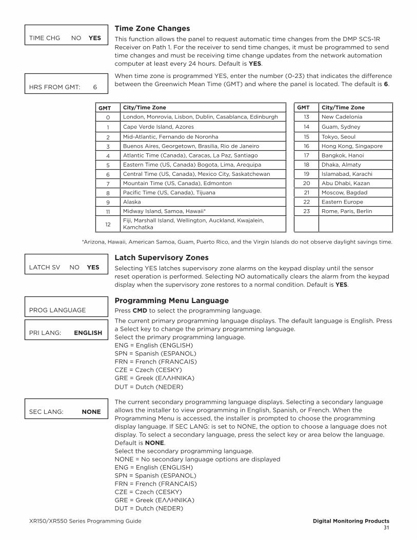
XR150/XR550 Series Programming Guide Digital Monitoring Products31
Time Zone ChangesThis function allows the panel to request automatic time changes from the DMP SCS-1R Receiver on Path 1. For the receiver to send time changes, it must be programmed to send time changes and must be receiving time change updates from the network automation computer at least every 24 hours. Default is YES.
When time zone is programmed YES, enter the number (0-23) that indicates the difference between the Greenwich Mean Time (GMT) and where the panel is located. The default is 6.
GMT City/Time Zone GMT City/Time Zone
0 London, Monrovia, Lisbon, Dublin, Casablanca, Edinburgh 13 New Cadelonia
1 Cape Verde Island, Azores 14 Guam, Sydney
2 Mid-Atlantic, Fernando de Noronha 15 Tokyo, Seoul
3 Buenos Aires, Georgetown, Brasilia, Rio de Janeiro 16 Hong Kong, Singapore
4 Atlantic Time (Canada), Caracas, La Paz, Santiago 17 Bangkok, Hanoi
5 Eastern Time (US, Canada) Bogota, Lima, Arequipa 18 Dhaka, Almaty
6 Central Time (US, Canada), Mexico City, Saskatchewan 19 Islamabad, Karachi
7 Mountain Time (US, Canada), Edmonton 20 Abu Dhabi, Kazan
8 Pacific Time (US, Canada), Tijuana 21 Moscow, Bagdad
9 Alaska 22 Eastern Europe
11 Midway Island, Samoa, Hawaii* 23 Rome, Paris, Berlin
12Fiji, Marshall Island, Wellington, Auckland, Kwajalein, Kamchatka
*Arizona, Hawaii, American Samoa, Guam, Puerto Rico, and the Virgin Islands do not observe daylight savings time.
Latch Supervisory ZonesSelecting YES latches supervisory zone alarms on the keypad display until the sensor reset operation is performed. Selecting NO automatically clears the alarm from the keypad display when the supervisory zone restores to a normal condition. Default is YES.
Programming Menu LanguagePress CMD to select the programming language.
The current primary programming language displays. The default language is English. Press a Select key to change the primary programming language.
Select the primary programming language. ENG = English (ENGLISH) SPN = Spanish (ESPANOL) FRN = French (FRANCAIS)
CZE = Czech (CESKY) GRE = Greek (ΕΛΛΗΝΙΚΆ) DUT = Dutch (NEDER)
The current secondary programming language displays. Selecting a secondary language allows the installer to view programming in English, Spanish, or French. When the Programming Menu is accessed, the installer is prompted to choose the programming display language. If SEC LANG: is set to NONE, the option to choose a language does not display. To select a secondary language, press the select key or area below the language. Default is NONE.
Select the secondary programming language. NONE = No secondary language options are displayed ENG = English (ENGLISH) SPN = Spanish (ESPANOL) FRN = French (FRANCAIS)
CZE = Czech (CESKY) GRE = Greek (ΕΛΛΗΝΙΚΆ) DUT = Dutch (NEDER)
TIME CHG NO YES
HRS FROM GMT: 6
LATCH SV NO YES
PROG LANGUAGE
PRI LANG: ENGLISH
SEC LANG: NONE
Digital Monitoring Products XR150/XR550 Series Programming Guide32
User Menu and Status List LanguagePress CMD to select User Language.
The current primary user language displays. The default language is English. Press any select key or area to change the primary User language.
Select the primary user language. ENG = English (ENGLISH) SPN = Spanish (ESPANOL) FRN = French (FRANCAIS)
CZE = Czech (CESKY) GRE = Greek (ΕΛΛΗΝΙΚΆ) DUT = Dutch (NEDER)
The current secondary user language displays. Selecting a secondary user language allows the user to view the User Menu and Status List text in English, Spanish, or French. When the User Menu is accessed, the user is prompted to choose the display language. Status List text displays in the selected language until another language is chosen. If SEC LANG: is set to NONE, the option to choose a language does not display. To select a secondary language, press the select key or area below the language. Default is NONE.
Select the secondary user language. NONE = No secondary language options are displayed ENG = English (ENGLISH) SPN = Spanish (ESPANOL) FRN = French (FRANCAIS)
CZE = Czech (CESKY) GRE = Greek (ΕΛΛΗΝΙΚΆ) DUT = Dutch (NEDER)
bypass LimitEnter the maximum number of zones (0 to 8) that can be bypassed in any single area when that area is being armed at a keypad. If more zones than the limit are in a non-normal state or already bypassed at arming, arming does not occur and Arming Stopped displays. The Bypass limit does not affect auto arming, keyswitch arming, or remote arming. Entering 0 (zero) allows no limit. Default is 0 (zero).
House CodeWhen using a DMP wireless system, enter a house code between 1 and 50. Default is 0 indicating no wireless system is being used. The DMP house code identifies the panel, DMP receiver, and DMP transmitters to each other. The DMP receiver listens for transmissions that have the programmed house code and transmitter serial number. The transmitters may take up to two minutes to learn the new house code and continue operation.
Wireless EncryptionEncryption allows the panel to communicate with encrypted 1100 Series wireless devices. Select ALL to to allow encryption for all the wireless devices programmed into the panel. Select BOTH to allow encryption for selected wireless devices programmed into the panel. Select NONE to don’t allow encryption for wireless devices programmed into the panel. The default is NONE.
Enter PassphraseENTER PASSPHRASE displays if you select ALL or BOTH for wireless encryption. In order for the panel to support encrypted 1100 Series wireless devices, a passphrase must be entered. The passphrase must be an 8-digit hexadecimal number which determines the system’s encryption key.
USER LANGUAGEPRI LANG: ENGLISH
SEC LANG: NONE
BYPASS LIMIT 0
WIRELESSHOUSE CODE: 0
1100 ENCRYPTIONALL BOTH NONE
1100 PASSPHRASE********

XR150/XR550 Series Programming Guide Digital Monitoring Products33
Detect Wireless JammingThis option displays when the House Code entered is for a DMP 1100 Series Wireless system (1-50). When enabled and the wireless receiver detects jamming, a jammed trouble (when disarmed) or jammed alarm (when armed) message displays in the Status List and is sent to the central station receiver. Select YES to enable jamming messages to display in the Status List. Select NO to disable jamming messages. Default is NO.
Trouble Audible AnnunciationThis option allows you to choose when trouble audibles will annunciate from the keypad. Press any top row key to select the keypad buzzer annunciation method for wireless low battery and missing messages. Select ANY to enable annunciation anytime. Select DAY to enable annunciation except during sleeping hours (9 PM to 9 AM). Select MIN (minimum) to annunciate only Fire and Fire Verify zones during daytime hours (9 AM to 9 PM). Default is DAY.
Enable Keypad Panic KeysThis option allows the panic key operation selected at the keypad to send the Panic, Emergency, or Fire message to the central station receiver. Select YES to enable the two-button panic operation to operate. To disable the panic operation, select NO. Default is YES.
Occupied PremisesFor All/Perimeter or Home/Sleep/Away systems, select YES to allow the panel to automatically disarm the interior area(s) when arming all areas and a perimeter zone is not tripped during the exit delay.This False Alarm Reduction feature will keep a user from arming the entire system when they do not exit and remain in the premises. Select NO to disable this feature. Default is YES.With a Home/Sleep/Away with Guest arming system, this feature only applies to the main system.
Enhanced Zone TestSelect YES to allow enhanced zone test operation for Walk Test (8144), Panic Test, and Burglary Zone Test in the User Menu. The default is NO.Enhanced operation allows:• A Verify message to be sent each time a zone is tested. If a zone is tripped multiple
times, a Verify message is sent for each trip. This allows the Central Station to record the number of devices per zone.
• The Verify message for each zone test to be sent at the time the trip occurs instead of at the end of Walk Test.
• The System Test Begin and System Test End Central Station messages indicate the type of zone being tested. The System Test Begin message also includes the user name and number.
Send 16 Character NamesThis option allows central stations to select being sent either the first 16 characters of the name field or the entire programmed name, up to 32 characters, for user name, user profile, zone name, area name, output name, and group name.Select YES to have the first 16 characters of the name field sent to the central station. Select NO to send the exact number of characters entered in the name field from 1 up to the maximum of 32 characters. Default is YES.
Before using names longer than 16 characters, determine whether the Host Automation System of your Central Station can accept 17 to 32 character names. If not, only use 16 character names.
DETECT WIRELESS JAMMING: NO YES
TRBL AUDIBLE: DAY
KEYPAD PANIC KEYSENABLED: NO YES
OCCUPIED PREMISES: NO YES
ENHANCED ZONETEST: NO YES
SEND 16 CHARNAMES: NO YES
Digital Monitoring Products XR150/XR550 Series Programming Guide34
Keypad Armed LEDThis option displays only when using an Area system. Press any top row key to select the operation of the Armed LED on the keypad. Select ALL to require all keypad display areas to be armed before the keypad Armed LED turns on. Select ANY to turn on the keypad Armed LED when any keypad display area is armed. Default is ALL.
Use False Alarm QuestionThis option allows users to investigate a burglary alarm prior to disarming the system and send an Alarm Verified or Alarm Cancelled message to the Central Station.
Select YES to display IS THIS A FALSE ALARM? NO YES when a burglar alarm occurs. Select NO to display CANCEL VERIFY. Default is YES.
When a burglar alarm occurs in an area system and a user code is entered at a keypad Status List, keypads programmed as KPD in Device Setup display IS THIS A FALSE ALARM? NO YES or CANCEL VERIFY. The option is not displayed at devices programmed as DOOR. Selecting NO or Verify sends an alarm message to the Central Station. Selecting YES or CANCEL sends an alarm cancelled message to the Central Station and disarms the areas that the user has the authority to disarm. This display remains on the keypad until a selection is made, the Back Arrow is pressed, or the internal system bell cutoff timer expires.
Allow Own User Code ChangeThis option allows users without user code authority to change their own user code. When YES is selected, the User Code menu displays USER CODE: ***** at the keypad to allow that user to change their own code. If NO is selected, the user cannot change their personal user code. Default is NO.
Panic SupervisionSelect YES to enable a 30 day supervision of the Model 1145-1-B-PSV key fob. Default is NO.This option allows a key fob that is lost or has a dead battery to be identified at the Central Station host automation system as a missing transmitter, without the need to apply a supervision time in zone information programming. A supervision message is automatically sent from the key fob to SCS-VR every four hours, resetting the 30 day countdown timer for that key fob serial number. If the 30 day timer expires for a key fob serial number, SCS-VR will generate a zone missing message to the host automation system.
Weather Zip CodeThis option allows local U.S.A. weather updates to display on the keypad. Enter the zip code of the user at this option. When no number is entered weather conditions are not displayed. Default is 0 (zero).If using a 7800 Series keypad, the current weather conditions and the next day’s forecast display as graphics on the Main Screen. All other DMP keypads display the weather information in the Status List.
EOL SelectionSelect the resistance value in kOhms that the system will expect for end of line resistors. Values can be set at either 1k or 2.2k. This adjusts the voltage threshold used to determine open, short, or normal zone conditions for zones 1-8 on XR Series panels. Default is 1k. Zones 9-10 on XR Series panels are defaulted to 3.3k.
Celsius Temperature OptionThis option determines whether the panel should use Celsius Units for displayed temperatures and for sending temperatures to Z-Wave thermostats. The default is NO.
KEYPAD ARMED LEDANY ALL
USE FALSE ALARM QUESTION NO YES
ALLOW OWN USERCODE CHG? NO YES
PANIC SUPERVISION NO YES
ENTER WEATHER ZIP CODE: 0
EOL VALUE: XXXX
CELSIUS: NO YES
XR150/XR550 Series Programming Guide Digital Monitoring Products35
bELL OPTIONSbell OptionsThis section allows you to program the panel bell output functions.
bell Cutoff TimeEnter the maximum time from 1 to 99 minutes the Bell Output remains on. If the area is disarmed, the cutoff time resets. Enter 0 (zero) to provide continuous bell output. The default is 15 minutes. To support the Cancel Verify feature on an All/Perimeter or Home/Sleep/Away system, set the Bell Cutoff Time to greater than 0.
Automatic bell TestSelect YES to turn on the Bell Output for 2 seconds each time the system is armed from a keypad. This test is delayed until the Closing Wait acknowledge is received (if programmed). If the Closing Wait acknowledge is not received within 90 seconds, the bell test does not occur. Arming performed from an Arming zone or from Remote Link™ does not activate the Bell Test.
bell OutputEnter the output/Favorite number when needed to follow the panel Bell Output operation for all action and off conditions. Enter 0 (zero) to disable.
bell ActionThis section defines the type of Bell Output for zone alarms. Press CMD to display the default Bell Output for each zone type. Press any select key or area and enter S for a Steady Bell Output, P for a Pulsed output, T for a Temporal Code 3 output, 4 for a Temporal Code 4 output, and N for no Bell Output (default). Enable this feature to latch a bell action to a keypad for Panic zones. Trouble conditions do not activate the Bell Output.
Fire bell ActionDefines Bell Action for Fire Type zones. The default is T.
burglary bell ActionDefines Bell Action for Burglary Type zones and Exit Error output. The default is S.
Supervisory bell ActionDefines Bell Action for Supervisory Type zones. The default is N.
Panic bell ActionDefines Bell Action for Panic Type zones. The default is N.
Emergency bell ActionDefines Bell Action for Emergency Type zones. The default is N.
Auxiliary 1 bell ActionDefines Bell Action for Auxiliary 1 Type zones. The default is N.
Auxiliary 2 bell ActionDefines Bell Action for Auxiliary 2 Type zones. The default is N.
Carbon Monoxide (CO)Defines Bell Action for Carbon Monoxide (CO) Type Zones. The default is set at 4.
BELL OPTIONS
BELL CUTOFF: 15
BELL TST NO YES
BELL OUTPUT: 0
BELL ACTION . . . . .
FIRE TYPE: T
BURGLARY TYPE: S
SUPRVSRY TYPE: N
PANIC TYPE: N
EMERGNCY TYPE: N
AUXLRY 1 TYPE: N
AUX 2 TYPE: N
CO TYPE: 4
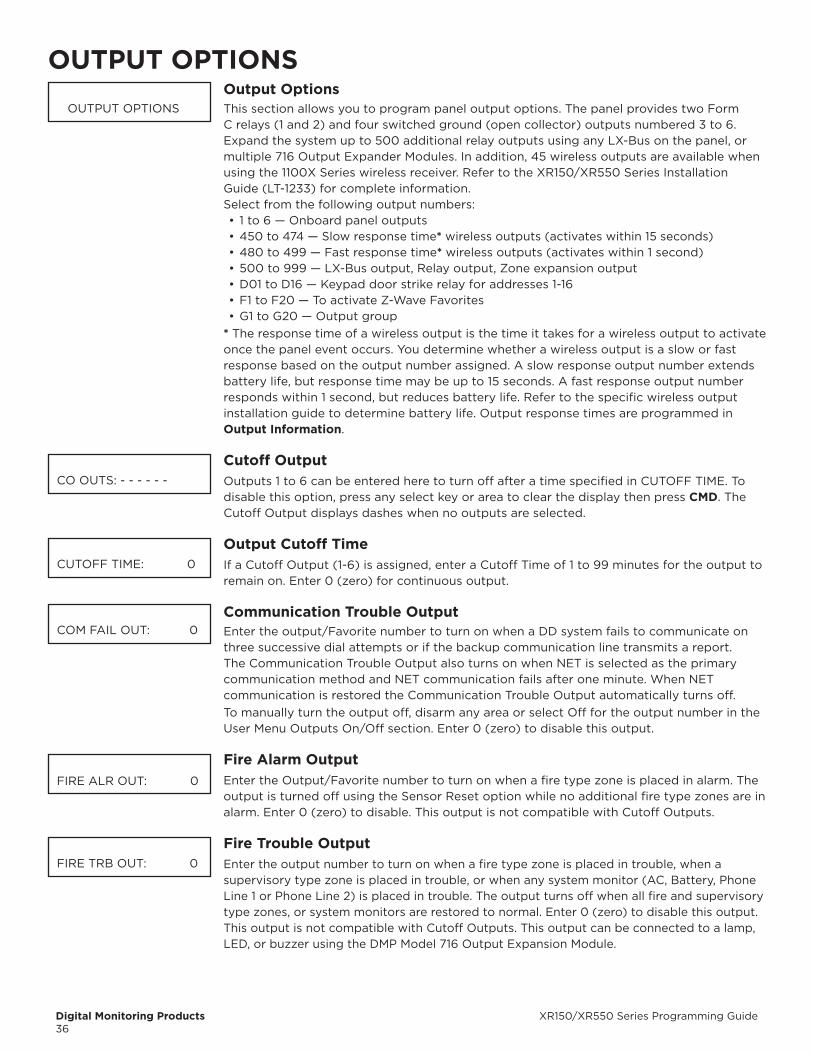
Digital Monitoring Products XR150/XR550 Series Programming Guide36
OUTPUT OPTIONSOutput OptionsThis section allows you to program panel output options. The panel provides two Form C relays (1 and 2) and four switched ground (open collector) outputs numbered 3 to 6. Expand the system up to 500 additional relay outputs using any LX-Bus on the panel, or multiple 716 Output Expander Modules. In addition, 45 wireless outputs are available when using the 1100X Series wireless receiver. Refer to the XR150/XR550 Series Installation Guide (LT-1233) for complete information.Select from the following output numbers:• 1 to 6 — Onboard panel outputs• 450 to 474 — Slow response time* wireless outputs (activates within 15 seconds)• 480 to 499 — Fast response time* wireless outputs (activates within 1 second)• 500 to 999 — LX-Bus output, Relay output, Zone expansion output• D01 to D16 — Keypad door strike relay for addresses 1-16• F1 to F20 — To activate Z-Wave Favorites• G1 to G20 — Output group
* The response time of a wireless output is the time it takes for a wireless output to activate once the panel event occurs. You determine whether a wireless output is a slow or fast response based on the output number assigned. A slow response output number extends battery life, but response time may be up to 15 seconds. A fast response output number responds within 1 second, but reduces battery life. Refer to the specific wireless output installation guide to determine battery life. Output response times are programmed in Output Information.
Cutoff OutputOutputs 1 to 6 can be entered here to turn off after a time specified in CUTOFF TIME. To disable this option, press any select key or area to clear the display then press CMD. The Cutoff Output displays dashes when no outputs are selected.
Output Cutoff TimeIf a Cutoff Output (1-6) is assigned, enter a Cutoff Time of 1 to 99 minutes for the output to remain on. Enter 0 (zero) for continuous output.
Communication Trouble OutputEnter the output/Favorite number to turn on when a DD system fails to communicate on three successive dial attempts or if the backup communication line transmits a report. The Communication Trouble Output also turns on when NET is selected as the primary communication method and NET communication fails after one minute. When NET communication is restored the Communication Trouble Output automatically turns off.To manually turn the output off, disarm any area or select Off for the output number in the User Menu Outputs On/Off section. Enter 0 (zero) to disable this output.
Fire Alarm OutputEnter the Output/Favorite number to turn on when a fire type zone is placed in alarm. The output is turned off using the Sensor Reset option while no additional fire type zones are in alarm. Enter 0 (zero) to disable. This output is not compatible with Cutoff Outputs.
Fire Trouble OutputEnter the output number to turn on when a fire type zone is placed in trouble, when a supervisory type zone is placed in trouble, or when any system monitor (AC, Battery, Phone Line 1 or Phone Line 2) is placed in trouble. The output turns off when all fire and supervisory type zones, or system monitors are restored to normal. Enter 0 (zero) to disable this output. This output is not compatible with Cutoff Outputs. This output can be connected to a lamp, LED, or buzzer using the DMP Model 716 Output Expansion Module.
OUTPUT OPTIONS
CO OUTS: - - - - - -
CUTOFF TIME: 0
COM FAIL OUT: 0
FIRE ALR OUT: 0
FIRE TRB OUT: 0

XR150/XR550 Series Programming Guide Digital Monitoring Products37
Panic Alarm OutputEnter the output/Favorite number to turn on when any Panic type zone is placed in an alarm condition. The output is turned off after all Panic zones are restored from an alarm condition and a Sensor Reset is performed. Enter 0 (zero) to disable.Wireless Outputs• The Panic Alarm is compatible with the Model 1118 Wireless Remote Indicator Light and
the Model 1116 Wireless Relay Output connected to a Model 572 Indicator LED.• When a Panic Alarm occurs, the LED turns on steady for five minutes and then turns off.• When a Panic Test is initiated from the keypad, the LED flashes quickly for five minutes.• For a Panic Alarm, a fast response wireless output number is recommended.
Ambush OutputEnter the output/Favorite number to turn on when an Ambush code is entered at a keypad. The output is turned off using the Sensor Reset option. Enter 0 (zero) to disable.
Entry OutputEnter the output/Favorite number to turn on at the start of the entry delay time. The output turns off when the area is disarmed or the entry delay time expires. Enter 0 (zero) to disable.
begin Exit OutputThis output/Favorite turns on any time an exit delay time starts. The output turns off when the system arms or when the arming has been stopped. Enter 0 (zero) to disable.
End Exit OutputThis output/Favorite turns on any time an exit delay time ends. The output turns off when the system disarms. Enter 0 (zero) to disable.
Ready OutputEnter the output/Favorite number to turn on when all disarmed burglary zones are in a normal state. The output is turned off when any disarmed burglary type zone is in a bad state. Enter 0 (zero) to disable. This output is not compatible with Cutoff Outputs.
Armed OutputThe entered output turns on any time the system is armed. The programming prompt displayed is dependent on the system’s arming type.
For Home/Away systems, only the HOME and AWAY screens display. If a Bedroom area is programmed into the panel, the SLEEP screen also displays. For All/Perimeter systems, the ALL and PERIM screens display. For Area systems, the ARMED OUT screen displays.
All options are defaulted to 0 (zero). The output turns off when the system completely disarms. Enter 0 (zero) to disable this output.
Disarmed OutputThis output/Favorite turns on when all areas of the panel are disarmed. The output turns off when an area is armed.
Telephone Trouble OutputEnter the output/Favorite number to turn on when the phone line monitor on the panel phone line is lost. Enter 0 (zero) to disable this output.
Late To Close OutputEnter the output/Favorite number to turn on at the expiration of a Closing schedule. The output activates simultaneously with the CLOSING TIME! keypad display. The output is turned off when the area is armed, the Closing is extended, or the schedule is changed. Enter 0 (zero) to disable this output.
PANIC ALM OUT: 0
AMBUSH OUT: 0
ENTRY OUT: 0
BEG EXIT OUT: 0
END EXIT OUT: 0
READY OUT: 0
ARMED HOME: 0
ARMED SLEEP: 0
ARMED ALL: 0
ARMED PERIM: 0
ARMED AWAY: 0
ARMED OUT: 0
DISARMED OUT: 0
PH TRBL OUT: 0
LATE CLS OUT: 0
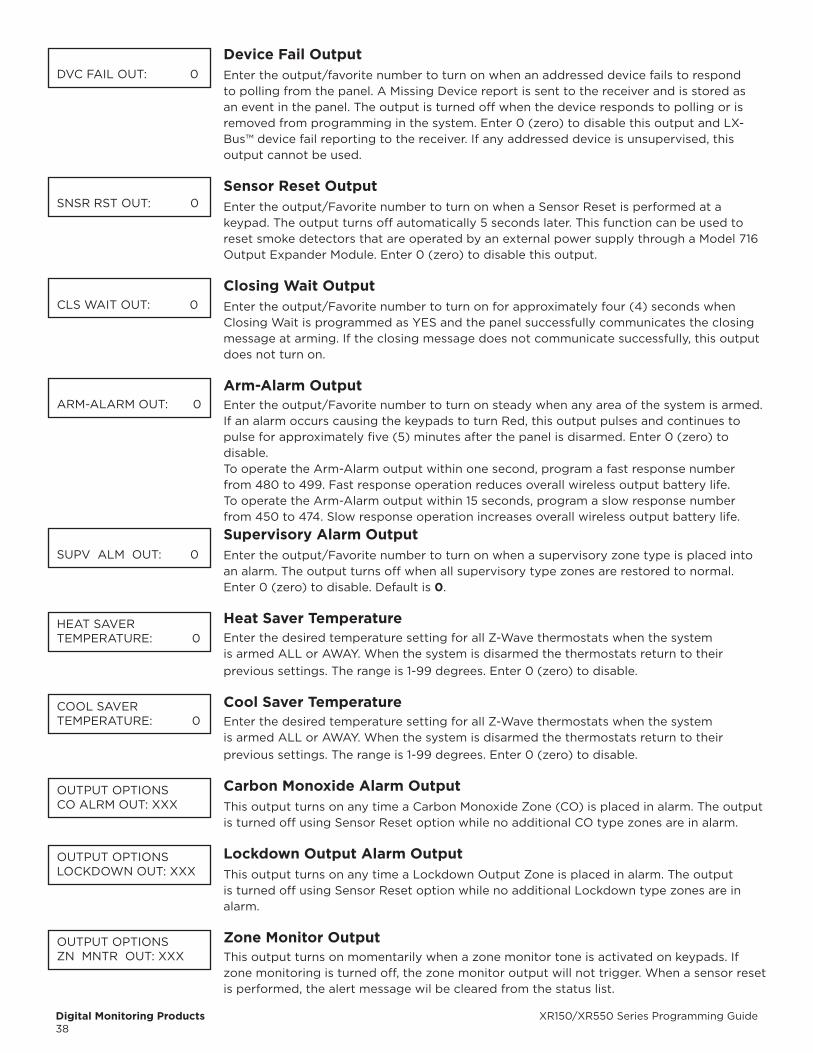
Digital Monitoring Products XR150/XR550 Series Programming Guide38
Device Fail OutputEnter the output/favorite number to turn on when an addressed device fails to respond to polling from the panel. A Missing Device report is sent to the receiver and is stored as an event in the panel. The output is turned off when the device responds to polling or is removed from programming in the system. Enter 0 (zero) to disable this output and LX-Bus™ device fail reporting to the receiver. If any addressed device is unsupervised, this output cannot be used.
Sensor Reset OutputEnter the output/Favorite number to turn on when a Sensor Reset is performed at a keypad. The output turns off automatically 5 seconds later. This function can be used to reset smoke detectors that are operated by an external power supply through a Model 716 Output Expander Module. Enter 0 (zero) to disable this output.
Closing Wait OutputEnter the output/Favorite number to turn on for approximately four (4) seconds when Closing Wait is programmed as YES and the panel successfully communicates the closing message at arming. If the closing message does not communicate successfully, this output does not turn on.
Arm-Alarm OutputEnter the output/Favorite number to turn on steady when any area of the system is armed. If an alarm occurs causing the keypads to turn Red, this output pulses and continues to pulse for approximately five (5) minutes after the panel is disarmed. Enter 0 (zero) to disable.To operate the Arm-Alarm output within one second, program a fast response number from 480 to 499. Fast response operation reduces overall wireless output battery life.To operate the Arm-Alarm output within 15 seconds, program a slow response number from 450 to 474. Slow response operation increases overall wireless output battery life.
Supervisory Alarm OutputEnter the output/Favorite number to turn on when a supervisory zone type is placed into an alarm. The output turns off when all supervisory type zones are restored to normal. Enter 0 (zero) to disable. Default is 0.
Heat Saver TemperatureEnter the desired temperature setting for all Z-Wave thermostats when the systemis armed ALL or AWAY. When the system is disarmed the thermostats return to theirprevious settings. The range is 1-99 degrees. Enter 0 (zero) to disable.
Cool Saver TemperatureEnter the desired temperature setting for all Z-Wave thermostats when the systemis armed ALL or AWAY. When the system is disarmed the thermostats return to theirprevious settings. The range is 1-99 degrees. Enter 0 (zero) to disable.
Carbon Monoxide Alarm OutputThis output turns on any time a Carbon Monoxide Zone (CO) is placed in alarm. The output is turned off using Sensor Reset option while no additional CO type zones are in alarm.
Lockdown Output Alarm OutputThis output turns on any time a Lockdown Output Zone is placed in alarm. The output is turned off using Sensor Reset option while no additional Lockdown type zones are in alarm.
Zone Monitor OutputThis output turns on momentarily when a zone monitor tone is activated on keypads. If zone monitoring is turned off, the zone monitor output will not trigger. When a sensor reset is performed, the alert message wil be cleared from the status list.
DVC FAIL OUT: 0
SNSR RST OUT: 0
CLS WAIT OUT: 0
ARM-ALARM OUT: 0
SUPV ALM OUT: 0
HEAT SAVERTEMPERATURE: 0
COOL SAVERTEMPERATURE: 0
OUTPUT OPTIONSCO ALRM OUT: XXX
OUTPUT OPTIONSLOCKDOWN OUT: XXX
OUTPUT OPTIONSZN MNTR OUT: XXX

XR150/XR550 Series Programming Guide Digital Monitoring Products39
OUTPUT INFORMATIONOutput NumberEnter an output number. Entry range is 1 to 6, 450 to 474, 480 to 499, 500 to 999.In order for wireless output troubles to display at a keypad, the keypad address must be specified at the Auxiliary 1 Zones option in the Status List programming.
Output NameThis section allows you to define a 32 character alphanumeric name for any output numbers. See the XR150/XR550 Users Guide (LT-1278) Appendix for browser operation.
Output Real-Time StatusSelecting YES allows Real-Time Status reports of a hardwire device, such as Output ON, OFF, PULSE, or TEMPORAL to be sent using PC Log reports. Selecting NO disables Real-Time Status for this output device. Default is NO.
Serial NumberIf a house code is programmed in system options, then this option and the next option only display when the output number entered is for a wireless output. Enter the eight-digit serial number found on the wireless device.Already In Use displays when the serial number is already programmed for another output. The programmed output number displays.
Supervision TimePress any select key or area to select the supervision time required for the wireless output. Press CMD to accept the default time. Default is 240 minutes.Select the required number of minutes. The transmitter must check in at least once during this time or a missing condition is indicated for that zone. Zero (0) indicates an unsupervised transmitter. The 3 minute supervision time is only available if using an 1135 Wireless Siren.When the panel is reset, a receiver is installed or powered down and powered up, or programming is complete, the supervision timer restarts for all wireless outputs.
Trip with Panel bell OptionThis option displays when the wireless device is an 1135 wireless siren. Select YES to have the 1135 wireless siren follow the panel’s bell output cadence for the zone type and bell cutoff time up to 15 minutes. Default is YES.
OUTPUT NUMBER
OUTPUT NAME
OUTPUT REAL-TIMESTATUS NO YES
SERIAL#: XXXXXXXX
ALREADY IN USEOUTPUT NO: XXX
SUPERVSN TIME: 2400 3 60 240
TRIP WITH PANELBELL NO YES
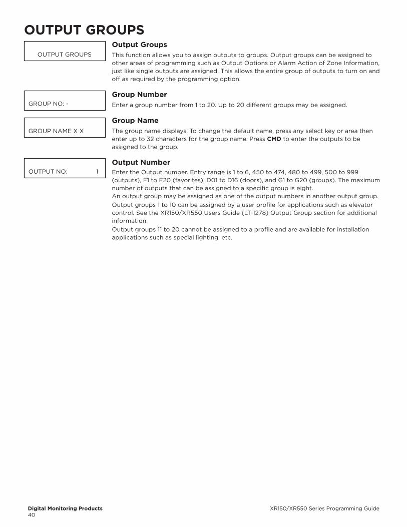
Digital Monitoring Products XR150/XR550 Series Programming Guide40
OUTPUT GROUPSOutput GroupsThis function allows you to assign outputs to groups. Output groups can be assigned to other areas of programming such as Output Options or Alarm Action of Zone Information, just like single outputs are assigned. This allows the entire group of outputs to turn on and off as required by the programming option.
Group NumberEnter a group number from 1 to 20. Up to 20 different groups may be assigned.
Group NameThe group name displays. To change the default name, press any select key or area then enter up to 32 characters for the group name. Press CMD to enter the outputs to be assigned to the group.
Output NumberEnter the Output number. Entry range is 1 to 6, 450 to 474, 480 to 499, 500 to 999 (outputs), F1 to F20 (favorites), D01 to D16 (doors), and G1 to G20 (groups). The maximum number of outputs that can be assigned to a specific group is eight.An output group may be assigned as one of the output numbers in another output group.Output groups 1 to 10 can be assigned by a user profile for applications such as elevator control. See the XR150/XR550 Users Guide (LT-1278) Output Group section for additional information.Output groups 11 to 20 cannot be assigned to a profile and are available for installation applications such as special lighting, etc.
OUTPUT GROUPS
GROUP NO: -
GROUP NAME X X
OUTPUT NO: 1
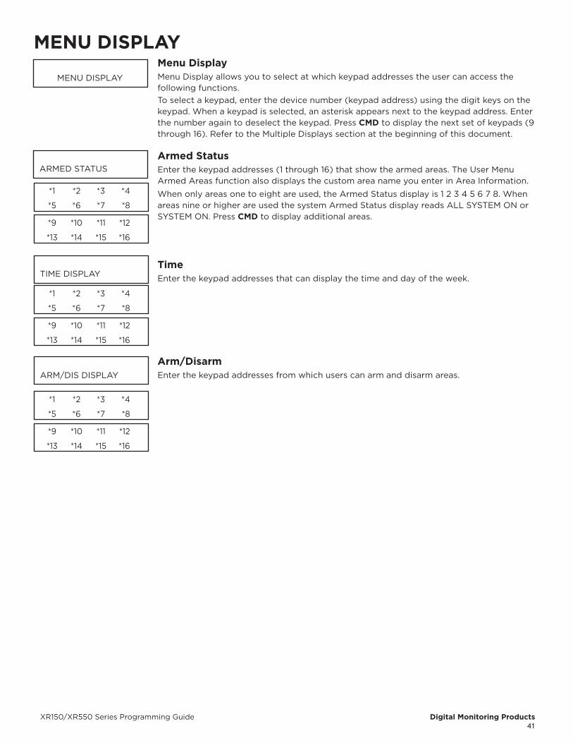
XR150/XR550 Series Programming Guide Digital Monitoring Products41
MENU DISPLAYMenu DisplayMenu Display allows you to select at which keypad addresses the user can access the following functions.To select a keypad, enter the device number (keypad address) using the digit keys on the keypad. When a keypad is selected, an asterisk appears next to the keypad address. Enter the number again to deselect the keypad. Press CMD to display the next set of keypads (9 through 16). Refer to the Multiple Displays section at the beginning of this document.
Armed StatusEnter the keypad addresses (1 through 16) that show the armed areas. The User Menu Armed Areas function also displays the custom area name you enter in Area Information.
When only areas one to eight are used, the Armed Status display is 1 2 3 4 5 6 7 8. When areas nine or higher are used the system Armed Status display reads ALL SYSTEM ON or SYSTEM ON. Press CMD to display additional areas.
TimeEnter the keypad addresses that can display the time and day of the week.
Arm/DisarmEnter the keypad addresses from which users can arm and disarm areas.
MENU DISPLAY
ARMED STATUS
*1 *2 *3 *4
*5 *6 *7 *8
*9 *10 *11 *12
*13 *14 *15 *16
TIME DISPLAY
*1 *2 *3 *4
*5 *6 *7 *8
*9 *10 *11 *12
*13 *14 *15 *16
ARM/DIS DISPLAY
*1 *2 *3 *4
*5 *6 *7 *8
*9 *10 *11 *12
*13 *14 *15 *16
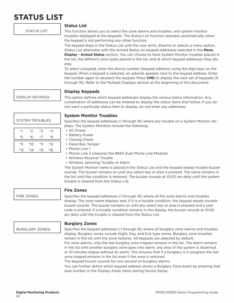
Digital Monitoring Products XR150/XR550 Series Programming Guide42
STATUS LISTStatus ListThis function allows you to select the zone alarms and troubles, and system monitor troubles displayed at the keypads. The Status List function operates automatically when the keypad is not performing any other function.The keypad stays in the Status List until the user arms, disarms or selects a menu option. Status List al ternates with the Armed Status on keypad addresses selected in the Menu Display - Armed Status section. You can choose to have Sys tem Monitor troubles placed in the list, the differ ent zone types placed in the list, and at which keypad addresses they dis-play. To select a keypad, enter the device number (keypad address) using the digit keys on the keypad. When a keypad is selected, an asterisk appears next to the keypad address. Enter the number again to deselect the keypad. Press CMD to display the next set of keypads (9 through 16). Refer to the Multiple Displays section at the beginning of this document.
Display KeypadsThis option defines which keypad ad dresses display the various status information. Any combination of addresses can be en tered to display the status items that follow. If you do not want a particular status item to dis play, do not enter any ad dresses.
System Monitor TroublesSpecifies the keypad addresses (1 through 16) where any trouble on a System Monitor dis-plays. The System Monitors include the following:• AC Power• Battery Power• Closing Check• Panel Box Tamper• Phone Line 1• Phone Line 2 (requires the 893A Dual Phone Line Module)• Wireless Receiver Trouble• Wireless Jamming Trouble or Alarm
The System Monitor name is placed in the Status List and the keypad steady trouble buzzer sounds. The buzzer remains on until any select key or area is pressed. The name remains in the list until the condition is re stored. The buzzer sounds at 10:00 am daily until the system trouble is cleared from the Status List.
Fire ZonesSpecifies the keypad addresses (1 through 16) where all fire zone alarms and troubles display. The zone name displays and, if it is a trouble condition, the keypad steady trouble buzzer sounds. The buzzer remains on until any select key or area is pressed and a user code is entered. If a trouble condition remains in the display, the buzzer sounds at 10:00 am daily until the trouble is cleared from the Status List.
burglary ZonesSpecifies the keypad addresses (1 through 16) where all burglary zone alarms and troubles display. Bur glary zones in clude Night, Day, and Exit type zones. Burglary zone troubles remain in the list until the zone restores. All keypads are selected by default.For zone alarms, only the last burglary zone tripped re mains in the list. The alarm remains in the list un til another burglary zone goes into alarm, any area of the system is dis armed, or 10 minutes elapse without an alarm. This ensures that if a bur glary is in progress the last zone tripped remains in the list even if the zone is restored.The keypad buzzer sounds for one second on bur glary alarms.You can further define which keypad address shows a Burglary Zone event by entering that area number in the Display Areas menu during Device Setup.
STATUS LIST
DISPLAY KEYPADS
SYSTEM TROUBLES
*1 *2 *3 *4
*5 *6 *7 *8
*9 *10 *11 *12
*13 *14 *15 *16
FIRE ZONES:
BURGLARY ZONES:

XR150/XR550 Series Programming Guide Digital Monitoring Products43
Supervisory ZonesSpecifies the keypad addresses (1 through 16) where all su pervisory zone alarms and troubles display. Supervisory zones are entered in the sta tus list and sound the keypad buzzer until a valid user code is entered at any keypad address. If a trouble condition remains in the display, the buzzer sounds at 10:00 am daily until the supervisory trouble is cleared from the Status List.
Panic ZonesSpecifies the keypad addresses (1 through 16) where all panic zone alarms and troubles display. The name of the zone remains in the list until a Sensor Reset is performed. The keypad will sound if the Bell Action is enabled in Bell Options.
Emergency ZonesSpecifies the keypad addresses (1 through 16) where all emer gency zone alarms and troubles display. The name of the zone remains in the list until the zone re stores. The keypad buzzer does not sound for emer gency alarms or troubles.
Auxiliary 1 ZonesSpecifies the keypad addresses (1 through 16) where all Aux iliary 1 zone alarms and troubles display. The name of the zone remains in the list until the zone restores. The keypad buzzer does not sound for Auxiliary 1 alarms or troubles. You can further define which keypad address shows an Auxiliary 1 Zone event by entering that area number in the Display Areas menu during Device Setup.
Auxiliary 2 ZonesSpecifies the keypad addresses (1 through 16) where all Aux iliary 2 zone alarms and troubles display. The name of the zone remains in the list until the zone restores. The keypad buzzer does not sound for Auxiliary 2 alarms or troubles.You can further define which keypad address shows an Auxiliary 2 Zone event by entering that area number in the Display Areas menu during Device Setup.
Carbon Monoxide ZonesSpecifies the keypad addresses (1 through 16) where all carbon monoxide zone alarms and troubles display. Carbon monoxide zones are entered in the sta tus list and sound the keypad buzzer until a valid user code is entered at any keypad address. If a trouble condition remains in the display, the buzzer sounds at 10:00 am daily until the carbon monoxide trouble is cleared from the Status List.
Communication TroubleSpecifies when communication troubles are displayed on keypads that are programmed to display System Monitor Troubles. Default is NO.Select YES to display communication trouble when any communication path fails.Select ALL to display communication trouble only when all paths have failed.
SPRVISORY ZONES:
PANIC ZONES:
EMERGENCY ZONES:
AUX 1 ZONES:
AUX 2 ZONES:
CO ZONES:
COMM PATH TRBL: NO YES ALL
PC LOG REPORTS
Digital Monitoring Products XR150/XR550 Series Programming Guide44
PC LOG REPORTSPC Log ReportsThis section allows you to program the types of PC Log Reports the panel sends through the ETHERNET Port directly on the panel. The reports include information such as the type of activity, time and date of the activity, and user name and number. These data reports can be accessed from a PC using the Advanced Reporting Module. See the XR150/XR550 Series Installation Guide (LT-1233) for detailed Ethernet setup information or the XR150/XR550 Users Guide (LT-1278) for more information.If there is trouble with the network connection, the panel continues to attempt to send the PC Log Reports until the connection is reestablished. The panel then sends the reports. A Network Trouble message is NOT sent if the connection is lost since this report tool is not designed to be monitored by a receiver. The PC Log Reports have the lowest priority of panel reports sent.The PC Log Address String entered CANNOT be the same as that entered in Communication. The PC Log Reports option should NOT replace the primary communication method or act as a backup communication method.
Net IP AddressThis option displays when the Communication Type for PC Log Reports is NET. Enter the IP address containing up to 16 characters. The Net IP Address must be unique and cannot be duplicated on the network. Enter all 12 digits and leave out the periods. The default is 0.0.0.0.
Net PortThis option displays when Communication Type for PC Log Reports is Net. Enter the Port number. Valid numbers are from 0 to 65535. Default is 2001.
Arm and Disarm ReportsSends arming, disarming and Late to Close events. Includes the area number, name and action, the user number and name, and the time and date.
Zone ReportsSends changes in the status of active zones. Includes the zone number, name, type, the action (alarm, trouble, bypass, etc.), user number (if applicable), and area name. For a Walk Test, zone verify and zone fail messages are sent for each zone.
User Command ReportsSends user code changes, schedule changes, and door access denied events.
Door Access ReportsSends door access activity: door number, user number and name, and time and date.
Supervisory ReportsSends system monitor reports, such as AC and battery, and system event reports. Supervisory Reports also sends the following reports:
• Abort• Exit Error• Ambush• System Recently Armed• Alarm Bell Silenced • Unauthorized Entry• Late to Close*
*Only sent as a Supervisory Report if Area Schedules is not enabled, Closing Check is enabled, and an opening/closing schedule has been programmed.
To send these reports to the PC Log, you must enable SUPV MSG.
PC LOG REPORTS
NET IP ADDRESS000.000.000.000
NET PORT 2001
ARM/DIS NO YES
ZONE NO YES
USR CMDS NO YES
DOOR ACS NO YES
SUPV MSG NO YES
XR150/XR550 Series Programming Guide Digital Monitoring Products45
PC Log Real-Time StatusSelect YES to send Real-Time Status reports for zones, doors, and outputs. The specific reports must also be selected by individual zone or output. The Real-Time Status messages are sent to a PC running a graphic display software. Default is NO.The messages that can be sent are:• Door Open with zone number• Door Closed with zone number• Door Open with door number• Door Closed with door number• Output On• Output Off• Output Pulse• Output Temporal
PC LOG REAL-TIMESTATUS NO YES
Digital Monitoring Products XR150/XR550 Series Programming Guide46
AREA INFORMATIONArea InformationAllows you to activate areas and assign functions to the different areas in the system. All non-24-hour zones must be assigned to an active area. See Zone Information.
You activate an area by assigning it a name.
Exit DelayEnter the exit delay time for all Exit type zones in this area. When the exit delay time starts, all activity on that zone and other non-24-hour zone types in the area is ig nored until the exit delay expires. The keypad displays the Exit Delay time countdown and annunciates the Exit Delay tone at 8 second intervals until the last 10 seconds when annunciation is at 3 second intervals.The exit de lay can be from 30 to 250 sec onds. Default is 60 seconds.During Exit Delay, if an exit zone trips, then restores, and trips again, the Exit Delay timer restarts. This restart can occur only once.
Exit Error Operation: At arming, when an entry/exit zone (EX) is faulted at the end of the exit delay then one of two sequences occur:
For Entry Delay 1 EX type zones:• The bell sounds for the length of time set in Bell Cutoff programming• The Entry Delay operation starts requiring code entry to disarm• If not disarmed, a zone alarm and an exit error are sent to the receiver
For Entry Delay 2-4 EX type zones:• The zone is force armed and a zone force arm message is sent to the receiver• An Exit Error is sent to the receiver• The bell sounds for the length of time set in Bell Cutoff programming
Closing CheckSelect YES to enable the panel to verify that all areas in the system are armed after permanent or extended sched ules ex pire. If the Clos ing Check finds any areas disarmed past the sched uled time, the keypads selected to display System Trouble Status displays CLOSING TIME! and emits a steady beep. When Area Schedules is set to YES in Area Information, the specific area and name display followed by — LATE.When Auto Arm is NO, if within ten minutes the system is not armed or if the schedule is not extended, a Late to Close report is sent to the SCS-1R Receiver. When Auto Arm is YES, the area arms. If the area becomes disarmed outside of any schedule, the Closing Check sequence occurs after the Late Arm Delay time. When Closing Check is NO and Auto Arm is YES, the system immediately arms when the schedule expires. No warning tone occurs.In addition, when Closing Check is NO, the option to extend a schedule does not display when the schedule expires.
Closing CodeWhen YES is selected, a code number is required for system arming. If NO is selected, a code number is not required for system arming.
Any bypassWhen YES is selected, zones can be bypassed without a code number during the arming sequence. A code number is always required to use the Bypass Zones option from the menu.
Area SchedulesSelect YES to allow each area to follow individual sets of area schedules programmed in the User Menu. Select NO for all areas to follow only one set of schedules in the User Menu. See the panel User Guide (LT-1278) to add schedules to the panel. Area Schedules are not designed to operate with All/Perimeter or Home/Sleep/Away systems.
AREA INFORMATION
EXIT DELAY: 60
CLS CHK NO YES
CLS CODE NO YES
ANY BYPS NO YES
AREA SCH NO YES
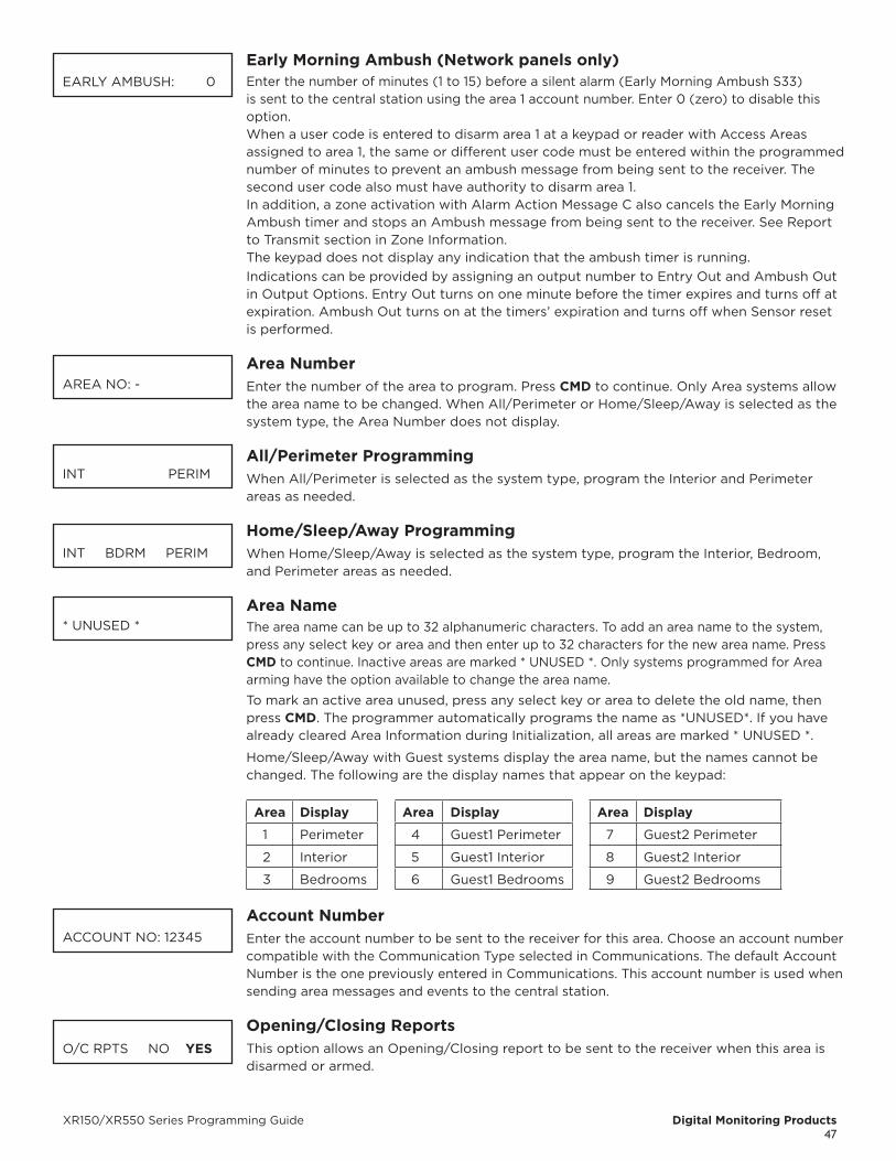
XR150/XR550 Series Programming Guide Digital Monitoring Products47
Early Morning Ambush (Network panels only)Enter the number of minutes (1 to 15) before a silent alarm (Early Morning Ambush S33) is sent to the central station using the area 1 account number. Enter 0 (zero) to disable this option.When a user code is entered to disarm area 1 at a keypad or reader with Access Areas assigned to area 1, the same or different user code must be entered within the programmed number of minutes to prevent an ambush message from being sent to the receiver. The second user code also must have authority to disarm area 1.In addition, a zone activation with Alarm Action Message C also cancels the Early Morning Ambush timer and stops an Ambush message from being sent to the receiver. See Report to Transmit section in Zone Information.The keypad does not display any indication that the ambush timer is running.Indications can be provided by assigning an output number to Entry Out and Ambush Out in Output Options. Entry Out turns on one minute before the timer expires and turns off at expiration. Ambush Out turns on at the timers’ expiration and turns off when Sensor reset is performed.
Area NumberEnter the number of the area to program. Press CMD to continue. Only Area systems allow the area name to be changed. When All/Perimeter or Home/Sleep/Away is selected as the system type, the Area Number does not display.
All/Perimeter ProgrammingWhen All/Perimeter is selected as the system type, program the Interior and Perimeter areas as needed.
Home/Sleep/Away ProgrammingWhen Home/Sleep/Away is selected as the system type, program the Interior, Bedroom, and Perimeter areas as needed.
Area NameThe area name can be up to 32 alphanumeric characters. To add an area name to the system, press any select key or area and then enter up to 32 characters for the new area name. Press CMD to continue. Inactive areas are marked * UNUSED *. Only systems programmed for Area arming have the option available to change the area name.
To mark an active area unused, press any select key or area to delete the old name, then press CMD. The programmer automatically programs the name as *UNUSED*. If you have already cleared Area Information during Initialization, all areas are marked * UNUSED *.
Home/Sleep/Away with Guest systems display the area name, but the names cannot be changed. The following are the display names that appear on the keypad:
Area Display Area Display Area Display
1 Perimeter 4 Guest1 Perimeter 7 Guest2 Perimeter
2 Interior 5 Guest1 Interior 8 Guest2 Interior
3 Bedrooms 6 Guest1 Bedrooms 9 Guest2 Bedrooms
Account NumberEnter the account number to be sent to the receiver for this area. Choose an account number compatible with the Communication Type selected in Communications. The default Account Number is the one previously entered in Communications. This account number is used when sending area messages and events to the central station.
Opening/Closing ReportsThis option allows an Opening/Closing report to be sent to the receiver when this area is disarmed or armed.
EARLY AMBUSH: 0
AREA NO: -
INT PERIM
INT BDRM PERIM
* UNUSED *
ACCOUNT NO: 12345
O/C RPTS NO YES
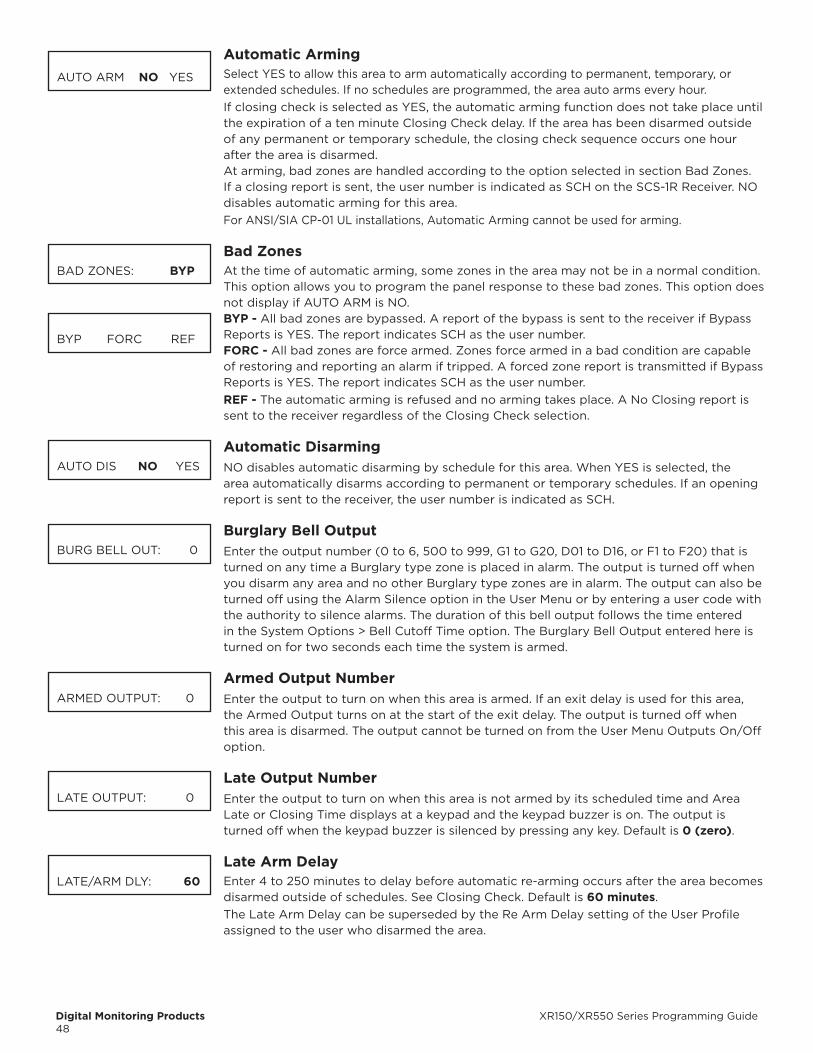
Digital Monitoring Products XR150/XR550 Series Programming Guide48
Automatic ArmingSelect YES to allow this area to arm automatically according to permanent, temporary, or extended schedules. If no schedules are programmed, the area auto arms every hour.If closing check is selected as YES, the automatic arming function does not take place until the expiration of a ten minute Closing Check delay. If the area has been disarmed outside of any permanent or temporary schedule, the closing check sequence occurs one hour after the area is disarmed.At arming, bad zones are handled according to the option selected in section Bad Zones. If a closing report is sent, the user number is indicated as SCH on the SCS-1R Receiver. NO disables automatic arming for this area.For ANSI/SIA CP-01 UL installations, Automatic Arming cannot be used for arming.
bad ZonesAt the time of automatic arming, some zones in the area may not be in a normal condition. This option allows you to program the panel response to these bad zones. This option does not display if AUTO ARM is NO.
bYP - All bad zones are bypassed. A report of the bypass is sent to the receiver if Bypass Reports is YES. The report indicates SCH as the user number.FORC - All bad zones are force armed. Zones force armed in a bad condition are capable of restoring and reporting an alarm if tripped. A forced zone report is transmitted if Bypass Reports is YES. The report indicates SCH as the user number.REF - The automatic arming is refused and no arming takes place. A No Closing report is sent to the receiver regardless of the Closing Check selection.
Automatic DisarmingNO disables automatic disarming by schedule for this area. When YES is selected, the area automatically disarms according to permanent or temporary schedules. If an opening report is sent to the receiver, the user number is indicated as SCH.
burglary bell OutputEnter the output number (0 to 6, 500 to 999, G1 to G20, D01 to D16, or F1 to F20) that is turned on any time a Burglary type zone is placed in alarm. The output is turned off when you disarm any area and no other Burglary type zones are in alarm. The output can also be turned off using the Alarm Silence option in the User Menu or by entering a user code with the authority to silence alarms. The duration of this bell output follows the time entered in the System Options > Bell Cutoff Time option. The Burglary Bell Output entered here is turned on for two seconds each time the system is armed.
Armed Output NumberEnter the output to turn on when this area is armed. If an exit delay is used for this area, the Armed Output turns on at the start of the exit delay. The output is turned off when this area is disarmed. The output cannot be turned on from the User Menu Outputs On/Off option.
Late Output NumberEnter the output to turn on when this area is not armed by its scheduled time and Area Late or Closing Time displays at a keypad and the keypad buzzer is on. The output is turned off when the keypad buzzer is silenced by pressing any key. Default is 0 (zero).
Late Arm DelayEnter 4 to 250 minutes to delay before automatic re-arming occurs after the area becomes disarmed outside of schedules. See Closing Check. Default is 60 minutes.The Late Arm Delay can be superseded by the Re Arm Delay setting of the User Profile assigned to the user who disarmed the area.
AUTO ARM NO YES
BAD ZONES: bYP
BYP FORC REF
AUTO DIS NO YES
BURG BELL OUT: 0
ARMED OUTPUT: 0
LATE OUTPUT: 0
LATE/ARM DLY: 60
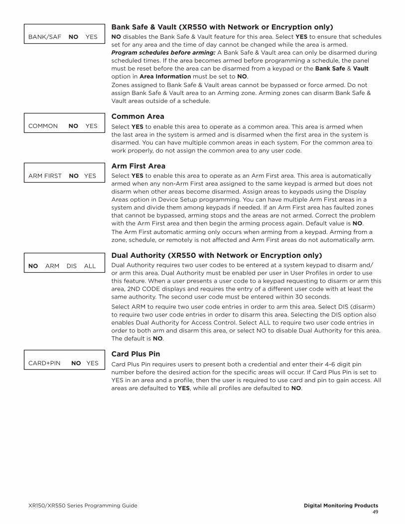
XR150/XR550 Series Programming Guide Digital Monitoring Products49
bank Safe & Vault (XR550 with Network or Encryption only)NO disables the Bank Safe & Vault feature for this area. Select YES to ensure that schedules set for any area and the time of day cannot be changed while the area is armed.Program schedules before arming: A Bank Safe & Vault area can only be disarmed during scheduled times. If the area becomes armed before programming a schedule, the panel must be reset before the area can be disarmed from a keypad or the bank Safe & Vault option in Area Information must be set to NO.Zones assigned to Bank Safe & Vault areas cannot be bypassed or force armed. Do not assign Bank Safe & Vault area to an Arming zone. Arming zones can disarm Bank Safe & Vault areas outside of a schedule.
Common AreaSelect YES to enable this area to operate as a common area. This area is armed when the last area in the system is armed and is disarmed when the first area in the system is disarmed. You can have multiple common areas in each system. For the common area to work properly, do not assign the common area to any user code.
Arm First AreaSelect YES to enable this area to operate as an Arm First area. This area is automatically armed when any non-Arm First area assigned to the same keypad is armed but does not disarm when other areas become disarmed. Assign areas to keypads using the Display Areas option in Device Setup programming. You can have multiple Arm First areas in a system and divide them among keypads if needed. If an Arm First area has faulted zones that cannot be bypassed, arming stops and the areas are not armed. Correct the problem with the Arm First area and then begin the arming process again. Default value is NO.The Arm First automatic arming only occurs when arming from a keypad. Arming from a zone, schedule, or remotely is not affected and Arm First areas do not automatically arm.
Dual Authority (XR550 with Network or Encryption only)Dual Authority requires two user codes to be entered at a system keypad to disarm and/or arm this area. Dual Authority must be enabled per user in User Profiles in order to use this feature. When a user presents a user code to a keypad requesting to disarm or arm this area, 2ND CODE displays and requires the entry of a different user code with at least the same authority. The second user code must be entered within 30 seconds.
Select ARM to require two user code entries in order to arm this area. Select DIS (disarm) to require two user code entries in order to disarm this area. Selecting the DIS option also enables Dual Authority for Access Control. Select ALL to require two user code entries in order to both arm and disarm this area, or select NO to disable Dual Authority for this area. The default is NO.
Card Plus PinCard Plus Pin requires users to present both a credential and enter their 4-6 digit pin number before the desired action for the specific areas will occur. If Card Plus Pin is set to YES in an area and a profile, then the user is required to use card and pin to gain access. All areas are defaulted to YES, while all profiles are defaulted to NO.
BANK/SAF NO YES
COMMON NO YES
ARM FIRST NO YES
NO ARM DIS ALL
CARD+PIN NO YES

Digital Monitoring Products XR150/XR550 Series Programming Guide50
ZONE INFORMATIONZone InformationZone Information allows you to define the operation of each protection zone used in the system. All protection zones are programmed the same way.
Zone NumberEnter the number of the zone you intend to program. Available zone numbers are shown in the table below.
Panel Programming Zone NumberOnboard 1-10
Keypad bus Programming Zone Number1 11-14
2 21-24
3 31-34
4 41-44
5 51-54
6 61-64
7 71-74
8 81-84
9 91-94
10 101-104
11 111-114
12 121-124
13 131-134
14 141-144
15 151-154
16 161-164
1100 Series Wireless Programming Zone Number1144 Series Key Fob 400-449
LX-bus Programming Zone NumberLX-Bus 500 500-599
LX-Bus 600 600-699
LX-Bus 700 700-799
LX-Bus 800 800-899
LX-Bus 900 900-999
Press CMD to enter a zone name.
Zone NameZone names can have up to 32 alphanumeric characters. A name must be given to each zone in the system. The name can display at the keypads during arming and disarming so the user does not have to memorize zone numbers. A zone that is not part of the system must be marked unused.To add a zone name to the system, press any select key or area and then enter up to 32 characters for the new zone name. Press CMD to continue.To mark a zone unused, de lete the old name by pressing any select key or area, then press CMD. The pro grammer auto matically pro grams the name as * UNUSED *. If you have already cleared Zone Information during Initialization, the zones is marked * UNUSED *.
ZONE INFORMATION
ZONE NO: -
* UNUSED *
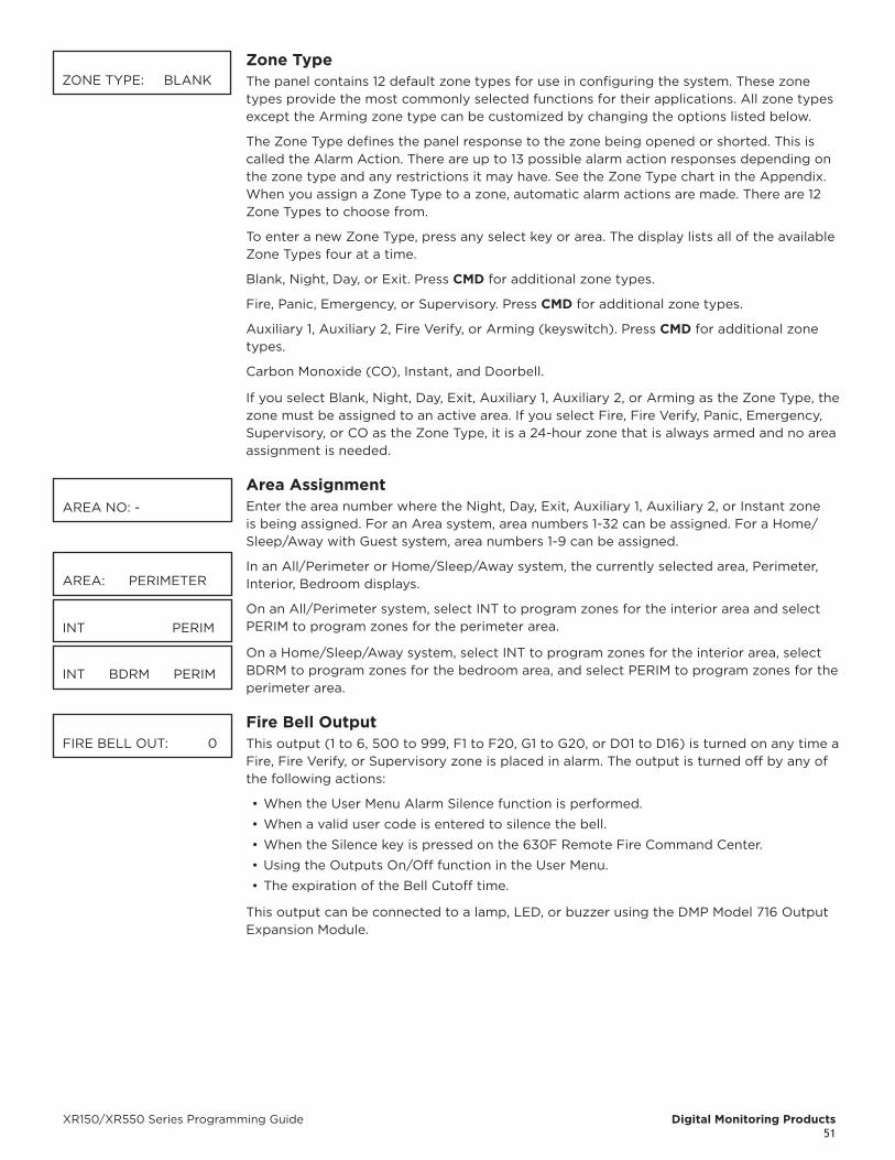
XR150/XR550 Series Programming Guide Digital Monitoring Products51
Zone TypeThe panel contains 12 default zone types for use in configuring the system. These zone types provide the most commonly selected functions for their applications. All zone types except the Arming zone type can be customized by changing the options listed below.
The Zone Type defines the panel response to the zone being opened or shorted. This is called the Alarm Action. There are up to 13 possible alarm action responses depending on the zone type and any restrictions it may have. See the Zone Type chart in the Appendix.When you assign a Zone Type to a zone, automatic alarm actions are made. There are 12 Zone Types to choose from.
To enter a new Zone Type, press any select key or area. The display lists all of the available Zone Types four at a time.
Blank, Night, Day, or Exit. Press CMD for additional zone types.
Fire, Panic, Emergency, or Supervisory. Press CMD for additional zone types.
Auxiliary 1, Auxiliary 2, Fire Verify, or Arming (keyswitch). Press CMD for additional zone types.
Carbon Monoxide (CO), Instant, and Doorbell.
If you select Blank, Night, Day, Exit, Auxiliary 1, Auxiliary 2, or Arming as the Zone Type, the zone must be assigned to an active area. If you select Fire, Fire Verify, Panic, Emergency, Supervisory, or CO as the Zone Type, it is a 24-hour zone that is always armed and no area assignment is needed.
Area AssignmentEnter the area number where the Night, Day, Exit, Auxiliary 1, Auxiliary 2, or Instant zone is being assigned. For an Area system, area numbers 1-32 can be assigned. For a Home/Sleep/Away with Guest system, area numbers 1-9 can be assigned.
In an All/Perimeter or Home/Sleep/Away system, the currently selected area, Perimeter, Interior, Bedroom displays.
On an All/Perimeter system, select INT to program zones for the interior area and select PERIM to program zones for the perimeter area.
On a Home/Sleep/Away system, select INT to program zones for the interior area, select BDRM to program zones for the bedroom area, and select PERIM to program zones for the perimeter area.
Fire bell OutputThis output (1 to 6, 500 to 999, F1 to F20, G1 to G20, or D01 to D16) is turned on any time a Fire, Fire Verify, or Supervisory zone is placed in alarm. The output is turned off by any of the following actions:
• When the User Menu Alarm Silence function is performed.
• When a valid user code is entered to silence the bell.
• When the Silence key is pressed on the 630F Remote Fire Command Center.
• Using the Outputs On/Off function in the User Menu.
• The expiration of the Bell Cutoff time.
This output can be connected to a lamp, LED, or buzzer using the DMP Model 716 Output Expansion Module.
ZONE TYPE: BLANK
AREA NO: -
AREA: PERIMETER
INT PERIM
INT BDRM PERIM
FIRE BELL OUT: 0
Digital Monitoring Products XR150/XR550 Series Programming Guide52
Arming Zone Area AssignmentIn an Area or Home/Sleep/Away with Guest system, if the zone has been programmed as an Arming Type (AR), enter the areas that the zone controls.
When the zone changes from normal to shorted, the programmed areas toggle between the armed or disarmed condition using the Style programming below. When restored to normal, no action occurs. When the zone is opened from a normal (disarmed) state, a trouble is reported. When opened from a shorted (armed) state, an alarm is reported and the zone is disabled until you disarm the area(s) from either a keypad, Virtual Keypad, or Remote Link™ computer.
To visually indicate the armed state of the area(s), you can assign an Armed Output to individual areas and use remote LEDs at the keyswitch. The LED turns on or off to indicate to the user the armed state of the area(s).
Perimeter/All - Specify whether the arming zone arms just the Perimeter (PERIM) or the Perimeter and Interior areas (ALL) for All/Perimeter systems. When disarming, all areas are disarmed.
Home/Sleep/Away - Specify whether the arming zone arms the Perimeter (HOME), the Perimeter and Interior (SLEEP), or all three areas (AWAY). When disarming, all areas are disarmed.
Arming Zone OperationIf any bad zones are present when the Arming zone is shorted, the LED delays lighting for 5 seconds. If during the 5-second delay the Arming zone is shorted again no arming takes place. If 5 seconds expire without the zone shorting again or restoring to normal, the areas arm and bad zones are force armed. To allow bad zones to be force armed, the Any Bypass option must be set to YES. If Any Bypass option is set to NO, arming does not occur. See the Area Information - Any Bypass section. A priority zone cannot be force armed.
StyleThis option specifies the style for the arming/disarming operation. The default style is TGL (toggle). Press any select key or area to display the STYLE options. To view more style options press CMD.
TGL (Toggle) - When the zone changes from disarmed to armed, the programmed areas toggle between the armed or disarmed condition. When restored to disarmed, no action occurs. When the zone is opened from a disarmed state, a trouble is reported. When opened from a armed state, an alarm is reported and the zone is disabled until you disarm the area(s) from either a keypad, Remote Link™, or Virtual Keypad.
ARM - When the zone is armed, the programmed areas are armed. When restored to disarmed, no action occurs. When the zone is opened from a disarmed state, a trouble is reported. When opened from a armed state, an alarm is reported.
DIS (Disarm) - When programmed as an Area system, a short will disarm the programmed areas. When programmed as a ALL/PERIM or HOME/AWAY system, a short will disarm ALL areas. When restored to normal, no action occurs. When the zone is opened from a normal (disarmed) state, a trouble is reported.
STEP - When programmed as an AREA system, the Arming Type areas will arm and beep the keypads once. When programmed as ALL/PERIM or HOME/AWAY, on the first short HOME will arm and beep the keypad once. On the second short, SLEEP will arm and beep the keypads twice. On the third short, AWAY will arm and beep the keypad three times. A normal condition will cause no action. An open condition will disarm the programmed areas and beep the keypads for one second.
MNT (Maintain) - When the zone is shorted, the programmed areas are armed. When restored to normal, the programmed areas are disarmed and any alarm bells are silenced. When the zone is opened from a normal (disarmed) state, a trouble is reported. If opened from a shorted (armed) state, an alarm is reported and the zone is disabled until you disarm the area(s) from either a keypad, Virtual keypad, or Remote Link™ computer.
ARM/DIS AREAS
ARM AREAS: PERIM
PERIM ALL
HOME SLEEP AWAY
STYLE:
TGL ARM DIS STEP
MNT
XR150/XR550 Series Programming Guide Digital Monitoring Products53
Expander Serial NumberIf using a zone expansion module, enter the 10 character serial number found on the module. Press CMD to move to the next prompt.
Already In Use displays when the serial number is already programmed for another zone. The programmed zone number displays.
Next ZoneSelect YES to terminate zone programming. The display returns to Zone Number, allowing you to enter a new zone number. Select NO to make alter ations to the Alarm Action for a zone.
To program zones for wireless operation, select NO at the NEXT ZONE - NO YES option. The WIRELESS NO YES option displays. If the zone you are programming is intended for wireless devices, select YES. Select NO to continue programming non-wireless zones in the 500 to 999 range.
• Zones 400 to 449 can be programmed for 1144 Series Key Fobs
• Zones 500 through 599 can be programmed for DMP 1100 Series Wireless on an XR150 Series panel
• Zones 500 through 999 can be programmed for DMP 1100 Series Wireless on an XR550 Series panel
WirelessSelect YES to program this zone as a DMP wireless zone. You must program the wireless House Code prior to adding DMP wireless zones to the system. See House Code programming in System Options. Default is NO.
Competitor WirelessSelect YES to program this zone as a wireless zone if using the 1100T Wireless Translator. You must program the wireless House Code prior to adding wireless zones to the system. See House code programming in System Options. Default is NO.
Competitor Wireless Serial NumberIf using an 1100T Wireless Translator, you can press the first top row select key and manually enter the eight character serial number found on the wireless device. Once the signal is detected and read, the device serial number will display on the keypad screen. To transmit the serial number to the panel automatically, select the LRN option. When TRANSMIT NOW appears on the keypad, tamper the transmitter that is being paired. Once the panel has received the tamper signal, the serial number will display on the keypad.
Serial Number EntryEnter the eight-digit serial number found on the DMP wireless device.Already In Use displays when the serial number is already programmed for another zone. The programmed zone number displays.
ContactTransmitter Contact displays if the serial number entered is for an 1101, 1103, or 1106 Universal Transmitter or 1114 Wireless Four-Zone Expander. Press any select key or area to select the contact.Select INT to use the internal reed switch contacts. Select EXT to connect an external device to the 1101, 1103, or 1106 terminal block. Default is INTERNAL.
By allowing both of the transmitter contacts (INT and EXT) to be used at the same time, two zones may be programmed from one transmitter. When using both contacts, you must use consecutive zone numbers. The same serial number is used for both zones.Contact Selection option displays when programming the 1114 Wireless Four-Zone Expander with four input contacts. The same serial number is used for all four contacts. Select the contact number to program. When using the contacts, you must use consecutive zone numbers. Default is Contact 1.A tamper on the 1114 is transmitted as the zone number assigned to Contact 1.
EXP SN:
NEXT ZN? NO YES
ZONE INFORMATIONWIRELESS? NO YES
COMP WLS? NO YES
COMP WLS SRL #: -
TRANSMITTERSERIAL#: XXXXXXXX
TRANSMITTER CONTACT: XXXXXXXX
TRANSMTR CONTACTINT EXT
TRANSMTR CONTACT 1 2 3 4

Digital Monitoring Products XR150/XR550 Series Programming Guide54
Already In Use message displays when the Contact is already programmed for another zone. The programmed zone number displays.
When EXT is selected as the Contact type, external devices connected to the 1101, 1103 or 1106 terminal block, select NO to use normally closed (N/C) contacts. Select YES to use normally open (N/O) contacts. Default is NO.
Supervision TimePress any select key or area to select the supervision time required for the wireless zone. Press CMD to accept the default time. Default is 240 minutes.
Refer to the Wireless Check-in and Supervision Time Definitions section of the Appendix for supervision information.
Press the select key or area under the required number of minutes. The transmitter must check in at least once during this time or a missing condition is indicated for that zone. 1100 Series transmitters automatically checkin based on the supervision time selected for the wireless zone, no additional programming is needed. If two zones share the same transmitter, the last programmed supervision time is stored as the supervision time for both zones. Zero (0) indicates an unsupervised transmitter.
The 3 minute supervision time is only available for zone types of Fire (FI), Fire Verify (FV), Supervisory (SV), and Carbon Monoxide (CO).
When the panel is reset or a receiver is installed or powered down and powered up, the supervision timer restarts for all wireless zones.
LED OperationSelect YES to turn on an 1142 Hold-up transmitter LED during Panic or Emergency operation. Select NO to turn the LED off during Panic or Emergency operation. The LED always operates when the transmitter case is open and the tamper is faulted. Default is YES.
Disarm/DisableSelect YES to disable the Zone Tripped message from 1101/1102/1106 Universal Transmitters (Version 108 of higher software), 1103 Universal Transmitters (Version 107 or higher software) or 1122/1126/1127 PIRs during the disarmed period. When disarmed, the transmitter or PIR only sends Supervision, Tamper, and Low Battery messages to extend transmitter battery life. For transmitters, a Zone Tripped message is sent if the zone remains tripped for 20 seconds. Select NO to always send Zone Tripped messages in addition to Supervision, Tamper, and Low Battery. Default is YES.
PIR Pulse CountSelect the number of infrared pulses (2 or 4) the 1122, 1126, or 1127 PIR should sense before sending a short message to the 1100X Series Receiver. Default is 4.
PIR SensitivitySelect the sensitivity setting for an 1122, 1126, or 1127 PIR. Selecting LOW sets the PIR to operate at 75% sensitivity for installations in harsh environments. Selecting HIGH sets the PIR to maximum sensitivity. Default is LOW.
Pet ImmunityThis option displays for the 1122 Wireless PIR Motion Detector. Select whether or not to enable pet immunity. Selecting YES allows pet immunity for animals up to 55 pounds. Default is NO.
Next ZoneSelect YES to return to the ZONE NO: - option to program a new zone. Select NO to display the Alarm Action option. Press CMD to continue.
ALREADY IN USEZONE NUMBER: XXX
ZONE INFORMATIONNORM OPN NO YES
TRANSMITTERSUPRVSN TIME: 240
SELECT MINUTES: 0 3 60 240
LED OPERATION NO YES
DISARM DISABLE NO YES
WIRELESS PIRPULSE COUNT: 4
WIRELESS PIR SENSITIVITY: LOW
WIRELESS PIR PETIMMUNITY: NO YES
NEXT ZONE NO YES
XR150/XR550 Series Programming Guide Digital Monitoring Products55
V-Plex Serial Number EntryIf installing a 736V V-Plex module, enter the eight-digit serial number found on the V-Plex device. The serial number will start with the letter A, followed by a 7-digit serial number. In the address, A indicates that the device is a Honeywell product.
Alarm ActionThis option allows you to change any Zone Type standard definitions. When the Zone Type is specified, the Alarm Action for that zone is stored in memory.
Disarmed OpenDefines the action taken by the panel when the zone is opened while the area is disarmed. There are three actions to define: Report to transmit, Relay Output to activate, and Relay Output action.
You must also make these selections for the Disarmed Short, Armed Open, and Armed Short zone conditions. Press CMD to continue.
Report to TransmitPress any select key or area to display the following report options: A, T, L, S, C, and - (dash).
ALARM - Select Alarm (A) to send an alarm report to the receiver and activate the bell output according to zone type. The zone name appears in the panel alarmed zones and status lists.
TROUBLE - Select Trouble (T) to send a trouble report to the receiver. The zone name appears in the panel alarmed zones and status lists.
UL requirements prevent the Alarm (A) and Trouble (T) action for Fire (FI), and Fire Verify (FV) zone types from being changed.
LOCAL - When you select Local (L), an alarm report is NOT sent to the receiver. The bell output activates and the zone name appears in the panel alarmed zones and status lists.
- (Dash) - When you select a – (dash), reports are NOT sent to the receiver. The bell output does not activate and there is no display in the panel alarmed zones or status list. Only the relay output selected in the next section operates.
DOOR PROPPED - Selecting D allows the ENTRY DLY 4 in the System Option section to begin to count without displaying on keypad. If the time expires and the zone has not returned to normal, the keypad trouble buzzer starts and CLOSE THE DOOR appears on the keypads programmed into the PREWARN ADDRESS section. The time programmed into ENTRY DLY 4 begins to count down again internally. If the time expires a second time, and the zone has not returned to normal, the output (if programmed in zone information) triggers and a fault report is sent to the receiver and the zone name - OPEN message displays on the keypads until a code is entered.
SENSOR RESET - When the zone state changes, the bell is silenced, a Sensor Reset is performed and a Alarm Bell Silenced Message (S34) is sent.
CANCEL AMBUSH - Select C for the zone to cancel the Early Morning Ambush timer and stop an Ambush message from being sent to the receiver. Faulting the zone takes the place of a second user code being entered at the keypad and is only available for non-fire type zones. Area assignment for the zone does not affect this option. See Early Morning Ambush in Area Information programming .
Output NumberYou can specify any of the Relay Outputs on the panel to be activated by a zone condition (1 to 6, 500 to 999 if Model 716 used, D01 to D16, G1 to G20). The output can be activated regardless of the report to transmit or whether or not the zone is programmed as local. An output activated by an armed zone is turned off when the zone area is disarmed by a user.
To enter an output number, press any select key or area followed by the output number. Press CMD.
VPLEX DEVICESERIAL #: XXXXXXXX
ALARM ACTION . . . .
DISARMED OPEN
MSG: TROUBLE
A T L -
D S C
OUTPUT NO: 0
Digital Monitoring Products XR150/XR550 Series Programming Guide56
Output ActionOutput Action allows you to assign an output action to the relay: Steady, Pulse, Momentary, or Follow.
STEADY - The output is turned on and remains on until the area is disarmed, an output cutoff time expires, or the output is reset from the keypad menu.
PULSE - The output alternates one second on and one second off.
MOMENTARY - The output is turned on only once for one second.
FOLLOW - The output is turned on and remains on while the zone is in an off normal, or bad condition. When the zone restores, the output is turned off.
For Day Zone types, when an output is turned on, a user code with silence authority can turn the output off.
Disarmed Short, Armed Open, and Armed ShortAfter you make the three selections in the sections above, the display prompts for the same three selections for Disarmed Short, Armed Open, and Armed Short conditions. If the zone is a 24-hour type, only the Armed Open and Armed Short conditions display. When you have programmed all of the zone conditions, the Swinger Bypass selection then displays.
Swinger bypassSelecting YES allows the zone to be swinger bypassed by the panel according to the specifications pro grammed in Swinger Bypass Trips and Reset Swinger Bypass. The Bypass condition displays in the keypad Status List. Selecting NO disables swinger bypassing for this zone.
If within one hour, a zone trips the total number of times as specified in Swinger Bypass Trips, the panel bypasses it until the following conditions occur;
• The area in which the zone is assigned is disarmed
• The zone is manually reset through the Bypass Zones? keypad User Menu function
• The zone remains normal for one hour and the Reset Swinger Bypass is YES.
If the zone trips fewer than the specified times within one hour, the bypass trip counter returns to 0 (zero) and the process must be repeated.
A report of the swinger bypass is sent to the receiver if Bypass Reports is YES.
Prewarn Keypad AddressesAt the entry delay start, all keypad addresses selected here dis play ENTER CODE:-. If you want the prewarn to sound at all 16 addresses, leave the default setting.
To delete an address, press the matching number on the keypad. To disable prewarning at all keypads, press any select key or area to clear the addresses shown. Press CMD when the address selection is com plete.
The prewarn tone stops at the keypad where the first user code digit is entered. If no keys are pressed for five seconds or an invalid user code is entered, the prewarn tone resumes at that keypad.
ChimeOption is only shown for Night, Exit, and Instant zones. Select either NONE, DB (doorbell), ASC (ascend), or DSC (descend) to assign that tone to a zone. Default is DOORbELL for Exit zones and NONE for Night zones.
Entry DelaySelect the entry timer for this zone. Entry timers 1 to 4 are programmed in System Options.
Zone Retard DelayWhen you select YES, the zone operates with the zone retard delay. The retard func tions only in zone short condi tions. The zone must re main shorted for the full length of the retard de lay before the panel recognizes its condition. If you select NO, the zone operates without a retard delay.
OUTPUT: NONE
STD PLS MOM FOLW
SWGR BYP NO YES
PREWARN KEYPADS:
CHIME: DOORBELL
ENTRY DELAY: 1
RETARD NO YES
XR150/XR550 Series Programming Guide Digital Monitoring Products57
The zone must re main shorted for the full length of the re tard de lay before the panel recognizes its condition. If you select NO, the zone operates without a retard delay.
Presignal Keypad AddressesYou can enable any combina tion of keypad addresses to sound a presignal tone during the time a zone is in retard delay. The presignal tone si lences when the zone restores or the re tard delay expires. To en able a presignal ad dress, press any select key or area followed by the number of the keypad address. You can enable the presignal for all 16 keypad addresses. To disable a presignal address press the matching number digit again. Press CMD when the address selection is complete. The Presignal option is only displayed when Retard is selected as YES.
Fast ResponseSelect YES to provide a zone response time of 167ms. Select NO to provide a normal zone response time of 500ms. Zones 500 to 999 have a fixed response time and do not display this option.
Cross ZoneSelect YES to enable cross zoning for this zone. Cross zoning requires one or more armed zones to fault within a programmed time before an alarm report is sent to the receiver.
When the first cross zoned zone trips, the cross zone time specified in System Options begins to count down. When a second cross zoned zone trips or the first zone trips a second time before the end of the count down, the bell action assigned to the zone activates and the panel sends an alarm report for both zones.
If no other cross zoned zone trips before the cross zone time expires, the panel sends only a zone fault report to the receiver.
Cross zoning is not compatible with all zone types: You can not enable cross zoning for Fire verify zones or for any Fire zones that have Retard Delay enabled.
PrioritySelect YES to provide additional protection for the premises by requiring this zone to be in a normal condition before its assigned area can be armed.
Fire Panel Slave InputThis option is available on Fire Zones (FI) only and allows a fire zone the ability to provide slave communication operation for a separate fire alarm control panel. If YES, this zone will transmit a restoral immediately when restored by the fire panel being monitored. A sensor reset is not required to generate the restoral message.If NO, this zone will operate as a standard fire type zone and a sensor reset is required before the zone will return to normal. Default is NO.
Area FollowerAllows Night, Day, Aux 1, or Aux 2 burglary zones to be delayed by following any exit or entry delay that is currently running in the area that is specified. Default is 0.
Zone Real-Time StatusSelecting YES allows Real-Time Status reports, such as Door Open or Closed with zone number, to be sent using PC Log reporting. Selecting NO disables Real-Time Status for this zone. Default is NO.
Traffic CountTraffic Count is only displayed for NT, EX, and IN type zones. Select YES to provide reporting to the receiver of the number of zone trips while in a disarmed state. The number of trips will be included with the area closing message and reported to the central station automation system. Traffic Count data for the 10 lowest numbered zones with Traffic Count set to YES is also sent to the Virtual Keypad TM App if enabled at dealer.securecomwireless.com. Default is NO.
PRESGNL KEYPADS:
FAST RSP NO YES
CRS ZONE NO YES
PRIORITY NO YES
FIRE PANEL SLAVE INPUT: NO YES
FOLLOW AREA: 0
ZONE REAL TIME STATUS NO YES
TRAFFIC COUNT NO YES
Digital Monitoring Products XR150/XR550 Series Programming Guide58
Zone Audit DaysEnter the number of days (0 to 365) allowed to elapse without the zone being tripped before a fault message is sent. The message is sent to the receiver(s) programmed to receive Supervisory/Trouble Reports at 10:00 am following the expiration of the timer. Each time the zone is tripped, the Zone Audit Days timer restarts and begins to countdown the number of days programmed. After the countdown expires, a fault message is sent and the Zone Audit Days timer restarts and begins to countdown the number of days programmed. Available for all zone types except fire and fire verify. Enter 0 (zero) to disable this function. Default is 0 (zero).
Report with Account Number for AreaThis option is only available for 24-hour zone types (Fire, Fire Verify, Panic, Emergency, or Supervisory).Enter the area number (1-32) to assign as a 24-hour zone type. This option sends the account number of the programmed area with messages. If the entered area number does not exist or is not valid, the account number programmed in the Communication section is sent. Select 0 (zero) to have the report sent with the account number programmed in Communication. Default is 0.
LockdownThis option is available when programming a Panic type zone. Selecting YES triggers a lockdown when a panic zone is tripped. Default is NO.
1144 SERIES KEY FObSFor an 1144 Series Key Fob set the House Code from 1 to 50. See House Code programming in System Options. Only zones 400 to 449 can be programmed as 1144 Series Key Fob zones. Refer to the 1100 Series Key Fob Programming Sheet (LT-0706) supplied with the 1100X Series Wireless Receiver and the 1144 Series Key Fob Install Guide (LT-1449) as needed.
To operate arming and disarming properly, the Key Fob should be assigned to a User Number with appropriate area assignments, however, the User Number does not have to exist at the time the Key Fob is programmed. The Key Fob User Number can be added later by the User.
The following programming continues from the Zone Number section when zone 400-449 is selected.
Key Fob User NumberEnter the User Number (1-9999) used to identify the key fob user and their arming and disarming authority. Default is blank.
User Not in Use displays when the User Number entered does not exist in User Code programming. The key fob can be added, but the user must eventually be added to cause the key fob to operate.
Key Fob Serial NumberEnter the eight-digit serial number found on the wireless device.
Key Fob Supervision TimePress any select key or area to select the supervision time required for the key fob zone. Press CMD to accept the default time. Default is 0 for key fobs.
Press the select key or area under the required number of minutes. The key fob must check in at least once during this time or a missing condition is indicated for that zone. 1144 Series key fobs automatically checkin based on the supervision time selected for the wireless zone, no additional programming is needed. Zero (0) indicates an unsupervised transmitter.
When the panel is reset or a receiver is installed or powered down and powered up, the supervision timer restarts for all wireless zones.
ZONE AUDIT DAYS:
REPORT WITH ACCTNO. FOR AREA: 0
LOCKDOWN:NO YES
KEY FOB USERNUMBER: XXXX
USER XXXX NOT IN USE
TRANSMITTER SERIAL#: XXXXXXXX
TRANSMITTERSUPRVSN TIME: 0
SELECT MINUTES: 0 60 240
XR150/XR550 Series Programming Guide Digital Monitoring Products59
Number of Key Fob buttonsEnter the number of buttons (1, 2, or 4) on the key fob being programmed.
If the key fob is a one-button model, programming continues at the Button Action section. Default button assignment for one-button key fobs is a Panic Alarm (PN) with no output assigned.
Key Fob button Selection (Four buttons)If the key fob being programmed is a four-button model, press the select key or area under the key fob button to program. The following list identifies the default button assignments:
TOP Arming with no areas assigned
BTM Disarming with no areas assigned
LFT Panic Alarm (PN) with no output assigned
RGT Arming with Area 1 assigned
Key Fob button Selection (Two buttons)If the key fob being programmed is a two-button model, press the select key or area under the key fob button to program. The following list identifies the default button assignments:
TOP Arming with no areas assigned
BTM Disarming with no areas assigned
button ActionSpecify the Button Action for an individual key fob button. The default action for the button selected is displayed. Press any select key or area to display the Button Action options. To view more options press CMD. yyy = the name of the button being programmed (TOP, BTM, LFT, RGT).
ARM (Arm) - Arms selected areas and force arms bad zones.DIS (Disarm) - Disarms selected areas.TGL (Toggle Arm) - Toggles arm/disarm for selected areas and force arms bad zones when arming.STA (Status) - Causes the key fob LED to indicate the arm/disarm status of the system.PN (Panic) - Triggers a Panic zone type alarm with no restoral.PN2 (Panic 2) - Triggers a Panic zone type alarm with no restoral when pressed simultaneously with any other Panic 2 button. No action occurs when pressed alone.EM (Emerg) - Triggers an Emergency zone type alarm with no restoral.EM2 (Emerg 2) - Triggers an Emergency zone type alarm with no restoral when pressed simultaneously with any other Emergency 2 button. No action occurs when pressed alone.OUT (Output) - Causes an output to turn on steady, pulse, momentary, toggle, or off.RST (Sensor Reset) - Causes the panel to perform a standard Sensor Reset.UN (Unused) - The button is not used and performs no action.
button Press TimeButton Press Time specifies the amount of time (SHORT or LONG) the user must press the button before the key fob sends a message to the wireless receiver. The default press time displays. Press any select key or area to set the Button Press Time for Arm, Disarm, Toggle, Status, Output, and Sensor Reset.
SHORT - Press the button for one-half (1/2) second to send the message to the wireless receiver.LONG - Press the button for two (2) seconds to send the message to the wireless receiver.
Arm/Disarm Area SelectionIn an Area system or Home/Sleep/Away with Guest system, this specifies the areas to be armed/disarmed by the Key Fob button being programmed. To select an area between 1 and 32, enter the area number using the keypad digit keys. Default is no areas enabled.
In order to arm or disarm selected areas, the Profile assigned to the User Number needs to have the same area numbers selected. Any area may be selected at Arm/Disarm Areas but only matching area numbers are armed or disarmed when the specific button is pressed.
NO. OF KEY FOBBUTTONS: X
BUTTON:TOP BTM LFT RGT
BUTTON:TOP BTM
BUTTON ACTIONYYY: XXXXXXXX
BUTTON ACTIONARM DIS TGL STA
BUTTON ACTION PN PN2 EM EM2
BUTTON ACTIONOUT RST UN
BUTTONPRESS TIME: XXXXX
PRESS TIME:SHORT LONG
ARM/DIS AREAS

Digital Monitoring Products XR150/XR550 Series Programming Guide60
When more areas are selected at Arm/Disarm Areas than are authorized in the User Profile, in the future the user can be given access authority to additional areas through the User Profile without requiring additional panel programming to select Arm/Disarm Areas. In an All/Perimeter or Home/Sleep/Away system, this specifies the area to be armed by the Key Fob button being programmed. For All/Perimeter systems, choose PERIM or ALL, for Home/Sleep/Away or Home/Away systems, choose HOME, SLEEP, or AWAY.Areas 3 and higher in an All/Perimeter system, and areas 4 and higher in a Home/Sleep/Away system are not available for use.After selecting the areas, for one-button key fobs the Zone No.: option displays. For two-button or four-button key fobs, the Key Fob Button Selection option displays to program additional buttons.
Output NumberYou can specify any relay Output/Favorite to operate when OUT (Output), PN (Panic), PN2 (Panic 2), EM (Emergency), or EM2 (Emergency 2) is selected for a key fob Button Action and the button is pressed. Valid range is 1 to 6, 500 to 999, D01 to D16, F1 to F20, or G1 to G20. For an output turned on by a PN, PN2, EM, or EM2 button action, the output turns off when any area is disarmed.
To enter an output/Favorite number, press any select key or area followed by the output/Favorite number. Press CMD.
Output ActionOutput Action allows you to define the output action (STD, PLS, MOM, TGL, OFF) for the selected output number. The default is Steady.yyy = the name of the button being programmed (TOP, BTM, LFT, RGT). xxxxxxxx = the currently defined output action.STD (Steady) - The output is turned on and remains on.PLS (Pulse) - The output alternates one second on and one second off.Pulse is not available for key fob button output programmed D1 to D16 or G1 to G20.MOM (Momentary) - The output is turned on only once for one second.TGL (Toggle) - The output alternates between the on state and off state. Each button press toggles the output state.OFF (Off) - The output is turned off. If programmed, the output was turned on by some other means such as another button press, a zone action, or a schedule.
ARM AREAS: PERIM
OUTPUT NO: XXX
OUTPUT ACTION:yyy: XXXXXXXX
OUTPUT ACTION?STD PLS MOM TGL
OUTPUT ACTION?OFF
XR150/XR550 Series Programming Guide Digital Monitoring Products61
STOPStopSave ProgrammingWhen any panel programming is changed, the stop routine must be run and “Saving Program” must display on the keypad in order to save the programming changes.At the STOP option, pressing any select key or area allows you to exit the Programmer function of the panel. When selected, the panel performs an internal reset and exits the programmer.The STOP routine causes the following conditions to occur:• All 1100 Series DMP Wireless transmitters are reset to NORMAL• The panel Status List is cleared and all programming changes are saved
The STOP option does not disarm the system. Any new areas or zones that were added during programming are not armed until the system is disarmed and armed again.
Missing LX-bus™ Modules DisplayedThe Programmer includes a feature following the STOP routine that displays the name of any programmed LX-Bus module not currently connected to the panel.Power UpWhen the panel is powered up after an AC power failure, any zone transitions are not recognized for 60 seconds. Normal zone processing resumes at the end of the 60 seconds.
STOP
Digital Monitoring Products XR150/XR550 Series Programming Guide62
SET LOCKOUT CODESet Lockout CodePressing CMD at the STOP option displays SET LOCKOUT CODE. This allows you to program a code that is then required to gain access to the panel internal Programmer through the keypad. You can change this code at any time to any combination of numbers from three to five digits long. You do not need to enter leading zeros when using the lockout code. Initializing the panel does not clear a Lockout Code. Lockout Codes can be changed through Dealer Admin, Virtual Keypad, and Remote Link™.
Once you have changed the code, it is important to write it down somewhere and store it in a safe place. Lost Lockout Codes require the panel to be sent back to DMP for repair. You may cancel a Lockout Code by entering 00000 at the Set Lockout Code command.
Lockout Code restrictionDo not set a Lockout Code higher than 65535.
SET LOCKOUT CODE
XR150/XR550 Series Programming Guide Digital Monitoring Products63
FEATURE UPGRADEFeature UpgradeIn the Programming Menu, pressing CMD at the SET LOCKOUT CODE option displays FEATURE UPGRADE. This allows you to enable additional features in the panel. Press any select key or area to display the first available feature. ENABLED or DISABLED displays indicating whether this feature is currently used in this panel. Press CMD to display additional feature(s).Enter the factory-supplied feature key for the specific panel and press CMD. The feature specific to the key displays as ENABLED.If the feature key entered is not accepted, the ENTER KEY option displays again. Re-enter the feature key and press CMD.
EncryptionEnable this feature to provide 128-bit or 256-bit AES data encryption. This feature upgrade can only be enabled on an XR550 panel with network. To verify encryption installation, access System Status in the User Menu to verify the encryption status (OFF, ON). If the status displays OFF, a Passphrase has not been entered in Network Options and data transmissions are not encrypted. See Network Options to set up a Passphrase.
All No Yes OptionThis feature offers the ability to disable the ALL NO YES option at arming or disarming. When this feature is enabled, the ALL NO YES option does not display at any system keypad during arming or disarming. Each area assigned to the user profile is chosen to be armed or disarmed independently.
Service User AuthenticationThis feature offers the ability to authenticate service personnel before allowing access to panel programming or performing any user operations. When this feature is enabled and a valid Service User code is entered for system operation or 6653 is entered for programming, the Service Code entry option displays.When the service person enters the Service Code, the panel authenticates the code with the Service Code preprogrammed in the SCS-1R receiver, and access to panel programming or the User Menu is granted. The Service Code can be used for system operation for 30 minutes before authenticating again. If the code entered is not validated, access to programming or the User Menu using the Service User code is denied. The Service User code is user number zero (0) and can only be created in the panel remotely.
32 Door Add On A/ 32 Door Add On bThis feature upgrade is only compatible with XR550 Series panels operating with Version 111 firmware or higher. Enable this feature to increase the door capacity for a maximum of 64 or 96 doors by applying purchased feature keys. XR150 Series control panels are incompatible with this feature upgrade.
32 Door Add On A adds 32 more doors available on the AX-Bus for a total of 64 doors.32 Door Add On B adds another 32 doors to the AX-Bus for the maximum of 96 doors.
Purchasing Feature UpgradesIf you would like to purchase a feature upgrade, the authorized purchasing agent for your company may contact DMP Customer Service in writing via e-mail ([email protected]) or call (866) 266-2826 from 8 AM to 5 PM CST. Include the upgrade feature(s) to enable and the panel serial number(s) on the request. A separate feature key is issued for each panel. The feature key only enables the requested feature on the specified panel.The panel serial number can be located in several different ways: • Printed on a label located on the right side of the PCB.• Using Dealer Admin• Using the Tech APP• Using panel diagnostics. See the Appendix.• Using Remote Link™ (Version 1.18 or greater).• See the Remote Link™ User’s Guide (LT-0565)
FEATURE UPGRADE
ENTER KEY-
ENCRYPTION DISABLED
ALL NO YES OPTIN DISABLED
SVC USER AUTH DISABLED
32 DOOR ADD ON A DISABLED
32 DOOR ADD ON B DISABLED

Digital Monitoring Products XR150/XR550 Series Programming Guide64
APPENDIXFALSE ALARM REDUCTIONSystem Recently Armed ReportThe System Recently Armed Report (S78) is sent to the receiver when a burglary zone goes into alarm within two minutes of the system being armed.
DIAGNOSTICS FUNCTIONThe panel contains a Diagnostics function that allows you to test the communication integrity of the LX-Bus™, identify individual zones, and also display the present electrical state of any zone. The Diagnostics function also allows you to test the integrity of the cellular communication, and cellular signal.. To use Diagnostics, reset the panel, enter the Diagnostics code 2313 (DIAG), and press CMD.
Test LX-BusThis function allows you to test the ability of the panel to communicate with zone and output expander modules connected to the LX-Bus circuits.
To continue, press any select key or area. The keypad displays LX-BUS:. Using the digit keys, enter the LX-Bus number, 1 to 5, to test that LX-Bus circuit. The keypad now displays ADDRESS: - . Enter a 2-digit LX-Bus device address and press CMD. When testing LX-Bus devices, enter only the addresses to which the modules have been set. Press any select key or area when TEST LX-BUS displays.
A device address is not the same as a zone number. If you are testing 714 or 715 Zone Expander Modules, which each contain four zones, the device address is the first zone number. When the panel polls a 714 on the LX-Bus, it recognizes it as a four zone device and does not poll the remaining three zones. The 714 module internally polls the remaining zones and transmits any status changes to the panel. This greatly reduces the amount of time it takes the panel to poll all LX-Bus devices.
The keypad next displays TESTING . . . STOP during the device testing. At any time, you can select STOP to end polling. The panel records the number of no responses from the device. If all polls are received back by the panel correctly, the keypad displays 00000/65535 FAIL.
If one or more polling attempts fail, the keypad displays * * * * */65535 FAIL with the * representing the number of failed polling attempts. A display of 65535/65535 FAIL indicates a problem with the interface card or its LX-Bus wiring such as a bad or broken wire, harness not properly connected, or excessive noise or distance. It can also mean that a zone number was entered that did not match a device address. Press the Back Arrow key to enter a new device address or press CMD to exit the TEST LX-BUS.
Zone FinderThe second Diagnostic function is the Zone Finder. Press CMD to display ZONE FINDER. This function allows you to identify individual zones on devices connected to the LX-Bus of an interface card, the panel, or any zones on the keypad data bus. To use ZONE FINDER, press any select key or area. The display changes to FAULT ZONE. The next zone on the system that changes from a normal to an open or shorted state is displayed as ZONE NO: * * *. To continue, press the Back Arrow key.
Zone StatePress CMD to display the third Diagnostic function: ZONE STATE. This function allows you to enter any zone number and check its current electrical state (Normal, Open, or Shorted). Press any select key or area. The display changes to ZONE NUMBER: _ . Enter in the zone number you want to check and press CMD. The panel displays the current state of the zone as NRML (normal), OPEN, or SHORT.
LX-Bus StatusThe fourth Diagnostic function is the LX-BUS STATUS. This function allows the panel to poll all devices connected to the LX-Bus of an interface card and check for any Overlapped, Missing, or Extra addresses. Below is a description of each status item:
Overlap - An overlap occurs when one device address is the same as any of the last three zones on another 714 or 715. The overlap feature cannot determine when two devices have the same address.

XR150/XR550 Series Programming Guide Digital Monitoring Products65
Missing - A missing occurs when a zone between 500 and 999 has been programmed in ZONE INFORMATION and no device with that zone address has been installed on the LX-Bus. To correct the problem, check your zone programming and zone expansion module addressing.
Extra - A device is installed on the LX-Bus but none of its zones are programmed into the system.
MAC AddressShort for Media Access Control address. This hardware address uniquely identifies each network node. Not to be confused with an IP address, which is assignable. In the Diagnostics function, the MAC address is the panel on-board network hardware address. Press any select key or area to display the panel MAC address. Press CMD to view the next option.
Serial NumberThis number is the network communicator serial number. Reference this number for communicator date-of-manufacture, hardware version, etc. Press any select key or area to display the Serial Number. Press CMD to view the next option.
Loader VersionThis display is for factory use only. Press any select key or area to display the factory Loader Version. Press CMD to view the next option.
Current FlashThis option displays Flash 1 or Flash 2 indicating which physical flash chip the panel is currently using. Press select key or area to display the current flash information. Press CMD to view the next option.
Communication StatusThis option tests the individual components of cellular or network communication. The displayed results are shown below.
Cellular Results:
Successful Display Failure DisplayMODEM OPERATING NO MODEM FOUNDIDENTIFIED NO SIM CARDTOWER DETECTED NO TOWERREGISTERED NOT REGISTERED
This displays the cellular signal strength of the nearest tower for the SIM card carrier. The ▐’s represent the signal strength 0-7. Select YES to continue through the remaining component tests. Select NO to stop testing and return to the COMM STATUS option.
Successful Display Failure Display
CONNECTED CONNECT ERRORNOT ACTIVATED
COMM PATH GOOD NO ACK RECEIVED
Network Results:
Successful Display Failure DisplayLINK OK LINK ERRORDHCP OK DHCP ERRORGATEWAY FOUND NO GATEWAYDEST FOUND NO DESTINATIONCOMM PATH GOOD NOT CONNECTED
NO ACK RECEIVED
Cellular Signal Strength (CELL SIGNAL)This option provides a way to test the cellular signal strength of the nearest tower for the SIM card carrier. Press any select key or area to display cell signal strength. The X’s represent the numerical value of the cell signal strength in -dBm. The ▐’s represent the signal strength 0-7.
SIGNAL: ▐▐▐▐▐▐▐CONTINUE? NO YES
-XX dBm
SIGNAL: ▐▐▐▐▐▐▐

Digital Monitoring Products XR150/XR550 Series Programming Guide66
Wi-Fi Signal Strength (Wi-Fi SIGNAL)This option tests the signal strength of the selected SSID. Press any select key or area to display Wi-Fi signal strength. The▐’s represent the signal strength 0-7.
Wi-Fi Signal StrengthNumber of bars Indication
7
Good Signal (Excellent for consistent operation)6
5
4
Average Signal (Expect consistent operation)3
2
1 Weak Signal (Will not operate reliably. Relocate Wi-Fi equipment or add a Wi-Fi extender for better reception.)
0 No Signal
PC ProgrammingThis allows the user to Remote Program the panel through Remote Link and Dealer Admin, or by using a 399 cable attached to LX500. When the select key or area is pressed, the panel displays PROGRAMMING... at the keypad for the duration of the Remote Session. Once the session has ended, or if no Remote Link™ connection has been established after one minute, the keypad displays RECONNECT LX BUS.
When using the 399 cable to program the panel, the connection type should be “Direct” and the baud rate set to 38400. This connection may be used for all Remote Programming, including Remote Update.
Z-Wave InformationThis option allows the installer to view the hardware and software level of the 738Z that is connected to the system.
Test Z-Wave Option
This feature allows the installer to test panel communication with Z-Wave devices. A successful test indicates a response from a device. Press any select key or area to view the Z-Wave Device List. Press CMD to advance through each Z-Wave device and press any select key or area to begin the test on the device displayed.
The name of the device displays above the device number. The current number of successful communications followed by the total number of attempts displays to the right of the device number. The test stops after 99 attempts.
Press CMD to view the final number of successful communications.
Exiting the Diagnostics program
Press CMD until STOP displays. Press any select key or area. The keypad returns to the Status List display.
USING THE 984 COMMAND FUNCTIONThis feature allows connection to a service receiver, which is used primarily to bring a new account on-line and upload panel programming completed in Remote Link™.
The function 984 + CMD can be entered at the keypad, and a remote options menu appears. This menu contains the following options:
NUMbER: Enter a phone number into the keypad for the panel to dial. Enter any required prefixes and area codes.
The panel dials each number as it is pressed. If you make a mistake, press the Back Arrow key. The panel stops dialing and return to the Status List.
You can enter up to 32 characters for the phone number. Once you have entered 16 characters the LCD display is full: Press CMD to enter the final 16 characters. Program a pause by entering the letter P. Program CID message communication by entering the letter T in the first position. Cancel call waiting by entering *70P as the first characters. Press CMD after you enter the phone number.
SSID: HOMENET123 ▐▐▐▐▐▐▐
XR150/XR550 Series Programming Guide Digital Monitoring Products67
The panel calls the receiver connected to Remote Link™ to download the new programming. Remote Link™ then traps the panel.
The panel makes ten attempts to reach the receiver. While attempting to contact the receiver, if the panel needs to send an alarm report, the panel stops dialing and uses the phone line to send its report.
TEST: The panel allows you to perform a Communication Status Test on each component of the panel’s cellular or network communication paths. Press the select key or area under TEST to allow the panel to perform a Communication Status Test. The display prompts the user for a user code to be entered. The user code must have the authority to perform a System Test.
Upon entry of a Cell or Network path when prompted, the test runs and the results display on the keypad. See Diagnostic Functions section for a description of the Communication Status results.
PICKUP: The panel picks up the phone line when Remote Link™ calls in. The phone must be ringing before selecting PICKUP. After completing panel programming in Remote Link™, connect to the panel by selecting Panel > Connect. Refer to the Remote Link™ User’s Guide (LT-0565), or Help File for complete information about connecting to panels.
While the panel displays in the status list and the telephone line at the panel rings, enter 984 and press CMD. The keypad display changes to NbR TEST PICKUP. Press the select key or area under PICKUP to allow the panel to seize the line. The panel immediately seizes the phone line and sends a carrier tone to the receiver. A verification process occurs and, if successful, the panel grants remote access to its programming and Event Buffer.
After the panel has seized the line, send the file from Remote Link™ by selecting Panel > Send. Remote Link™ then uploads the new programming into the panel. You may also Request Events by selecting Panel > Request Events in Remote Link™. The panel begins sending the first event or access that occurred on or after the start date specified by Remote Link™ and finishes by sending the last event or access that occurred on or before the end date specified by Remote Link™. If necessary, a Request Events upload in progress can be cancelled.
KEYPAD DISPLAYSWhen the PICKUP option is used, the keypad displays LINE SEIZED. This indicates that the panel has seized the line and is executing its program. If the line cannot be accessed, or if the PICKUP option is used before all connect attempts are made, the keypad displays SYSTEM BUSY.
USING THE WALK TESTThe panel provides a walk test feature that allows a single technician to test the protection devices connected to zones on the system. Conduct the Walk Test within 30 minutes of resetting the panel. The Walk Test automatically ends if no zones are tripped for 20 minutes. TEST IN PROGRESS displays at all keypads programmed with the same Display Areas features. When five minutes remain, TEST END WARNING displays. The Walk Test only tests zones assigned to the areas programmed into the keypad in Display Areas. If any areas are armed the Walk Test does not start and SYSTEM ARMED displays.
If the Panic Supervision option is enabled in SYSTEM OPTIONS, the panic button on any programmed key fob can be tested during the Walk Test. When the panic button is pressed a verification message is sent by the receiver.
Walk TestTo conduct the Walk Test, reset the control panel by momentarily placing a jumper on RESET. From the keypad, enter the code 8144. The keypad displays WALK TEST for four seconds. If the system is monitored and the communication type is DD or NET, the system sends a System Test Begin report to the central station. After four seconds, the keypad displays the zone type choices for testing.
Zone TypesSelect the zone type you want to test. An asterisk next to the zone type indicates the zone type chosen for testing. Press the select key or area again to deselect the zone type. When you have selected all the zone types you want for testing, press CMD to display the next Walk Test option.
BG (Burglary zones) - Select BG to test hardwired burglary zones. Includes all NT, DY, EX, A1, and A2 zones.
FI (Fire zones) - Select FI to test hardwired fire zones. Includes all FI and FV zones.
PN (Panic zones) - Select PN to test hardwired panic zones. Includes all PN and EM zones.
SV (Supervisory zones) - Select SV to test hardwired supervisory zones. Includes all SV zones.
WALK TEST
BG FI PN SV
Digital Monitoring Products XR150/XR550 Series Programming Guide68
During the Walk Test, trip each zone device or button on the system for 1 to 2 seconds. You do NOT have to hold the zones for 2 seconds in normal mode for PN type zones. You are only required to hold the panic during the Walk Test because the zone takes additional time to report when the system is in test mode.
WLS (Wireless Check-in Test) - Select WLS to automatically test wireless transmitter communications. Includes all wireless devices except key fobs and transmitters programmed for a supervision time of 0 (zero).
PIR (Wireless PIR Walk Test) - The PIR Walk Test allows the installer to verify the 1122, 1126, or 1127 operation. When enabled, the PIR LED flashes each time motion is detected for up to 30 minutes. This is a local test only and no messages are sent to the Central Station.
bell ActionThis option selects the bell output action when a zone under test faults. This option allows the panel bell, and/or burglary bell, and/or fire bell to turn ON and then OFF each time a zone is tripped (opened or shorted).
NO - Select NO for no bell output action during Walk Test.YES - Select YES to turn on any bell output for 2 seconds during Walk Test.PULS - Select PULS to turn on any bell output for 1/4 second during Walk Test. Any LX-Bus device output turns on for 1.6 seconds due to the polling cycle.
Trip Counter For Walk TestOnce in the Walk Test, walk around and trip each protective device. Continue tripping devices until the entire system is tested.With each zone trip during the Walk Test:• Keypad display increments each time a selected zone is opened or shorted• The keypad buzzes for two seconds• The panel sounds the alarm bells as programmed in Bell Action• Each time a FI, FV, or SV zone trips, a Sensor Reset occurs.
If ENHANCED ZONE TEST is selected as YES:A Verify message is sent at the time the zone trip occurs instead of at the end of the Walk Test. For FI, FV, SV, or CO zone types, the Verify message is sent at the initial trip.
For all other zone types, the Verify message is sent when the zone restores. This allows the Central Station to count the number of devices per zone.
END - Select END to stop the Walk Test. When the Walk Test ends or a 20-minute time-out expires, a final Sensor Reset occurs. The System Test End message is sent to the receiver along with Verify and Fail messages for each zone under test. Faulted zones then display on the keypad.
Trip Counter For DMP Wireless Check-in Test (WLS)Displays the number of wireless zones that automatically communicate a supervisory check-in message. The test will run for a total of 5 minutes. During the 5 minutes the transmitters are being tested multiple times. At the end of the 5 minutes the results will be displayed. A timer will be displayed at the keypad to indicate that the test is in progress. In order for a transmitter to pass it must have checked in 3 or more times. The results will display which transmitters have failed the test.
• The number of zones that check in. (CC in the example).
• The total number of wireless zones programmed for supervision that should check in. (TT in the example).
END - Select END to stop the Wireless Test. When the test ends or a 5-minute time-out expires, normal wireless zone processing returns. If all transmitters check-in, both numbers match within five (5) minutes. If a transmitter has multiple zones (1101, 1114, etc.), all zones are included in the counts. Failed wireless zones display on the keypad.
WLS PIR
BELL NO YES PULS
TRIPS: XXX END
IN PROGRESS XMINCHECKIN: CC/TT END
CKIN:XXX/ZZZ END
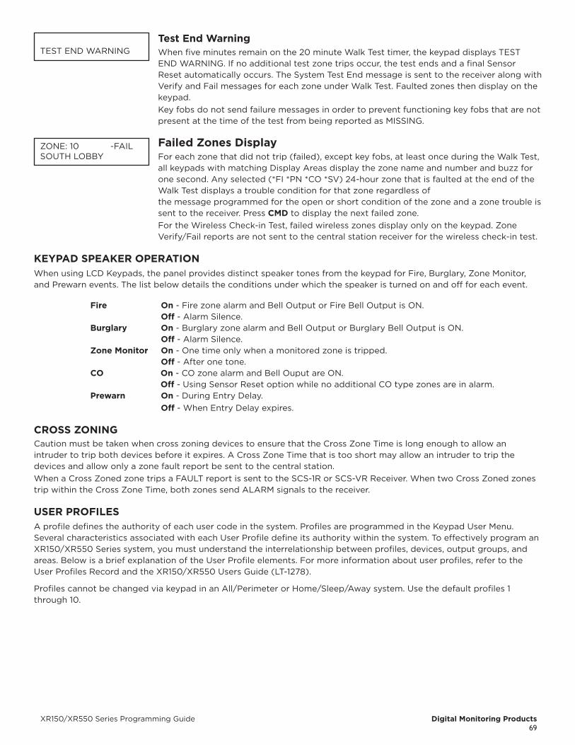
XR150/XR550 Series Programming Guide Digital Monitoring Products69
Test End WarningWhen five minutes remain on the 20 minute Walk Test timer, the keypad displays TEST END WARNING. If no additional test zone trips occur, the test ends and a final Sensor Reset automatically occurs. The System Test End message is sent to the receiver along with Verify and Fail messages for each zone under Walk Test. Faulted zones then display on the keypad.Key fobs do not send failure messages in order to prevent functioning key fobs that are not present at the time of the test from being reported as MISSING.
Failed Zones Display For each zone that did not trip (failed), except key fobs, at least once during the Walk Test,
all keypads with matching Display Areas display the zone name and number and buzz for one second. Any selected (*FI *PN *CO *SV) 24-hour zone that is faulted at the end of the Walk Test displays a trouble condition for that zone regardless of the message programmed for the open or short condition of the zone and a zone trouble is sent to the receiver. Press CMD to display the next failed zone.For the Wireless Check-in Test, failed wireless zones display only on the keypad. Zone Verify/Fail reports are not sent to the central station receiver for the wireless check-in test.
KEYPAD SPEAKER OPERATIONWhen using LCD Keypads, the panel provides distinct speaker tones from the keypad for Fire, Burglary, Zone Monitor, and Prewarn events. The list below details the conditions under which the speaker is turned on and off for each event.
Fire On - Fire zone alarm and Bell Output or Fire Bell Output is ON. Off - Alarm Silence.burglary On - Burglary zone alarm and Bell Output or Burglary Bell Output is ON. Off - Alarm Silence.Zone Monitor On - One time only when a monitored zone is tripped. Off - After one tone.CO On - CO zone alarm and Bell Ouput are ON. Off - Using Sensor Reset option while no additional CO type zones are in alarm.Prewarn On - During Entry Delay. Off - When Entry Delay expires.
CROSS ZONINGCaution must be taken when cross zoning devices to ensure that the Cross Zone Time is long enough to allow an intruder to trip both devices before it expires. A Cross Zone Time that is too short may allow an intruder to trip the devices and allow only a zone fault report be sent to the central station.When a Cross Zoned zone trips a FAULT report is sent to the SCS-1R or SCS-VR Receiver. When two Cross Zoned zones trip within the Cross Zone Time, both zones send ALARM signals to the receiver.
USER PROFILESA profile defines the authority of each user code in the system. Profiles are programmed in the Keypad User Menu. Several characteristics associated with each User Profile define its authority within the system. To effectively program an XR150/XR550 Series system, you must understand the interrelationship between profiles, devices, output groups, and areas. Below is a brief explanation of the User Profile elements. For more information about user profiles, refer to the User Profiles Record and the XR150/XR550 Users Guide (LT-1278).
Profiles cannot be changed via keypad in an All/Perimeter or Home/Sleep/Away system. Use the default profiles 1 through 10.
TEST END WARNING
ZONE: 10 -FAILSOUTH LOBBY
Digital Monitoring Products XR150/XR550 Series Programming Guide70
Profile Number - Each profile may be assigned a unique number from 1 to 99.
Profile Name - Each profile may be assigned a 32-character name. The Profile Number is the default name.
Area Number - Each profile may be assigned specific areas of the system for arming and disarming. When creating profiles 1 to 98, NO areas are assigned by default. The default for profile 99 is ALL areas assigned. Profile 99 is preprogrammed in the system at the factory.
Access Area Number - Each profile may be assigned door access area assignments. Default for profile 1 to 98 is NO areas assigned. Default for profile 99 is ALL areas assigned. Profile 99 is preprogrammed at the factory.
Output Group Assignment - Each profile may be assigned an output group number from 1 to 10. Default for profile 1 to 98 is NO output group assigned. Default for profile 99 is output group 10. Your system may by programmed to turn on an output group at certain keypads when door access occurs.
User Menu Assignments - Each user profile may have any of the menus assigned to it as shown in the following User Profile Record. The User Profile Record lists the user menu profile assignments and the system functions users are allowed to access based on the profile numbers assigned to their codes. Always make sure that at least one administrator in your system has a profile with all authorities and areas.
First Access/Second Access - Each profile may be assigned two schedules to allow or restrict access and disarming times.
Inactive User Code Audit - This option allows you to choose the number of days a user code can remain unused before the panel sends an Inactive User Code message to the receiver and changes the user code to inactive. The range is 0-425 days. The default is 0. This feature is only available for XR550 Series panels.
USER PROFILES RECORDThis User Profiles Record can be used as a tool when programming Devices, Profiles, Areas, and Output Groups. Because these programming options are interrelated, use this sheet to plan the system before you begin the installation and programming process.
Profi
le #
Profile
Name Arm
/Dis
arm
Are
as
Acc
ess
Are
as
Out
put
Gro
ups
Arm
Dis
arm
Ala
rm S
ilenc
e
Sens
or R
eset
Lock
dow
n
Doo
r Lo
ck/U
nloc
k
Doo
r A
cces
s
Arm
ed A
rea
Out
puts
On/
Off
Zone
Sta
tus
Bypa
ss Z
ones
Zone
Mon
itor
Syst
em S
tatu
s
Syst
em T
est
Use
r Pr
ofile
s
Use
r Co
des
Exte
nd S
ched
ules
Sche
dule
sTi
me
Dis
play
Eve
nts
Serv
ice
Requ
est
Fire
Dri
ll
Tem
p U
ser
Code
Ant
i-pa
ssba
ck
Firs
t Acc
ess,
1-9
9
Seco
nd A
cces
s, 1
-99
Third
Acc
ess,
1-9
9
Four
th A
cces
s, 1
-99
Fifth
Acc
ess,
1-9
9
Sixt
h Ac
cess
, 1-9
9
Seve
nth
Acce
ss, 1
-99
Eigh
th A
cces
s, 1
-99
Re A
rm D
elay
Easy
Arm
/Dis
arm
Sec
Lang
uage
Card
Plu
s Pi
n
Wi-
Fi S
etup
Tech
nici
an U
ser
Inac
tive
Use
r
Aud
it D
ays
0-42
5
Dua
l Aut
hori
ty
WIRELESS CHECK-IN AND SUPERVISION DEFINITIONSDMP 1100 Series Supervision Time ExplainedThe supervision time programmed for DMP 1100 Series wireless is the number of minutes that must elapse before a transmitter missing message is generated for a transmitter that is not sending its automatically generated supervision message. The supervision time is programmable to 3, 60, 240 minutes. Selecting 0 (zero) disables supervision time.
XR150/XR550 Series Programming Guide Digital Monitoring Products71
ZONE TYPE DESCRIPTIONSThis section describes applications for the default Keypad and LX-Bus zone types in Zone Information programming.
-- (Blank Zone)Customizable zone type. By default, no actions are programmed to occur with Blank Zone. A zone name must be entered to use this zone type: This zone type is not the same as an *UNUSED* zone.
NT (Night Zone)Controlled instant zone used for perimeter doors and windows and interior devices such as PIRs and Glassbreak detectors.
DY (Day zone)Used for emergency doors or fire doors to sound the keypad buzzer and display the zone name when the zone is faulted. Day zones also send alarm reports to the receiver during the system armed periods.
EX (Exit zone)Initiates the entry delay timer when its assigned area is fully armed. Also, can initiate an exit delay timer to allow a user to exit an area after the arming process starts.
PN (Panic zone)Used for connecting to mechanical devices that allow a user to signal an emergency alarm. Panic zones can provide either a silent or audible alarm with or without reporting to a central station receiver.
EM (Emergency zone)These are used for reporting medical or other non-panic emergencies to the central station receiver.
SV (Supervisory zone)Used to provide 24-hour zone supervision to devices associated with fire systems. Typical applications are tamper switches on Post Indicator Valves (PIVs), gate valves, and low and high temperature gauges.
FI (Fire zone)Used for any type of powered or mechanical fire detection device. Typical applications are for smoke detectors, sprinkler flowswitches, manual pull stations, and beam detectors. Retard, cross zoning, and presignal options are available for the Fire zone type.
Digital Monitoring Products XR150/XR550 Series Programming Guide72
FV (Fire Verify zone)Used primarily for smoke detector circuits to verify the existence of an actual fire condition. When a Fire Verify zone initiates an alarm, the panel performs a Fire Reset. If any Fire Verify zone initiates an alarm within 120 seconds after the reset, an alarm is indicated. If an alarm is initiated after 120 seconds, the cycle repeats.
A1 and A2 (Auxiliary 1 and Auxiliary 2)These zones are similar to a Night zone and are typically used to protect restricted areas within a protected premises.
AR (Arming zone)This zone allows you to connect a keyswitch to a zone and use it to arm and disarm one or more areas.
CO (Carbon Monoxide) This output turns on any time a Carbon Monoxide Zone (CO) is placed in alarm. The output is turned off using Sensor Reset option while no additional CO type zones are in alarm.
DB (Doorbell) This zone type is intended for use for zones that are assigned to doorbells.
XR150/XR550 Series Programming Guide Digital Monitoring Products73
COMMON KEYPAD MESSAGESThere are several common keypad messages that the keypad displays to inform the technician and end-user. The common messages are described below. Possible solutions are also provided.
Message Meaning Possible Solutions
INVALID AREA The user has attempted a door access for an area they are not assigned.
Change the user access areas if access to the area is needed. If access is not needed, the user cannot enter the area.
INVALID CODE The user code you entered is not recognized by the system. Check the user code and try again.
INVALID PROFILE A user attempted a function that is outside of the assigned profile. Check the user profile settings.
INVALID TIME A user code assigned to a specific schedule has entered outside of the valid schedule. See Schedules and User Codes.
ENTER 2ND CODE The area you are attempting to disarm or access is a Two Man Area.
A second and different user code must be entered.
CLOSING TIME The scheduled has expired but the area is not armed.
Users still on the premise should arm the system or extend the schedule to a later time.
LATE TO CLOSE The system was not armed at its scheduled closing time.
Users still on the premise should arm the system or extend the schedule to a later time.
FAILED TO EXITA user assigned the anti-passback option has attempted to re-enter an area from which they did not exit properly.
The user must exit the area through the proper door. If not possible, your system administrator should select the Forgive option in the User Codes menu.
AC TROUBLE The system AC is low or missing. Check that all AC connections are good.
BATTERY TROUBLE The System battery is either low or missing. Check that the battery connections are good and the battery is still good.
PHONE LINE 1 TROUBLE
There is trouble with the phone line supervision. Plug in the phone line.
SYSTEM TROUBLE or SERVICE REQUIRED
There is a problem with one or more components in the system.
Make sure the RESET jumper is removed from the panel. Make sure there is not a short or open condition on the green data wire to the keypad. You may also need to check that all of the keypads and expansion modules on the bus are good.
SYSTEM BUSY The system is performing another task with a higher priority.
Wait a few moments for the system to complete the task. Make sure the RESET jumper is not on the panel. If the message displays for a long period of time, the processor could be locked up.
4-WIRE BUS TROUBLE
There is not a supervised device on the bus. Program a device to be supervised.
There is low voltage or an open yellow wire. Make sure all wires are connected.
Two devices share the same address. Program one of the devices to a unique address.
TRANSMIT FAILThe panel has attempted to communicate with the central station 10 times and has not succeeded.
Verify your communication type, account number, and phone number. Make sure the telephone line is connected and working properly.
NON-POLLED ADDRESS
The device is not set to DOOR, KEYPAD or FIRE in Device Setup during programming.
Program the device as DOOR, KEYPAD or FIRE in Device Setup.
ENTER CODE (to enter Programming)
A lockout code has been programmed for the panel. Enter the lockout code.
WIRELESS TROUBLE
The panel is unable to communicate with the wireless receiver.
Verify the receiver is properly connected to the panel. Verify the correct House Code is programmed in System Options. Satisfy the front and/or rear tamper.The wireless receiver’s tamper may be faulted.
Digital Monitoring Products XR150/XR550 Series Programming Guide74
AREA ACCOUNT NUMbER MESSAGESXR150/XR550 systems send an area account number instead of the system account number with the following panel messages/events based on the area assigned to the zone that initiated the alarm:
• WARNING: Alarm Bell Silenced (S34)
• Abort Signal Received (S45)
• Cancel Signal Received (S49)
• ALERT: System Recently Armed (S78)
• ALERT: Exit Error (S80)
• ALARM: Verify Signal Received (S96) (not currently sent on area arming systems)
• The panel has always sent the area account number for the following messages:
• Zone event messages for all non-24 hour zones assigned to an area
• Arming
• Disarming
The panel sends the following messages using the area account number based on the lowest area number in Display Areas programming from the keypad being used:
• User Code Add/Change/Delete
• Door Access/Denied
• User 1 Ambush and Early Morning Ambush
• System Test Begin/End
• Unauthorized Entry
• Service Code and Service Request
The panel sends the following messages using the area account number based on the area number:
• Late to Arm for area schedules

CERTIFICATIONSCalifornia State Fire Marshal (CSFM)FCC Part 15FCC Part 68 Registration ID CCKAL00BXR550New York City (FDNY COA #6167)NIST AES Algorithm Certificate #2350 128-bitNIST AES Algorithm Certificate #2595 256-bitSIA Meets ANSI/SIA CP-01-2010 False Alarm
ReductionUnderwriters Laboratory (UL) Listed
• ANSI/UL 294 Access Control System Units• ANSI/UL 1023 Household Burglar• ANSI/UL 1076 Proprietary Burglar• ANSI/UL 1610 Central Station Burglar• ANSI/UL 1635 Digital Burglar• ANSI/UL 985 Household Fire Warning• ANSI/UL 864 Fire Protective Signaling 9th
EditionCompatible with Devices Listed for:
• ANSI/UL 268 Smoke-Automatic Fire Detectors
• ANSI/UL 346 Waterflow Indicators for Fire Protective Signaling Systems
• ANSI/UL 636 Holdup Alarm Units and Systems Accessory UL Bank, Safe, and Vault
• UL Standard Line Security• UL Encrypted Standard Line Security
EXPORT CONTROL The XR550 with encryption uses AES encryption
and any export beyond the United States must be in accordance with Export Administration Regulations.
Designed, engineered, and manufactured using U.S. and global
components in Springfield, MO. © 2021 Digital Monitoring Products, Inc.
LT-1232 21522 1.01
I N T R U S I O N F I R E A C C E S S N E T W O R K2500 North Partnership BoulevardSpringfield, Missouri 65803-8877
888.436.7832 | DMP.com


