136
Programming Guide VLT ® Midi Drive FC 280 vlt-drives.danfoss.com


Contents
1 Introduction 3
1.1 How to Read This Programming Guide 3
1.2 Definitions 4
1.2.1 Frequency Converter 4
1.2.2 Input 4
1.2.3 Motor 4
1.2.4 References 5
1.3 Electrical Wiring - Control Cables 7
2 Safety 10
2.1 Safety Symbols 10
2.2 Qualified Personnel 10
2.3 Safety Precautions 10
3 Programming 12
3.1 Local Control Panel Operation 12
3.2 Basic Programming 20
4 Parameter Descriptions 23
4.1 Parameters: 0-** Operation and Display 23
4.2 Parameters: 1-** Load and Motor 31
4.3 Parameters: 2-** Brakes 41
4.4 Parameters: 3-** Reference/Ramps 43
4.5 Parameters: 4-** Limits/Warnings 49
4.6 Parameters: 5-** Digital In/Out 52
4.7 Parameters: 6-** Analog In/Out 62
4.8 Parameters: 7-** Controllers 66
4.9 Parameters: 8-** Communications and Options 71
4.10 Parameters: 9-** PROFIdrive 75
4.11 Parameters: 10-** CAN Fieldbus 75
4.12 Parameters: 12-** Ethernet 75
4.13 Parameters: 13-** Smart Logic Control 76
4.14 Parameters: 14-** Special Functions 82
4.15 Parameters: 15-** Drive Information 88
4.16 Parameters: 16-** Data Readouts 90
4.17 Parameters: 18-** Data Readouts 2 94
4.18 Parameters: 21-** Ext. Closed Loop 95
4.19 Parameters: 22-** Application Functions 96
4.20 Parameters: 30-** Special Features 98
4.21 Parameters: 32-** Motion Control Basic Settings 98
Contents Programming Guide
MG07C202 Danfoss A/S © 03/2016 All rights reserved. 1

4.22 Parameters: 33-** Motion Control Adv. Settings 99
4.23 Parameters: 34-** Motion Control Data Readouts 100
4.24 Parameters: 37-** Application Settings 101
5 Parameter Lists 103
5.1 Introduction 103
5.2 Parameter Lists 106
6 Troubleshooting 123
6.1 Warnings and Alarms 123
Index 131
Contents VLT® Midi Drive FC 280
2 Danfoss A/S © 03/2016 All rights reserved. MG07C202

1 Introduction
1.1 How to Read This Programming Guide
1.1.1 Purpose of the Manual
This programming guide provides information aboutcontrolling the frequency converter, accessing parameters,programming, and troubleshooting.The programming guide is intended for use by qualifiedpersonnel who are familiar with the VLT® Midi Drive FC280 frequency converter.Read the instructions before programming and follow theprocedures in this manual.VLT® is a registered trademark.
1.1.2 Additional Resources
Additional resources include:• VLT® Midi Drive FC 280 Operating Guide, provides
the necessary information for getting thefrequency converter up and running.
• VLT® Midi Drive FC 280 Design Guide, providesdetailed technical information about thefrequency converter, customer design, andapplications.
• VLT® Midi Drive FC 280 Service Guide, providesinformation to Danfoss authorized, qualifiedtechnicians on how to service the FC 280frequency converters.
Contact the local Danfoss supplier or go todrives.danfoss.com/knowledge-center/technical-documen-tation/ to download the documentations.
1.1.3 Document and Software Version
This manual is regularly reviewed and updated. Allsuggestions for improvement are welcome. Table 1.1 showsthe document version and the corresponding softwareversion.
Edition Remarks Softwareversion
MG07C2 Update due to new softwareversion release.
1.1
Table 1.1 Document and Software Version
AC Alternating current
AEO Automatic energy optimization
ACP Application control processor
AWG American wire gauge
AMA Automatic motor adaptation
°C Degrees Celsius
DC Direct current
EEPROMElectrically erasable programmableread-only memory
EMC Electromagnetic compatibility
EMI Electromagnetic interference
ETR Electronic thermal relay
fM,N Nominal motor frequency
FC Frequency converter
IP Ingress protection
ILIM Current limit
IINV Rated inverter output current
IM,N Nominal motor current
IVLT,MAX Maximum output current
IVLT,NRated output current supplied by thefrequency converter
Ld Motor d-axis inductance
Lq Motor q-axis inductance
LCP Local control panel
MCP Motor control processor
N.A. Not applicable
PM,N Nominal motor power
PCB Printed circuit board
PE Protective earth
PELV Protective extra low voltage
PWM Pulse width modulated
Rs Stator resistance
Regen Regenerative terminals
RPM Revolutions per minute
RFI Radio frequency interference
SCR Silicon controlled rectifier
SMPS Switch mode power supply
TLIM Torque limit
UM,N Nominal motor voltage
Xh Motor main reactance
Table 1.2 Abbreviations
Introduction Programming Guide
MG07C202 Danfoss A/S © 03/2016 All rights reserved. 3
1 1

Table 1.3 Approval and Certification
For compliance with the European Agreement concerningInternational Carriage of Dangerous Goods by InlandWaterways (ADN), refer to ADN-compliant Installation in theVLT® Midi Drive FC 280 Design Guide.
Applied standards and compliance for STOUsing STO on terminals 37 and 38 requires fulfillment of allprovisions for safety including relevant laws, regulations,and guidelines.
The integrated STO function complies with the followingstandards:
• IEC/EN 61508: 2010 SIL2
• IEC/EN 61800-5-2: 2007 SIL2
• IEC/EN 62061: 2012 SILCL of SIL2
• IEC/EN 61326-3-1: 2008
• EN ISO 13849-1: 2008 Category 3 PL d
1.2 Definitions
1.2.1 Frequency Converter
CoastThe motor shaft is in free mode. No torque on the motor.
IVLT,MAX
Maximum output current.
IVLT,N
Rated output current supplied by the frequency converter.
UVLT,MAX
Maximum output voltage.
1.2.2 Input
Control commandsStart and stop the connected motor with LCP and digitalinputs.Functions are divided into 2 groups.
Functions in group 1 have higher priority than functions ingroup 2.
Group 1 Precise stop, coast stop, precise stop and coaststop, quick stop, DC braking, stop, and [OFF].
Group 2 Start, pulse start, reversing, start reversing, jog,and freeze output.
Table 1.4 Function Groups
1.2.3 Motor
Motor runningTorque generated on the output shaft and speed from0 RPM to maximum speed on the motor.
fJOG
Motor frequency when the jog function is activated (viadigital terminals).
fM
Motor frequency.
fMAX
Maximum motor frequency.
fMIN
Minimum motor frequency.
fM,N
Rated motor frequency (nameplate data).
IM
Motor current (actual).
IM,N
Nominal motor current (nameplate data).
nM,N
Nominal motor speed (nameplate data).
ns
Synchronous motor speed.
ns = 2 × par . 1 − 23 × 60 spar . 1 − 39
nslip
Motor slip.
PM,N
Rated motor power (nameplate data in kW or hp).
TM,N
Rated torque (motor).
UM
Instantaneous motor voltage.
UM,N
Rated motor voltage (nameplate data).
Introduction VLT® Midi Drive FC 280
4 Danfoss A/S © 03/2016 All rights reserved. MG07C202
11

Break-away torque
175Z
A07
8.10
Pull-out
rpm
Torque
Illustration 1.1 Break-away Torque
ηVLT
The efficiency of the frequency converter is defined as theratio between the power output and the power input.
Start-disable commandA start-disable command belonging to the controlcommands in group 1. See Table 1.4 for more details.
Stop commandA stop command belonging to the control commands ingroup 1. See Table 1.4 for more details.
1.2.4 References
Analog referenceA signal transmitted to the analog inputs 53 or 54 can bevoltage or current.
Binary referenceA signal transmitted to the serial communication port.
Preset referenceA defined preset reference to be set from -100% to +100%of the reference range. Selection of 8 preset references viathe digital terminals.
Pulse referenceA pulse frequency signal transmitted to the digital inputs(terminal 29 or 33).
RefMAX
Determines the relationship between the reference input at100% full scale value (typically 10 V, 20 mA) and theresulting reference. The maximum reference value is set inparameter 3-03 Maximum Reference.
RefMIN
Determines the relationship between the reference input at0% value (typically 0 V, 0 mA, 4 mA) and the resultingreference. The minimum reference value is set inparameter 3-02 Minimum Reference.
1.2.5 Miscellaneous
Analog inputsThe analog inputs are used for controlling variousfunctions of the frequency converter.
There are 2 types of analog inputs:• Current input, 0–20 mA and 4–20 mA.
• Voltage input, 0 to +10 V DC.
Analog outputsThe analog outputs can supply a signal of 0–20 mA, or 4–20 mA.
Automatic motor adaptation, AMAThe AMA algorithm determines the electrical parametersfor the connected motor at standstill.
Brake resistorThe brake resistor is a module capable of absorbing thebrake power generated in regenerative braking. Thisregenerative brake power increases the intermediate circuitvoltage, and a brake chopper ensures that the power istransmitted to the brake resistor.
CT characteristicsConstant torque characteristics used for all applicationssuch as conveyor belts, displacement pumps, and cranes.
Digital inputsThe digital inputs can be used for controlling variousfunctions of the frequency converter.
Digital outputsThe frequency converter features 2 solid-state outputs thatcan supply a 24 V DC (maximum 40 mA) signal.
DSPDigital signal processor.
ETRElectronic thermal relay is a thermal load calculation basedon present load and time. Its purpose is to estimate themotor temperature.
FC standard busIncludes RS485 bus with FC protocol or MC protocol. See parameter 8-30 Protocol.
InitialisingIf initialising is carried out (parameter 14-22 OperationMode), the frequency converter returns to the defaultsetting.
Intermittent duty cycleAn intermittent duty rating refers to a sequence of dutycycles. Each cycle consists of an on-load and an off-loadperiod. The operation can be either periodic duty or non-periodic duty.
LCPThe local control panel makes up a complete interface forcontrol and programming of the frequency converter. Thecontrol panel is detachable and can be installed up to 3 m
Introduction Programming Guide
MG07C202 Danfoss A/S © 03/2016 All rights reserved. 5
1 1

(9.8 ft) from the frequency converter, that is, in a frontpanel with the installation kit option.
NLCPThe numerical local control panel interface for control andprogramming of the frequency converter. The display isnumerical and the panel is used to show process values.The NLCP has storing and copy functions.
lsbLeast significant bit.
msbMost significant bit.
MCMShort for mille circular mil, an American measuring unit forcable cross-section. 1 MCM = 0.5067 mm2.
On-line/off-line parametersChanges to on-line parameters are activated immediatelyafter the data value is changed. Press [OK] to activatechanges to off-line parameters.
Process PIDThe PID control maintains speed, pressure, andtemperature by adjusting the output frequency to matchthe varying load.
PCDProcess control data.
Power cycleSwitch off the mains until the display (LCP) is dark, thenturn power on again.
Power factorThe power factor is the relation between I1 and IRMS.
Power factor = 3 x U x I1 cosϕ13 x U x IRMS
cosϕ1 = 1, therefore:
Power factor = I1 x cosϕ1IRMS = I1IRMS
The power factor indicates to which extent the frequencyconverter imposes a load on the mains supply.The lower the power factor, the higher the IRMS for thesame kW performance.
IRMS = I12 + I52 + I72 + .. + In2
In addition, a high power factor indicates that the differentharmonic currents are low.The built-in DC coils produce a high power factor,minimizing the imposed load on the mains supply.
Pulse input/incremental encoderAn external, digital pulse transmitter used for feeding backinformation on motor speed. The encoder is used inapplications where great accuracy in speed control isrequired.
RCDResidual current device.
Set-upSave parameter settings in 4 set-ups. Change among the 4parameter set-ups and edit 1 set-up while this set-up isinactive.
SFAVMAcronym describing the switching pattern stator flux-oriented asynchronous vector modulation.
Slip compensationThe frequency converter compensates for the motor slip bygiving the frequency a supplement that follows themeasured motor load, keeping the motor speed almostconstant.
Smart logic control (SLC)The SLC is a sequence of user-defined actions executedwhen the associated user-defined events are evaluated astrue by the smart logic controller (parameter group 13-**Smart Logic Control).
STWStatus word.
THDTotal harmonic distortion states the total contribution ofharmonic distortion.
ThermistorA temperature-dependent resistor placed where thetemperature is monitored (frequency converter or motor).
TripA state entered in fault situations, for example, if thefrequency converter is subject to overvoltage or when it isprotecting the motor, process, or mechanism. Restart isprevented until the cause of the fault has disappeared, andthe trip state is canceled by activating reset or, sometimes,by being programmed to reset automatically. Do not usetrip for personal safety.
Trip lockA state entered in fault situations when the frequencyconverter is protecting itself and requiring physicalintervention, for example, if the frequency converter issubject to a short circuit on the output. A locked trip canonly be canceled by cutting off mains, removing the causeof the fault, and reconnecting the frequency converter.Restart is prevented until the trip state is canceled byactivating reset or, in some cases, by being programmed toreset automatically. Do not use trip lock for personal safety.
VT characteristicsVariable torque characteristics used for pumps and fans.
VVC+
If compared with standard voltage/frequency ratio control,voltage vector control (VVC+) improves the dynamics andstability, both when the speed reference is changed and inrelation to the load torque.
60° AVMRefers to the switching pattern 60° asynchronous vectormodulation.
Introduction VLT® Midi Drive FC 280
6 Danfoss A/S © 03/2016 All rights reserved. MG07C202
11

1.3 Electrical Wiring - Control Cables
1.3.1 Overview
130B
E202
.15
Powerinput
Switch modepower supply
Motor
Analog output
interface
(PNP) = Source (NPN) = Sink
ON = TerminatedOFF = Open
Brakeresistor
91 (L1/N)92 (L2/L)93 (L3)
PE
50 (+10 V OUT)
53 (A IN) **
54 (A IN)
55 (COM A IN)
0/4−20 mA
12 (+24 V OUT)
13 (+24 V OUT)
18 (D IN)
10 V DC15 mA 100 mA
+ - + -
(U) 96(V) 97
(W) 98(PE) 99
(A OUT) 42
(P RS485) 68
(N RS485) 69
(COM RS485) 61
0 V
5 V
S801
0/4−20 mA
RS485RS485
03
+10 V DC
0−10 V DC
24 V DC
02
01
24 V (NPN) 0 V (PNP)
0 V (PNP)24 V (NPN)
19 (D IN)
24 V (NPN) 0 V (PNP)27 (D IN/OUT)
24 V
0 V
0 V (PNP)24 V (NPN)
29 (D IN)
24 V (NPN) 0 V (PNP)
0 V (PNP)24 V (NPN)
33 (D IN)
32 (D IN)
38 (STO2)****
37 (STO1)****
95
P 5-00
21 O
N
(+DC/R+) 89
(R-) 81
0−10 V DC
(-DC) 88
RFI
0 V
250 V AC, 3 A
Relay 1
*
***
Illustration 1.2 Basic Wiring Schematic Drawing
A=Analog, D=Digital* Built-in brake chopper is only available on 3-phase units.** Terminal 53 can also be used as digital input.*** Switch S801 (bus terminal) can be used to enable termination on the RS485 port (terminals 68 and 69).
Introduction Programming Guide
MG07C202 Danfoss A/S © 03/2016 All rights reserved. 7
1 1

In rare cases, long control cables and analog signals resultin 50/60 Hz ground loops due to noise from mains supplycables. If this occurs, break the shield or insert a 100 nFcapacitor between shield and chassis.
Connect the digital and analog inputs and outputsseparately to the common inputs (terminal 55) of thefrequency converter to avoid that ground currents fromboth groups affect other groups. For example, switchingon the digital input could disturb the analog input signal.
Input polarity of control terminals
130B
E730
.10
12 13 18 19 27 29 32 33 55
+24
VDC
0 VD
CPNP (Source)Digital input wiring
Illustration 1.3 PNP (Source)
NPN (Sink)Digital input wiring
12 13 18 19 27 29 32 33 55
+24
VDC
0 VD
C
130B
E731
.10
Illustration 1.4 NPN (Sink)
NOTICEControl cables must be shielded/armored.
See the section Using Shielded Control Cables in the designguide for the correct termination of control cables.
130B
A68
1.10
Illustration 1.5 Grounding of Shielded/Armored Control Cables
1.3.2 Start/Stop
Terminal 18 = Parameter 5-10 Terminal 18 Digital Input [8]Start.Terminal 27 = Parameter 5-12 Terminal 27 Digital Input [0]No operation (Default coast inverse).
130B
E732
.10
12 13 18 322719 29 33
P 5-
12 [2
]
P 5-
10 [8
]
Start/Stop
+24V
Speed
Start/Stop[18]
Illustration 1.6 Start/Stop
Introduction VLT® Midi Drive FC 280
8 Danfoss A/S © 03/2016 All rights reserved. MG07C202
11

1.3.3 Pulse Start/Stop
Terminal 18 = Parameter 5-10 Terminal 18 Digital Input [9]Latched start.Terminal 27 = Parameter 5-12 Terminal 27 Digital Input [6]Stop inverse.
1312 18 19
130B
D37
0.11
322927 33
P 5
- 12
[6]
P 5
- 10[
9]
+24V
Speed
Start Stop inverse
Start (18)
Stop (27)
Illustration 1.7 Pulse Start/Stop
1.3.4 Speed Up/Down
Terminals 29/32 = Speed up/downTerminal 18 = Parameter 5-10 Terminal 18 DigitalInput [9] Start (default).
Terminal 27 = Parameter 5-12 Terminal 27 DigitalInput [19] Freeze reference.
Terminal 29 = Parameter 5-13 Terminal 29 DigitalInput [21] Speed up.
Terminal 32 = Parameter 5-14 Terminal 32 DigitalInput [22] Speed down.
FC
+24 V
+24 V
D IN
D IN
D IN
D IN
D IN
D IN
+10 VA IN
A IN
COM
A OUT
12
13
18
19
27
29
32
33
50
53
54
55
42
130B
D06
9.12
Illustration 1.8 Speed Up/Down
1.3.5 Potentiometer Reference
Voltage reference via a potentiometerReference source 1 = [1] Analog input 53 (default).
Terminal 53, low voltage = 0 V.
Terminal 53, high voltage = 10 V.
Terminal 53, low ref./feedback = 0 Hz.
Terminal 53, high ref./feedback = 50 Hz.
Parameter 6-19 Terminal 53 mode = [1] Voltage.
130B
D38
1.12
555342 54 50SpeedP 6-15
1 kΩ
+10V
/15m
A
Ref. voltageP 6-11 10V
Illustration 1.9 Potentiometer Reference
Introduction Programming Guide
MG07C202 Danfoss A/S © 03/2016 All rights reserved. 9
1 1

2 Safety
2.1 Safety Symbols
The following symbols are used in this document:
WARNINGIndicates a potentially hazardous situation that couldresult in death or serious injury.
CAUTIONIndicates a potentially hazardous situation that couldresult in minor or moderate injury. It can also be used toalert against unsafe practices.
NOTICEIndicates important information, including situations thatcan result in damage to equipment or property.
2.2 Qualified Personnel
Correct and reliable transport, storage, installation,operation, and maintenance are required for the trouble-free and safe operation of the frequency converter. Onlyqualified personnel are allowed to install or operate thisequipment.
Qualified personnel are defined as trained staff, who areauthorized to install, commission, and maintain equipment,systems, and circuits in accordance with pertinent laws andregulations. Also, the personnel must be familiar with theinstructions and safety measures described in this guide.
2.3 Safety Precautions
WARNINGHIGH VOLTAGEFrequency converters contain high voltage whenconnected to AC mains input, DC supply, or load sharing.Failure to perform installation, start-up, and maintenanceby qualified personnel can result in death or seriousinjury.
• Only qualified personnel must perform instal-lation, start-up, and maintenance.
WARNINGUNINTENDED STARTWhen the frequency converter is connected to AC mains,DC supply, or load sharing, the motor may start at anytime. Unintended start during programming, service, orrepair work can result in death, serious injury, orproperty damage. The motor can start with an externalswitch, a fieldbus command, an input reference signalfrom the LCP, via remote operation using MCT 10 Set-upSoftware, or after a cleared fault condition.
To prevent unintended motor start:• Disconnect the frequency converter from the
mains.
• Press [Off/Reset] on the LCP beforeprogramming parameters.
• Completely wire and assemble the frequencyconverter, motor, and any driven equipmentbefore connecting the frequency converter toAC mains, DC supply, or load sharing.
WARNINGDISCHARGE TIMEThe frequency converter contains DC-link capacitors,which can remain charged even when the frequencyconverter is not powered. High voltage can be presenteven when the warning LED indicator lights are off.Failure to wait the specified time after power has beenremoved before performing service or repair work canresult in death or serious injury.
• Stop the motor.
• Disconnect AC mains and remote DC-linksupplies, including battery back-ups, UPS, andDC-link connections to other frequencyconverters.
• Disconnect or lock PM motor.
• Wait for the capacitors to discharge fully. Theminimum waiting time is specified in Table 2.1.
• Before performing any service or repair work,use an appropriate voltage measuring device tomake sure that the capacitors are fullydischarged.
Safety VLT® Midi Drive FC 280
10 Danfoss A/S © 03/2016 All rights reserved. MG07C202
22

Voltage [V]Power range[kW (hp)]
Minimum waiting time(minutes)
200–240 0.37–3.7 (0.5–5) 4
380–480 0.37–7.5 (0.5–10) 4
11–22 (15–30) 15
Table 2.1 Discharge Time
WARNINGLEAKAGE CURRENT HAZARDLeakage currents exceed 3.5 mA. Failure to ground thefrequency converter properly can result in death orserious injury.
• Ensure the correct grounding of the equipmentby a certified electrical installer.
WARNINGEQUIPMENT HAZARDContact with rotating shafts and electrical equipmentcan result in death or serious injury.
• Ensure that only trained and qualified personnelperform installation, start-up, and maintenance.
• Ensure that electrical work conforms to nationaland local electrical codes.
• Follow the procedures in this guide.
CAUTIONINTERNAL FAILURE HAZARDAn internal failure in the frequency converter can resultin serious injury when the frequency converter is notproperly closed.
• Ensure that all safety covers are in place andsecurely fastened before applying power.
Safety Programming Guide
MG07C202 Danfoss A/S © 03/2016 All rights reserved. 11
2 2

3 Programming
3.1 Local Control Panel Operation
The frequency converter supports numerical local controlpanel (NLCP), graphic local control panel (GLCP), and blindcover. This section describes the operations with NLCP andGLCP.
NOTICEThe frequency converter can also be programmed fromthe MCT 10 Set-up Software on PC via RS485 communi-cation port or USB port. This software can be orderedusing code number 130B1000 or downloaded from theDanfoss website: www.danfoss.com/BusinessAreas/Drives-Solutions/softwaredownload.
3.1.1 Numeric Local Control Panel (LCP)
The numerical local control panel (NLCP) is divided into 4functional sections.
A. Numeric display.
B. Menu key.
C. Navigation keys and indicator lights (LEDs).
D. Operation keys and indicator lights (LEDs).
130B
C506
.10
Setup 1A
B
C
D
5
12
13 14 15
10
11
10
9
6
7
8
4
1
2
3
Menu
Status QuickMenu
MainMenu
HandOn
O�Reset
AutoOn
Back
OKOn
Warn
Alarm
Illustration 3.1 View of the NLCP
A. Numeric displayThe LCD display is backlit with 1 numeric line. All data isshown in the NLCP.
1 The set-up number shows the active set-up and the editset-up. If the same set-up acts as both active and edit set-up, only that set-up number is shown (factory setting).When active and edit set-up differ, both numbers areshown in the display (for example set-up 12). The numberflashing indicates the edit set-up.
2 Parameter number.
3 Parameter value.
4 Motor direction is shown at the bottom left of the display.A small arrow indicates the direction.
5 The triangle indicates whether the LCP is in Status, QuickMenu, or Main Menu.
Table 3.1 Legend to Illustration 3.1, Section A
130B
D13
5.10
Setup 1234
INDEX
AHPVkWsrpmHz%n2n1 n3
p5 p4p3 p2 p1
Illustration 3.2 Display Information
B. Menu keyTo select between Status, Quick Menu, or Main Menu,press [Menu].
C. Indicator lights (LEDs) and navigation keys
Indicator Light Function
6 On Green ON turns on when the frequencyconverter receives power from themains voltage, a DC bus terminal, or a24 V external supply.
7 Warn Yellow When warning conditions are met, theyellow WARN light turns on, and textappears in the display area identifyingthe problem.
8 Alarm Red A fault condition causes the red alarmlight to flash and an alarm text isshown.
Table 3.2 Legend to Illustration 3.1, Indicator Lights (LEDs)
Programming VLT® Midi Drive FC 280
12 Danfoss A/S © 03/2016 All rights reserved. MG07C202
33

Key Function
9 [Back] For moving to the previous step or layerin the navigation structure.
10 Arrows [▲] [▼] For switching between parameter groups,parameters, and within parameters, orincreasing/decreasing parameter values.Arrows can also be used for setting localreference.
11 [OK] Press to access parameter groups or toenable a selection.
12 [►] Press to move from left to right withinthe parameter value to change each digitindividually.
Table 3.3 Legend to Illustration 3.1, Navigation Keys
D. Operation keys and indicator lights (LEDs)
Key Function
13 Hand On Starts the frequency converter in local control.
• An external stop signal by control input orserial communication overrides the localhand on.
14 Off/Reset Stops the motor but does not remove powerto the frequency converter or resets thefrequency converter manually after a fault hasbeen cleared.
15 Auto On Puts the system in remote operational mode.
• Responds to an external start command bycontrol terminals or serial communication.
Table 3.4 Legend to Illustration 3.1, Section D
WARNINGELECTRICAL HAZARDEven after pressing the [Off/Reset] key, voltage is presentat the terminals of the frequency converter. Pressing the[Off/Reset] key does not disconnect the frequencyconverter from mains. Touching live parts can result indeath or serious injury.
• Do not touch any live parts.
3.1.2 The Right-key Function on NLCP
Press [►] to edit any of the 4 digits on the displayindividually. When pressing [►] once, the cursor moves tothe first digit, and the digit starts flashing as shown inIllustration 3.3. Press the [▲] [▼] to change the value.Pressing [►] does not change the value of the digits, ormove the decimal point.
130B
C440
.10
Setup 1
Setup 1
Setup 1
Setup 1
Setup 1
Illustration 3.3 Right-key Function
[►] can also be used for moving between parametergroups. When in Main Menu, press [►] to move to the firstparameter in the next parameter group (for example, movefrom parameter 0-03 Regional Settings [0] International to parameter 1-00 Configuration Mode [0] Open loop).
NOTICEDuring start-up, the NLCP shows the message LCP ON.When this message is no longer shown, the frequencyconverter is ready for operation. Adding or removingoptions can extend the duration of start-up.
Programming Programming Guide
MG07C202 Danfoss A/S © 03/2016 All rights reserved. 13
3 3

3.1.3 Quick Menu on NLCP
The Quick Menu gives easy access to the most frequentlyused parameters.
1. To enter Quick Menu, press [Menu] until theindicator in the display is placed above QuickMenu.
2. Press [▲] [▼] to select either QM1 or QM2, thenpress [OK].
3. Press [▲] [▼] to browse through the parameters inQuick Menu.
4. Press [OK] to select a parameter.
5. Press [▲] [▼] to change the value of a parametersetting.
6. Press [OK] to accept the change.
7. To exit, press either [Back] twice (or 3 times if inQM2 and QM3) to enter Status, or press [Menu]once to enter Main Menu.
Programming VLT® Midi Drive FC 280
14 Danfoss A/S © 03/2016 All rights reserved. MG07C202
33

130BC445.12
1-22
XXX
X V
Mot
or
nom
inal
sp
eed
QM 1
0-01
[0]
1-10
[0]
1-24
XXX
X A
Lang
uage
Mot
or Ty
pe
1-20
XXX
X kW
Mot
or p
ower
Mot
or vo
ltage
1-26
XXX
X1-
23 X
XXX
Stat
or
Mot
or fr
eque
ncy
1-25
XXX
X
1-30
XXX
X
1-39
XXX
X
1-40
XXX
X
1-37
XXX
X
1-25
XXX
X
1-24
XXX
X A
3-02
XXX
X
3-03
XXX
X
3-41
XXX
X S
3-42
XXX
X S
5-12
[2]
1-29
[1]
AMA
Back
EMF a
t 10
00 R
PM
d-ax
is
QM 2
BMS
AMS
ES
5-70
XXX
X
5-71
[0]
1-30
XXX
X
1-39
XXX
X
1-90
[0]
2-10
[0]
4-16
XXX
X %
4-17
XXX
X %
4-18
XXX
X %
1-00
[0]
1-01
[1]
1-10
[0]
1-24
XXX
X A
1-20
XXX
X kW
1-22
XXX
X V
Mot
or
nom
inal
sp
eed
Mot
or p
ower
Mot
or vo
ltage
1-26
XXX
X1-
23 X
XXX
Mot
or fr
eque
ncy
1-25
XXX
X
1-30
XXX
X
1-40
XXX
X
1-37
XXX
X
1-25
XXX
X
1-24
XXX
X A
Back
EMF a
t 10
00 R
PM
d-ax
is
1-39
XXX
X 4-19
XXX
X
4-14
XXX
X
Stat
or
QM 3
QM 4
QM 5
L10C
SFS
TBD
Mot
or
nom
inal
sp
eed
Mot
or
nom
inal
sp
eed
Mot
or cu
rrent
Mot
or co
nt.
rate
d to
rque
Resis
tanc
e (R
s)
Mot
or p
oles
indu
ctan
ce (L
d)
Asyn
chro
nous
mot
or
Mot
or cu
rrent
Min
imum
refe
renc
e
Max
imum
refe
renc
e
Ram
p 1
ram
p-up
tim
e
Ram
p 1
ram
p-do
wn
time
Term
inal
27
digi
tal in
put
Basic
mot
or se
t-up
mod
e
Mot
or co
ntro
lpr
incip
le
Mot
or ty
pe
PM m
otor
PM m
otor
Mot
orcu
rrent
Mot
or co
nt.
rate
d to
rque
Stat
or
Resis
tanc
e (R
s)
Mot
or p
oles
indu
ctan
ce (L
d)
Mot
or sp
eed
high
limit
[Hz]
Max
imum
out
put f
requ
ency
Asyn
chro
nous
mot
or
Mot
or cu
rrent
RPM
RPM
RPM
Hz
RPM
Hz Hz
Hz Hz
Hz
Adv.
mot
or se
t-up
Resis
tanc
e (R
s)
Mot
or p
oles
Mot
or th
erm
alpr
otec
tion
Brak
e fu
nctio
n
Torq
ue lim
it m
otor
mod
e
Torq
ue lim
it ge
nera
tor m
ode
Curre
nt lim
it
Enco
der s
et-u
p
Term
inal
32/
33pu
lses p
er re
volu
tion
Term
inal
32/
33en
code
r dire
ctio
n
Chan
ges m
ade
Last
10
chan
ges
Sinc
e fa
ctor
y set
ting
Alar
m lo
g
Illus
trat
ion
3.4
Qui
ck M
enu
Str
uctu
re
Programming Programming Guide
MG07C202 Danfoss A/S © 03/2016 All rights reserved. 15
3 3

3.1.4 Main Menu on NLCP
The Main Menu gives access to all parameters.
1. To enter Main Menu, press [Menu] until theindicator in the display is placed above MainMenu.
2. [▲] [▼]: Browse through the parameter groups.
3. Press [OK] to select a parameter group.
4. [▲] [▼]: Browse through the parameters in thespecific group.
5. Press [OK] to select the parameter.
6. [►] and [▲] [▼]: Set/change the parameter value.
7. Press [OK] to accept the value.
8. To exit, press either [Back] twice (or 3 times forarray parameters) to enter Main Menu, or press[Menu] once to enter Status.
See Illustration 3.5, Illustration 3.6, and Illustration 3.7 for theprinciples of changing the value of continuous,enumerated, and array parameters, respectively. Theactions in the illustrations are described in Table 3.5,Table 3.6, and Table 3.7.
130B
C446
.10
Setup 1
Setup 1
Setup 1
Setup 1
Setup 1
Setup 1
Setup 1
Setup 1
1
2
3
4
5
6
7
10
11
12
OK
OK
Back
8
Back
Setup 1
2 x
+ OK
9
OK
Illustration 3.5 Main Menu Interactions - ContinuousParameters
Programming VLT® Midi Drive FC 280
16 Danfoss A/S © 03/2016 All rights reserved. MG07C202
33

1 [OK]: The first parameter in the group is shown.
2 Press [▼] repeatedly to move down to the parameter.
3 Press [OK] to start editing.
4 [►]: First digit flashing (can be edited).
5 [►]: Second digit flashing (can be edited).
6 [►]: Third digit flashing (can be edited).
7 [▼]: Decrease the parameter value, the decimal point
changes automatically.
8 [▲]: Increase the parameter value.
9 [Back]: Cancel changes, return to 2.[OK]: Accept changes, return to 2.
10 [▲][▼]: Select parameter within the group.
11 [Back]: Remove the value and show the parameter group.
12 [▲][▼]: Select group.
Table 3.5 Changing Values in Continuous Parameters
For enumerated parameters, the interaction is similar, butthe parameter value is shown in brackets because of thedigits limitation (4 large digits) on the NLCP, and the enumcan be greater than 99. When the enum value is greaterthan 99, the LCP can only show the first part of thebracket.
130B
C447
.11
Setup 1
Setup 1
Setup 1
1
2
3
4
5
6OK
OK
Back
7
OKBack
Illustration 3.6 Main Menu Interactions - EnumeratedParameters
1 [OK]: The first parameter in the group is shown.
2 Press [OK] to start editing.
3 [▲][▼]: Change parameter value (flashing).
4 Press [Back] to cancel changes or [OK] to accept changes(return to screen 2).
5 [▲][▼]: Select a parameter within the group.
6 [Back]: Remove the value and show the parameter group.
7 [▲][▼]: Select a group.
Table 3.6 Changing Values in Enumerated Parameters
Array parameters function as follows:
130B
C448
.10
1
2
4
5
6
7
8
9
10
OK
Back
Back
Back
5 x
Setup 1
Setup 1
Setup 1
Setup 1
%INDEX
%INDEX
%INDEX
Setup 1
INDEX%
OK
OK
OK
Illustration 3.7 Main Menu Interactions - Array Parameters
1 [OK]: Show parameter numbers and the value in the firstindex.
2 [OK]: Index can be selected.
3 [▲][▼]: Select index.
4 [OK]: Value can be edited.
5 [▲][▼]: Change parameter value (flashing).
6 [Back]: Cancel changes.[OK]: Accept changes.
7 [Back]: Cancel editing index, select a new parameter.
8 [▲][▼]: Select parameter within the group.
9 [Back]: Remove parameter index value and show theparameter group.
10 [▲][▼]: Select group.
Table 3.7 Changing Values in Array Parameters
Programming Programming Guide
MG07C202 Danfoss A/S © 03/2016 All rights reserved. 17
3 3

3.1.5 GLCP Layout
The GLCP is divided into 4 functional groups (seeIllustration 3.8).
A. Display area
B. Display menu keys
C. Navigation keys and indicator lights (LEDs)
D. Operation keys and reset
130B
D59
8.10
Autoon
ResetHandon
Off
StatusQuickMenu
MainMenu
AlarmLog
Back
CancelInfoOK
Status 1(1)36.4 kW
Auto Remote Ramping
0.000
On
Alarm
Warn.
A
7.83 A799 RPM
B
C
D
53.2 %
1
2
3
4
5
6
78
9
10
11
12
13
14
15
16
17
18 19 20 21
Illustration 3.8 Graphic Local Control Panel (GLCP)
A. Display areaThe display area is activated when the frequency converterreceives power from the mains voltage, a DC bus terminal,or a 24 V DC external supply.
The information shown on the LCP can be customized foruser applications. Select options in the Quick Menu Q3-13Display Settings.
Display Parameter number Default setting
1 0-20 [1602] Reference [%]
2 0-21 [1614] Motor Current
3 0-22 [1610] Power [kW]
4 0-23 [1613] Frequency
5 0-24 [1502] kWh Counter
Table 3.8 Legend to Illustration 3.8, Display Area
B. Display menu keysMenu keys are used for menu access for parameter set-up,toggling through status display modes during normaloperation, and viewing fault log data.
Key Function
6 Status Shows operational information.
7 QuickMenu
Allows access to programming parametersfor initial set-up instructions and manydetailed application instructions.
8 Main Menu Allows access to all programmingparameters.
9 Alarm Log Shows a list of current warnings, the last 10alarms, and the maintenance log.
Table 3.9 Legend to Illustration 3.8, Display Menu Keys
C. Navigation keys and indicator lights (LEDs)Navigation keys are used for programming functions andmoving the display cursor. The navigation keys alsoprovide speed control in local operation. There are also 3frequency converter status indicator lights in this area.
Key Function
10 Back Reverts to the previous step or list in themenu structure.
11 Cancel Cancels the last change or command as longas the display mode has not changed.
12 Info Press for a definition of the function beingshown.
13 Navigationkeys
To move between items in the menu, use the4 navigation keys.
14 OK Press to access parameter groups or toenable a selection.
Table 3.10 Legend to Illustration 3.8, Navigation Keys
Indicator Light Function
15 On Green ON turns on when the frequencyconverter receives power from themains voltage, a DC bus terminal,or a 24 V external supply.
16 Warn Yellow When warning conditions are met,the yellow WARN light turns on,and text appears in the displayarea identifying the problem.
17 Alarm Red A fault condition causes the redalarm light to flash, and an alarmtext is shown.
Table 3.11 Legend to Illustration 3.8, Indicator Lights (LEDs)
Programming VLT® Midi Drive FC 280
18 Danfoss A/S © 03/2016 All rights reserved. MG07C202
33

D. Operation keys and resetOperation keys are at the bottom of the LCP.
Key Function
18 Hand On Starts the frequency converter in hand-onmode.
• An external stop signal by control inputor serial communication overrides thelocal hand on.
19 Off Stops the motor but does not remove powerto the frequency converter.
20 Auto On Puts the system in remote operational mode.
• Responds to an external start commandby control terminals or serial communi-cation.
21 Reset Resets the frequency converter manuallyafter a fault has been cleared.
Table 3.12 Legend to Illustration 3.8, Operation Keys and Reset
NOTICETo adjust the display contrast, press [Status] and the[▲]/[▼] keys.
3.1.6 Parameter Settings
Establishing the correct programming for applicationsoften requires setting functions in several relatedparameters. Details for parameters are provided inchapter 4 Parameter Descriptions.
Programming data is stored internally in the frequencyconverter.
• For back-up, upload data into the LCP memory.
• To download data to another frequencyconverter, connect the LCP to that unit anddownload the stored settings.
• Restoring factory default settings does notchange data stored in the LCP memory.
3.1.7 Changing Parameter Settings withGLCP
Access and change parameter settings from the QuickMenu or from the Main Menu. The Quick Menu only givesaccess to a limited number of parameters.
1. Press [Quick Menu] or [Main Menu] on the LCP.
2. Press [▲] [▼] to browse through the parametergroups, press [OK] to select a parameter group.
3. Press [▲] [▼] to browse through the parameters,press [OK] to select a parameter.
4. Press [▲] [▼] to change the value of a parametersetting.
5. Press [◄] [►] to shift digit when a decimalparameter is in the editing state.
6. Press [OK] to accept the change.
7. Press either [Back] twice to enter Status, or press[Main Menu] once to enter the Main Menu.
View changesQuick Menu Q5 - Changes Made lists all parameterschanged from default settings.
• The list only shows parameters, which have beenchanged in the current edit set-up.
• Parameters which have been reset to defaultvalues are not listed.
• The message Empty indicates that no parametershave been changed.
3.1.8 Uploading/Downloading Data to/fromthe GLCP
1. Press [Off] to stop the motor before uploading ordownloading data.
2. Press [Main Menu] parameter 0-50 LCP Copy andpress [OK].
3. Select [1] All to LCP to upload data to the LCP orselect [2] All from LCP to download data from theLCP.
4. Press [OK]. A progress bar shows the uploading ordownloading progress.
5. Press [Hand On] or [Auto On] to return to normaloperation.
3.1.9 Restoring Default Settings with GLCP
NOTICERisk of losing programming, motor data, localization, andmonitoring records by restoration of default settings. Toprovide a back-up, upload data to the LCP before initiali-zation.
Restoring the default parameter settings is done by initiali-zation of the frequency converter. Initialization is carriedout through parameter 14-22 Operation Mode(recommended) or manually. Initialization does not resetthe settings for parameter 1-06 Clockwise Direction.
• Initialization using parameter 14-22 OperationMode does not reset frequency converter settings,such as operating hours, serial communication
Programming Programming Guide
MG07C202 Danfoss A/S © 03/2016 All rights reserved. 19
3 3

selections, fault log, alarm log, and othermonitoring functions.
• Manual initialization erases all motor,programming, localization, and monitoring dataand restores factory default settings.
Recommended initialization procedure, viaparameter 14-22 Operation Mode
1. Press [Main Menu] twice to access parameters.
2. Scroll to parameter 14-22 Operation Mode andpress [OK].
3. Scroll to [2] Initialisation and press [OK].
4. Remove power to the unit and wait for thedisplay to turn off.
5. Apply power to the unit.
Default parameter settings are restored during start-up.This may take slightly longer than normal.
6. Alarm 80, Drive initialised to default value is shown.
7. Press [Reset] to return to operation mode.
Manual initialization procedure1. Remove power to the unit and wait for the
display to turn off.
2. Press and hold [Status], [Main Menu], and [OK] atthe same time while applying power to the unit(approximately 5 s or until a click is heard andthe fan starts).
Factory default parameter settings are restored duringstart-up. This may take slightly longer than normal.
Manual initialization does not reset the followingfrequency converter information:
• Parameter 15-00 Operating hours
• Parameter 15-03 Power Up's
• Parameter 15-04 Over Temp's
• Parameter 15-05 Over Volt's
3.2 Basic Programming
3.2.1 Asynchronous Motor Set-up
Enter the following motor data in the listed order. Find theinformation on the motor nameplate.
1. Parameter 1-20 Motor Power.
2. Parameter 1-22 Motor Voltage.
3. Parameter 1-23 Motor Frequency.
4. Parameter 1-24 Motor Current.
5. Parameter 1-25 Motor Nominal Speed.
For optimum performance in VVC+ mode, extra motor datais required to set up the following parameters.
6. Parameter 1-30 Stator Resistance (Rs).
7. Parameter 1-31 Rotor Resistance (Rr).
8. Parameter 1-33 Stator Leakage Reactance (X1).
9. Parameter 1-35 Main Reactance (Xh).
The data is found in the motor datasheet (this data istypically not available on the motor nameplate). Run acomplete AMA using parameter 1-29 Automatic MotorAdaption (AMA) [1] Enable Complete AMA or enter theparameters manually.
Application-specific adjustment when running VVC+
VVC+ is the most robust control mode. In most situations,it provides optimum performance without furtheradjustments. Run a complete AMA for best performance.
3.2.2 PM Motor Set-up in VVC+
Initial programming steps1. Set parameter 1-10 Motor Construction to the
following options to activate PM motor operation:
1a [1] PM, non salient SPM
1b [2] PM, salient IPM, non Sat
1c [3] PM, salient IPM, Sat
2. Select [0] Open Loop in parameter 1-00 Configu-ration Mode.
NOTICEEncoder feedback is not supported for PM motors.
Programming motor dataAfter selecting 1 of the PM motor options inparameter 1-10 Motor Construction, the PM motor-relatedparameters in parameter groups 1-2* Motor Data, 1-3* Adv.Motor Data, and 1-4* Adv. Motor Data II are active.Find the information on the motor nameplate and in themotor datasheet.
Program the following parameters in the listed order:1. Parameter 1-24 Motor Current.
2. Parameter 1-26 Motor Cont. Rated Torque.
3. Parameter 1-25 Motor Nominal Speed.
4. Parameter 1-39 Motor Poles.
5. Parameter 1-30 Stator Resistance (Rs).Enter line-to-common stator winding resistance(Rs). If only line-line data is available, divide theline-line value by 2 to achieve the line-to-common (starpoint) value.It is also possible to measure the value with anohmmeter, which also takes the resistance of thecable into account. Divide the measured value by2 and enter the result.
Programming VLT® Midi Drive FC 280
20 Danfoss A/S © 03/2016 All rights reserved. MG07C202
33

6. Parameter 1-37 d-axis Inductance (Ld).Enter line-to-common direct axis inductance ofthe PM motor.If only line-to-line data is available, divide theline-line value by 2 to achieve the line-common(starpoint) value.It is also possible to measure the value with aninductance meter, which also takes theinductance of the cable into account. Divide themeasured value by 2 and enter the result.
7. Parameter 1-40 Back EMF at 1000 RPM.Enter line-to-line back EMF of PM motor at1000 RPM mechanical speed (RMS value). BackEMF is the voltage generated by a PM motorwhen no frequency converter is connected andthe shaft is turned externally. Back EMF isnormally specified for nominal motor speed or for1000 RPM measured between 2 lines. If the valueis not available for a motor speed of 1000 RPM,calculate the correct value as follows: Forexample, if back EMF at 1800 RPM is 320 V, theback EMF at 1000 RPM is:Back EMF=(Voltage/RPM)x1000=(320/1800)x1000=178.Program this value for parameter 1-40 Back EMF at1000 RPM.
Test motor operation1. Start the motor at low speed (100–200 RPM). If
the motor does not turn, check installation,general programming, and motor data.
ParkingThis function is the recommended choice for applicationswhere the motor rotates at slow speed (for example,windmilling in fan applications). Parameter 2-06 ParkingCurrent and parameter 2-07 Parking Time are adjustable.Increase the factory setting of these parameters forapplications with high inertia.
Start the motor at nominal speed. If the application doesnot run well, check the VVC+ PM settings. Table 3.13 showsrecommendations in different applications.
Application Settings
Low inertia applicationsILoad/IMotor <5
• Increase the value for parameter 1-17 Voltage filter timeconst. by factor 5–10.
• Reduce the value forparameter 1-14 Damping Gain.
• Reduce the value (<100%) forparameter 1-66 Min. Current atLow Speed.
Medium inertiaapplications50>ILoad/IMotor >5
Keep calculated values.
High inertia applicationsILoad/IMotor >50
Increase the values forparameter 1-14 Damping Gain,parameter 1-15 Low Speed Filter TimeConst., and parameter 1-16 HighSpeed Filter Time Const.
High load at low speed<30% (rated speed)
Increase the value for parameter 1-17 Voltage filter timeconst.Increase the value forparameter 1-66 Min. Current at LowSpeed (>100% for longer time canoverheat the motor).
Table 3.13 Recommendations in Different Applications
If the motor starts oscillating at a certain speed, increaseparameter 1-14 Damping Gain. Increase the value in smallsteps.
Starting torque can be adjusted in parameter 1-66 Min.Current at Low Speed. 100% provides nominal torque asstarting torque.
3.2.3 Automatic Motor Adaptation (AMA)
To optimize compatibility between the frequency converterand the motor in VVC+ mode, run AMA.
• The frequency converter builds a mathematicalmodel of the motor for regulating output motorcurrent, thus enhancing motor performance.
• Some motors may be unable to run the completeversion of the test. In that case, select [2] Enablereduced AMA in parameter 1-29 Automatic MotorAdaption (AMA).
• If warnings or alarms occur, see chapter 6.1 Warnings and Alarms.
• For best results, run this procedure on a coldmotor.
Programming Programming Guide
MG07C202 Danfoss A/S © 03/2016 All rights reserved. 21
3 3

To run AMA using the LCP1. By default parameter setting, connect terminals
12 and 27 before running AMA.
2. Enter the Main Menu.
3. Go to parameter group 1-** Load and Motor.
4. Press [OK].
5. Set motor parameters using nameplate data forparameter group 1-2* Motor Data.
6. Set motor cable length in parameter 1-42 MotorCable Length.
7. Go to parameter 1-29 Automatic Motor Adaption(AMA).
8. Press [OK].
9. Select [1] Enable complete AMA.
10. Press [OK].
11. The test runs automatically and indicates when itis complete.
Depending on the power size, the AMA takes 3–10 minutes to complete.
NOTICEThe AMA function does not cause the motor to run andit does not harm the motor.
Programming VLT® Midi Drive FC 280
22 Danfoss A/S © 03/2016 All rights reserved. MG07C202
33

4 Parameter Descriptions
4.1 Parameters: 0-** Operation and Display
0-01 Language
Select the language to be used in the display.
Option: Function:
[0] * English
[1] Deutsch
[2] Francais
[3] Dansk
[4] Spanish
[5] Italiano
0-03 Regional Settings
Option: Function:
NOTICEThis parameter cannot be adjusted whilethe motor is running.
[0] * Interna-tional
Activates parameter 1-20 Motor Power [kW] forsetting the motor power in kW and sets thedefault value of parameter 1-23 Motor Frequencyto 50 Hz.
[1] US Activates parameter 1-20 Motor Power [kW] forsetting the motor power in hp and sets thedefault value of parameter 1-23 Motor Frequencyto 60 Hz.
0-04 Operating State at Power-up (Hand)
Option: Function:
Selects the operating mode uponreconnection of the frequency converter tomains voltage after power down in hand onmode.
[0] Resume Restarts the frequency converter, maintainingthe start/stop settings (applied by [Hand On/Off]) selected before the power-down of thefrequency converter.
[1] * Forced stop,ref=old
Restarts the frequency converter with a savedlocal reference after mains voltage reappearsand after pressing [Hand On].
[2] Forced stop,ref=0
Resets the local reference to 0 uponrestarting the frequency converter.
0-06 GridType
Select the supply voltage, frequency, and type.
Option: Function:
[0] 200-240V/50Hz/IT-grid
[1] 200-240V/50Hz/Delta
[2] 200-240V/50Hz
[10] 380-440V/50Hz/IT-grid
0-06 GridType
Select the supply voltage, frequency, and type.
Option: Function:
[11] 380-440V/50Hz/Delta
[12] 380-440V/50Hz
[20] 440-480V/50Hz/IT-grid
[21] 440-480V/50Hz/Delta
[22] 440-480V/50Hz
[100] 200-240V/60Hz/IT-grid
[101] 200-240V/60Hz/Delta
[102] 200-240V/60Hz
[110] 380-440V/60Hz/IT-grid
[111] 380-440V/60Hz/Delta
[112] 380-440V/60Hz
[120] 440-480V/60Hz/IT-grid
[121] 440-480V/60Hz/Delta
[122] 440-480V/60Hz
0-07 Auto DC Braking
Option: Function:
Protective function against overvoltage at coast in ITgrid environment. This parameter is active only when[1] On is selected in this parameter, and IT-grid optionsare selected in parameter 0-06 GridType.
[0] Off This function is not active.
[1] * On This function is active.
0-10 Active Set-up
Select the set-up to control the frequency converter functions.Program parameters in set-ups 1–4. Use the factory set-up toreturn the initial state. Use multi set-up for remote control.
Option: Function:
[1] * Set-up 1
[2] Set-up 2
[3] Set-up 3
[4] Set-up 4
[9] Multi Set-up
0-11 Programming Set-up
Select the set-up to be programmed during operation; either theactive set-up or the inactive set-up. The set-up number beingedited flashes in the LCP.
Option: Function:
[1] Set-up 1
[2] Set-up 2
[3] Set-up 3
[4] Set-up 4
[9] * Active Set-up
Parameter Descriptions Programming Guide
MG07C202 Danfoss A/S © 03/2016 All rights reserved. 23
4 4

0-12 Link Setups
Option: Function:
The link ensures synchronising of the Notchangeable during operation parameter valuesenabling shift from 1 set-up to another duringoperation.
If the set-ups are not linked, a change betweenthem is not possible while the motor runs. Thusthe set-up change does not occur until themotor is coasted.
[0] Notlinked
Leaves parameters unchanged in both set-upsand cannot be changed while the motor runs.
[20] * Linked Copies Not changeable during operationparameters from 1 set-up to the other, so theyare identical in both set-ups.
0-14 Readout: Edit Set-ups / Channel
Range: Function:
0* [-2147483647 - 2147483647]
0-16 Application Selection
Option: Function:
[0] * None
[1] Simple Process Close Loop
[2] Local/Remote
[3] Speed Open Loop
[4] Simple Speed Close Loop
[5] Multi Speed
[6] OGD LA10
[7] OGD V210
0-20 Display Line 1.1 Small
Select a variable to display in line 1, left position.
Option: Function:
[0]
[37] Display Text 1
[38] Display Text 2
[39] Display Text 3
[748] PCD Feed Forward
[953] Profibus Warning Word
[1005] Readout Transmit Error Counter
[1006] Readout Receive Error Counter
[1230] Warning Parameter
[1501] Running Hours
[1502] kWh Counter
[1600] Control Word
[1601] Reference [Unit]
[1602] * Reference [%]
[1603] Status Word
[1605] Main Actual Value [%]
[1609] Custom Readout
[1610] Power [kW]
[1611] Power [hp]
[1612] Motor Voltage
0-20 Display Line 1.1 Small
Select a variable to display in line 1, left position.
Option: Function:
[1613] Frequency
[1614] Motor current
[1615] Frequency [%]
[1616] Torque [Nm]
[1618] Motor Thermal
[1620] Motor Angle
[1622] Torque [%]
[1630] DC Link Voltage
[1633] Brake Energy /2 min
[1634] Heatsink Temp.
[1635] Inverter Thermal
[1636] Inv. Nom. Current
[1637] Inv. Max. Current
[1638] SL Controller State
[1639] Control Card Temp.
[1650] External Reference
[1652] Feedback[Unit]
[1653] Digi Pot Reference
[1657] Feedback [RPM]
[1660] Digital Input
[1661] Terminal 53 Setting
[1662] Analog input 53
[1663] Terminal 54 Setting
[1664] Analog input 54
[1665] Analog output 42 [mA]
[1666] Digital Output
[1667] Pulse input 29[Hz]
[1668] Pulse Input 33 [Hz]
[1669] Pulse Output 27 [Hz]
[1671] Relay output
[1672] Counter A
[1673] Counter B
[1674] Prec. Stop Counter
[1680] Fieldbus CTW 1
[1682] Fieldbus REF 1
[1684] Comm. Option STW
[1685] FC Port CTW 1
[1686] FC Port REF 1
[1690] Alarm Word
[1691] Alarm Word 2
[1692] Warning Word
[1693] Warning Word 2
[1694] Ext. Status Word
[1695] Ext. Status Word 2
[1697] Alarm Word 3
[1890] Process PID Error
[1891] Process PID Output
[1892] Process PID Clamped Output
[1893] Process PID Gain Scaled Output
[2117] Ext. 1 Reference [Unit]
[2118] Ext. 1 Feedback [Unit]
Parameter Descriptions VLT® Midi Drive FC 280
24 Danfoss A/S © 03/2016 All rights reserved. MG07C202
44

0-20 Display Line 1.1 Small
Select a variable to display in line 1, left position.
Option: Function:
[2119] Ext. 1 Output [%]
[3401] PCD 1 Write For Application
[3402] PCD 2 Write For Application
[3403] PCD 3 Write For Application
[3404] PCD 4 Write For Application
[3405] PCD 5 Write For Application
[3406] PCD 6 Write For Application
[3407] PCD 7 Write For Application
[3408] PCD 8 Write For Application
[3409] PCD 9 Write For Application
[3410] PCD 10 Write For Application
[3421] PCD 1 Read For Application
[3422] PCD 2 Read For Application
[3423] PCD 3 Read For Application
[3424] PCD 4 Read For Application
[3425] PCD 5 Read For Application
[3426] PCD 6 Read For Application
[3427] PCD 7 Read For Application
[3428] PCD 8 Read For Application
[3429] PCD 9 Read For Application
[3430] PCD 10 Read For Application
[3450] Actual Position
[3456] Track Error
0-21 Display Line 1.2 Small
Select a variable to display in line 1, middle position.
Option: Function:
[0]
[37] Display Text 1
[38] Display Text 2
[39] Display Text 3
[748] PCD Feed Forward
[953] Profibus Warning Word
[1005] Readout Transmit Error Counter
[1006] Readout Receive Error Counter
[1230] Warning Parameter
[1501] Running Hours
[1502] kWh Counter
[1600] Control Word
[1601] Reference [Unit]
[1602] Reference [%]
[1603] Status Word
[1605] Main Actual Value [%]
[1609] Custom Readout
[1610] Power [kW]
[1611] Power [hp]
[1612] Motor Voltage
[1613] Frequency
[1614] * Motor current
[1615] Frequency [%]
[1616] Torque [Nm]
0-21 Display Line 1.2 Small
Select a variable to display in line 1, middle position.
Option: Function:
[1618] Motor Thermal
[1620] Motor Angle
[1622] Torque [%]
[1630] DC Link Voltage
[1633] Brake Energy /2 min
[1634] Heatsink Temp.
[1635] Inverter Thermal
[1636] Inv. Nom. Current
[1637] Inv. Max. Current
[1638] SL Controller State
[1639] Control Card Temp.
[1650] External Reference
[1652] Feedback[Unit]
[1653] Digi Pot Reference
[1657] Feedback [RPM]
[1660] Digital Input
[1661] Terminal 53 Setting
[1662] Analog input 53
[1663] Terminal 54 Setting
[1664] Analog input 54
[1665] Analog output 42 [mA]
[1666] Digital Output
[1667] Pulse input 29[Hz]
[1668] Pulse Input 33 [Hz]
[1669] Pulse Output 27 [Hz]
[1671] Relay output
[1672] Counter A
[1673] Counter B
[1674] Prec. Stop Counter
[1680] Fieldbus CTW 1
[1682] Fieldbus REF 1
[1684] Comm. Option STW
[1685] FC Port CTW 1
[1686] FC Port REF 1
[1690] Alarm Word
[1691] Alarm Word 2
[1692] Warning Word
[1693] Warning Word 2
[1694] Ext. Status Word
[1695] Ext. Status Word 2
[1697] Alarm Word 3
[1890] Process PID Error
[1891] Process PID Output
[1892] Process PID Clamped Output
[1893] Process PID Gain Scaled Output
[2117] Ext. 1 Reference [Unit]
[2118] Ext. 1 Feedback [Unit]
[2119] Ext. 1 Output [%]
[3401] PCD 1 Write For Application
[3402] PCD 2 Write For Application
[3403] PCD 3 Write For Application
Parameter Descriptions Programming Guide
MG07C202 Danfoss A/S © 03/2016 All rights reserved. 25
4 4

0-21 Display Line 1.2 Small
Select a variable to display in line 1, middle position.
Option: Function:
[3404] PCD 4 Write For Application
[3405] PCD 5 Write For Application
[3406] PCD 6 Write For Application
[3407] PCD 7 Write For Application
[3408] PCD 8 Write For Application
[3409] PCD 9 Write For Application
[3410] PCD 10 Write For Application
[3421] PCD 1 Read For Application
[3422] PCD 2 Read For Application
[3423] PCD 3 Read For Application
[3424] PCD 4 Read For Application
[3425] PCD 5 Read For Application
[3426] PCD 6 Read For Application
[3427] PCD 7 Read For Application
[3428] PCD 8 Read For Application
[3429] PCD 9 Read For Application
[3430] PCD 10 Read For Application
[3450] Actual Position
[3456] Track Error
0-22 Display Line 1.3 Small
Select a variable to display in line 1, right position.
Option: Function:
[0]
[37] Display Text 1
[38] Display Text 2
[39] Display Text 3
[748] PCD Feed Forward
[953] Profibus Warning Word
[1005] Readout Transmit Error Counter
[1006] Readout Receive Error Counter
[1230] Warning Parameter
[1501] Running Hours
[1502] kWh Counter
[1600] Control Word
[1601] Reference [Unit]
[1602] Reference [%]
[1603] Status Word
[1605] Main Actual Value [%]
[1609] Custom Readout
[1610] * Power [kW]
[1611] Power [hp]
[1612] Motor Voltage
[1613] Frequency
[1614] Motor current
[1615] Frequency [%]
[1616] Torque [Nm]
[1618] Motor Thermal
[1620] Motor Angle
[1622] Torque [%]
[1630] DC Link Voltage
0-22 Display Line 1.3 Small
Select a variable to display in line 1, right position.
Option: Function:
[1633] Brake Energy /2 min
[1634] Heatsink Temp.
[1635] Inverter Thermal
[1636] Inv. Nom. Current
[1637] Inv. Max. Current
[1638] SL Controller State
[1639] Control Card Temp.
[1650] External Reference
[1652] Feedback[Unit]
[1653] Digi Pot Reference
[1657] Feedback [RPM]
[1660] Digital Input
[1661] Terminal 53 Setting
[1662] Analog input 53
[1663] Terminal 54 Setting
[1664] Analog input 54
[1665] Analog output 42 [mA]
[1666] Digital Output
[1667] Pulse input 29[Hz]
[1668] Pulse Input 33 [Hz]
[1669] Pulse Output 27 [Hz]
[1671] Relay output
[1672] Counter A
[1673] Counter B
[1674] Prec. Stop Counter
[1680] Fieldbus CTW 1
[1682] Fieldbus REF 1
[1684] Comm. Option STW
[1685] FC Port CTW 1
[1686] FC Port REF 1
[1690] Alarm Word
[1691] Alarm Word 2
[1692] Warning Word
[1693] Warning Word 2
[1694] Ext. Status Word
[1695] Ext. Status Word 2
[1697] Alarm Word 3
[1890] Process PID Error
[1891] Process PID Output
[1892] Process PID Clamped Output
[1893] Process PID Gain Scaled Output
[2117] Ext. 1 Reference [Unit]
[2118] Ext. 1 Feedback [Unit]
[2119] Ext. 1 Output [%]
[3401] PCD 1 Write For Application
[3402] PCD 2 Write For Application
[3403] PCD 3 Write For Application
[3404] PCD 4 Write For Application
[3405] PCD 5 Write For Application
[3406] PCD 6 Write For Application
[3407] PCD 7 Write For Application
Parameter Descriptions VLT® Midi Drive FC 280
26 Danfoss A/S © 03/2016 All rights reserved. MG07C202
44

0-22 Display Line 1.3 Small
Select a variable to display in line 1, right position.
Option: Function:
[3408] PCD 8 Write For Application
[3409] PCD 9 Write For Application
[3410] PCD 10 Write For Application
[3421] PCD 1 Read For Application
[3422] PCD 2 Read For Application
[3423] PCD 3 Read For Application
[3424] PCD 4 Read For Application
[3425] PCD 5 Read For Application
[3426] PCD 6 Read For Application
[3427] PCD 7 Read For Application
[3428] PCD 8 Read For Application
[3429] PCD 9 Read For Application
[3430] PCD 10 Read For Application
[3450] Actual Position
[3456] Track Error
0-23 Display Line 2 Large
Select a variable for display in line 2.
Option: Function:
[0]
[37] Display Text 1
[38] Display Text 2
[39] Display Text 3
[748] PCD Feed Forward
[953] Profibus Warning Word
[1005] Readout Transmit Error Counter
[1006] Readout Receive Error Counter
[1230] Warning Parameter
[1501] Running Hours
[1502] kWh Counter
[1600] Control Word
[1601] Reference [Unit]
[1602] Reference [%]
[1603] Status Word
[1605] Main Actual Value [%]
[1609] Custom Readout
[1610] Power [kW]
[1611] Power [hp]
[1612] Motor Voltage
[1613] * Frequency
[1614] Motor current
[1615] Frequency [%]
[1616] Torque [Nm]
[1618] Motor Thermal
[1620] Motor Angle
[1622] Torque [%]
[1630] DC Link Voltage
[1633] Brake Energy /2 min
[1634] Heatsink Temp.
[1635] Inverter Thermal
[1636] Inv. Nom. Current
0-23 Display Line 2 Large
Select a variable for display in line 2.
Option: Function:
[1637] Inv. Max. Current
[1638] SL Controller State
[1639] Control Card Temp.
[1650] External Reference
[1652] Feedback[Unit]
[1653] Digi Pot Reference
[1657] Feedback [RPM]
[1660] Digital Input
[1661] Terminal 53 Setting
[1662] Analog input 53
[1663] Terminal 54 Setting
[1664] Analog input 54
[1665] Analog output 42 [mA]
[1666] Digital Output
[1667] Pulse input 29[Hz]
[1668] Pulse Input 33 [Hz]
[1669] Pulse Output 27 [Hz]
[1671] Relay output
[1672] Counter A
[1673] Counter B
[1674] Prec. Stop Counter
[1680] Fieldbus CTW 1
[1682] Fieldbus REF 1
[1684] Comm. Option STW
[1685] FC Port CTW 1
[1686] FC Port REF 1
[1690] Alarm Word
[1691] Alarm Word 2
[1692] Warning Word
[1693] Warning Word 2
[1694] Ext. Status Word
[1695] Ext. Status Word 2
[1697] Alarm Word 3
[1890] Process PID Error
[1891] Process PID Output
[1892] Process PID Clamped Output
[1893] Process PID Gain Scaled Output
[2117] Ext. 1 Reference [Unit]
[2118] Ext. 1 Feedback [Unit]
[2119] Ext. 1 Output [%]
[3401] PCD 1 Write For Application
[3402] PCD 2 Write For Application
[3403] PCD 3 Write For Application
[3404] PCD 4 Write For Application
[3405] PCD 5 Write For Application
[3406] PCD 6 Write For Application
[3407] PCD 7 Write For Application
[3408] PCD 8 Write For Application
[3409] PCD 9 Write For Application
[3410] PCD 10 Write For Application
[3421] PCD 1 Read For Application
Parameter Descriptions Programming Guide
MG07C202 Danfoss A/S © 03/2016 All rights reserved. 27
4 4

0-23 Display Line 2 Large
Select a variable for display in line 2.
Option: Function:
[3422] PCD 2 Read For Application
[3423] PCD 3 Read For Application
[3424] PCD 4 Read For Application
[3425] PCD 5 Read For Application
[3426] PCD 6 Read For Application
[3427] PCD 7 Read For Application
[3428] PCD 8 Read For Application
[3429] PCD 9 Read For Application
[3430] PCD 10 Read For Application
[3450] Actual Position
[3456] Track Error
0-24 Display Line 3 Large
Select a variable to display in line 3.
Option: Function:
[0]
[37] Display Text 1
[38] Display Text 2
[39] Display Text 3
[748] PCD Feed Forward
[953] Profibus Warning Word
[1005] Readout Transmit Error Counter
[1006] Readout Receive Error Counter
[1230] Warning Parameter
[1501] Running Hours
[1502] * kWh Counter
[1600] Control Word
[1601] Reference [Unit]
[1602] Reference [%]
[1603] Status Word
[1605] Main Actual Value [%]
[1609] Custom Readout
[1610] Power [kW]
[1611] Power [hp]
[1612] Motor Voltage
[1613] Frequency
[1614] Motor current
[1615] Frequency [%]
[1616] Torque [Nm]
[1618] Motor Thermal
[1620] Motor Angle
[1622] Torque [%]
[1630] DC Link Voltage
[1633] Brake Energy /2 min
[1634] Heatsink Temp.
[1635] Inverter Thermal
[1636] Inv. Nom. Current
[1637] Inv. Max. Current
[1638] SL Controller State
[1639] Control Card Temp.
[1650] External Reference
0-24 Display Line 3 Large
Select a variable to display in line 3.
Option: Function:
[1652] Feedback[Unit]
[1653] Digi Pot Reference
[1657] Feedback [RPM]
[1660] Digital Input
[1661] Terminal 53 Setting
[1662] Analog input 53
[1663] Terminal 54 Setting
[1664] Analog input 54
[1665] Analog output 42 [mA]
[1666] Digital Output
[1667] Pulse input 29[Hz]
[1668] Pulse Input 33 [Hz]
[1669] Pulse Output 27 [Hz]
[1671] Relay output
[1672] Counter A
[1673] Counter B
[1674] Prec. Stop Counter
[1680] Fieldbus CTW 1
[1682] Fieldbus REF 1
[1684] Comm. Option STW
[1685] FC Port CTW 1
[1686] FC Port REF 1
[1690] Alarm Word
[1691] Alarm Word 2
[1692] Warning Word
[1693] Warning Word 2
[1694] Ext. Status Word
[1695] Ext. Status Word 2
[1697] Alarm Word 3
[1890] Process PID Error
[1891] Process PID Output
[1892] Process PID Clamped Output
[1893] Process PID Gain Scaled Output
[2117] Ext. 1 Reference [Unit]
[2118] Ext. 1 Feedback [Unit]
[2119] Ext. 1 Output [%]
[3401] PCD 1 Write For Application
[3402] PCD 2 Write For Application
[3403] PCD 3 Write For Application
[3404] PCD 4 Write For Application
[3405] PCD 5 Write For Application
[3406] PCD 6 Write For Application
[3407] PCD 7 Write For Application
[3408] PCD 8 Write For Application
[3409] PCD 9 Write For Application
[3410] PCD 10 Write For Application
[3421] PCD 1 Read For Application
[3422] PCD 2 Read For Application
[3423] PCD 3 Read For Application
[3424] PCD 4 Read For Application
[3425] PCD 5 Read For Application
Parameter Descriptions VLT® Midi Drive FC 280
28 Danfoss A/S © 03/2016 All rights reserved. MG07C202
44

0-24 Display Line 3 Large
Select a variable to display in line 3.
Option: Function:
[3426] PCD 6 Read For Application
[3427] PCD 7 Read For Application
[3428] PCD 8 Read For Application
[3429] PCD 9 Read For Application
[3430] PCD 10 Read For Application
[3450] Actual Position
[3456] Track Error
0-30 Custom Readout Unit
Set a value to be shown in the LCP. The value has a linear,squared, or cubed relation to speed. This relation depends on theunit selected.
Option: Function:
[0]
[1] * %
[5] PPM
[10] 1/min
[11] RPM
[12] Pulse/s
[20] l/s
[21] l/min
[22] l/h
[23] m³/s
[24] m³/min
[25] m³/h
[30] kg/s
[31] kg/min
[32] kg/h
[33] t/min
[34] t/h
[40] m/s
[41] m/min
[45] m
[60] °C
[70] mbar
[71] bar
[72] Pa
[73] kPa
[74] m WG
[80] kW
[120] GPM
[121] gal/s
[122] gal/min
[123] gal/h
[124] CFM
[127] ft³/h
[140] ft/s
[141] ft/min
[160] °F
[170] psi
[171] lb/in2
0-30 Custom Readout Unit
Set a value to be shown in the LCP. The value has a linear,squared, or cubed relation to speed. This relation depends on theunit selected.
Option: Function:
[172] in WG
[173] ft WG
[180] HP
0-31 Custom Readout Min Value
Range: Function:
0 CustomRea-doutUnit*
[ 0 -999999.99CustomRea-doutUnit]
This parameter sets theminimum value of the customreadout (occurs at 0 speed). It isonly possible to select a valuedifferent from 0 when selecting alinear unit inparameter 0-30 Custom ReadoutUnit. For quadratic and cubicunits, the minimum value is 0.
0-32 Custom Readout Max Value
Range: Function:
100 Custom-ReadoutUnit*
[ 0.0 -999999.99CustomRea-doutUnit]
This parameter sets themaximum value to be shownwhen the motor speed hasreached the value set for parameter 4-14 Motor SpeedHigh Limit [Hz].
0-37 Display Text 1
Range: Function:
[0 - 0]
0-38 Display Text 2
Range: Function:
[0 - 0]
0-39 Display Text 3
Range: Function:
[0 - 0]
0-40 [Hand on] Key on LCP
Option: Function:
[0] Disabled Avoid accidental start of the frequency converterin hand-on mode.
[1] * Enabled [Hand On] is enabled.
0-42 [Auto on] Key on LCP
Option: Function:
[0] Disabled Avoid accidental start of the freqeuncy converterfrom LCP.
[1] * Enabled [Auto On] is enabled.
Parameter Descriptions Programming Guide
MG07C202 Danfoss A/S © 03/2016 All rights reserved. 29
4 4

0-44 [Off/Reset] Key on LCP
Option: Function:
[0] Disabled
[1] * Enabled
[7] Enable Reset Only
0-50 LCP Copy
Option: Function:
[0] * No copy No function.
[1] All to LCP Copies all parameters in all set-ups from thefrequency converter memory to the LCP. Forservice purposes, copy all parameters to theLCP after commissioning.
[2] All fromLCP
Copies all parameters in all set-ups from theLCP memory to the frequency convertermemory.
[3] Size indep.from LCP
Copies only the parameters that areindependent of the motor size. This selectioncan be used to program several frequencyconverters with the same function withoutdisturbing motor data that is already set.
0-51 Set-up Copy
Use this parameter to copy parameters between set-ups.
Option: Function:
[0] * No copy
[1] Copy from setup 1
[2] Copy from setup 2
[3] Copy from setup 3
[4] Copy from setup 4
[9] Copy from Factory setup
Parameter Descriptions VLT® Midi Drive FC 280
30 Danfoss A/S © 03/2016 All rights reserved. MG07C202
44
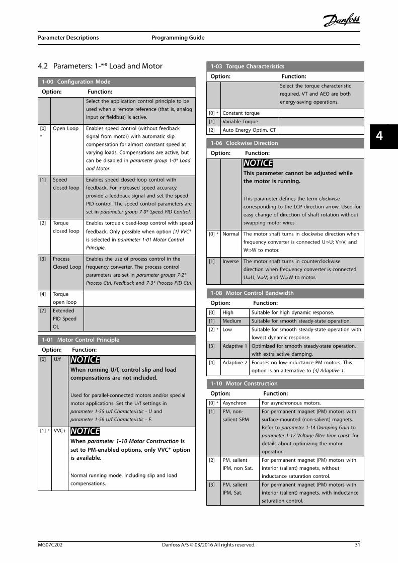
4.2 Parameters: 1-** Load and Motor
1-00 Configuration Mode
Option: Function:
Select the application control principle to beused when a remote reference (that is, analoginput or fieldbus) is active.
[0]*
Open Loop Enables speed control (without feedbacksignal from motor) with automatic slipcompensation for almost constant speed atvarying loads. Compensations are active, butcan be disabled in parameter group 1-0* Loadand Motor.
[1] Speedclosed loop
Enables speed closed-loop control withfeedback. For increased speed accuracy,provide a feedback signal and set the speedPID control. The speed control parameters areset in parameter group 7-0* Speed PID Control.
[2] Torqueclosed loop
Enables torque closed-loop control with speed
feedback. Only possible when option [1] VVC+
is selected in parameter 1-01 Motor ControlPrinciple.
[3] ProcessClosed Loop
Enables the use of process control in thefrequency converter. The process controlparameters are set in parameter groups 7-2*Process Ctrl. Feedback and 7-3* Process PID Ctrl.
[4] Torqueopen loop
[7] ExtendedPID SpeedOL
1-01 Motor Control Principle
Option: Function:
[0] U/f NOTICEWhen running U/f, control slip and loadcompensations are not included.
Used for parallel-connected motors and/or specialmotor applications. Set the U/f settings inparameter 1-55 U/f Characteristic - U andparameter 1-56 U/f Characteristic - F.
[1] * VVC+ NOTICEWhen parameter 1-10 Motor Construction isset to PM-enabled options, only VVC+ optionis available.
Normal running mode, including slip and loadcompensations.
1-03 Torque Characteristics
Option: Function:
Select the torque characteristicrequired. VT and AEO are bothenergy-saving operations.
[0] * Constant torque
[1] Variable Torque
[2] Auto Energy Optim. CT
1-06 Clockwise Direction
Option: Function:
NOTICEThis parameter cannot be adjusted whilethe motor is running.
This parameter defines the term clockwisecorresponding to the LCP direction arrow. Used foreasy change of direction of shaft rotation withoutswapping motor wires.
[0] * Normal The motor shaft turns in clockwise direction when
frequency converter is connected U⇒U; V⇒V; and
W⇒W to motor.
[1] Inverse The motor shaft turns in counterclockwisedirection when frequency converter is connected
U⇒U; V⇒V; and W⇒W to motor.
1-08 Motor Control Bandwidth
Option: Function:
[0] High Suitable for high dynamic response.
[1] Medium Suitable for smooth steady-state operation.
[2] * Low Suitable for smooth steady-state operation withlowest dynamic response.
[3] Adaptive 1 Optimized for smooth steady-state operation,with extra active damping.
[4] Adaptive 2 Focuses on low-inductance PM motors. Thisoption is an alternative to [3] Adaptive 1.
1-10 Motor Construction
Option: Function:
[0] * Asynchron For asynchronous motors.
[1] PM, non-salient SPM
For permanent magnet (PM) motors withsurface-mounted (non-salient) magnets.Refer to parameter 1-14 Damping Gain toparameter 1-17 Voltage filter time const. fordetails about optimizing the motoroperation.
[2] PM, salientIPM, non Sat.
For permanent magnet (PM) motors withinterior (salient) magnets, withoutinductance saturation control.
[3] PM, salientIPM, Sat.
For permanent magnet (PM) motors withinterior (salient) magnets, with inductancesaturation control.
Parameter Descriptions Programming Guide
MG07C202 Danfoss A/S © 03/2016 All rights reserved. 31
4 4

1-14 Damping Gain
Range: Function:
120%*
[ 0 -250 %]
The damping gain stabilizes the PM machine.The value of damping gain controls the dynamicperformance of the PM machine. High dampinggain gives high dynamic performance, and lowdamping gain gives low dynamic performance.The dynamic performance is related to themachine data and load type. If the damping gainis too high or low the control becomes unstable.
1-15 Low Speed Filter Time Const.
Range: Function:
Size related* [ 0.01 - 20s]
This time constant is used below10% rated speed. Obtain quickcontrol through a short dampingtime constant. However, if this valueis too short, the control becomesunstable.
1-16 High Speed Filter Time Const.
Range: Function:
Size related* [ 0.01 - 20s]
This time constant is used above10% rated speed. Obtain quickcontrol through a short dampingtime constant. However, if this valueis too short, the control becomesunstable.
1-17 Voltage filter time const.
Range: Function:
Sizerelated*
[ 0.001 - 1s]
Reduces the influence of highfrequency ripple and systemresonance in the calculation of supplyvoltage. Without this filter, the ripplesin the currents can distort thecalculated voltage and affect thestability of the system.
1-20 Motor Power
Option: Function:
[2] 0.12 kW - 0.16 hp
[3] 0.18 kW - 0.25 hp
[4] 0.25 kW - 0.33 hp
[5] 0.37 kW - 0.5 hp
[6] 0.55 kW - 0.75 hp
[7] 0.75 kW - 1 hp
[8] 1.1 kW - 1.5 hp
[9] 1.5 kW - 2 hp
[10] 2.2 kW - 3 hp
[11] 3 kW - 4 hp
[12] 3.7 kW - 5 hp
[13] 4 kW - 5.4 hp
[14] 5.5 kW - 7.5 hp
[15] 7.5 kW - 10 hp
1-20 Motor Power
Option: Function:
[16] 11 kW - 15 hp
[17] 15 kW - 20 hp
[18] 18.5 kW - 25 hp
[19] 22 kW - 30 hp
[20] 30 kW - 40 hp
1-22 Motor Voltage
Range: Function:
Sizerelated*
[50 - 1000V]
Enter the nominal motor voltageaccording to the motor nameplatedata. The default value corresponds tothe nominal rated output of the unit.
1-23 Motor Frequency
Range: Function:
NOTICEThis parameter cannot be adjustedwhile the motor is running.
Sizerelated*
[ 20 -500Hz]
Select the motor frequency value from themotor nameplate. For 87 Hz operation with230/440 V motors, set the value according tothe nameplate data for 230 V/50 Hz. Adapt parameter 4-14 Motor Speed High Limit [Hz] andparameter 3-03 Maximum Reference to the 87Hz application.
1-24 Motor Current
Range: Function:
Sizerelated*
[ 0.01 -10000.00 A]
Enter the nominal motor currentvalue from the motor nameplatedata. This data is used forcalculating motor torque, motorthermal protection, and so on.
1-25 Motor Nominal Speed
Range: Function:
Size related* [50 - 60000RPM]
Enter the nominal motor speedvalue from the motor nameplatedata. This data is used forcalculating automatic motorcompensations.
1-26 Motor Cont. Rated Torque
Range: Function:
Sizerelated*
[ 0.1 -10000Nm]
Enter the value from the motor nameplatedata. The default value corresponds to thenominal rated output. This parameter isavailable when parameter 1-10 MotorConstruction is set to [1] PM, non salientSPM, non Sat, [2] PM, salient IPM, non Sat, or[3] PM, salient IPM, Sat, that is, the
Parameter Descriptions VLT® Midi Drive FC 280
32 Danfoss A/S © 03/2016 All rights reserved. MG07C202
44

1-26 Motor Cont. Rated Torque
Range: Function:parameter is valid for PM, non-salient SPMand salient IPM motors only.
1-29 Automatic Motor Adaption (AMA)
Option: Function:
NOTICEThis parameter cannot be adjusted whilethe motor is running.
NOTICETerminal 27 digital input(parameter 5-12 Terminal 27 Digital Input)has coast inverse as the default setting.This setting means that AMA cannot beperformed if terminal 27 is switched off.
The AMA function optimizes dynamic motorperformance by automatically optimizing theadvanced motor parameters(parameter 1-30 Stator Resistance (Rs) toparameter 1-35 Main Reactance (Xh)) while themotor is stationary.
[0]*
Off No function.
[1] EnableCompleteAMA
Depending on the option selected inparameter 1-10 Motor Construction, the AMA isperformed on different parameters.
• If [0] Asynchron is selected, the AMA isperformed on:
- Parameter 1-30 StatorResistance (Rs).
- Parameter 1-31 Rotor Resistance(Rr).
- Parameter 1-33 Stator LeakageReactance (X1).
- Parameter 1-35 Main Reactance(Xh).
• If [1] PM, non-salient SPM, non Sat isselected, the AMA is performed on:
- Parameter 1-30 StatorResistance (Rs).
- Parameter 1-37 d-axisInductance (Ld).
• If [2] PM, salient IPM, non Sat is selected,the AMA is performed on:
1-29 Automatic Motor Adaption (AMA)
Option: Function:- Parameter 1-30 Stator
Resistance (Rs).
- Parameter 1-37 d-axisInductance (Ld).
- Parameter 1-38 q-axisInductance (Lq).
• If [3] PM, salient IPM, Sat is selected, theAMA is performed on:
- Parameter 1-30 StatorResistance (Rs).
- Parameter 1-37 d-axisInductance (Ld).
- Parameter 1-38 q-axisInductance (Lq).
- Parameter 1-44 d-axisInductance Sat. (LdSat).
- Parameter 1-45 q-axisInductance Sat. (LqSat).
[2] EnableReducedAMA
Performs a reduced AMA of the stator resistanceRs (parameter 1-30 Stator Resistance (Rs)) in thesystem only. If an LC filter is used between thefrequency converter and the motor, select thisoption.
When parameter 1-10 Motor Construction is set to optionsthat enable permanent motor mode, the only optionavailable is [1] Enable Complete AMA.
Activate the AMA function by pressing [Hand On] afterselecting [1] Enable Complete AMA or [2] Enable ReducedAMA. After a normal sequence, the display reads: Press [OK]to finish AMA. After pressing [OK], the frequency converteris ready for operation.
Parameter Descriptions Programming Guide
MG07C202 Danfoss A/S © 03/2016 All rights reserved. 33
4 4

NOTICE• For the best adaptation of the frequency
converter, run AMA on a cold motor.
• AMA cannot be performed while the motor isrunning.
NOTICEAvoid generating external torque during AMA.
NOTICEIf 1 of the settings in parameter group 1-2* Motor Data ischanged, the advanced motor parameters,parameter 1-30 Stator Resistance (Rs) to parameter 1-39 Motor Poles, return to default setting.
If LC filter is used, set the frequency converter to run in U/fcontrol mode (recommended), or perform reduced AMA inVVC+ mode. If LC filter is not used, perform complete AMA.
1-30 Stator Resistance (Rs)
Range: Function:
Sizerelated*
[ 0.0 -9999.000Ohm]
NOTICEThis parameter cannot beadjusted while the motor isrunning.
Set the stator resistance value. Enterthe value from a motor datasheetor perform an AMA on a coldmotor.
1-31 Rotor Resistance (Rr)
Range: Function:
Sizerelated*
[ 0 -9999.000Ohm]
Enter the rotor resistance value.Obtain the value from a motordatasheet or by performing an AMAon a cold motor. The default settingis calculated by the frequencyconverter from the motor nameplatedata.
1-33 Stator Leakage Reactance (X1)
Range: Function:
Sizerelated*
[ 0.0 -9999.000Ohm]
Set the stator leakage reactancevalue. Obtain the value from amotor datasheet or perform an AMAon a cold motor. The default settingis calculated by the frequencyconverter from the motor nameplatedata.
1-35 Main Reactance (Xh)
Range: Function:
Sizerelated*
[ 0.0 -9999.00Ohm]
Set the main reactance of the motor using1 of these methods:
• Run an AMA on a cold motor.The frequency convertermeasures the value from themotor.
• Enter the Xh value manually.Obtain the value from the motorsupplier.
• Use the Xh default setting. Thefrequency converter establishesthe setting based on the motornameplate data.
1-37 d-axis Inductance (Ld)
Range: Function:
Size related* [ 0 - 1000mH]
Enter the value of the d-axisinductance. Obtain the value fromthe permanent magnet motordatasheet.
1-38 q-axis Inductance (Lq)
Range: Function:
Size related* [ 0.000 -1000 mH]
NOTICEThis parameter cannot beadjusted while the motor isrunning.
Set the value of the q-axisinductance. Find the value in themotor datasheet.
1-39 Motor Poles
Range: Function:
Sizerelated*
[2 -100 ]
NOTICEThis parameter cannot be adjustedwhile the motor is running.
Enter the number of motor poles.
The motor pole value is always an evennumber, because it refers to the total polenumbers, not pairs of poles.
1-40 Back EMF at 1000 RPM
Range: Function:
Sizerelated*
[0 -9000 V]
Set the nominal back EMF for the motorwhen running at 1000 RPM.Back EMF is the voltage generated by a PMmotor when no frequency converter isconnected and the shaft is turnedexternally. Back EMF is normally specified
Parameter Descriptions VLT® Midi Drive FC 280
34 Danfoss A/S © 03/2016 All rights reserved. MG07C202
44

1-40 Back EMF at 1000 RPM
Range: Function:for nominal motor speed or for 1000 RPMmeasured between 2 lines. If the value isnot available for a motor speed of 1000RPM, calculate the correct value as follows:If back EMF is, for example, 320 V at 1800RPM, it can be calculated at 1000 RPM:ExampleBack EMF 320 V at 1800 RPM. Back EMF =(Voltage/RPM)*1000 = (320/1800)*1000 =178.
This parameter is only active whenparameter 1-10 Motor Construction is set tooptions that enable PM (permanentmagnet) motors.
NOTICEWhen using PM motors, it isrecommended to use brake resistors.
1-42 Motor Cable Length
Range: Function:
50 m* [0 - 100 m] Set the motor cable length in meters.
1-43 Motor Cable Length Feet
Range: Function:
164 ft* [0 - 328 ft] Set the motor cable length. The length unitis foot.
1-44 d-axis Inductance Sat. (LdSat)
Range: Function:
Sizerelated
[ 0 -1000mH]
This parameter is active only whenparameter 1-10 Motor Construction is set to [3]PM, salient IPM, Sat.This parameter corresponds to the saturationinductance of d-axis. The default value is thevalue set in parameter 1-37 d-axis Inductance(Ld). In most cases, do not change the defaultvalue. If the motor supplier provides thesaturation curve, enter the d-axis inductancevalue, which is 100% of the nominal current.
1-45 q-axis Inductance Sat. (LqSat)
Range: Function:
Sizerelated*
[ 0 -1000mH]
This parameter is active only whenparameter 1-10 Motor Construction is set to[3] PM, salient IPM, Sat.This parameter corresponds to the q-axissaturation inductance. The default value isthe value set in parameter 1-38 q-axisInductance (Lq). In most cases, do notchange the default value. If the motorsupplier provides the saturation curve, enter
1-45 q-axis Inductance Sat. (LqSat)
Range: Function:the q-axis inductance value, which is 100%of the nominal current.
1-46 Position Detection Gain
Range: Function:
100 %* [ 20 -200 %]
Adjusts the amplitude of the test pulseduring position detection at start. Adjustthis parameter to improve the positionmeasurement.
1-48 Current at Min Inductance for d-axis
Range: Function:
100 % [ 20 - 200 %] Use this parameter to set the inductancesaturation point.
1-49 Current at Min Inductance for q-axis
Range: Function:
100 % [ 20 -200 %]
This parameter specifies the saturation curve ofthe q-inductance values. From 20–100% of thisparameter, the inductance is linearlyapproximated due to parameter 1-38 q-axisInductance (Lq) and parameter 1-45 q-axisInductance Sat. (LqSat). These parameters arerelated to the motor nameplate load compen-sations, the application load type, and theelectronic brake function for quick stop/hold ofthe motor.
1-50 Motor Magnetisation at Zero Speed
Range: Function:
100%*
[0 -300 %]
Use this parameter along with parameter 1-52 MinSpeed Normal Magnetising [Hz] to obtain adifferent thermal load on the motor when runningat low speed.Enter a value that is a percentage of the ratedmagnetizing current. If the setting is too low, thetorque on the motor shaft may be reduced.
Magn. current
130B
B780
.10
Hz
Par.1-50 90%
Par.1-52
Illustration 4.1 Motor Magnetization
1-52 Min Speed Normal Magnetising [Hz]
Range: Function:
1 Hz* [ 0.1 - 10.0Hz]
Set the required frequency for normalmagnetizing current. Use this parameteralong with parameter 1-50 Motor Magneti-sation at Zero Speed, also see Illustration 4.1.
Parameter Descriptions Programming Guide
MG07C202 Danfoss A/S © 03/2016 All rights reserved. 35
4 4

1-55 U/f Characteristic - U
Range: Function:
Sizerelated*
[0 - 1000V]
Enter voltage at each frequency pointto manually form a U/f characteristicmatching motor. Frequency points aredefined in parameter 1-56 U/f Charac-teristic - F.
1-56 U/f Characteristic - F
Range: Function:
Sizerelated*
[ 0 -500.0Hz]
Enter frequency points to form a U/f charac-teristic matching motor. Voltage at each pointis defined in parameter 1-55 U/f Characteristic- U.
Make a U/f characteristic based on 6definable voltages and frequencies, seeIllustration 4.2.
Motor VoltagePar 1-55 [x]
Output FrequencyPar 1-56 [x]
1-55[5]
1-55[4]
1-55[3]
1-55[2]
1-55[1]1-55[0]
1-56[0]
1-56[1]
1-56[2]
1-56[3]
1-56[4]
1-56[5]
130B
A16
6.10
Illustration 4.2 Example of U/f Charac-teristic
1-60 Low Speed Load Compensation
Range: Function:
100 %* [0 -300 %]
Enter the low-speed voltage compensationvalue in percent. This parameter is used foroptimizing the low-speed load performance.This parameter is only active ifparameter 1-10 Motor Construction = [0]Asynchron.
1-61 High Speed Load Compensation
Range: Function:
100 %* [0 -300 %]
Enter the high-speed load voltage compen-sation value in percent. This parameter isused for optimizing the high-speed loadperformance. This parameter is only active ifparameter 1-10 Motor Construction = [0]Asynchron.
1-62 Slip Compensation
Range: Function:
Sizerelated*
[ -400 -399.0 %]
Enter the % value for slip compensationto compensate for tolerance in thevalue of nM,N. Slip compensation iscalculated automatically, that is, basedon the nominal motor speed nM,N.
1-63 Slip Compensation Time Constant
Range: Function:
0.1 s* [0.05 - 5 s] Enter the slip compensation reaction speed.A high value results in slow reaction, and alow value results in quick reaction. If low-frequency resonance problems occur, use alonger time setting.
1-64 Resonance Dampening
Range: Function:
100%*
[0 -500 %]
Enter the resonance dampening value. Set parameter 1-64 Resonance Dampening and parameter 1-65 Resonance Dampening TimeConstant to help eliminate high-frequencyresonance problems. To reduce resonanceoscillation, increase the value of parameter 1-64 Resonance Dampening.
1-65 Resonance Dampening Time Constant
Range: Function:
0.005 s* [ 0.001 -0.05 s]
Set parameter 1-64 Resonance Dampeningand parameter 1-65 Resonance DampeningTime Constant to help eliminate high-frequency resonance problems. Enter thetime constant that provides the bestdampening.
1-66 Min. Current at Low Speed
Range: Function:
50 %* [ 0 -120 %]
Enter the minimum motor current at lowspeed. Increasing this current improvesmotor torque at low speed.Parameter 1-66 Min. Current at Low Speed isenabled only for PM motor.
1-70 PM Start Mode
Select the PM motor start-up mode. To initialize the VVC+ controlcore for previously free-running PM motor. Active for PM motors
in VVC+ only if the motor is stopped (or running at very lowspeed).
Option: Function:
[0] * Rotor Detection Estimates the electrical angle of the rotorand uses this angle as a starting point.This option is the standard selection forindustrial applications. If flystart detectsthat the motor runs at low speed or hasstopped, the frequency converter detectsthe rotor position (the angle), and startsthe motor from that position.
[1] Parking The parking function applies DC currentacross the stator winding and rotates therotor to electrical 0 position. This option istypically for pump and fan applications. Ifflystart detects that the motor runs at low
Parameter Descriptions VLT® Midi Drive FC 280
36 Danfoss A/S © 03/2016 All rights reserved. MG07C202
44

1-70 PM Start Mode
Select the PM motor start-up mode. To initialize the VVC+ controlcore for previously free-running PM motor. Active for PM motors
in VVC+ only if the motor is stopped (or running at very lowspeed).
Option: Function:speed or has stopped, the frequencyconverter sends out a DC current to makethe motor park at an angle and then startthe motor from that position.
1-71 Start Delay
Range: Function:
0 s* [0 - 10s]
This parameter enables a delay of the startingtime. The frequency converter begins with thestart function selected in parameter 1-72 StartFunction. Set the start delay time untilacceleration is to begin.
1-72 Start Function
Option: Function:
Select the start function during start delay.This parameter is linked to parameter 1-71 StartDelay.
[0] DC Hold/delay time
Energizes motor with a DC hold current(parameter 2-00 DC Hold/Motor Preheat Current)during the start delay time.
[1] DC-Brake/delay time
Energizes motor with a DC hold current(parameter 2-01 DC Brake Current) during thestart delay time.
[2]*
Coast/delaytime
Motor coasted during the start delay time(inverter off).
[3] Start speedcw
Only possible with VVC+. Regardless of thevalue applied by the reference signal, theoutput speed applies the setting of the startspeed in parameter 1-75 Start Speed [Hz] andthe output current corresponds to the settingof the start current in parameter 1-76 StartCurrent. This function is typically used inhoisting applications without counterweightand especially in applications with a Cone-motor, where the start is clockwise, followedby rotation in the reference direction.
[4] Horizontaloperation
Only possible with VVC+.For obtaining the function described inparameter 1-75 Start Speed [Hz] and parameter 1-76 Start Current during the startdelay time. The motor rotates in the referencedirection. If the reference signal equals 0,parameter 1-75 Start Speed [Hz] is ignored andthe output speed equals 0. The output currentcorresponds to the setting of the start currentin parameter 1-76 Start Current.
1-72 Start Function
Option: Function:
[5] VVC+clockwise
The start current is calculated automatically.This function uses the start speed in the startdelay time only.
1-73 Flying Start
Option: Function:
NOTICEThis parameter cannot be changed whilethe motor is running.
NOTICETo obtain the best flying startperformance, the advanced motor data,parameter 1-30 Stator Resistance (Rs) toparameter 1-35 Main Reactance (Xh) mustbe correct.
Catches a motor which is spinning freely dueto a mains dropout.
[0]*
Disabled No function.
[1] Enabled Enables the frequency converter to catch andcontrol a spinning motor. When parameter 1-73 Flying Start is enabled, parameter 1-71 Start Delay, andparameter 1-72 Start Function have no function.
[2] EnabledAlways
Enables flying start at every start command.
[3] EnabledRef. Dir.
Enables the frequency converter to catch andcontrol a spinning motor. The searching isperformed only in the reference direction.
[4] Enab.Always Ref.Dir.
Enables flying start at every start command.The searching is performed only in thereference direction.
1-75 Start Speed [Hz]
Range: Function:
Sizerelated*
[ 0 -500.0Hz]
This parameter can be used for hoistapplications (cone rotor). Set a motor startspeed. After the start signal, the outputspeed leaps to the set value. Set the startfunction in parameter 1-72 Start Function to[3] Start speed cw, [4] Horizontal operation, or
[5] VVC+ clockwise, and set a start delay timein parameter 1-71 Start Delay.
Parameter Descriptions Programming Guide
MG07C202 Danfoss A/S © 03/2016 All rights reserved. 37
4 4

1-76 Start Current
Range: Function:
Sizerelated*
[ 0 -10000 A]
Some motors, for example cone rotormotors, need extra current/starting speedto disengage the rotor. To obtain this boost,set the required current in this parameter.Set parameter 1-72 Start Function to [3] Startspeed cw or [4] Horizontal operation, and seta start delay time in parameter 1-71 StartDelay.
1-78 Compressor Start Max Speed [Hz]
Range: Function:
0 Hz* [ 0 -500 Hz]
This parameter enables high starting torque. Thetime from the start signal is given until thespeed exceeds the speed set in this parameterbecomes a start zone. In the start zone, thecurrent limit and motoric torque limit are set tothe maximum possible value for the frequencyconverter/motor combination. The time withoutprotection from the current limit and torquelimit must not exceed the value set in parameter 1-79 Compressor Start Max Time to Trip.Otherwise, the frequency converter trips withalarm 18, Start Failed.
1-79 Compressor Start Max Time to Trip
Range: Function:
5 s* [0 -10 s]
The time from the start signal is given until thespeed exceeds the speed set inparameter 1-78 Compressor Start Max Speed [Hz]must not exceed the time set in this parameter.Otherwise, the frequency converter trips with alarm18, Start Failed. Any time set in parameter 1-71 StartDelay for use of a start function must be executedwithin the time limit.
1-80 Function at Stop
Option: Function:
Select the frequency converter function aftera stop command or after the speed is rampeddown to the settings in parameter 1-82 MinSpeed for Function at Stop [Hz].
Available selections depend on the setting inparameter 1-10 Motor Construction.
• [0] Asynchron.
- [0] Coast.
- [1] DC hold.
- [3] Pre-magnetizing.
• [1] PM, non-salient SPM, non Sat.
• [2] PM, salient IPM, non Sat.
• [3] PM, salient IPM, Sat.
1-80 Function at Stop
Option: Function:- [0] Coast.
- [1] DC hold.
[0]*
Coast Leaves the motor in free mode.
[1] DC hold /MotorPreheat
Energizes the motor with a DC hold current(see parameter 2-00 DC Hold/Motor PreheatCurrent.
[3] Pre-magnetizing
Builds up a magnetic field while the motor isstopped. This allows the motor to producetorque quickly at commands (asynchronousmotors only). This premagnetizing functiondoes not help the very first start command.Two different solutions are available to pre-magnetize the machine for the first startcommand:
1. Start the frequency converter with a0 RPM reference and wait 2–4 rotortime constants (see the equationbelow) before increasing the speedreference.
2. 2a Set parameter 1-71 StartDelay to the premagnetizetime (2–4 rotor timeconstants).
2b Set parameter 1-72 StartFunction to [0] DC hold.
2c Set the DC-hold currentmagnitude(parameter 2-00 DC Hold/Motor Preheat Current to beequal to Ipre-mag = Unom/(1.73 x Xh).
Sample rotor time constants=(Xh+X2)/(6.3*Freq_nom*Rr)1 kW=0.2 s10 kW=0.5 s100 kW=1.7 s
1-82 Min Speed for Function at Stop [Hz]
Range: Function:
0 Hz* [0 - 20 Hz] Set the output frequency at which toactivate parameter 1-80 Function at Stop.
1-83 Precise Stop Function
Option: Function:
[0]*
Precise rampstop
Only optimal when the operational speed(for example the operational speed of aconveyor belt) is constant. This is an open-loop control. Achieves high repetitiveprecision at the stopping point.
Parameter Descriptions VLT® Midi Drive FC 280
38 Danfoss A/S © 03/2016 All rights reserved. MG07C202
44

1-83 Precise Stop Function
Option: Function:
[1] Counter stopwith reset
Counts the number of pulses, typically froman encoder, and generates a stop signalafter a preprogrammed number of pulsesdefined in parameter 1-84 Precise StopCounter Value, which has been received atterminal 29 or terminal 33. This is a directfeedback with one-way closed loop control.The counter function is activated (startstiming) at the edge of the start signal(when it changes from stop to start). Aftereach precise stop, the number of pulsescounted during ramp down to 0 RPM isreset.
[2] Counter stopwithout reset
Same as [1], but the number of pulsescounted during ramp down to 0 RPM isdeducted from the counter value entered in parameter 1-84 Precise Stop Counter Value.This reset function can be used tocompensate for the extra distance doneduring ramping down, and to reduce theimpacts of gradual wear of mechanicalparts.
[3] Speedcompensatedstop
Stops at precisely the same point, regardlessof the present speed. The stop signal isdelayed internally when the present speedis lower than the maximum speed (set inparameter 4-19 Max Output Frequency). Thedelay is calculated on the basis of thereference speed of the frequency converterand not based on the actual speed. Makesure that the frequency converter hasramped up before activating the speedcompensated stop.
[4] Speedcompensatedcounter stopwith reset
Same as [3], but after each precise stop, thenumber of pulses counted during rampdown to 0 RPM is reset.
[5] Speedcompensatedcounter stopwithout reset
Same as [3], but the number of pulsescounted during ramp down to 0 RPM isdeducted from the counter value entered in parameter 1-84 Precise Stop Counter Value.This reset function can be used tocompensate for the extra distance doneduring ramping down and to reduce theimpacts of gradual wear of mechanicalparts.
1-84 Precise Stop Counter Value
Range: Function:
100000* [0 -999999999]
Enter the counter value to be used inthe integrated precise stop function in parameter 1-83 Precise Stop Function.
1-84 Precise Stop Counter Value
Range: Function:The maximum permissible frequencyat terminal 29 or 33 is 32 kHz.
1-85 Precise Stop Speed Compensation Delay
Range: Function:
10 ms* [0 - 100ms]
Enter the delay time for sensors, PLCs, and soon for use in parameter 1-83 Precise StopFunction. In speed-compensated stop mode,the delay time at different frequencies has amajor influence on the stop function.
1-88 AC Brake Gain
Range: Function:
1.4* [1.0 -2.0]
This parameter is used to set AC brake powercapability (set ramp-down time when inertia isconstant). In the condition that the DC-link voltageis not higher than DC-link voltage trip value, thegenerator torque can be adjusted with thisparameter. The higher AC brake gain is, thestronger the brake capability is. It equals to 1.0means that there is no AC brake capability.
NOTICEIf there is continuous generator torque,higher generator torque causes highermotor current, and the motor becomes hot.In this condition, the parameter 2-16 ACBrake, Max current can be used to protectthe motor from overheating.
1-90 Motor Thermal Protection
Option: Function:
[0] * No protection Continuously overloaded motor, when nowarning or trip of the frequency converteris required.
[1] Thermistorwarning
Activates a warning when the connectedthermistor in the motor reacts on a motorovertemperature.
[2] Thermistortrip
Stops (trips) the frequency converter whenthe connected thermistor in the motorreacts on a motor overtemperature.
The thermistor cut out value must be >3
kΩ.
Integrate a thermistor (PTC sensor) in themotor for winding protection.
[3] ETR warning 1 Calculates the load and activates a warningin the display when the motor isoverloaded. Program a warning signal via 1of the digital outputs.
[4] ETR trip 1 Calculates the load and stops (trips) thefrequency converter when the motor is
Parameter Descriptions Programming Guide
MG07C202 Danfoss A/S © 03/2016 All rights reserved. 39
4 4

1-90 Motor Thermal Protection
Option: Function:overloaded. Program a warning signal via 1of the digital outputs. The signal appears inthe event of a warning and if thefrequency converter trips (thermalwarning).
[22] ETR Trip -ExtendedDetection
1-93 Thermistor Source
Option: Function:
NOTICEThis parameter cannot be changedwhile the motor is running.
NOTICESet the digital input to [0] PNP - Activeat 24 V in parameter 5-00 Digital I/OMode.
Select the input to which the thermistor (PTCsensor) should be connected. An analoginput option [1] Analog Input 53 or [2] AnalogInput 54 cannot be selected if the analoginput is already in use as a reference source(selected in parameter 3-15 Reference 1 Source,parameter 3-16 Reference 2 Source, or parameter 3-17 Reference 3 Source.
[0] * None
[1] AnalogInput 53
[2] AnalogInput 54
[3] Digital input18
[4] Digital input19
[5] Digital input32
[6] Digital input33
Parameter Descriptions VLT® Midi Drive FC 280
40 Danfoss A/S © 03/2016 All rights reserved. MG07C202
44

4.3 Parameters: 2-** Brakes
2-00 DC Hold/Motor Preheat Current
Range: Function:
50 %*
[0 -160 %]
Set the holding current as a percentage of therated motor current IM,N parameter 1-24 MotorCurrent. This parameter holds the motor function(holding torque) or pre-heats the motor. Thisparameter is active if [0] DC hold is selected inparameter 1-72 Start Function, or if [1] DC hold/pre-heat is selected in parameter 1-80 Function atStop.
NOTICEThe maximum value depends on the ratedmotor current. Avoid 100% current for toolong. It may damage the motor.
2-01 DC Brake Current
Range: Function:
50%*
[0 -150 %]
NOTICEMOTOR OVERHEATINGThe maximum value depends on the ratedmotor current.To avoid motor damage caused byoverheating, do not run at 100% for toolong.
Set current as % of rated motor current, parameter 1-24 Motor Current. When speed isbelow the limit set in parameter 2-04 DC Brake CutIn Speed, or when the DC-brake inverse function isactive (in parameter group 5-1* Digital Inputs set to[5] DC-brake inverse; or via the serial port), a DC-brake current is applied on a stop command. See parameter 2-02 DC Braking Time for duration.
2-02 DC Braking Time
Range: Function:
10 s* [0 - 60 s] Set the duration of the DC-brake current set in parameter 2-01 DC Brake Current, onceactivated.
2-04 DC Brake Cut In Speed
Range: Function:
0 Hz* [ 0 - 500Hz]
This parameter is for setting the DC brakecut-in speed at which the DC brake current parameter 2-01 DC Brake Current is to beactive, with a stop command.
2-06 Parking Current
Range: Function:
100 %* [0 - 150 %] Set current as percentage of rated motorcurrent, parameter 1-24 Motor Current.
2-07 Parking Time
Range: Function:
3 s* [0.1 - 60 s] Set the duration of the parking current set inparameter 2-06 Parking Current, once activated.
2-10 Brake Function
Option: Function:
[0]*
Off No brake resistor is installed.
[1] Resistorbrake
A brake resistor is incorporated in the system fordissipating surplus brake energy as heat.Connecting a brake resistor allows a higher DC-link voltage during braking (generatingoperation). The brake resistor function is onlyactive in frequency converters with an integraldynamic brake.
[2] AC brake Improves braking without using a brake resistor.This parameter controls an overmagnetization ofthe motor when running with a generatoric load.This function can improve the OVC function.Increasing the electrical losses in the motorallows the OVC function to increase brakingtorque without exceeding the voltage limit.
NOTICEThe AC brake is not as efficient asdynamic braking with resistor.AC brake is for VVC+ mode in both openand closed loop.
2-11 Brake Resistor (ohm)
Range: Function:
Sizerelated*
[ 0 -65535Ohm]
Set the brake resistor value in Ω. Thisvalue is used for monitoring the power tothe brake resistor. Parameter 2-11 BrakeResistor (ohm) is only active in frequencyconverters with an integral dynamic brake.Use this parameter for values withoutdecimals.
2-12 Brake Power Limit (kW)
Range: Function:
Sizerelated*
[0.001 -2000kW]
Parameter 2-12 Brake Power Limit (kW) is theexpected average power dissipated in thebrake resistor over a period of 120 s. It isused as the monitoring limit forparameter 16-33 Brake Energy Average andspecifies when a warning/alarm is given.To calculate parameter 2-12 Brake PowerLimit (kW), the following formula can beused.
Pbr, avg W = Ubr2 V × tbr s
Rbr Ω × Tbr s
Parameter Descriptions Programming Guide
MG07C202 Danfoss A/S © 03/2016 All rights reserved. 41
4 4

2-12 Brake Power Limit (kW)
Range: Function:Pbr,avg is the average power dissipated inthe brake resistor. Rbr is the resistance ofthe brake resistor. tbr is the active breakingtime within the 120 s period Tbr.Ubr is the DC voltage where the brakeresistor is active. For T4 units, the DCvoltage is 770 V, which can be reduced byparameter 2-14 Brake voltage reduce.
NOTICEIf Rbr is not known or if Tbr is differentfrom 120 s, the practical approach isto run the brake application, read outparameter 16-33 Brake Energy Average,and then enter this value + 20% inparameter 2-12 Brake Power Limit(kW).
2-14 Brake voltage reduce
Range: Function:
0 V* [ 0 - 70 V] Setting this parameter may change the brakeresistor (parameter 2-11 Brake Resistor (ohm)).
2-16 AC Brake, Max current
Range: Function:
100 %* [0 -160 %]
Enter the maximum allowed current whenusing AC brake to avoid overheating ofmotor windings.
NOTICEParameter 2-16 AC Brake, Max currentis not available for all PM motors, forexample, all of the PM choices inparameter 1-10 Motor Construction.
2-17 Over-voltage Control
Option: Function:
Overvoltage control (OVC) reduces the risk ofthe frequency converter tripping due to anovervoltage on the DC link caused bygenerative power from the load.
[0] * Disabled No OVC required.
[1] Enabled(not atstop)
Activates OVC except when using a stop signalto stop the frequency converter.
[2] Enabled Activates OVC.
2-17 Over-voltage Control
Option: Function:
WARNINGPERSONAL INJURY AND EQUIPMENTDAMAGEEnabling OVC in hoisting applicationsmay lead to personal injuries andequipment damage. Do not enable OVCin such applications.
2-19 Over-voltage Gain
Range: Function:
100 %* [0 - 200 %] Select overvoltage gain.
2-20 Release Brake Current
Range: Function:
0 A* [0 - 100A]
Set the motor current for release of themechanical brake when a start condition ispresent. The upper limit is specified inparameter 16-37 Inv. Max. Current.
NOTICEWhen mechanical brake control output isselected, but no mechanical brake isconnected, the function does not work bydefault setting due to too low motorcurrent.
2-22 Activate Brake Speed [Hz]
Range: Function:
0 Hz* [0 - 400 Hz] Set the motor frequency for activation ofthe mechanical brake when a stopcondition is present.
2-23 Activate Brake Delay
Range: Function:
0 s* [0 - 5 s] Enter the brake delay time of the coast afterramp-down time. The shaft is held at zero speedwith full holding torque. Ensure that themechanical brake has locked the load before themotor enters coast mode.
Parameter Descriptions VLT® Midi Drive FC 280
42 Danfoss A/S © 03/2016 All rights reserved. MG07C202
44

4.4 Parameters: 3-** Reference/Ramps
3-00 Reference Range
Option: Function:
[0] * Min - Max Select the range of the reference signal andthe feedback signal. Signal values can bepositive only, or positive and negative.
[1] -Max -+Max
For both positive and negative values (bothdirections), relative to parameter 4-10 MotorSpeed Direction.
3-01 Reference/Feedback Unit
Option: Function:
Select the unit for process PID control referencesand feedbacks.
[0]
[1] %
[2] RPM
[3] Hz
[4] Nm
[5] PPM
[10] 1/min
[12] Pulse/s
[20] l/s
[21] l/min
[22] l/h
[23] m³/s
[24] m³/min
[25] m³/h
[30] kg/s
[31] kg/min
[32] kg/h
[33] t/min
[34] t/h
[40] m/s
[41] m/min
[45] m
[60] °C
[70] mbar
[71] bar
[72] Pa
[73] kPa
[74] m WG
[80] kW
[120] GPM
[121] gal/s
[122] gal/min
[123] gal/h
[124] CFM
[125] ft³/s
[126] ft³/min
[127] ft³/h
[130] lb/s
[131] lb/min
3-01 Reference/Feedback Unit
Option: Function:
[132] lb/h
[140] ft/s
[141] ft/min
[145] ft
[150] lb ft
[160] °F
[170] psi
[171] lb/in2
[172] in WG
[173] ft WG
[180] HP
3-02 Minimum Reference
Range: Function:
0ReferenceFeedbackUnit*
[ 0 - 4999ReferenceFeedbackUnit]
Enter the minimum reference. Theminimum reference is the lowest valueobtainable by summing all references.The minimum reference is active onlywhen parameter 3-00 Reference Range isset to [0] Min.–Max.
The minimum reference unit matches:
• The option inparameter 1-00 ConfigurationMode.
• The unit selected inparameter 3-01 Reference/Feedback Unit.
3-03 Maximum Reference
Range: Function:
Sizerelated*
[-4999.0 - 4999ReferenceFeed-backUnit]
Enter the maximum reference. Themaximum reference is the highestvalue obtainable by summing allreferences.
The maximum reference unitmatches:
• The option selected inparameter 1-00 ConfigurationMode.
• The unit selected in parameter 3-00 ReferenceRange.
3-04 Reference Function
Option: Function:
[0] * Sum Sums both external and preset referencesources.
[1] External/Preset
Use either the preset or the externalreference source. Shift between external andpreset via a command or a digital input.
Parameter Descriptions Programming Guide
MG07C202 Danfoss A/S © 03/2016 All rights reserved. 43
4 4

3-10 Preset Reference
Range: Function:
0 %* [-100 -100 %]
Enter up to 8 different preset references (0–7)in this parameter, using array programming. Forselecting dedicated references, select presetreference bit 0/1/2 [16], [17], or [18] for thecorresponding digital inputs in parameter group5-1* Digital Inputs.
3-11 Jog Speed [Hz]
Range: Function:
5 Hz* [ 0 - 500.0Hz]
The jog speed is a fixed output speed atwhich the frequency converter runs whenthe jog function is activated. See alsoparameter 3-80 Jog Ramp Time.
3-12 Catch up/slow Down Value
Range: Function:
0 %* [0 -100 %]
Enter a percentage value to be either added to ordeducted from the actual reference for catchingup or slowing down respectively. If [28] Catch up isselected via 1 of the digital inputs(parameter 5-10 Terminal 18 Digital Input toparameter 5-15 Terminal 33 Digital Input), thepercentage value is added to the total reference. If[29] Slow down is selected via 1 of the digitalinputs (parameter 5-10 Terminal 18 Digital Input toparameter 5-15 Terminal 33 Digital Input), thepercentage value is deducted from the totalreference.
3-14 Preset Relative Reference
Range: Function:
0 %* [-100 -100 %]
The actual reference, X, is increased or decreasedwith the percentage Y, set inparameter 3-14 Preset Relative Reference. Thisresults in the actual reference Z. Actual reference(X) is the sum of the inputs selected inparameter 3-15 Reference 1 Source,parameter 3-16 Reference 2 Source,parameter 3-17 Reference 3 Source, andparameter 8-02 Control Source.
RelativeZ=X+X*Y/100
Resultingactualreference
Y
X
130B
A05
9.12
Z
Illustration 4.3 Preset Relative Reference
X
100 %0-100
Z
Y
X+X*Y/100
P 3-14
130B
A27
8.10
Illustration 4.4 Actual Reference
3-15 Reference 1 Source
Option: Function:
Select the reference input to be usedfor the first reference signal. Parameter 3-15 Reference 1 Source, parameter 3-16 Reference 2 Source, and parameter 3-17 Reference 3 Source defineup to 3 different reference signals. Thesum of these reference signals definesthe actual reference.
[0] No function
[1] * Analog Input 53
[2] Analog Input 54
[7] Frequency input29
[8] Frequency input33
[11] Local busreference
[20] Digital pot.meter
[32] Bus PCD
3-16 Reference 2 Source
Option: Function:
Select the reference input to be usedfor the first reference signal. Parameter 3-15 Reference 1 Source, parameter 3-16 Reference 2 Source, and parameter 3-17 Reference 3 Source defineup to 3 different reference signals. Thesum of these reference signals definesthe actual reference.
[0] No function
[1] Analog Input 53
[2] * Analog Input 54
[7] Frequency input29
[8] Frequency input33
[11] Local busreference
Parameter Descriptions VLT® Midi Drive FC 280
44 Danfoss A/S © 03/2016 All rights reserved. MG07C202
44

3-16 Reference 2 Source
Option: Function:
[20] Digital pot.meter
[32] Bus PCD
3-17 Reference 3 Source
Option: Function:
Select the reference input to be usedfor the first reference signal. Parameter 3-15 Reference 1 Source, parameter 3-16 Reference 2 Source, and parameter 3-17 Reference 3 Sourcedefine up to 3 different referencesignals. The sum of these referencesignals defines the actual reference.
[0] No function
[1] Analog Input 53
[2] Analog Input 54
[7] Frequency input29
[8] Frequency input33
[11] * Local busreference
[20] Digital pot.meter
[32] Bus PCD
3-18 Relative Scaling Reference Resource
Option: Function:
NOTICEThis parameter cannot be adjustedwhile the motor is running.
Select a variable value to be added to thefixed value (defined in parameter 3-14 Preset Relative Reference).The sum of the fixed and variable values(labeled Y in Illustration 4.5) is multipliedby the actual reference (labeled X inIllustration 4.5). This product is thenadded to the actual reference (X+X*Y/100)to give the resulting actual reference.
RelativeZ=X+X*Y/100
Resultingactualreference
Y
X
130B
A05
9.12
Z
Illustration 4.5 Resulting ActualReference
[0] * No function
[1] Analog Input 53
[2] Analog Input 54
[7] Frequency input29
3-18 Relative Scaling Reference Resource
Option: Function:
[8] Frequency input33
[11] Local busreference
3-40 Ramp 1 Type
Option: Function:
Select the ramp type, depending onrequirements for acceleration/deceleration. Alinear ramp gives constant acceleration duringramping. A sine-2 ramp gives non-linearacceleration.
[0] * Linear
[1] SineRamp
[2] Sine 2Ramp
S-ramp based on the values set inparameter 3-41 Ramp 1 Ramp Up Time andparameter 3-42 Ramp 1 Ramp Down Time.
3-41 Ramp 1 Ramp Up Time
Range: Function:
Sizerelated*
[0.01 -3600 s]
Enter the ramp-up time, that is theacceleration time from 0 RPM to thesynchronous motor speed nS. Select a ramp-up time such that the output current doesnot exceed the current limit in parameter 4-18 Current Limit during ramping.The value 0.00 corresponds to 0.01 s inspeed mode. See ramp-down time inparameter 3-42 Ramp 1 Ramp Down Time.
Par . 3 − 41 = tacc s x ns RPM ref RPM
3-42 Ramp 1 Ramp Down Time
Range: Function:
Sizerelated*
[0.01 -3600 s]
Enter the ramp-down time, that is, thedeceleration time from the synchronousmotor speed ns to 0 RPM. Select a ramp-down time such that no overvoltage occursin the inverter due to regenerative operationof the motor, and such that the generatedcurrent does not exceed the current limit setin parameter 4-18 Current Limit. The value0.00 corresponds to 0.01 s in speed mode.See ramp-up time in parameter 3-41 Ramp 1Ramp Up Time.
Par . 3 − 42 = tdec s x ns RPM ref RPM
3-50 Ramp 2 Type
Option: Function:
Select the ramp type, depending onrequirements for acceleration/deceleration. Alinear ramp gives constant acceleration during
Parameter Descriptions Programming Guide
MG07C202 Danfoss A/S © 03/2016 All rights reserved. 45
4 4

3-50 Ramp 2 Type
Option: Function:ramping. A sine-2 ramp gives non-linearacceleration.
[0] * Linear
[1] SineRamp
[2] Sine 2Ramp
S-ramp based on the values set in parameter 3-51 Ramp 2 Ramp Up Time and parameter 3-52 Ramp 2 Ramp Down Time.
3-51 Ramp 2 Ramp Up Time
Range: Function:
Sizerelated*
[0.01 -3600 s]
Enter the ramp-up time, which is theacceleration time from 0 RPM to the ratedmotor speed ns. Select a ramp-up time suchthat the output current does not exceed thecurrent limit in parameter 4-18 Current Limitduring ramping. The value 0.00 correspondsto 0.01 s in speed mode. See ramp-downtime in parameter 3-52 Ramp 2 Ramp DownTime.
Par . 3 − 51 = tacc s x ns RPM ref RPM
3-52 Ramp 2 Ramp Down Time
Range: Function:
Size related* [0.01 - 3600 s]
3-60 Ramp 3 Type
Option: Function:
Select the ramp type, depending onrequirements for acceleration/deceleration. Alinear ramp gives constant acceleration duringramping. An S-ramp gives non-linearacceleration.
[0] * Linear
[1] SineRamp
[2] Sine 2Ramp
S-ramp based on the values set inparameter 3-61 Ramp 3 Ramp up Time andparameter 3-62 Ramp 3 Ramp down Time.
3-61 Ramp 3 Ramp up Time
Range: Function:
Sizerelated*
[0.01 -3600 s]
Enter the ramp-up time, which is theacceleration time from 0 RPM to the ratedmotor speed ns. Select a ramp-up time suchthat the output current does not exceed thecurrent limit in parameter 4-18 Current Limitduring ramping. The value 0.00 correspondsto 0.01 s in speed mode. See ramp-downtime in parameter 3-62 Ramp 3 Ramp downTime.
3-62 Ramp 3 Ramp down Time
Range: Function:
Sizerelated*
[0.01 -3600 s]
Enter the ramp-down time, which is thedeceleration time from the rated motorspeed ns to 0 RPM. Select a ramp-down timesuch that no overvoltage arises in theinverter due to regenerative operation of themotor, and such that the generated currentdoes not exceed the current limit set inparameter 4-18 Current Limit. The value 0.00corresponds to 0.01 s in speed mode. Seeramp-up time in parameter 3-61 Ramp 3Ramp up Time.
Par . 3 − 62 = tdec s x ns RPM ref RPM
3-70 Ramp 4 Type
Option: Function:
Select the ramp type, depending onrequirements for acceleration/deceleration. Alinear ramp gives constant acceleration duringramping. An S-ramp gives non-linearacceleration.
[0] * Linear
[1] SineRamp
[2] Sine 2Ramp
S-ramp based on the values set inparameter 3-71 Ramp 4 Ramp up Time andparameter 3-72 Ramp 4 Ramp Down Time.
3-71 Ramp 4 Ramp up Time
Range: Function:
Sizerelated*
[0.01 -3600 s]
Enter the ramp-up time, which is theacceleration time from 0 RPM to the ratedmotor speed ns. Select a ramp-up time suchthat the output current does not exceed thecurrent limit in parameter 4-18 Current Limitduring ramping. The value 0.00 correspondsto 0.01 s in speed mode. See ramp-downtime in parameter 3-72 Ramp 4 Ramp DownTime.
Par . 3 − 71 = tacc s x ns RPM ref RPM
3-72 Ramp 4 Ramp Down Time
Range: Function:
Sizerelated*
[0.01 -3600 s]
Enter the ramp-down time, which is thedeceleration time from the rated motorspeed ns to 0 RPM. Select a ramp-down timesuch that no overvoltage arises in theinverter due to regenerative operation of themotor, and such that the generated currentdoes not exceed the current limit set inparameter 4-18 Current Limit. The value 0.00corresponds to 0.01 s in speed mode. See
Parameter Descriptions VLT® Midi Drive FC 280
46 Danfoss A/S © 03/2016 All rights reserved. MG07C202
44

3-72 Ramp 4 Ramp Down Time
Range: Function:ramp-up time in parameter 3-71 Ramp 4Ramp up Time.
Par . 3 − 72 = tdec s x ns RPM ref RPM
3-80 Jog Ramp Time
Range: Function:
Sizerelated*
[0.01- 3600s]
Enter the jog ramp time, which is theacceleration/deceleration time between 0 RPMand the rated motor frequency ns. Ensure thatthe resulting output current required for thegiven jog ramp time does not exceed thecurrent limit in parameter 4-18 Current Limit.The jog ramp time starts when activating ajog signal via the LCP, a selected digitaloutput, or the serial communication port.When jog state is disabled, the normalramping times are valid.
130B
D37
5.10
Time
P 3-80
Hz
P 4-14 Hzhigh limit
P 1-25Motor speed
Jog speedP 3-19
P 3-80Ramp up(acc)
Ramp down(dec)
t jog t jog
P 4-12 Hzlow limit
Illustration 4.6 Jog Ramp Time
Par . 3 − 80 = t jog s x ns RPM Δ jog speed par . 3 − 19 RPM
3-81 Quick Stop Ramp Time
Range: Function:
Sizerelated*
[0.01 -3600 s]
Enter the quick-stop ramp-down time,which is the deceleration time from thesynchronous motor speed to 0 RPM. Ensurethat no resulting overvoltage occurs in theinverter due to regenerative operation ofthe motor required to achieve the givenramp-down time. Also, ensure that thegenerated current required to achieve thegiven ramp-down time does not exceedthe current limit (set inparameter 4-18 Current Limit). Activate quickstop with a signal on a selected digitalinput, or via the serial communication port.
130B
D37
6.10
Time
Hz
P 4-14 Hzhigh limit
Reference
P 1-25Motor speed
low limitP 4-12 Hz
P 3-81Qramp
Qstop
Illustration 4.7 Quick Stop Ramp Time
3-90 Step Size
Range: Function:
0.10 %*
[0.01 -200 %]
Enter the increment size required forincrease/decrease, as a percentage of thesynchronous motor speed, ns. If increase/decrease is activated, the resulting referenceis increased/decreased by the amount set inthis parameter.
3-92 Power Restore
Option: Function:
[0] * Off Resets the digital potentiometer reference to 0% afterpower-up.
[1] On Restores the most recent digital potentiometerreference at power-up.
3-93 Maximum Limit
Range: Function:
100 %* [-200 -200 %]
Set the maximum permissible value for theresulting reference. This is recommended ifthe digital potentiometer is used for fine-tuning of the resulting reference.
3-94 Minimum Limit
Range: Function:
-100 % [-200 -200 %]
Set the minimum allowed value for theresulting reference. This is recommended ifthe digital potentiometer is used for fine-tuning of the resulting reference.
Parameter Descriptions Programming Guide
MG07C202 Danfoss A/S © 03/2016 All rights reserved. 47
4 4

3-95 Ramp Delay
Range: Function:
1000ms*
[0 -3600000 ms]
Enter the delay required from activationof the digital potentiometer functionuntil the frequency converter starts toramp the reference. With a delay of 0 ms,the reference starts to ramp as soon asincrease/decrease is activated.
3-96 Maximum Limit Switch Reference
Range: Function:
25 %* [0 -200 %]
Enter the maximum limit switch reference. Ifthe crane reaches a limit switch (OFF), and ifthe speed exceeds the value in this parameter,then the speed is reduced automatically to thevalue in this parameter. If the limit switch isoff, the speed cannot exceed the value in thisparameter.
Parameter Descriptions VLT® Midi Drive FC 280
48 Danfoss A/S © 03/2016 All rights reserved. MG07C202
44

4.5 Parameters: 4-** Limits/Warnings
4-10 Motor Speed Direction
Option: Function:
[0] * Clockwise NOTICEThe setting in parameter 4-10 MotorSpeed Direction has impact onparameter 1-73 Flying Start.
Only operation in clockwise direction isallowed.
[2] Bothdirections
Operation in both clockwise and counter-clockwise directions are allowed.
4-12 Motor Speed Low Limit [Hz]
Range: Function:
0 Hz* [ 0 -500.0 Hz]
Enter the minimum limit for motor speed. Themotor speed low limit can be set tocorrespond to the minimum output frequencyof the motor shaft. The motor speed low limitmust not exceed the setting in parameter 4-14 Motor Speed High Limit [Hz].
4-14 Motor Speed High Limit [Hz]
Range: Function:
65Hz*
[ 0.1 -500 Hz]
NOTICEMaximum output frequency cannotexceed 10% of the inverter switchingfrequency (parameter 14-01 SwitchingFrequency).
Enter the maximum limit for motor speed. Themotor speed high limit can be set to correspondto the manufacturer’s recommended maximumof the motor shaft. The motor speed high limitmust exceed the value in parameter 4-12 MotorSpeed Low Limit [Hz].
4-16 Torque Limit Motor Mode
Range: Function:
Size related* [ 0 - 1000 %] This function limits the torque onthe shaft to protect the mechanicalinstallation.
4-17 Torque Limit Generator Mode
Range: Function:
100 %* [ 0 - 1000 %] This function limits the torque on theshaft to protect the mechanical instal-lation.
4-18 Current Limit
Range: Function:
Sizerelated*
[ 0 -1000 %]
This is a true current limit function thatcontinues in the oversynchronous range.
4-18 Current Limit
Range: Function:However, due to field weakening, themotor torque at current limit dropsaccordingly when the voltage increasestops above the synchronized motorspeed.
4-19 Max Output Frequency
Range: Function:
Sizerelated*
[ 0 -500Hz]
NOTICEThis parameter cannot be adjustedwhile the motor is running.
NOTICEMaximum output frequency cannotexceed 10% of the inverter switchingfrequency (parameter 14-01 SwitchingFrequency).
Provides a final limit on the output frequencyfor improved safety in applications at risk ofoverspeeding. This limit is final in all configu-rations (independent of the setting inparameter 1-00 Configuration Mode).
4-20 Torque Limit Factor Source
Select an analog input for scaling the settings in parameter 4-16 Torque Limit Motor Mode and parameter 4-17 Torque Limit Generator Mode 0–100% (or inverse).The signal levels corresponding to 0% and 100% are defined inthe analog input scaling, for example parameter group 6-1*Analog Input 1. This parameter is only active whenparameter 1-00 Configuration Mode is set to [0] Open Loop or [1]Speed Closed Loop.
Option: Function:
[0] * No function
[2] Analog in 53
[4] Analog in 53 inv
[6] Analog in 54
[8] Analog in 54 inv
4-21 Speed Limit Factor Source
Select an analog input for scaling the settings in parameter 4-19 Max Output Frequency 0–100% (or inverse). Thesignal levels corresponding to 0% and 100% are defined in theanalog input scaling, for example parameter group 6-1* AnalogInput 1. This parameter is only active whenparameter 1-00 Configuration Mode is in torque mode.
Option: Function:
[0] * No function
[2] Analog in 53
[4] Analog in 53 inv
[6] Analog in 54
Parameter Descriptions Programming Guide
MG07C202 Danfoss A/S © 03/2016 All rights reserved. 49
4 4

4-21 Speed Limit Factor Source
Select an analog input for scaling the settings in parameter 4-19 Max Output Frequency 0–100% (or inverse). Thesignal levels corresponding to 0% and 100% are defined in theanalog input scaling, for example parameter group 6-1* AnalogInput 1. This parameter is only active whenparameter 1-00 Configuration Mode is in torque mode.
Option: Function:
[8] Analog in 54 inv
4-22 Break Away Boost
Option: Function:
[0] * Off
[1] On The frequency converter provides higher current thannormal current levels to enhance breakaway-torquecapacity.
4-30 Motor Feedback Loss Function
Option: Function:
This function is used to monitor consistencyin the feedback signal, that is, if the feedbacksignal is available. Select the action of thefrequency converter if a feedback fault isdetected. The selected action takes placewhen the feedback signal differs from theoutput speed by the value set in parameter 4-31 Motor Feedback Speed Errorfor longer than the value set in parameter 4-32 Motor Feedback Loss Timeout.
[0] * Disabled
[1] Warning
[2] Trip
[3] Jog
[4] FreezeOutput
[5] Max Speed
[6] Switch toOpen Loop
4-31 Motor Feedback Speed Error
Range: Function:
20 Hz* [0 - 50 Hz] Select the maximum allowed error in speed(output speed versus feedback).
Time[sec]
Speed [rpm]
ncalc
nactual
P 4-32
130B
A22
1.10
P 4-31
Illustration 4.8 Motor Feedback Speed Error
4-32 Motor Feedback Loss Timeout
Range: Function:
0.05 s* [0 - 60s]
Set the timeout value allowing the speederror set in parameter 4-31 Motor FeedbackSpeed Error to be exceeded before enablingthe function selected in parameter 4-30 MotorFeedback Loss Function.
4-40 Warning Freq. Low
Range: Function:
Sizerelated*
[ 0 -500Hz]
Use this parameter for setting a lower limitfor the frequency range. When the motorspeed drops below this limit, the displayreads Speed low. Warning bit 10 is set in parameter 16-94 Ext. Status Word. Output relaycan be configured to indicate this warning.LCP warning light is not lit when the limit setis reached.
4-41 Warning Freq. High
Range: Function:
Sizerelated*
[ 0 -500Hz]
Use this parameter for setting a higher limitfor the frequency range. When the motorspeed exceeds this limit, the display readsSpeed high. Warning bit 9 is set in parameter 16-94 Ext. Status Word. Output relaycan be configured to indicate this warning.LCP warning light is not lit when the limit setis reached.
4-42 Adjustable Temperature Warning
Range: Function:
0* [ 0 - 255 ] Use this parameter to set the motor temperaturelimit.
Parameter Descriptions VLT® Midi Drive FC 280
50 Danfoss A/S © 03/2016 All rights reserved. MG07C202
44

4-50 Warning Current Low
Range: Function:
0 A* [ 0 - 194.0A]
Enter the ILOW value. When the motor currentdrops below this limit, a bit in the status wordis set. This value can also be programmed toproduce a signal on the digital output or therelay output.
4-51 Warning Current High
Range: Function:
Sizerelated*
[ 0.0 -194.0 A]
Enter the IHIGH value. When the motorcurrent exceeds this limit, a bit in thestatus word is set. This value can also beprogrammed to produce a signal on thedigital output or the relay output.
4-54 Warning Reference Low
Range: Function:
-4999* [-4999 -4999 ]
Enter the low reference limit. When the actualreference drops below this limit, the displayshows RefLOW. Bit 20 is set in parameter 16-94 Ext. Status Word. The outputrelay or the digital output can be configuredto indicate this warning. The LCP warninglight is not turned on when this parameter setlimit is reached.
4-55 Warning Reference High
Range: Function:
4999* [-4999 -4999 ]
Use this parameter to set a high limit for thereference range. When the actual referenceexceeds this limit, the display shows RefHIGH. Bit19 is set in parameter 16-94 Ext. Status Word.The output relay or the digital output can beconfigured to indicate this warning. The LCPwarning light is not turned on when thisparameter set limit is reached.
4-56 Warning Feedback Low
Range: Function:
-4999ProcessCtrlUnit*
[-4999 - 4999ProcessCtrlUnit]
Use this parameter to set alow limit for the feedbackrange. When the feedbackdrops below this limit, thedisplay shows Feedb Low. Bit6 is set in parameter 16-94 Ext. StatusWord. The output relay or thedigital output can beconfigured to indicate thiswarning. The LCP warninglight is not turned on whenthis parameter set limit isreached.
4-57 Warning Feedback High
Range: Function:
4999ProcessCtrlUnit*
[-4999 - 4999ProcessCtrlUnit]
Use this parameter to set ahigh limit for the feedbackrange. When the feedbackexceeds this limit, the displayreads Feedb High. Bit 5 is setin parameter 16-94 Ext. StatusWord. The output relay or thedigital output can beconfigured to indicate thiswarning. The LCP warninglight is not turned on whenthis parameter set limit isreached.
4-58 Missing Motor Phase Function
Option: Function:
[0] Off No alarm is shown if a missing motor phase occurs.
[1] * On An alarm is shown if a missing motor phase occurs.
4-61 Bypass Speed From [Hz]
Range: Function:
0 Hz* [ 0 - 500Hz]
Some systems call for avoiding certainoutput speeds due to resonance problemsin the system. Enter the lower limits of thespeeds to be avoided.
4-63 Bypass Speed To [Hz]
Range: Function:
0 Hz* [ 0 - 500Hz]
Some systems call for avoiding certainoutput speeds due to resonance problemsin the system. Enter the upper limits of thespeeds to be avoided.
4-64 Semi-Auto Bypass Set-up
Option: Function:
[0] * Off
[1] Enable
Parameter Descriptions Programming Guide
MG07C202 Danfoss A/S © 03/2016 All rights reserved. 51
4 4

4.6 Parameters: 5-** Digital In/Out
5-00 Digital Input Mode
Option: Function:
Set NPN or PNP mode for digital inputs 18, 19, 27, 29,32, and 33. Digital input mode.
[0] * PNP Action on positive directional pulses (0). PNP systemsare pulled down to ground (GND).
[1] NPN Action on negative directional pulses (1). NPNsystems are pulled up to +24 V, internally in thefrequency converter.
5-01 Terminal 27 Mode
Option: Function:
NOTICEThis parameter cannot be adjusted whilethe motor is running.
[0] * Input Defines terminal 27 as a digital input.
[1] Output Defines terminal 27 as a digital output.
4.6.1 5-1* Digital Inputs
The digital inputs are used for selecting various functionsin the frequency converter.
5-10 to 5-15 Digital Inputs[0] No
operationNo reaction to signals transmitted to theterminal.
[1] Reset Resets frequency converter after a trip/alarm.Not all alarms can be reset.
[2] Coastinverse
(Default Digital input 27): Coasting stop,inverted input (NC). The frequency converterleaves the motor in free mode. Logic
0⇒coasting stop.
[3] Coast andresetinverse
Reset and coasting stop inverted input (NC).Leaves motor in free mode and resets
frequency converter. Logic 0⇒coasting stopand reset.
[4] Quick stopinverse
Inverted input (NC). Generates a stop inaccordance with the quick stop ramp time setin parameter 3-81 Quick Stop Ramp Time. Whenthe motor stops, the shaft is in free mode.
Logic 0⇒Quick-stop.
[5] DC-brakeinverse
Inverted input for DC braking (NC). Stops themotor by energizing it with a DC current for acertain time period. See parameter 2-01 DCBrake Current to parameter 2-04 DC Brake Cut InSpeed [Hz]. The function is only active whenthe value in parameter 2-02 DC Braking Time is
different from 0. Logic 0⇒DC braking.
[6] Stopinverse
NOTICEWhen the frequency converter is at thetorque limit and has received a stopcommand, it may not stop by itself. Toensure that the frequency converterstops, configure a digital output to [27]Torque limit and stop and connect thisdigital output to a digital input that isconfigured as coast.
Stop inverted function. Generates a stopfunction when the selected terminal goes fromlogic 1 to logic 0. The stop is performedaccording to the selected ramp time(parameter 3-42 Ramp 1 Ramp Down Time,parameter 3-52 Ramp 2 Ramp Down Time, parameter 3-62 Ramp 3 Ramp down Time, parameter 3-72 Ramp 4 Ramp Down Time).
[8] Start Default digital input 18. Select start for a start/stop command. Logic 1=start, logic 0=stop.
[9] Latchedstart
The motor starts when a pulse is applied forminimum 2 ms. The motor stops when [6] Stopinverse is activated or a reset command (via DI)is given.
[10] Reversing Default digital input 19. Change the directionof motor shaft rotation. Select logic 1 toreverse. The reversing signal only changes thedirection of rotation. It does not activate thestart function. Select both directions inparameter 4-10 Motor Speed Direction. Thefunction is not active in process closed loop.
[11] Startreversing
Used for start/stop and for reversing on thesame wire. Signals on start are not allowed atthe same time.
[12] Enablestartforward
Disengages the counterclockwise movementand allows for the clockwise direction.
[13] Enablestartreverse
Disengages the clockwise movement andallows for the counterclockwise direction.
[14] Jog Default digital input 29. Use to activate jogspeed. See parameter 3-11 Jog Speed [Hz].
[15] Presetreferenceon
Shifts between external reference and presetreference. It is assumed that [1] External/presethas been selected in parameter 3-04 ReferenceFunction. Logic 0=external reference active;logic 1=1 of the 8 preset references is active.
[16] Preset refbit 0
Preset reference bits 0, 1, and 2 enable theselection of 1 of the 8 preset referencesaccording to Table 4.1.
[17] Preset refbit 1
Same as [16] Preset ref bit 0.
[18] Preset refbit 2
Same as [16] Preset ref bit 0.
Parameter Descriptions VLT® Midi Drive FC 280
52 Danfoss A/S © 03/2016 All rights reserved. MG07C202
44

Preset ref. bit 2 1 0
Preset ref. 0 0 0 0
Preset ref. 1 0 0 1
Preset ref. 2 0 1 0
Preset ref. 3 0 1 1
Preset ref. 4 1 0 0
Preset ref. 5 1 0 1
Preset ref. 6 1 1 0
Preset ref. 7 1 1 1
Table 4.1 Preset Ref. Bit
[19] Freezeref
Freezes the actual reference, which is now thepoint of enable/condition for [21] Speed up and [22]Speed down to be used. If [21] Speed up or [22]Speed down is used, the speed change alwaysfollows ramp 2 (parameter 3-51 Ramp 2 Ramp UpTime and parameter 3-52 Ramp 2 Ramp Down Time)in the range 0–parameter 3-03 Maximum Reference.
[20] Freezeoutput
NOTICEWhen [20] Freeze output is active, thefrequency converter cannot be stopped bysetting the signal on [8] Start to low. Stopthe frequency converter via a terminalprogrammed for [2] Coasting inverse or [3]Coast and reset, inverse.
Freezes the actual motor frequency (Hz), which isnow the point of enable/condition for [21] Speedup and [22] Speed down to be used. If [21] Speed upor [22] Speed down is used, the speed changealways follows ramp 2 (parameter 3-51 Ramp 2Ramp Up Time and parameter 3-52 Ramp 2 RampDown Time) in the range 0–parameter 1-23 MotorFrequency.
[21] Speedup
Select [21] Speed up and [22] Speed down if digitalcontrol of the up/down speed is needed (motorpotentiometer). Activate this function by selectingeither [19] Freeze reference or [20] Freeze output.When speed up/down is activated for less than 400ms, the resulting reference is increased/decreasedby 0.1%. If speed up/down is activated for morethan 400 ms, the resulting reference follows thesetting in ramping up/down parameter 3-x1/3-x2.
Shut down Catch up
Unchanged speed 0 0
Reduced by %-value 1 0
Increased by %-value 0 1
Reduced by %-value 1 1
Table 4.2 Shut Down/Catch Up
[22] Speeddown
Same as [21] Speed up.
[23] Set-upselect bit0
Select [23] Set-up select bit 0 or [1] Set-up selectbit 1 to select 1 of the 2 set-ups. Setparameter 0-10 Active Set-up to [9] Multi Set-up.
[24] Set-upselect bit1
Default digital input 32. Same as [23] Set-up selectbit 0.
[26] Precisestop inv.
Precise stop inverse function is available forterminals 18 or 19.
[27] Precisestartstop
[28] Catch up Increases reference value by percentage (relative)set in parameter 3-12 Catch up/slow Down Value.
[29] Slowdown
Reduces reference value by percentage (relative)set in parameter 3-12 Catch up/slow Down Value.
[32] Pulsetime-based
Measures the duration between pulse flanks. Thisparameter has a higher resolution at lowerfrequencies, but is not as precise at higherfrequencies. This principle has a cut-offfrequency, which makes it unsuited for encoderswith low resolutions (for example 30 PPR) at lowspeeds.
Speed [rpm] Speed [rpm]
Time[sec] Time[sec]a b 130B
B462
.10
a: Low encoderresolution
b: Standard encoderresolution
Read Timer:20 timer tides
Read Timer:20 timer tides
Time StartTime counterSample timeTimerPulse
130B
B464
.10
Illustration 4.9 Duration Between Pulse Flanks
[34] Ramp bit0
Enables a selection from the 4 ramps available,according to Table 4.3.
[35] Ramp bit1
Same as ramp bit 0.
Preset ramp bit 1 0
Ramp 1 0 0
Ramp 2 0 1
Ramp 3 1 0
Ramp 4 1 1
Table 4.3 Preset Ramp Bits
[40] Latchedprecisestart
A latched precise start only requires a pulseof 3 ms on terminals 18 or 19 when using parameter 1-83 Precise Stop Function [1]Counter stop with resetor [2] Counter stopwithout reset. When the reference is reached,the frequency converter internally enables theprecise stop signal. This means that thefrequency converter does the precise stopwhen the counter value of parameter 1-84 Precise Stop Counter Value isreached.
Parameter Descriptions Programming Guide
MG07C202 Danfoss A/S © 03/2016 All rights reserved. 53
4 4

[41] Latch precstop inv
Sends a latched stop signal when the precisestop function is activated in parameter 1-83 Precise Stop Function. Thelatched precise stop inverse function isavailable for terminals 18 or 19.
[51] Externalinterlock
This function makes it possible to give anexternal fault to the frequency converter. Thisfault is treated as an internally generatedalarm.
[58] DigiPotHoist
[60] Counter A (Terminal 29 or 33 only) Input for incrementcounting in the SLC counter.
[61] Counter A (Terminal 29 or 33 only) Input for decrementcounting in the SLC counter.
[62] ResetCounter A
Input for reset of counter A.
[63] Counter B (Terminal 29 or 33 only) Input for incrementcounting in the SLC counter.
[64] Counter B (Terminal 29 or 33 only) Input for decrementcounting in the SLC counter.
[65] ResetCounter B
Input for reset of counter B.
[72] PID errorinverse
Inverts the resulting error from the processPID controller. Available only ifparameter 1-00 Configuration Mode is set to [6]Surface Winder or [7] Extended PID Speed OL.
[73] PID reset I-part
Resets the I-part of the process PID controller.Equivalent to parameter 7-40 Process PID I-partReset. Available only whenparameter 1-00 Configuration Mode is set to [6]Surface Winder or [7] Extended PID Speed OL.
[74] PID enable This option enables the extended process PIDcontroller. Equivalent to parameter 7-50 Process PID Extended PID.Available only if parameter 1-00 ConfigurationMode is set to [7] Extended PID Speed OL.
[150] Go ToHome
The frequency converter moves to the homeposition.
[151] Home Ref.Switch
Indicates the status of the home referencedswitch. On means that the home position isreached, off means that the home position isnot reached.
[155] HW LimitPositive
The positive hardware position limit isexceeded. This option is active on the fallingedge.
[156] HW LimitNegative
The negative hardware position limit isexceeded. This option is active on the fallingedge.
[157] Pos. QuickStop Inv
Stops the frequency converter duringpositioning with the ramp time that is set in parameter 32-81 Motion Ctrl Quick Stop Ramp.This option is only effective whenparameter 37-00 Application Mode is set to [2]Position Control.
[160] Go ToTarget Pos.
The frequency converter moves to the targetposition. This option is only effective when
parameter 37-00 Application Mode is set to [2]Position Control.
[162] Pos. IdxBit0
Position index bit 0. This option is onlyeffective when parameter 37-00 ApplicationMode is set to [2] Position Control.
[163] Pos. IdxBit1
Position index bit 1. This option is onlyeffective when parameter 37-00 ApplicationMode is set to [2] Position Control.
[164] Pos. IdxBit2
Position index bit 2. This option is onlyeffective when parameter 37-00 ApplicationMode is set to [2] Position Control.
[171] Limitswitch cwinverse
[172] Limitswitch ccwinverse
5-10 Terminal 18 Digital Input
Option: Function:
[8] * Start Functions are described in parameter group 5-1*Digital Inputs.
5-11 Terminal 19 Digital Input
Option: Function:
[10] * Reversing Functions are described in parameter group 5-1*Digital Inputs.
5-12 Terminal 27 Digital Input
Option: Function:
[2] * Coast inverse Functions are described in parameter group5-1* Digital Inputs.
5-13 Terminal 29 Digital Input
Option: Function:
[14] * Jog Functions are described in parametergroup 5-1* Digital Inputs.
[32] Pulse time based
5-14 Terminal 32 Digital Input
Option: Function:
[0] * No operation Functions are described in parametergroup 5-1* Digital Inputs.
[82] Encoder input B
5-15 Terminal 33 Digital Input
Option: Function:
[0] * No operation Functions are described in parametergroup 5-1* Digital Inputs.
[32] Pulse time based
[81] Enocder input A
Parameter Descriptions VLT® Midi Drive FC 280
54 Danfoss A/S © 03/2016 All rights reserved. MG07C202
44

5-19 Terminal 37/38 Safe Torque Off
Use this parameter to set up the STO functionality. Warningmakes the frequency converter coast and enables automaticrestart. Alarm makes the frequency converter coast and requiresa manual restart.
Option: Function:
[1] * Safe Torque OffAlarm
Coasts the frequency converterwhen Safe Torque Off is activated.Manual reset from LCP, digital input,or fieldbus.
[3] Safe Torque OffWarning
Coasts the frequency converterwhen Safe Torque Off is activated(terminal 37 and terminal 38 off).When Safe Torque Off circuit isreestablished, the frequencyconverter continues without manualreset.
4.6.2 5-3* Digital Outputs
The 2 solid-state digital outputs are common for terminal27. Set the I/O function for terminal 27 inparameter 5-01 Terminal 27 Mode.
Terminal 42 can also be configured as digital outputs.
NOTICEThese parameters cannot be adjusted while the motor isrunning.
5-30 Digital Outputs[0] No operation Default for all digital outputs.
[1] Control ready The control card is ready.
[2] Drive ready The frequency converter is ready foroperation and applies a supply signal onthe control board.
[3] Drive ready /remote control
The frequency converter is ready foroperation and is in auto-on mode.
[4] Stand-by / nowarning
Ready for operation. No start or stopcommand is given (start/disable). Nowarnings are active.
[5] Running The motor is running and shaft torque ispresent.
[6] Running / nowarning
The output speed is higher than thespeed set in parameter 1-81 Min Speed forFunction at Stop [RPM]. The motor isrunning and there are no warnings.
[7] Run in range /no warning
The motor is running within theprogrammed current and speed rangesset in parameter 4-50 Warning Current Lowto parameter 4-51 Warning Current High.There are no warnings.
[8] Run onreference / nowarning
The motor runs at reference speed. Nowarnings.
[9] Alarm An alarm activates the output. There areno warnings.
[10] Alarm orwarning
An alarm or a warning activates theoutput.
[11] At torque limit The torque limit set inparameter 4-16 Torque Limit Motor Modeor parameter 4-17 Torque Limit GeneratorMode has been exceeded.
[12] Out of currentrange
The motor current is outside the rangeset in parameter 4-18 Current Limit.
[13] Below current,low
The motor current is lower than set inparameter 4-50 Warning Current Low.
[14] Above current,high
The motor current is higher than set inparameter 4-51 Warning Current High.
[15] Out offrequencyrange
Output frequency is outside thefrequency range.
[16] Belowfrequency, low
The output speed is lower than thesetting in parameter 4-40 Warning Freq.Low.
[17] Abovefrequency, high
The output speed is higher than thesetting in parameter 4-41 Warning Freq.High.
[18] Out offeedback range
The feedback is outside the range set inparameter 4-56 Warning Feedback Low andparameter 4-57 Warning Feedback High.
[19] Below feedbacklow
The feedback is below the limit set inparameter 4-56 Warning Feedback Low.
[20] Abovefeedback high
The feedback is above the limit set inparameter 4-57 Warning Feedback High.
[21] Thermalwarning
The thermal warning turns on when thetemperature exceeds the limit in themotor, the frequency converter, the brakeresistor, or the thermistor.
[22] Ready, nothermalwarning
The frequency converter is ready foroperation, and there is no overtem-perature warning.
[23] Remote, ready,no thermalwarning
The frequency converter is ready foroperation and is in auto-on mode. Thereis no overtemperature warning.
[24] Ready, noovervoltage/undervoltage
The frequency converter is ready foroperation and the mains voltage is withinthe specified voltage range (see chapterGeneral Specifications in the design guide).
[25] Reverse The motor runs (or is ready to run)clockwise when logic=0 and counter-clockwise when logic=1. The outputchanges when the reversing signal isapplied.
[26] Bus OK Active communication (no timeout) viathe serial communication port.
[27] Torque limitand stop
Use in performing a coast stop and intorque limit condition. If the frequency
Parameter Descriptions Programming Guide
MG07C202 Danfoss A/S © 03/2016 All rights reserved. 55
4 4

converter has received a stop signal andis at the torque limit, the signal is logic 0.
[28] Brake, no brakewarning
The brake is active and there are nowarnings.
[29] Brake ready, nofault
The brake is ready for operation andthere are no faults.
[30] Brake fault(IGBT)
The output is logic 1 when the brakeIGBT is short-circuited. Use this functionto protect the frequency converter ifthere is a fault on the brake modules. Usethe output/relay to cut out the mainsvoltage from the frequency converter.
[31] Relay 123 The relay is activated when [0] ControlWord is selected in parameter group 8-**Communications and Options.
[32] Mechanicalbrake control
Enables control of an external mechanicalbrake. See parameter group 2-2*Mechanical Brake for more details.
[36] Control wordbit 11
[37] Control wordbit 12
[40] Out of refrange
This option is active when the actualspeed is outside the settings inparameter 4-52 Warning Speed Low toparameter 4-55 Warning Reference High.
[41] Belowreference low
This option is active when the actualspeed is below the speed referencesetting.
[42] Abovereference high
This option is active when the actualspeed is above the speed referencesetting.
[43] Extended PIDLimit
[45] Bus Ctrl Controls output via fieldbus. The state ofthe output is set in parameter 5-90 Digital& Relay Bus Control. The output state isretained in the event of fieldbus timeout.
[46] Bus control,timeout: On
Controls output via fieldbus. The state ofthe output is set in parameter 5-90 Digital& Relay Bus Control. When bus timeoutoccurs, the output state is set high (On).
[47] Bus control,timeout: Off
[55] Pulse output
[56] Heat sinkcleaningwarning, high
[60] Comparator 0 See parameter group 13-1* Comparators. Ifcomparator 0 is evaluated as TRUE, theoutput goes high. Otherwise, it is low.
[61] Comparator 1 See parameter group 13-1* Comparators. Ifcomparator 1 is evaluated as TRUE, theoutput goes high. Otherwise, it is low.
[62] Comparator 2 See parameter group 13-1* Comparators. Ifcomparator 2 is evaluated as TRUE, theoutput goes high. Otherwise, it is low.
[63] Comparator 3 See parameter group 13-1* Comparators. Ifcomparator 3 is evaluated as TRUE, theoutput goes high. Otherwise, it is low.
[64] Comparator 4 See parameter group 13-1* Comparators. Ifcomparator 4 is evaluated as TRUE, theoutput goes high. Otherwise, it is low.
[65] Comparator 5 See parameter group 13-1* Comparators. Ifcomparator 5 is evaluated as TRUE, theoutput goes high. Otherwise, it is low.
[70] Logic Rule 0 See parameter group 13-4* Logic Rules. Iflogic rule 0 is evaluated as TRUE, theoutput goes high. Otherwise, it is low.
[71] Logic Rule 1 See parameter group 13-4* Logic Rules. Iflogic rule 1 is evaluated as TRUE, theoutput goes high. Otherwise, it is low.
[72] Logic Rule 2 See parameter group 13-4* Logic Rules. Iflogic rule 2 is evaluated as TRUE, theoutput goes high. Otherwise, it is low.
[73] Logic Rule 3 See parameter group 13-4* Logic Rules. Iflogic rule 3 is evaluated as TRUE, theoutput goes high. Otherwise, it is low.
[74] Logic Rule 4 See parameter group 13-4* Logic Rules. Iflogic rule 4 is evaluated as TRUE, theoutput goes high. Otherwise, it is low.
[75] Logic Rule 5 See parameter group 13-4* Logic Rules. Iflogic rule 5 is evaluated as TRUE, theoutput goes high. Otherwise, it is low.
[80] SL DigitalOutput A
See parameter 13-52 SL Controller Action.The output goes high whenever thesmart logic action [38] Set dig. out. A highis executed. The output goes lowwhenever the smart logic action [32] Setdig. out. A low is executed.
[81] SL DigitalOutput B
See parameter 13-52 SL Controller Action.The input goes high whenever the smartlogic action [39] Set dig. out. B high isexecuted. The input goes low wheneverthe smart logic action [33] Set dig. out. Blow is executed.
[82] SL DigitalOutput C
See parameter 13-52 SL Controller Action.The input goes high whenever the smartlogic action [40] Set dig. out. C high isexecuted. The input goes low wheneverthe smart logic action [34] Set dig. out. Clow is executed.
[83] SL DigitalOutput D
See parameter 13-52 SL Controller Action.The input goes high whenever the smartlogic action [41] Set dig. out. D high isexecuted. The input goes low wheneverthe smart logic action [35] Set dig. out. Dlow is executed.
[91] Encoderemulate outputA
Parameter Descriptions VLT® Midi Drive FC 280
56 Danfoss A/S © 03/2016 All rights reserved. MG07C202
44

[160] No alarm The output is high when no alarm ispresent.
[161] Runningreverse
The output is high when the frequencyconverter is running counterclockwise(the logical product of the status bitsRunning AND Reverse).
[165] Local referenceactive
[166] Remote refactive
[167] Start commandactive
The output is high when there is anactive start command, and no stopcommand is active.
[168] Drive in handmode
The output is high when the frequencyconverter is in hand-on mode.
[169] Drive in automode
The output is high when the frequencyconverter is in auto-on mode.
[170] HomingCompleted
The homing operation is completed. Thisoption is only effective whenparameter 37-00 Application Mode is set to[2] Position Control.
[171] Target PositionReached
The target position is reached. Thisoption is only effective whenparameter 37-00 Application Mode is set to[2] Position Control.
[172] PositionControl Fault
A fault occurred in the positioningprocess. Refer to parameter 37-18 Pos. CtrlFault Reason for details about the fault.This option is only effective whenparameter 37-00 Application Mode is set to[2] Position Control.
[173] Position MechBrake
Selects mechanical control for positioning.This option is only effective whenparameter 37-00 Application Mode is set to[2] Position Control.
[190] STO functionactive
[193] Sleep mode The frequency converter/system hasentered sleep mode. See parameter group22-4* Sleep Mode.
[194] Broken belt A broken-belt condition has beendetected. See parameter group 22-4* SleepMode.
[239] STO functionfault
5-30 Terminal 27 Digital Output
Option: Function:
[0] * No operation
5-34 On Delay, Digital Output
Range: Function:
0.01 s* [0 - 600 s]
5-35 Off Delay, Digital Output
Range: Function:
0.01 s* [0 - 600 s]
4.6.3 5-4* Relay
Parameters for configuring the timing and the outputfunctions for the relay.
The parameter shows 1 relay.
5-40 Function Relay
Option: Function:
[0] No operation Default setting for all digital outputs.
[1] * Control Ready The control card is ready.
[2] Drive ready The frequency converter is ready tooperate. Mains and control supplies areOK.
[3] Drive rdy/rem ctrl The frequency converter is ready foroperation, and in auto-on mode.
[4] Stand-by / nowarning
Ready for operation. No start or stopcommands have been applied. Nowarnings are active.
[5] Running The motor runs, and a shaft torque ispresent.
[6] Running / nowarning
The output speed is higher than thespeed set in parameter 1-82 Min Speedfor Function at Stop [Hz]. The motor isrunning and no warnings are present.
[7] Run in range/nowarn
The motor runs within theprogrammed current ranges set inparameter 4-50 Warning Current Low.
[8] Run on ref/nowarn
The motor runs at reference speed. Nowarnings.
[9] Alarm An alarm activates the output. Nowarnings.
[10] Alarm or warning An alarm or warning activates theoutput.
[11] At torque limit The torque limit set in parameter 4-16 Torque Limit MotorMode or parameter 4-17 Torque LimitGenerator Mode has been exceeded.
[12] Out of currentrange
The motor current is outside the rangeset in parameter 4-18 Current Limit.
[13] Below current,low
The motor current is lower than set inparameter 4-50 Warning Current Low.
[14] Above current,high
The motor current is higher than set inparameter 4-51 Warning Current High.
[15] Out of frequencyrange
The output speed/frequency exceedsthe limit that is set inparameter 4-40 Warning Freq. Low andparameter 4-41 Warning Freq. High.
[16] Below frequency,low
The output frequency is lower than thesetting in parameter 4-40 Warning Freq.Low.
[17] Above frequency,high
The frequency is higher than thesetting in parameter 4-41 Warning Freq.High.
Parameter Descriptions Programming Guide
MG07C202 Danfoss A/S © 03/2016 All rights reserved. 57
4 4

5-40 Function Relay
Option: Function:
[18] Out of feedb.range
The feedback is outside the range setin parameter 4-56 Warning FeedbackLow and parameter 4-57 WarningFeedback High.
[19] Below feedback,low
The feedback is below the limit set in parameter 4-56 Warning Feedback Low.
[20] Above feedback,high
The feedback is above the limit set in parameter 4-57 Warning Feedback High.
[21] Thermal warning Thermal warning turns on when thetemperature exceeds the limit withinthe motor, frequency converter, brakeresistor, or connected resistor.
[22] Ready, no thermalwarning
The frequency converter is ready foroperation, and there is no overtem-perature warning.
[23] Remote,ready,noTW
The frequency converter is ready foroperation and is in auto-on mode.There is no overtemperature warning.
[24] Ready, no over-/under voltage
The frequency converter is ready foroperation, and the mains voltage iswithin the specified voltage range.
[25] Reverse The motor runs (or is ready to run)clockwise when logic=0 and counter-clockwise when logic=1. The outputchanges when the reversing signal isapplied.
[26] Bus OK Active communication (no timeout) viathe serial communication port.
[27] Torque limit &stop
Use for performing a coasted stop forfrequency converter in torque limitcondition. If the frequency converterhas received a stop signal and is intorque limit, the signal is logic=0.
[28] Brake, no brakewarning
The brake is active, and there are nowarnings.
[29] Brake ready, nofault
The brake is ready for operation, andthere are no faults.
[30] Brake fault (IGBT) The output is logic=1 when the brakeIGBT is short-circuited. Use thisfunction to protect the frequencyconverter if there is a fault on thebrake module. Use the digital output/relay to cut out the mains voltage fromthe frequency converter.
[31] Relay 123 Digital output/relay is activated when[0] Control word is selected inparameter group 8-** Comm. andOptions.
[32] Mech brake ctrl Selection of mechanical brake control.When the parameters selected inparameter group 2-2* Mechanical Brakeare active, reinforce the output to carrythe current for the coil in the brake.This issue is solved by connecting an
5-40 Function Relay
Option: Function:external relay to the selected digitaloutput.
[36] Control word bit11
Activate relay 1 by a control word fromthe fieldbus. No other functionalimpact on the frequency converter.Typical application: Controlling anauxiliary device from a fieldbus. Thefunction is valid when [0] FC Profile isselected in parameter 8-10 Control WordProfile.
[37] Control word bit12
Activate relay 2 by a control word fromthe fieldbus. No other functionalimpact on the frequency converter.Typical application: Controlling anauxiliary device from a fieldbus. Thefunction is valid when [0] FC Profile isselected in parameter 8-10 Control WordProfile.
[40] Out of ref range Active when the actual speed isoutside the settings in parameter 4-55 Warning Reference Highand parameter 4-56 Warning FeedbackLow.
[41] Below reference,low
Active when the actual speed is belowthe speed reference setting.
[42] Above ref, high Active when the actual speed is abovethe speed reference setting.
[45] Bus ctrl. Controls the digital output/relay viabus. The state of the output is set inparameter 5-90 Digital & Relay BusControl. The output state is retained inthe event of a bus timeout.
[46] Bus control,timeout: On
Controls output via bus. The state ofthe output is set inparameter 5-90 Digital & Relay BusControl. When a bus timeout occurs,the output state is set high (on).
[47] Bus control,timeout: Off
Controls output via bus. The state ofthe output is set inparameter 5-90 Digital & Relay BusControl. When a bus timeout occurs,the output state is set low (off).
[56] Heat sink cleaningwarning, high
[60] Comparator 0 See parameter group 13-1* Smart LogicControl. If comparator 0 in SLC is TRUE,the output goes high. Otherwise, itgoes low.
[61] Comparator 1 See parameter group 13-1* Smart LogicControl. If comparator 1 in SLC is TRUE,the output goes high. Otherwise, itgoes low.
[62] Comparator 2 See parameter group 13-1* Smart LogicControl. If comparator 2 in SLC is TRUE,
Parameter Descriptions VLT® Midi Drive FC 280
58 Danfoss A/S © 03/2016 All rights reserved. MG07C202
44

5-40 Function Relay
Option: Function:the output goes high. Otherwise, itgoes low.
[63] Comparator 3 See parameter group 13-1* Smart LogicControl. If comparator 3 in SLC is TRUE,the output goes high. Otherwise, itgoes low.
[64] Comparator 4 See parameter group 13-1* Smart LogicControl. If comparator 4 in SLC is TRUE,the output goes high. Otherwise, itgoes low.
[65] Comparator 5 See parameter group 13-1* Smart LogicControl. If comparator 5 in SLC is TRUE,the output goes high. Otherwise, itgoes low.
[70] Logic rule 0 See parameter group 13-4* Logic Rules.If logic rule 0 in SLC is TRUE, theoutput goes high. Otherwise, it goeslow.
[71] Logic rule 1 See parameter group 13-4* Logic Rules.If logic rule 1 in SLC is TRUE, theoutput goes high. Otherwise, it goeslow.
[72] Logic rule 2 See parameter group 13-4* Logic Rules.If logic rule 2 in SLC is TRUE, theoutput goes high. Otherwise, it goeslow.
[73] Logic rule 3 See parameter group 13-4* Logic Rules.If logic rule 3 in SLC is TRUE, theoutput goes high. Otherwise, it goeslow.
[74] Logic rule 4 See parameter group 13-4* Logic Rules.If logic rule 4 in SLC is TRUE, theoutput goes high. Otherwise, it goeslow.
[75] Logic rule 5 See parameter group 13-4* Logic Rules.If logic rule 5 in SLC is TRUE, theoutput goes high. Otherwise, it goeslow.
[80] SL digital outputA
See parameter 13-52 SL ControllerAction. Output A is low on [32] SmartLogic Action. Output A is high on [38]Smart Logic Action.
[81] SL digital outputB
See parameter 13-52 SL ControllerAction. Output B is low on [32] SmartLogic Action. Output B is high on [38]Smart Logic Action.
[82] SL digital outputC
See parameter 13-52 SL ControllerAction. Output C is low on [32] SmartLogic Action. Output C is high on [38]Smart Logic Action.
[83] SL digital outputD
See parameter 13-52 SL ControllerAction. Output D is low on [32] SmartLogic Action. Output D is high on [38]Smart Logic Action.
5-40 Function Relay
Option: Function:
[160] No alarm The output is high when no alarm ispresent.
[161] Running reverse The output is high when the frequencyconverter is running counterclockwise(the logical product of the status bitsRunning AND Reverse).
[165] Local ref active
[166] Remote ref active
[167] Start commandactiv
The output is high when there is anactive start command, and no stopcommand is active.
[168] Drive in handmode
The output is high when the frequencyconverter is in hand-on mode.
[169] Drive in automode
The output is high when the frequencyconverter is in auto-on mode.
[170] HomingCompleted
The homing operation is completed.This option is only effective whenparameter 37-00 Application Mode is setto [2] Position Control.
[171] Target PositionReached
The target position is reached. Thisoption is only effective whenparameter 37-00 Application Mode is setto [2] Position Control.
[172] Position ControlFault
A fault occurred in the positioningprocess. Refer to parameter 37-18 Pos.Ctrl Fault Reason for details about thefault. This option is only effective whenparameter 37-00 Application Mode is setto [2] Position Control.
[173] Position MechBrake
Selects mechanical control forpositioning. This option is onlyeffective whenparameter 37-00 Application Mode is setto [2] Position Control.
[190] STO functionactive
[193] Sleep Mode The frequency converter/system hasentered sleep mode. See parametergroup 22-4* Sleep Mode.
[194] Broken BeltFunction
A broken-belt condition has beendetected. See parameter group 22-4*Sleep Mode.
[239] STO FunctionFault
5-41 On Delay, Relay
Range: Function:
0.01 s* [0.01 -600 s]
Enter the delay of the relay cut-in time. Therelay only cuts in if the condition inparameter 5-40 Function Relay is uninter-rupted during the specified time.
Parameter Descriptions Programming Guide
MG07C202 Danfoss A/S © 03/2016 All rights reserved. 59
4 4

Selected Event
Relayoutput
Selected Event
Relayoutput
On DelayP 5-41
On DelayP 5-41
O� DelayP 5-42
130B
A17
1.10
Illustration 4.10 On Delay, Relay
5-42 Off Delay, Relay
Range: Function:
0.01 s* [0.01 - 600 s] Enter the delay of the relay cut-out time.
SelectedEvent
Relayoutput
On DelayP 5-41
O� DelayP 5-42
130B
A17
2.10
Illustration 4.11 Off Delay, Relay
If the selected event condition changes before the on- oroff delay timer expires, the relay output is unaffected.
4.6.4 5-5* Pulse Input
The pulse input parameters are used to define anappropriate window for the impulse reference area byconfiguring the scaling and filter settings for the pulseinputs. Input terminals 29 or 33 act as frequency referenceinputs. Set terminal 29 (parameter 5-13 Terminal 29 DigitalInput) or terminal 33 (parameter 5-15 Terminal 33 DigitalInput) to [32] Pulse input. If terminal 29 is used as an input,then set parameter 5-01 Terminal 27 Mode to [0] Input.
130B
D37
7.10Ref.
Low freq.P 5-50/P 5-55
Input(Hz)
Highref.valueP 5-53/p 5-58
High freq.P 5-51/P 5-56
Lowref.valueP 5-52/p 5-57
Illustration 4.12 Pulse Input
5-50 Term. 29 Low Frequency
Range: Function:
4 Hz* [4 - 31999Hz]
Enter the low frequency limit correspondingto the low motor shaft speed (that is lowreference value) in parameter 5-52 Term. 29Low Ref./Feedb. Value. Refer toIllustration 4.12.
5-51 Term. 29 High Frequency
Range: Function:
32000Hz*
[5 - 32000Hz]
Enter the high frequency limitcorresponding to the high motor shaftspeed (which is high reference value) in parameter 5-53 Term. 29 High Ref./Feedb.Value.
5-52 Term. 29 Low Ref./Feedb. Value
Range: Function:
0* [-4999 -4999 ]
Enter the low reference value limit for the motorshaft speed [Hz]. This value is also the lowestfeedback value, see also parameter 5-57 Term. 33Low Ref./Feedb. Value. Set terminal 29 to digitalinput (parameter 5-02 Terminal 29 Mode=[0] Inputand parameter 5-13 Terminal 29 DigitalInput=applicable value.
5-53 Term. 29 High Ref./Feedb. Value
Range: Function:
Sizerelated*
[-4999 -4999 ]
Enter the high reference value [Hz] for themotor shaft speed, and the high feedbackvalue. See also parameter 5-58 Term. 33High Ref./Feedb. Value. Select terminal 29as a digital input (parameter 5-02 Terminal29 Mode=[0] Input (default) andparameter 5-13 Terminal 29 DigitalInput=applicable value).
Parameter Descriptions VLT® Midi Drive FC 280
60 Danfoss A/S © 03/2016 All rights reserved. MG07C202
44

5-55 Term. 33 Low Frequency
Range: Function:
4 Hz* [4 - 31999Hz]
Enter the low frequency corresponding tothe low motor shaft speed (which is lowreference value) in parameter 5-57 Term. 33Low Ref./Feedb. Value.
5-56 Term. 33 High Frequency
Range: Function:
32000Hz*
[5 - 32000Hz]
Enter the high frequency correspondingto the high motor shaft speed (that ishigh reference value) in parameter 5-58 Term. 33 High Ref./Feedb.Value.
5-57 Term. 33 Low Ref./Feedb. Value
Range: Function:
0* [-4999 -4999 ]
Enter the low reference value [Hz] for themotor shaft speed. This value is also the lowfeedback value, see also parameter 5-52 Term.29 Low Ref./Feedb. Value.
5-58 Term. 33 High Ref./Feedb. Value
Range: Function:
Size related* [-4999 -4999 ]
Enter the high reference value [Hz]for the motor shaft speed. See also parameter 5-53 Term. 29 High Ref./Feedb. Value.
5-60 Terminal 27 Pulse Output Variable
Option: Function:
[0] * No operation
[45] Bus ctrl.
[48] Bus ctrl., timeout
[100] Output frequency
[101] Reference
[102] Process Feedback
[103] Motor Current
[104] Torque rel to limit
[105] Torq relate to rated
[106] Power
[107] Speed
[109] Max Out Freq
[113] Ext. Closed Loop 1
5-62 Pulse Output Max Freq 27
Range: Function:
5000 Hz* [4 - 32000Hz]
Set the maximum frequency for terminal27, corresponding to the output variableselected in parameter 5-60 Terminal 27Pulse Output Variable.
5-70 Term 32/33 Pulses Per Revolution
Range: Function:
1024* [1 - 4096 ] Set the encoder pulses per revolution on themotor shaft. Read the correct value from theencoder.
5-71 Term 32/33 Encoder Direction
Option: Function:
NOTICEThis parameter cannot be adjustedwhile the motor is running.
Change the detected encoder rotationdirection without changing the wiring to theencoder.
[0] * Clockwise Sets channel A 90° (electrical degrees)behind channel B after clockwise rotation ofthe encoder shaft.
[1] Counterclockwise
Sets channel A 90° (electrical degrees) aheadof channel B after clockwise rotation of theencoder shaft.
5-90 Digital & Relay Bus Control
Range: Function:
0* [0 - 0xFFFFFFFF ] This parameter holds the state of the bus-controlled digital outputs and relays.A logical 1 indicates that the output ishigh or active.A logical 0 indicates that the output islow or inactive.
Bit 0–3 Reserved
Bit 4 Relay 1 output terminal
Bit 6–23 Reserved
Bit 24 Terminal 42 digital output
Bit 26–31 Reserved
Table 4.4 Bit Functions
5-93 Pulse Out 27 Bus Control
Range: Function:
0 %* [0 -100 %]
Set the output frequency transferred to theoutput terminal 27 when the terminal isconfigured as [45] Bus Controlled in parameter 5-60 Terminal 27 Pulse OutputVariable.
5-94 Pulse Out 27 Timeout Preset
Range: Function:
0 %* [0 -100 %]
Set the output frequency transferred to theoutput terminal 27 when the terminal isconfigured as [48] Bus Ctrl Timeout in parameter 5-60 Terminal 27 Pulse Output Variableand a timeout is detected.
Parameter Descriptions Programming Guide
MG07C202 Danfoss A/S © 03/2016 All rights reserved. 61
4 4

4.7 Parameters: 6-** Analog In/Out
6-00 Live Zero Timeout Time
Range: Function:
10 s* [1 - 99 s] Enter the timeout time.
6-01 Live Zero Timeout Function
Option: Function:
Select the timeout function. The function setin parameter 6-01 Live Zero Timeout Function isactivated if the input signal on terminal 53 or54 is below 50% of the value in parameter 6-10 Terminal 53 Low Voltage, parameter 6-20 Terminal 54 Low Voltage, or parameter 6-22 Terminal 54 Low Current for atime period defined in parameter 6-00 LiveZero Timeout Time.
[0] * Off
[1] Freezeoutput
[2] Stop
[3] Jogging
[4] Max. speed
[5] Stop andtrip
Ref./Feedback
Analog input
High Ref./
Feedb. Value'
Low Ref./
Feedb. Value'
'Low Voltage'or
'Low Current'
'High Voltage'or
'High Current'
130B
D37
8.10
1 V 5 V 10 V
300
600
900
1200
1500
[V]
150
Par 6-xx
Par 6-xx
Par 6-xx
Par 6-xx
Illustration 4.13 Timeout Function
6-10 Terminal 53 Low Voltage
Range: Function:
0.07 V* [0 - 10V]
Enter the voltage (V) that corresponds to parameter 6-14 Terminal 53 Low Ref./Feedb.Value. To activate parameter 6-01 Live ZeroTimeout Function, set the value at >1 V.
6-11 Terminal 53 High Voltage
Range: Function:
10 V* [0 - 10 V] Enter the voltage (V) that corresponds to thehigh reference value (set inparameter 6-15 Terminal 53 High Ref./Feedb.Value).
6-14 Terminal 53 Low Ref./Feedb. Value
Range: Function:
0* [-4999 -4999 ]
Enter the reference or feedback value thatcorresponds to the voltage or current set in parameter 6-10 Terminal 53 Low Voltage.
6-15 Terminal 53 High Ref./Feedb. Value
Range: Function:
Sizerelated*
[-4999 -4999 ]
Enter the reference or feedback valuethat corresponds to the voltage orcurrent set in parameter 6-11 Terminal53 High Voltage.
6-16 Terminal 53 Filter Time Constant
Range: Function:
0.01 s* [0.01 - 10s]
Enter the time constant. This constant is afirst-order digital low-pass filter timeconstant for suppressing electrical noise interminal 53. A high time constant valueimproves dampening, but also increases thetime delay through the filter.
6-18 Terminal 53 Digital Input
Option: Function:
[0] * No operation
[1] Reset
[2] Coast inverse
[3] Coast and reset inverse
[4] Quick stop inverse
[5] DC-brake inverse
[6] Stop inverse
[8] Start
[10] Reversing
[11] Start reversing
[12] Enable start forward
[13] Enable start reverse
[14] Jog
[15] Preset reference on
[16] Preset ref bit 0
[17] Preset ref bit 1
[18] Preset ref bit 2
[19] Freeze reference
[20] Freeze output
[21] Speed up
[22] Speed down
[23] Set-up select bit 0
[24] Set-up select bit 1
Parameter Descriptions VLT® Midi Drive FC 280
62 Danfoss A/S © 03/2016 All rights reserved. MG07C202
44

6-18 Terminal 53 Digital Input
Option: Function:
[28] Catch up
[29] Slow down
[34] Ramp bit 0
[35] Ramp bit 1
[51] External Interlock
[55] DigiPot increase
[56] DigiPot decrease
[57] DigiPot clear
[58] DigiPot Hoist
[72] PID error inverse
[73] PID reset I part
[74] PID enable
[150] Go To Home
[151] Home Ref. Switch
[155] HW Limit Positive Inv
[156] HW Limit Negative Inv
[157] Pos. Quick Stop Inv
[160] Go To Target Pos.
[162] Pos. Idx Bit0
[163] Pos. Idx Bit1
[164] Pos. Idx Bit2
[171] Limit switch cw inverse
[172] Limit switch ccw inverse
6-19 Terminal 53 mode
Select the terminal 53 input mode.
Option: Function:
[1] * Voltage mode
[6] Digital input
6-20 Terminal 54 Low Voltage
Range: Function:
0.07 V* [0 - 10V]
Enter the voltage (V) that corresponds to thelow reference value (set in parameter 6-24 Terminal 54 Low Ref./Feedb.Value). To activate parameter 6-01 Live ZeroTimeout Function, set the value at >1 V.
6-21 Terminal 54 High Voltage
Range: Function:
10 V* [0 - 10 V] Enter the voltage (V) that corresponds to thehigh reference value (set in parameter 6-25 Terminal 54 High Ref./Feedb.Value).
6-22 Terminal 54 Low Current
Range: Function:
4 mA* [0 - 20mA]
Enter the low current value. This referencesignal corresponds to the low reference/feedback value set in parameter 6-24 Terminal54 Low Ref./Feedb. Value. To activate the live
6-22 Terminal 54 Low Current
Range: Function:zero timeout function in parameter 6-01 LiveZero Timeout Function, set the value to >2 mA.
6-23 Terminal 54 High Current
Range: Function:
20 mA* [0 - 20mA]
Enter the high current value correspondingto the high reference/feedback value set in parameter 6-25 Terminal 54 High Ref./Feedb.Value.
6-24 Terminal 54 Low Ref./Feedb. Value
Range: Function:
0* [-4999 -4999 ]
Enter the reference or feedback value thatcorresponds to the voltage or current set in parameter 6-21 Terminal 54 High Voltage/parameter 6-22 Terminal 54 Low Current.
6-25 Terminal 54 High Ref./Feedb. Value
Range: Function:
Sizerelated*
[-4999 -4999 ]
Enter the reference or feedback valuethat corresponds to the voltage orcurrent set in parameter 6-21 Terminal54 High Voltage/parameter 6-23 Terminal 54 HighCurrent.
6-26 Terminal 54 Filter Time Constant
Range: Function:
0.01 s* [0.01 - 10s]
Enter the time constant, which is a first-order digital low-pass filter time constantfor suppressing electrical noise in terminal54. A high time constant value improvesdampening, but also increases the timedelay through the filter.
6-29 Terminal 54 mode
Option: Function:
Select if terminal 54 is used for currentinput or voltage input.
[0] Current mode
[1] * Voltage mode
6-90 Terminal 42 Mode
Option: Function:
Set terminal 42 to act as analog output oras digital output.
[0] * 0-20 mA
[1] 4-20 mA
[2] Digital Output
Parameter Descriptions Programming Guide
MG07C202 Danfoss A/S © 03/2016 All rights reserved. 63
4 4

6-91 Terminal 42 Analog Output
Option: Function:
[0] * No operation
[100] Output frequency
[101] Reference
[102] Process Feedback
[103] Motor Current
[104] Torque rel to limit
[105] Torq relate to rated
[106] Power
[107] Speed
[111] Speed Feedback
[113] Ext. Closed Loop 1
[139] Bus Control
[143] Ext. CL 1
[254] DC Link Voltage
6-92 Terminal 42 Digital Output
Option: Function:
[0] * No operation
[1] Control Ready
[2] Drive ready
[3] Drive rdy/rem ctrl
[4] Stand-by / no warning
[5] Running
[6] Running / no warning
[7] Run in range/no warn
[8] Run on ref/no warn
[9] Alarm
[10] Alarm or warning
[11] At torque limit
[12] Out of current range
[13] Below current, low
[14] Above current, high
[15] Out of frequency range
[16] Below frequency, low
[17] Above frequency, high
[18] Out of feedb. range
[19] Below feedback, low
[20] Above feedback, high
[21] Thermal warning
[22] Ready, no thermalwarning
[23] Remote,ready,no TW
[24] Ready, no over-/ undervoltage
[25] Reverse
[26] Bus OK
[27] Torque limit & stop
[28] Brake, no brake warning
[29] Brake ready, no fault
[30] Brake fault (IGBT)
[31] Relay 123
[32] Mech brake ctrl
6-92 Terminal 42 Digital Output
Option: Function:
[36] Control word bit 11
[37] Control word bit 12
[40] Out of ref range
[41] Below reference, low
[42] Above ref, high
[45] Bus ctrl.
[46] Bus control, timeout: On
[47] Bus control, timeout: Off
[56] Heat sink cleaningwarning, high
[60] Comparator 0
[61] Comparator 1
[62] Comparator 2
[63] Comparator 3
[64] Comparator 4
[65] Comparator 5
[70] Logic rule 0
[71] Logic rule 1
[72] Logic rule 2
[73] Logic rule 3
[74] Logic rule 4
[75] Logic rule 5
[80] SL digital output A
[81] SL digital output B
[82] SL digital output C
[83] SL digital output D
[160] No alarm
[161] Running reverse
[165] Local ref active
[166] Remote ref active
[167] Start command activ
[168] Drive in hand mode
[169] Drive in auto mode
[170] Homing Completed The homing operation iscompleted. This option is onlyeffective whenparameter 37-00 ApplicationMode is set to [2] PositionControl.
[171] Target Position Reached The target position is reached.This option is only effectivewhenparameter 37-00 ApplicationMode is set to [2] PositionControl.
[172] Position Control Fault A fault occurred in thepositioning process. Refer to parameter 37-18 Pos. Ctrl FaultReason for details about thefault. This option is onlyeffective whenparameter 37-00 Application
Parameter Descriptions VLT® Midi Drive FC 280
64 Danfoss A/S © 03/2016 All rights reserved. MG07C202
44

6-92 Terminal 42 Digital Output
Option: Function:Mode is set to [2] PositionControl.
[173] Position Mech Brake Selects mechanical control forpositioning. This option is onlyeffective whenparameter 37-00 ApplicationMode is set to [2] PositionControl.
[193] Sleep Mode The frequency converter/systemhas entered sleep mode. Seeparameter group 22-4* SleepMode.
[194] Broken Belt Function A broken-belt condition hasbeen detected. See parametergroup 22-4* Sleep Mode.
[198] Drive Bypass
6-93 Terminal 42 Output Min Scale
Range: Function:
0 %* [0 -200 %]
Scale for the minimum output (0 mA or 4 mA)of the analog signal at terminal 42. Set thevalue to be the percentage of the full range ofthe variable selected in parameter 6-91 Terminal42 Analog Output.
6-94 Terminal 42 Output Max Scale
Range: Function:
100%*
[0 -200 %]
Scale for maximum output (20 mA) of the scalingat terminal 42. Set the value to be thepercentage of the full range of the variableselected in parameter 6-91 Terminal 42 AnalogOutput.
(mA)
0%
20
0/4
100%
Current
Analog output Min Scale par. 6-93
Variablefor output example: Power
Analog Output Max Scale par. 6-94
130B
B772
.10
Illustration 4.14 Output Scale versus Current
6-96 Terminal 42 Output Bus Control
Range: Function:
0* [0 - 16384 ] Holds the analog output at terminal 42 ifcontrolled by bus.
6-98 Drive Type
Range: Function:
0* [0 - 0]
Parameter Descriptions Programming Guide
MG07C202 Danfoss A/S © 03/2016 All rights reserved. 65
4 4

4.8 Parameters: 7-** Controllers
7-00 Speed PID Feedback Source
Option: Function:
NOTICEThis parameter cannot bechanged while the motor isrunning.
Select feedback source for speed CLcontrol.
[1] 24V encoder
[6] Analog Input 53
[7] Analog Input 54
[8] Frequency input 29
[9] Frequency input 33
[20] * None
7-02 Speed PID Proportional Gain
Range: Function:
0.015* [0 -1 ]
Enter the speed controller proportional gain. Theproportional gain amplifies the error (that is thedeviation between the feedback signal and thesetpoint). This parameter is used withparameter 1-00 Configuration Mode [1] Speed closedloop control. Quick control is obtained at highamplification. However, if the amplification is toohigh, the process may become unstable.
7-03 Speed PID Integral Time
Range: Function:
8ms*
[2 -20000ms]
Enter the speed controller integral time, whichdetermines the time the internal PID controltakes to correct errors. The greater the error,the more quickly the gain increases. Theintegral time causes a delay of the signal andtherefore a dampening effect, and can be usedto eliminate steady-state speed error. Obtainquick control through a short integral time,though if the integral time is too short, theprocess becomes unstable. An excessively longintegral time disables the integral action,leading to major deviations from the requiredreference, since the process regulator takes toolong to regulate errors. This parameter is usedwith [1] Speed closed loop control set inparameter 1-00 Configuration Mode.
7-04 Speed PID Differentiation Time
Range: Function:
30ms*
[0 -200 ms]
Enter the speed controller differentiation time.The differentiator does not react to constanterror. It provides gain proportional to the rateof change of the speed feedback. The quickerthe error changes, the stronger the gain from
7-04 Speed PID Differentiation Time
Range: Function:the differentiator. The gain is proportional withthe speed at which errors change. Setting thisparameter to 0 disables the differentiator. Thisparameter is used with parameter 1-00 Configu-ration Mode [1] Speed closed loop control.
7-05 Speed PID Diff. Gain Limit
Range: Function:
5* [1 -20 ]
Set a limit for the gain provided by the differen-tiator. Since the differential gain increases at higherfrequencies, limiting the gain may be useful. Forexample, set up a pure D-link at low frequenciesand a constant D-link at higher frequencies. Thisparameter is used with parameter 1-00 ConfigurationMode [1] Speed closed loop control.
7-06 Speed PID Lowpass Filter Time
Range: Function:
10ms*
[1 -6000ms]
NOTICESevere filtering can be detrimental todynamic performance.This parameter is used withparameter 1-00 Configuration Mode [1]Speed closed loop.
Set a time constant for the speed control low-passfilter. The low-pass filter improves steady-stateperformance and dampens oscillations on thefeedback signal. This parameter is useful if there isa great amount of noise in the system, seeIllustration 4.15. For example, if a time constant (τ)of 100 ms is programmed, the cutoff frequency forthe low-pass filter is 1/0.1=10 RAD/s.,corresponding to (10/2 x π)=1.6 Hz. The PIDregulator only regulates a feedback signal thatvaries by a frequency of less than 1.6 Hz. If thefeedback signal varies by a higher frequency than1.6 Hz, the PID regulator does not react.Practical settings of parameter 7-06 Speed PIDLowpass Filter Time taken from the number ofpulses per revolutions from encoder:
Encoder PPR Parameter 7-06 SpeedPID Lowpass Filter Time
512 10 ms
1024 5 ms
2048 2 ms
4096 1 ms
Parameter Descriptions VLT® Midi Drive FC 280
66 Danfoss A/S © 03/2016 All rights reserved. MG07C202
44

7-06 Speed PID Lowpass Filter Time
Range: Function:
0.6
0.6
fg = 10 Hz17
5ZA
293.
11Feedback
Disturbed feedback signal
t (Sec.)
t (Sec.)
Filtered feedback signal
Lowpass �lter
Feedback
Illustration 4.15 Feedback Signal
7-07 Speed PID Feedback Gear Ratio
Range: Function:
1* [0.0001 -32 ]
Par 7-07=1.00 Par 7-07=n1/n2
130B
A87
1.10
Motor
n1 n2
Illustration 4.16 Speed PID Feedback GearRatio
The frequency converter multiplies the speedfeedback by this ratio.
7-08 Speed PID Feed Forward Factor
Range: Function:
0 %* [0 - 500 %] The reference signal bypasses the speedcontroller by the amount specified. Thisfeature increases the dynamic performanceof the speed control loop.
7-12 Torque PID Proportional Gain
Range: Function:
100 %* [0 - 500 %] Enter the proportional gain value for thetorque controller. Selection of a high valuemakes the controller react faster. Too higha setting leads to controller instability.
7-13 Torque PID Integration Time
Range: Function:
0.020 s* [0.002 - 2 s] Enter the integration time for the torquecontroller. The lower the integration time,the faster the controller reacts. However,too low a setting leads to controllerinstability.
7-20 Process CL Feedback 1 Resource
Option: Function:
The effective feedback signal is made upof the sum of up to 2 different inputsignals. Select which input is treated asthe source of the first of these signals.The 2nd input signal is defined in parameter 7-22 Process CL Feedback 2Resource.
[0] * No function
[1] Analog Input 53
[2] Analog Input 54
[3] Frequency input29
[4] Frequency input33
7-22 Process CL Feedback 2 Resource
Option: Function:
The effective feedback signal is made upof the sum of up to 2 different inputsignals. Select which input is treated asthe source of the 2nd of these signals.The first input signal is defined in parameter 7-20 Process CL Feedback 1Resource.
[0] * No function
[1] Analog Input 53
[2] Analog Input 54
[3] Frequency input29
[4] Frequency input33
7-30 Process PID Normal/ Inverse Control
Option: Function:
Normal and inverse controls are implemented byintroducing a difference between the referencesignal and the feedback signal.
[0] * Normal Sets process control to increase the outputfrequency.
[1] Inverse Sets process control to decrease the outputfrequency.
Parameter Descriptions Programming Guide
MG07C202 Danfoss A/S © 03/2016 All rights reserved. 67
4 4

7-31 Process PID Anti Windup
Option: Function:
[0] Off Continues regulation of an error even when theoutput frequency cannot be increased or decreased.
[1] * On Ceases regulation of an error when the outputfrequency can no longer be adjusted.
7-32 Process PID Start Speed
Range: Function:
0 RPM* [0 -6000RPM]
Enter the motor speed to be attained as astart signal for commencement of PIDcontrol. When the power is switched on, thefrequency converter starts to ramp and thenoperates under speed open-loop control.When the process PID start speed is reached,the frequency converter changes to processPID control.
7-33 Process PID Proportional Gain
Range: Function:
0.01* [0 - 10] Enter the PID proportional gain. The proportionalgain multiplies the error between the setpointand the feedback signal.
7-34 Process PID Integral Time
Range: Function:
9999 s* [0.10 -9999 s]
Enter the PID integral time. The integratorprovides an increasing gain at a constanterror between the setpoint and thefeedback signal. The integral time is thetime needed by the integrator to reach thesame gain as the proportional gain.
7-35 Process PID Differentiation Time
Range: Function:
0 s* [0 - 20 s] Enter the PID differentiation time. The differen-tiator does not react to a constant error, butprovides a gain only when the error changes.The shorter the PID differentiation time, thestronger the gain from the differentiator.
7-36 Process PID Diff. Gain Limit
Range: Function:
5* [1 - 50] Enter a limit for the differentiator gain. If there isno limit, the differentiator gain increases whenthere are fast changes. To obtain a pure differen-tiator gain at slow changes and a constantdifferentiator gain where fast changes occur, limitthe differentiator gain.
7-38 Process PID Feed Forward Factor
Range: Function:
0 %* [0 -200 %]
Enter the PID feed forward (FF) factor. The FFfactor sends a constant fraction of the referencesignal to bypass the PID control, so the PIDcontrol only affects the remaining fraction of thecontrol signal. Any change to this parameteraffects the motor speed. When the FF factor isactivated, it provides less overshoot, and highdynamics when changing the setpoint. Parameter 7-38 Process PID Feed Forward Factor isactive when parameter 1-00 Configuration Modeis set to [3] Process.
7-39 On Reference Bandwidth
Range: Function:
5 %* [0 -200 %]
Enter the on-reference bandwidth. When thePID control error (the difference between thereference and the feedback) is less than thevalue of this parameter, the on-referencestatus bit is 1.
7-40 Process PID I-part Reset
Option: Function:
[0] * No
[1] Yes Select [1] Yes to reset the I-part of the process PIDcontroller. The selection automatically returns to [0]No. Resetting the I-part makes it possible to start froma well-defined point after changing something in theprocess, for example changing a textile roll.
7-41 Process PID Output Neg. Clamp
Range: Function:
-100 %* [ -100 - 100 %] Enter a negative limit for the processPID controller output.
7-42 Process PID Output Pos. Clamp
Range: Function:
100 %* [ -100 - 100 %] Enter a positive limit for the processPID controller output.
7-43 Process PID Gain Scale at Min. Ref.
Range: Function:
100 %* [0 -100 %]
Enter a scaling percentage to apply to theprocess PID output when operating at theminimum reference. The scaling percentage isadjusted linearly between the scale atminimum reference (parameter 7-43 Process PIDGain Scale at Min. Ref.) and the scale atmaximum reference (parameter 7-44 ProcessPID Gain Scale at Max. Ref.).
Parameter Descriptions VLT® Midi Drive FC 280
68 Danfoss A/S © 03/2016 All rights reserved. MG07C202
44

7-44 Process PID Gain Scale at Max. Ref.
Range: Function:
100 %* [0 -100 %]
Enter a scaling percentage to apply to theprocess PID output when operating at themaximum reference. The scaling percentage isadjusted linearly between the scale atminimum reference (parameter 7-43 Process PIDGain Scale at Min. Ref.) and the scale atmaximum reference (parameter 7-44 ProcessPID Gain Scale at Max. Ref.).
7-45 Process PID Feed Fwd Resource
Option: Function:
Select which frequency converter inputis used as the feed forward factor. TheFF factor is added directly to theoutput of the PID controller. Thisparameter can increase dynamicperformance.
[0] * No function
[1] Analog Input 53
[2] Analog Input 54
[7] Frequency input 29
[8] Frequency input 33
[11] Local bus reference
[32] Bus PCD
7-46 Process PID Feed Fwd Normal/ Inv. Ctrl.
Option: Function:
[0] * Normal Select [0] Normal to set the feed-forward factor totreat the FF resource as a positive value.
[1] Inverse Select [1] Inverse to treat the feed forward resourceas a negative value.
7-48 PCD Feed Forward
Range: Function:
0* [0 - 65535 ] Readout parameter where the bus parameter 7-45 Process PID Feed Fwd Resource[32] can be read.
7-49 Process PID Output Normal/ Inv. Ctrl.
Option: Function:
[0] * Normal Select [0] Normal to use the resulting output fromthe process PID controller as is.
[1] Inverse Select [1] Inverse to invert the resulting outputfrom the process PID controller. This operation isperformed after the feed forward factor is applied.
7-50 Process PID Extended PID
Option: Function:
[0] Disabled Disables the extended parts of the process PIDcontroller.
[1] * Enabled Enables the extended parts of the PID controller.
7-51 Process PID Feed Fwd Gain
Range: Function:
1* [0 -100 ]
The feed forward is used to obtain the gain, basedon a well-known signal available. The PID controllerthen only takes care of the smaller part of thecontrol, necessary because of unknown characters.The standard feed-forward factor in parameter 7-38 Process PID Feed Forward Factor isalways related to the reference whereas parameter 7-51 Process PID Feed Fwd Gain has moreoptions. In winder applications, the feed-forwardfactor is typically the line speed of the system.
7-52 Process PID Feed Fwd Ramp up
Range: Function:
0.01 s* [0.01 - 100 s] Controls dynamics of the feed-forwardsignal when ramping up.
7-53 Process PID Feed Fwd Ramp down
Range: Function:
0.01 s* [0.01 - 100 s] Controls the dynamics of the feed-forward signal when ramping down.
7-56 Process PID Ref. Filter Time
Range: Function:
0.001 s* [0.001 - 1s]
Set a time constant for the reference first-order low-pass filter. The low-pass filterimproves steady-state performance anddampens oscillations on the reference/feedback signals. However, severe filteringcan be detrimental to dynamicperformance.
7-57 Process PID Fb. Filter Time
Range: Function:
0.001 s* [0.001 - 1s]
Set a time constant for the feedback first-order low-pass filter. The low-pass filterimproves steady-state performance anddampens oscillations on the reference/feedback signals. However, severe filteringcan be detrimental to dynamicperformance.
7-60 Feedback 1 Conversion
Select a conversion for the feedback 1 signal. Select [0] Linear toleave the feedback signal unchanged.
Option: Function:
[0] * Linear
[1] Square root
Parameter Descriptions Programming Guide
MG07C202 Danfoss A/S © 03/2016 All rights reserved. 69
4 4

7-62 Feedback 2 Conversion
Select a conversion for the feedback 2 signal. Select [0] Linear toleave the feedback signal unchanged.
Option: Function:
[0] * Linear
[1] Square root
Parameter Descriptions VLT® Midi Drive FC 280
70 Danfoss A/S © 03/2016 All rights reserved. MG07C202
44

4.9 Parameters: 8-** Communications andOptions
8-01 Control Site
Option: Function:
The setting in this parameter overridesthe settings in parameter 8-50 CoastingSelect to parameter 8-58 Profidrive OFF3Select.
[0] * Digital andctrl.word
Control by using both digital input andcontrol word.
[1] Digital only Control by using digital inputs only.
[2] Controlwordonly
Control by using control word only.
8-02 Control Source
Option: Function:
Select the source of the control word.
NOTICEThis parameter cannot be adjusted whilethe motor is running.
[0] None
[1] FC Port
[2] FC USB
[3] Option A
8-03 Control Timeout Time
Range: Function:
1 s* [0.1 -6000 s]
Enter the maximum time expected to passbetween the reception of 2 consecutivetelegrams. If this time is exceeded, it indicatesthat the serial communication has stopped. Thefunction that is selected in parameter 8-04 Control Timeout Function is thencarried out.
8-04 Control Timeout Function
Option: Function:
[0] * Off Select the timeout function. The timeoutfunction is activated when the control wordfails to be updated within the time periodspecified in parameter 8-03 Control TimeoutTime.
[1] Freeze output
[2] Stop
[3] Jogging
[4] Max. speed
[5] Stop and trip
8-07 Diagnosis Trigger
Option: Function:
[0] * Disable Send no extended diagnosis data (EDD).
[1] Trigger onalarms
Send EDD upon alarms.
[2] Triggeralarm/warn.
Send EDD upon alarms or warnings inparameter 16-90 Alarm Word,parameter 9-53 Profibus Warning Word, orparameter 16-92 Warning Word.
8-10 Control Word Profile
Select the interpretation of the control and status wordscorresponding to the installed fieldbus. Only the selections validfor the installed fieldbus are visible in the LCP display.
Option: Function:
[0] * FC profile
[1] PROFIdrive profile
[5] ODVA
[7] CANopen DSP 402
8-14 Configurable Control Word CTW
The control word has 16 bits (0–15). Bits 10 and 12–15 areconfigurable.
Option: Function:
[0] None
[1] * Profile default
[2] CTW Valid, active low
[4] PID error inverse
[5] PID reset I part
[6] PID enable
8-19 Product Code
Range: Function:
Sizerelated*
[0 -2147483647]
Select 0 to read out the actualfieldbus product code accordingto the mounted fieldbus option.Select 1 to read out the actualvendor ID.
8-30 Protocol
Option: Function:
Select the protocol for the integrated RS485port.
[0] * FC Communication according to the FC protocol.
[2] Modbus RTU Communication according to the ModbusRTU protocol.
8-31 Address
Range: Function:
1* [ 0 - 247 ] Enter the address for the RS485 port. Valid range:1–126 for FC-bus, or 1–247 for Modbus.
Parameter Descriptions Programming Guide
MG07C202 Danfoss A/S © 03/2016 All rights reserved. 71
4 4

8-32 Baud Rate
Option: Function:
Select the baud rate for the RS485 port.
[0] 2400 Baud
[1] 4800 Baud
[2] * 9600 Baud
[3] 19200 Baud
[4] 38400 Baud
[5] 57600 Baud
[6] 76800 Baud
[7] 115200 Baud
8-33 Parity / Stop Bits
Parity and stop bits for the protocol using the FC port. For someof the protocols, not all options are available.
Option: Function:
[0] Even Parity, 1 Stop Bit
[1] Odd Parity, 1 Stop Bit
[2] No Parity, 1 Stop Bit
[3] No Parity, 2 Stop Bits
8-35 Minimum Response Delay
Range: Function:
0.01 s* [ 0.0010 - 0.5s]
Specify the minimum delay timebetween receiving a request andtransmitting a response. This is used forovercoming modem turn-arounddelays.
8-36 Maximum Response Delay
Range: Function:
Size related* [ 0.1 - 10.0s]
Specify the maximum permissibledelay time between receiving arequest and transmitting the response.If this time is exceeded, no responseis returned.
8-37 Maximum Inter-char delay
Range: Function:
0.025 s* [0.025 - 0.025s]
Specify the maximum delay timebetween 2 characters in a message.Exceeding this delay time causes themessage to be discarded.
8-42 PCD Write Configuration
Select the parameters to be assigned to the PCD's telegrams. Thenumber of available PCDs depends on the telegram type. Thevalues in the PCDs are then written to the selected parametersas data values.
Option: Function:
[0] None
[1] [302] Minimum Reference
[2] [303] Maximum Reference
[3] [341] Ramp 1 Ramp up time
8-42 PCD Write Configuration
Select the parameters to be assigned to the PCD's telegrams. Thenumber of available PCDs depends on the telegram type. Thevalues in the PCDs are then written to the selected parametersas data values.
Option: Function:
[4] [342] Ramp 1 Ramp down time
[5] [351] Ramp 2 Ramp up time
[6] [352] Ramp 2 Ramp down time
[7] [380] Jog Ramp Time
[8] [381] Quick Stop Time
[9] [412] Motor Speed Low Limit[Hz]
[10] [414] Motor Speed High Limit[Hz]
[11] [590] Digital & Relay BusControl
[12] [676] Terminal45 Output BusControl
[13] [696] Terminal 42 Output BusControl
[14] [894] Bus Feedback 1
[15] FC Port CTW
[16] FC Port REF
8-43 PCD Read Configuration
Select the parameters to be assigned to the PCDs of thetelegrams. The number of available PCDs depends on thetelegram type. PCDs contain the actual data values of theselected parameters.
Option: Function:
[0] None
[1] [1500] Operation Hours
[2] [1501] Running Hours
[3] [1502] kWh Counter
[4] [1600] Control Word
[5] [1601] Reference [Unit]
[6] [1602] Reference %
[7] [1603] Status Word
[8] [1605] Main Actual Value [%]
[9] [1609] Custom Readout
[10] [1610] Power [kW]
[11] [1611] Power [hp]
[12] [1612] Motor Voltage
[13] [1613] Frequency
[14] [1614] Motor Current
[15] [1615] Frequency [%]
[16] [1616] Torque [Nm]
[17] [1618] Motor Thermal
[18] [1630] DC Link Voltage
[19] [1634] Heatsink Temp.
[20] [1635] Inverter Thermal
[21] [1638] SL Controller State
[22] [1650] External Reference
Parameter Descriptions VLT® Midi Drive FC 280
72 Danfoss A/S © 03/2016 All rights reserved. MG07C202
44

8-43 PCD Read Configuration
Select the parameters to be assigned to the PCDs of thetelegrams. The number of available PCDs depends on thetelegram type. PCDs contain the actual data values of theselected parameters.
Option: Function:
[23] [1652] Feedback [Unit]
[24] [1660] Digital Input 18, 19, 27, 29,32, 33
[25] [1661] Terminal 53 Switch Setting
[26] [1662] Analog Input 53(V)
[27] [1663] Terminal 54 Switch Setting
[28] [1664] Analog Input 54
[29] [1665] Analog Output 42 [mA]
[30] [1671] Relay Output [bin]
[31] [1672] Counter A
[32] [1673] Counter B
[33] [1690] Alarm Word
[34] [1692] Warning Word
[35] [1694] Ext. Status Word
8-50 Coasting Select
Option: Function:
Select control of the coasting function via theterminals (digital input) and/or via the bus.
[0] Digitalinput
Activates coasting command via a digital input.
[1] Bus Activates coasting command via the serialcommunication port or fieldbus option.
[2] Logic AND Activates coasting command via the fieldbus/serial communication port and 1 extra digitalinput.
[3] * Logic OR Activates coasting command via the fieldbus/serial communication port or via 1 of thedigital inputs.
8-51 Quick Stop Select
Select the trigger for the quick stop function.
Option: Function:
[0] Digital input
[1] Bus
[2] Logic AND
[3] * Logic OR
8-52 DC Brake Select
Option: Function:
Select control of the DC brake via the terminals(digital input) and/or via the fieldbus.
NOTICEWhen parameter 1-10 Motor Construction isset to [1] PM non-salient SPM, onlyselection [0] Digital input is available.
8-52 DC Brake Select
Option: Function:
[0] Digitalinput
Activates DC brake command via a digital input.
[1] Bus Activates DC brake command via the serialcommunication port or fieldbus option.
[2] LogicAND
Activates DC brake command via the fieldbus/serial communication port and additionally via 1of the digital inputs.
[3] * Logic OR Activates DC brake command via the fieldbus/serial communication port or via 1 of the digitalinputs.
8-53 Start Select
Option: Function:
Select the trigger for the start function.
[0] Digitalinput
A digital input triggers the start function.
[1] Bus A serial communication port or the fieldbustriggers the start function.
[2] Logic AND The fieldbus/serial communication port and adigital input trigger the start function.
[3] * Logic OR The fieldbus/serial communication port or adigital input trigger the start function.
8-54 Reversing Select
Option: Function:
Select the trigger for the reversing function.
[0] Digitalinput
A digital input triggers the reversing function.
[1] Bus A serial communication port or the fieldbustriggers the reversing function.
[2] Logic AND The fieldbus/serial communication port and adigital input trigger the reversing function.
[3] * Logic OR The fieldbus/serial communication port or adigital input trigger the reversing function.
8-55 Set-up Select
Option: Function:
Select the trigger for the set-up selection.
[0] Digitalinput
A digital input triggers the set-up selection.
[1] Bus A serial communication port or the fieldbustriggers the set-up selection.
[2] Logic AND The fieldbus/serial communication port and adigital input trigger the set-up selection.
[3] * Logic OR The fieldbus/serial communication port or adigital input trigger the set-up selection.
Parameter Descriptions Programming Guide
MG07C202 Danfoss A/S © 03/2016 All rights reserved. 73
4 4

8-56 Preset Reference Select
Option: Function:
Select the trigger for the preset referenceselection.
[0] Digitalinput
A digital input triggers the preset referenceselection.
[1] Bus A serial communication port or the fieldbustriggers the preset reference selection.
[2] Logic AND The fieldbus/serial communication port and adigital input trigger the preset referenceselection.
[3] * Logic OR The fieldbus/serial communication port or adigital input trigger the preset referenceselection.
8-57 Profidrive OFF2 Select
Select control of the frequency converter OFF2 selection via theterminals (digital input) and/or via the fieldbus. This parameter isactive only when parameter 8-01 Control Site is set to [0] Digitaland ctrl. word, and parameter 8-10 Control Word Profile is set to [1]Profidrive profile.
Option: Function:
[0] Digital input
[1] Bus
[2] Logic AND
[3] * Logic OR
8-58 Profidrive OFF3 Select
Select control of the frequency converter OFF3 selection via theterminals (digital input) and/or via the fieldbus. This parameter isactive only when parameter 8-01 Control Site is set to [0] Digitaland ctrl. word, and parameter 8-10 Control Word Profile is set to [1]Profidrive profile.
Option: Function:
[0] Digital input
[1] Bus
[2] Logic AND
[3] * Logic OR
8-79 Protocol Firmware version
Range: Function:
Size related* [0 - 65535 ] Firmware revision: FC is in index 0;Modbus is in index 1; indexes 2–4are reserved.
8-80 Bus Message Count
Range: Function:
0* [0 - 4294967295] This parameter shows the number of validtelegrams detected on the bus.
8-81 Bus Error Count
Range: Function:
0* [0 - 4294967295] This parameter shows the number oftelegrams with faults (for example CRCfaults) detected on the bus.
8-82 Slave Messages Rcvd
Range: Function:
0* [0 - 4294967295] This parameter shows the number of validtelegrams sent by the frequency converterto the slave.
8-83 Slave Error Count
Range: Function:
0* [0 - 4294967295] This parameter shows the number of errortelegrams, which could not be executedby the frequency converter.
8-84 Slave Messages Sent
Range: Function:
0* [0 - 4294967295] This parameter shows the number ofmessages sent from the slave.
8-85 Slave Timeout Errors
Range: Function:
0* [0 - 4294967295] This parameter shows the number of slavetimeout errors.
8-88 Reset FC port Diagnostics
Reset all FC port diagnostic counters.
Option: Function:
[0] * Do not reset
[1] Reset counter
8-90 Bus Jog 1 Speed
Range: Function:
100 RPM* [ 0 - 1500RPM]
Enter the jog speed. This is a fixedjog speed activated via the serialport or fieldbus option.
8-91 Bus Jog 2 Speed
Range: Function:
200 RPM* [ 0 - 1500RPM]
Enter the jog speed. This value is afixed jog speed activated via theserial port or fieldbus option.
Parameter Descriptions VLT® Midi Drive FC 280
74 Danfoss A/S © 03/2016 All rights reserved. MG07C202
44

4.10 Parameters: 9-** PROFIdrive
For PROFIBUS parameter descriptions, see the VLT® MidiDrive FC 280 PROFIBUS DP Programming Guide.
For PROFINET parameter descriptions, see the VLT® MidiDrive FC 280 PROFINET Programming Guide.
4.11 Parameters: 10-** CAN Fieldbus
For CAN Fieldbus parameter descriptions, see the VLT® MidiDrive FC 280 CANopen Programming Guide.
4.12 Parameters: 12-** Ethernet
For Ethernet parameter descriptions, see the VLT® MidiDrive FC 280 EtherNet/IP Programming Guide and VLT® MidiDrive FC 280 PROFINET Programming Guide.
Parameter Descriptions Programming Guide
MG07C202 Danfoss A/S © 03/2016 All rights reserved. 75
4 4

4.13 Parameters: 13-** Smart Logic Control
13-00 SL Controller Mode
Option: Function:
[0] * Off Disables the smart logic controller.
[1] On Enables the smart logic controller.
13-01 Start Event
Select the condition (TRUE or FALSE) which activates the smartlogic controller.
Option: Function:
[0] False
[1] True
[2] Running
[3] In range
[4] On reference
[7] Out of current range
[8] Below I low
[9] Above I high
[16] Thermal warning
[17] Mains out of range
[18] Reversing
[19] Warning
[20] Alarm (trip)
[21] Alarm (trip lock)
[22] Comparator 0
[23] Comparator 1
[24] Comparator 2
[25] Comparator 3
[26] Logic rule 0
[27] Logic rule 1
[28] Logic rule 2
[29] Logic rule 3
[33] Digital input DI18
[34] Digital input DI19
[35] Digital input DI27
[36] Digital input DI29
[39] * Start command
[40] Drive stopped
[42] Auto Reset Trip
[50] Comparator 4
[51] Comparator 5
[60] Logic rule 4
[61] Logic rule 5
[83] Broken Belt
13-02 Stop Event
Select the condition (TRUE or FALSE) which deactivates the smartlogic controller.
Option: Function:
[0] False
[1] True
[2] Running
[3] In range
13-02 Stop Event
Select the condition (TRUE or FALSE) which deactivates the smartlogic controller.
Option: Function:
[4] On reference
[7] Out of current range
[8] Below I low
[9] Above I high
[16] Thermal warning
[17] Mains out of range
[18] Reversing
[19] Warning
[20] Alarm (trip)
[21] Alarm (trip lock)
[22] Comparator 0
[23] Comparator 1
[24] Comparator 2
[25] Comparator 3
[26] Logic rule 0
[27] Logic rule 1
[28] Logic rule 2
[29] Logic rule 3
[30] SL Time-out 0
[31] SL Time-out 1
[32] SL Time-out 2
[33] Digital input DI18
[34] Digital input DI19
[35] Digital input DI27
[36] Digital input DI29
[39] Start command
[40] * Drive stopped
[42] Auto Reset Trip
[50] Comparator 4
[51] Comparator 5
[60] Logic rule 4
[61] Logic rule 5
[70] SL Time-out 3
[71] SL Time-out 4
[72] SL Time-out 5
[73] SL Time-out 6
[74] SL Time-out 7
[83] Broken Belt
13-03 Reset SLC
Option: Function:
[0] * Do not resetSLC
Retains programmed settings in parametergroup 13-** Smart Logic.
[1] Reset SLC Resets all parameters in parameter group13-** Smart Logic to default settings.
Parameter Descriptions VLT® Midi Drive FC 280
76 Danfoss A/S © 03/2016 All rights reserved. MG07C202
44
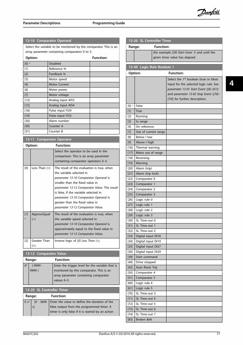
13-10 Comparator Operand
Select the variable to be monitored by the comparator. This is anarray parameter containing comparators 0 to 5.
Option: Function:
[0] * Disabled
[1] Reference %
[2] Feedback %
[3] Motor speed
[4] Motor Current
[6] Motor power
[7] Motor voltage
[12] Analog input AI53
[13] Analog input AI54
[18] Pulse input FI29
[19] Pulse input FI33
[20] Alarm number
[30] Counter A
[31] Counter B
13-11 Comparator Operator
Option: Function:
Select the operator to be used in thecomparison. This is an array parametercontaining comparator operators 0–5.
[0] Less Than (<) The result of the evaluation is true, whenthe variable selected inparameter 13-10 Comparator Operand issmaller than the fixed value in parameter 13-12 Comparator Value. The resultis false, if the variable selected inparameter 13-10 Comparator Operand isgreater than the fixed value in parameter 13-12 Comparator Value.
[1]*
Approx.Equal(~)
The result of the evaluation is true, whenthe variable speed selected inparameter 13-10 Comparator Operand isapproximately equal to the fixed value in parameter 13-12 Comparator Value.
[2] Greater Than(>)
Inverse logic of [0] Less Than (<).
13-12 Comparator Value
Range: Function:
0* [-9999 -9999 ]
Enter the trigger level for the variable that ismonitored by this comparator. This is anarray parameter containing comparatorvalues 0–5.
13-20 SL Controller Timer
Range: Function:
0 s* [0 - 3600s]
Enter the value to define the duration of thefalse output from the programmed timer. Atimer is only false if it is started by an action
13-20 SL Controller Timer
Range: Function:(for example [29] Start timer 1) and until thegiven timer value has elapsed.
13-40 Logic Rule Boolean 1
Option: Function:
Select the 1st boolean (true or false)input for the selected logic rule. See parameter 13-01 Start Event ([0]–[61])and parameter 13-02 Stop Event ([70]–[74]) for further description.
[0] * False
[1] True
[2] Running
[3] In range
[4] On reference
[7] Out of current range
[8] Below I low
[9] Above I high
[16] Thermal warning
[17] Mains out of range
[18] Reversing
[19] Warning
[20] Alarm (trip)
[21] Alarm (trip lock)
[22] Comparator 0
[23] Comparator 1
[24] Comparator 2
[25] Comparator 3
[26] Logic rule 0
[27] Logic rule 1
[28] Logic rule 2
[29] Logic rule 3
[30] SL Time-out 0
[31] SL Time-out 1
[32] SL Time-out 2
[33] Digital input DI18
[34] Digital input DI19
[35] Digital input DI27
[36] Digital input DI29
[39] Start command
[40] Drive stopped
[42] Auto Reset Trip
[50] Comparator 4
[51] Comparator 5
[60] Logic rule 4
[61] Logic rule 5
[70] SL Time-out 3
[71] SL Time-out 4
[72] SL Time-out 5
[73] SL Time-out 6
[74] SL Time-out 7
[83] Broken Belt
Parameter Descriptions Programming Guide
MG07C202 Danfoss A/S © 03/2016 All rights reserved. 77
4 4

13-41 Logic Rule Operator 1
Option: Function:
Select the 1st logical operator to use on theboolean inputs from parameter 13-40 LogicRule Boolean 1 and parameter 13-42 Logic RuleBoolean 2.
[0] * Disabled Ignores parameter 13-42 Logic Rule Boolean 2, parameter 13-43 Logic Rule Operator 2, and parameter 13-44 Logic Rule Boolean 3.
[1] AND Evaluates the expression [13-40] AND [13-42].
[2] OR Evaluates the expression [13-40] OR [13-42].
[3] AND NOT Evaluates the expression [13-40] AND NOT[13-42].
[4] OR NOT Evaluates the expression [13-40] OR NOT[13-42].
[5] NOT AND Evaluates the expression NOT [13-40] AND[13-42].
[6] NOT OR Evaluates the expression NOT [13-40] OR[13-42].
[7] NOT ANDNOT
Evaluates the expression NOT [13-40] ANDNOT [13-42].
[8] NOT ORNOT
Evaluates the expression NOT [13-40] OR NOT[13-42].
13-42 Logic Rule Boolean 2
Option: Function:
Select the 2nd boolean (true or false)input for the selected logic rule. See parameter 13-01 Start Event ([0]–[61]),and parameter 13-02 Stop Event ([70]–[74]) for further description.
[0] * False
[1] True
[2] Running
[3] In range
[4] On reference
[7] Out of current range
[8] Below I low
[9] Above I high
[16] Thermal warning
[17] Mains out of range
[18] Reversing
[19] Warning
[20] Alarm (trip)
[21] Alarm (trip lock)
[22] Comparator 0
[23] Comparator 1
[24] Comparator 2
[25] Comparator 3
[26] Logic rule 0
[27] Logic rule 1
13-42 Logic Rule Boolean 2
Option: Function:
[28] Logic rule 2
[29] Logic rule 3
[30] SL Time-out 0
[31] SL Time-out 1
[32] SL Time-out 2
[33] Digital input DI18
[34] Digital input DI19
[35] Digital input DI27
[36] Digital input DI29
[39] Start command
[40] Drive stopped
[42] Auto Reset Trip
[50] Comparator 4
[51] Comparator 5
[60] Logic rule 4
[61] Logic rule 5
[70] SL Time-out 3
[71] SL Time-out 4
[72] SL Time-out 5
[73] SL Time-out 6
[74] SL Time-out 7
[83] Broken Belt
13-43 Logic Rule Operator 2
Option: Function:
Select the 2nd logical operator to be used onthe boolean input calculated in parameter 13-40 Logic Rule Boolean 1, parameter 13-41 Logic Rule Operator 1, and parameter 13-42 Logic Rule Boolean 2, andthe boolean input coming from parameter 13-42 Logic Rule Boolean 2. Parameter 13-42 Logic Rule Boolean 2signifies the boolean input of parameter 13-44 Logic Rule Boolean 3. Parameter 13-40 Logic Rule Boolean 1, and parameter 13-42 Logic Rule Boolean 2 signifythe boolean input calculated in parameter 13-40 Logic Rule Boolean 1, parameter 13-41 Logic Rule Operator 1, and parameter 13-42 Logic Rule Boolean 2.
[0] * Disabled Ignores parameter 13-44 Logic Rule Boolean 3.
[1] AND
[2] OR
[3] AND NOT
[4] OR NOT
[5] NOT AND
[6] NOT OR
[7] NOT ANDNOT
[8] NOT OR NOT
Parameter Descriptions VLT® Midi Drive FC 280
78 Danfoss A/S © 03/2016 All rights reserved. MG07C202
44

13-44 Logic Rule Boolean 3
Option: Function:
Select the 3rd boolean (true or false)input for the selected logic rule. See parameter 13-40 Logic Rule Boolean 1, parameter 13-41 Logic Rule Operator 1,and parameter 13-42 Logic RuleBoolean 2, and the boolean input.See parameter 13-01 Start Event ([0]–[61]), and parameter 13-02 Stop Event([70]–[74]) for further description.
[0] * False
[1] True
[2] Running
[3] In range
[4] On reference
[7] Out of current range
[8] Below I low
[9] Above I high
[16] Thermal warning
[17] Mains out of range
[18] Reversing
[19] Warning
[20] Alarm (trip)
[21] Alarm (trip lock)
[22] Comparator 0
[23] Comparator 1
[24] Comparator 2
[25] Comparator 3
[26] Logic rule 0
[27] Logic rule 1
[28] Logic rule 2
[29] Logic rule 3
[30] SL Time-out 0
[31] SL Time-out 1
[32] SL Time-out 2
[33] Digital input DI18
[34] Digital input DI19
[35] Digital input DI27
[36] Digital input DI29
[39] Start command
[40] Drive stopped
[42] Auto Reset Trip
[50] Comparator 4
[51] Comparator 5
[60] Logic rule 4
[61] Logic rule 5
[70] SL Time-out 3
[71] SL Time-out 4
[72] SL Time-out 5
[73] SL Time-out 6
[74] SL Time-out 7
[83] Broken Belt
13-51 SL Controller Event
Option: Function:
Select the 3rd boolean (true or false)input for the selected logic rule. See parameter 13-40 Logic Rule Boolean 1, parameter 13-41 Logic Rule Operator 1, parameter 13-42 Logic Rule Boolean 2,and the boolean input. See parameter 13-01 Start Event ([0]–[61])and parameter 13-02 Stop Event ([70]–[74]) for further description.
[0] * False
[1] True
[2] Running
[3] In range
[4] On reference
[7] Out of current range
[8] Below I low
[9] Above I high
[16] Thermal warning
[17] Mains out of range
[18] Reversing
[19] Warning
[20] Alarm (trip)
[21] Alarm (trip lock)
[22] Comparator 0
[23] Comparator 1
[24] Comparator 2
[25] Comparator 3
[26] Logic rule 0
[27] Logic rule 1
[28] Logic rule 2
[29] Logic rule 3
[30] SL Time-out 0
[31] SL Time-out 1
[32] SL Time-out 2
[33] Digital input DI18
[34] Digital input DI19
[35] Digital input DI27
[36] Digital input DI29
[39] Start command
[40] Drive stopped
[42] Auto Reset Trip
[50] Comparator 4
[51] Comparator 5
[60] Logic rule 4
[61] Logic rule 5
[70] SL Time-out 3
[71] SL Time-out 4
[72] SL Time-out 5
[73] SL Time-out 6
[74] SL Time-out 7
[83] Broken Belt
Parameter Descriptions Programming Guide
MG07C202 Danfoss A/S © 03/2016 All rights reserved. 79
4 4

13-52 SL Controller Action
Option: Function:
[0] * Disabled Select the action corresponding to the SLCevent. Actions are executed when thecorresponding event (defined in parameter 13-51 SL Controller Event) isevaluated as true.
[1] No action
[2] Select set-up1
Changes the active set-up(parameter 0-10 Active Set-up) to 1. If the set-up is changed, it merges with other set-upcommands coming from either the digitalinputs, or via a fieldbus.
[3] Select set-up2
Changes the active set-up(parameter 0-10 Active Set-up) to 2. If the set-up is changed, it merges with other set-upcommands coming from either the digitalinputs, or via a fieldbus.
[4] Select set-up3
Changes the active set-up(parameter 0-10 Active Set-up) to 3. If the set-up is changed, it merges with other set-upcommands coming from either the digitalinputs, or via a fieldbus.
[5] Select set-up4
Changes the active set-up(parameter 0-10 Active Set-up) to 4. If the set-up is changed, it merges with other set-upcommands coming from either the digitalinputs, or via a fieldbus.
[10] Select presetref 0
Select preset reference 0. If the active presetreference is changed, it merges with otherpreset reference commands coming fromeither the digital inputs or via a fieldbus.
[11] Select presetref 1
Selects preset reference 1. If the activepreset reference is changed, it merges withother preset reference commands comingfrom either the digital inputs, or via afieldbus.
[12] Select presetref 2
Selects preset reference 2. If the activepreset reference is changed, it merges withother preset reference commands comingfrom either the digital inputs, or via afieldbus.
[13] Select presetref 3
Selects preset reference 3. If the activepreset reference is changed, it merges withother preset reference commands comingfrom either the digital inputs, or via afieldbus.
[14] Select presetref 4
Selects preset reference 4. If the activepreset reference is changed, it merges withother preset reference commands comingfrom either the digital inputs, or via afieldbus.
13-52 SL Controller Action
Option: Function:
[15] Select presetref 5
Selects preset reference 5. If the activepreset reference is changed, it merges withother preset reference commands comingfrom either the digital inputs, or via afieldbus.
[16] Select presetref 6
Selects preset reference 6. If the activepreset reference is changed, it merges withother preset reference commands comingfrom either the digital inputs, or via afieldbus.
[17] Select presetref 7
Selects preset reference 7. If the activepreset reference is changed, it merges withother preset reference commands comingfrom either the digital inputs, or via afieldbus.
[18] Select ramp1
Selects ramp 1.
[19] Select ramp2
Selects ramp 2.
[22] Run Issues a start command to the frequencyconverter.
[23] Run reverse Issues a start reverse command to thefrequency converter.
[24] Stop Issues a stop command to the frequencyconverter.
[25] Qstop Issues a quick stop command to thefrequency converter.
[26] DC Brake Issues a DC-brake command to thefrequency converter.
[27] Coast The frequency converter coasts immediately.All stop commands including the coastcommand stop the SLC.
[28] Freezeoutput
Freezes the output of the frequencyconverter.
[29] Start timer 0 See parameter 13-20 SL Controller Timer forfurther description.
[30] Start timer 1 See parameter 13-20 SL Controller Timer forfurther description.
[31] Start timer 2 See parameter 13-20 SL Controller Timer forfurther description.
[32] Set digitalout A low
Any output with SL output A is low.
[33] Set digitalout B low
Any output with SL output B is low.
[34] Set digitalout C low
Any output with SL output C is low.
[35] Set digitalout D low
Any output with SL output D is low.
[38] Set digitalout A high
Any output with SL output A is high.
Parameter Descriptions VLT® Midi Drive FC 280
80 Danfoss A/S © 03/2016 All rights reserved. MG07C202
44

13-52 SL Controller Action
Option: Function:
[39] Set digitalout B high
Any output with SL output B is high.
[40] Set digitalout C high
Any output with SL output C is high.
[41] Set digitalout D high
Any output with SL output D is high.
[60] ResetCounter A
Resets counter A to 0.
[61] ResetCounter B
Resets counter B to 0.
[70] Start Timer 3 See parameter 13-20 SL Controller Timer forfurther description.
[71] Start Timer 4 See parameter 13-20 SL Controller Timer forfurther description.
[72] Start Timer 5 See parameter 13-20 SL Controller Timer forfurther description.
[73] Start Timer 6 See parameter 13-20 SL Controller Timer forfurther description.
[74] Start Timer 7 See parameter 13-20 SL Controller Timer forfurther description.
Parameter Descriptions Programming Guide
MG07C202 Danfoss A/S © 03/2016 All rights reserved. 81
4 4

4.14 Parameters: 14-** Special Functions
14-01 Switching Frequency
Option: Function:
Select the inverter switching frequency. Changingthe switching frequency helps to reduce acousticnoise from the motor.
[2] 2.0 kHz
[3] 3.0 kHz
[4] 4.0 kHz
[5] 5.0 kHz
[6] 6.0 kHz
[7] 8.0 kHz
[8] 10.0 kHz
[9] 12.0 kHz
[10] 16.0 kHz
14-03 Overmodulation
Option: Function:
[0] Off To avoid torque ripple on the motor shaft, select [0]Off for no overmodulation of the output voltage. Thisfeature may be useful for applications such as grindingmachines.
[1] * On Select [1] On to enable the overmodulation functionfor the output voltage. Select this setting when it isrequired that the output voltage is >95% of the inputvoltage (typical when running oversynchronously). Theoutput voltage is increased according to the degree ofovermodulation.
NOTICEOvermodulation leads to increased torqueripple as harmonics are increased.
14-07 Dead Time Compensation Level
Range: Function:
Sizerelated*
[0 -100 ]
Level of applied deadtime compensationin percentage. A high level (>90%)optimizes the dynamic motor response; alevel 50–90% is good for both motor-torque-ripple minimization and themotor dynamics. A 0-level turns thedeadtime compensation off.
14-08 Damping Gain Factor
Range: Function:
Size related* [0 - 100 %] Damping factor for DC-link voltagecompensation.
14-09 Dead Time Bias Current Level
Range: Function:
Size related* [0 - 100 %] Set a bias signal (in [%]) to add tothe current-sense signal for deadtimecompensation for some motors.
14-10 Mains Failure
Option: Function:
NOTICEParameter 14-10 Mains Failure cannot bechanged while motor is running.
Parameter 14-10 Mains Failure is typically usedwhere very short mains interruptions (voltagedips) are present. At 100% load and a shortvoltage interruption, the DC voltage on the maincapacitors drops quickly. For larger frequencyconverters, it only takes a few milliseconds beforethe DC level is down to about 373 V DC and theIGBTs cut off and lose control of the motor. Whenmains is restored, and the IGBTs start again, theoutput frequency, and voltage vector do notcorrespond to the speed/frequency of the motor,and the result is normally an overvoltage orovercurrent, mostly resulting in a trip lock. Parameter 14-10 Mains Failure can be programmedto avoid this situation.
Select the function to which the frequencyconverter must act when the threshold inparameter 14-11 Mains Voltage at Mains Fault hasbeen reached.
[0]*
Nofunction
The frequency converter does not compensate fora mains interruption. The voltage on the DC-linkdrops quickly, and the motor is lost withinmilliseconds to seconds. Trip lock is the result.
[1] Ctrl.ramp-down
The frequency converter remains control of themotor and does a controlled ramp-down from parameter 14-11 Mains Voltage at Mains Fault level.If parameter 2-10 Brake Function is [0] Off or [2] ACbrake, the ramp follows the overvoltage ramping.If parameter 2-10 Brake Function is [1] ResistorBrake, the ramp follows the setting inparameter 3-81 Quick Stop Ramp Time. Thisselection is particularly useful in pumpapplications, where the inertia is low and thefriction is high. When mains is restored, theoutput frequency ramps the motor up to thereference speed (if the mains interruption isprolonged, the controlled ramp-down might takethe output frequency down to 0 RPM, and whenthe mains is restored, the application is rampedup from 0 RPM to the previous reference speedvia the normal ramp up). If the energy in the DC-link disappears before the motor is ramped to 0,the motor is coasted.
[2] Ctrl.ramp-down,trip
This selection is similar to selection [1] Ctrl. ramp-down, except that in [2] Ctrl. ramp-down, trip areset is necessary for starting up after power-up.
[3] Coasting Centrifuges can run for an hour without powersupply. In those situations, it is possible to select a
Parameter Descriptions VLT® Midi Drive FC 280
82 Danfoss A/S © 03/2016 All rights reserved. MG07C202
44

14-10 Mains Failure
Option: Function:coast function at mains interruption, together witha flying start, which occurs when the mains isrestored.
[4] Kineticback-up
Kinetic back-up ensures that the frequencyconverter keeps running as long as there is energyin the system due to the inertia from motor andload. This is done by converting the mechanicalenergy to the DC-link and thereby maintainingcontrol of the frequency converter and motor. Thiscan extend the controlled operation, dependingon the inertia in the system. For fans, it is typicallyseveral seconds, for pumps up to 2 s and forcompressors only for a fraction of a second. Manyindustry applications can extend controlledoperation for many seconds, which is oftenenough time for the mains to return.
130B
C918
.10
U
14-11*1.35
Refn [RPM]
t [S]
A B C D E ADC
UDC
[V]
t [S]
A Normal operation
B Mains failure
C Kinetic back-up
D Mains return
E Normal operation: Ramping
Illustration 4.17 Kinetic Back-up
The DC-level during [4] Kinetic back-up is parameter 14-11 Mains Voltage at Mains Fault x1.35.If the mains does not return, UDC is maintained aslong as possible by ramping the speed downtowards 0 RPM. Finally, the frequency convertercoasts.
If mains returns while in kinetic back-up, UDC
increases above parameter 14-11 Mains Voltage atMains Fault x 1.35. This is detected in 1 of thefollowing ways:
• If UDC >parameter 14-11 Mains Voltage atMains Fault x 1.35 x 1.05
• If the speed is above the reference. Thisis relevant if mains comes back at alower level than before, for example, parameter 14-11 Mains Voltage at MainsFault x 1.35 x 1.02. This does not fulfillthe criterion above, and the frequencyconverter tries to reduce UDC to parameter 14-11 Mains Voltage at Mains
14-10 Mains Failure
Option: Function:Fault x 1.35 by increasing the speed. Thisdoes not succeed as mains cannot belowered.
• If running motoric. The same mechanismas in the previous point, but where theinertia prevents that the speed goesabove the reference speed. This leads tothe motor running motoric until thespeed is above the reference speed, andthe above situation occurs. Instead ofwaiting for that, the present criterion isintroduced.
[5] Kineticback-up,trip
The difference between kinetic back-up with andwithout trip is that the latter always ramps downto 0 RPM and trips, regardless of whether mainsreturn or not.The function is made so that it does not evendetect if mains return, this is the reason for therelatively high level on the DC-link during rampdown.
14-11*1.35
Ref
790 V
0
A B C D
130B
C92
0.10U
n [RPM]
t [S]
DC
UDC
[V]
t [S]
A Normal operation
B Mains failure
C Kinetic back-up
D Trip
Illustration 4.18 Kinetic Back-up Trip
[6] Alarm
[7] Kin.back-up,trip wrecovery
14-11 Mains Voltage at Mains Fault
Range: Function:
342 V* [100 -800 V]
This parameter defines the threshold voltageat which the selected function in parameter 14-10 Mains Failure is activated.
The detection level is at a factor sqrt2 of thevalue in this parameter.
Parameter Descriptions Programming Guide
MG07C202 Danfoss A/S © 03/2016 All rights reserved. 83
4 4

14-12 Function at Mains Imbalance
Option: Function:
Operation under severe mains imbalanceconditions reduces the lifetime of the motor.Conditions are considered severe if the motor isoperated continuously near nominal load (forexample, a pump or fan running near full speed).
[0] * Trip Trips the frequency converter.
[1] Warning Issues a warning.
[2] Disabled No action is taken.
14-15 Kin. Backup Trip Recovery Level
Range: Function:
Size related* [0 - 500.000 ReferenceFeedbackUnit]
14-20 Reset Mode
Option: Function:
WARNINGUNINTENDED STARTWhen the frequency converter isconnected to AC mains, DC supply,or load sharing, the motor maystart at any time. Unintended startduring programming, service, orrepair work can result in death,serious injury, or property damage.The motor can start via an externalswitch, a fieldbus command, aninput reference signal from the LCP,or after a cleared fault condition.To prevent unintended motor start:
• Disconnect the frequencyconverter from the mains.
• Press [Off/Reset] on theLCP before programmingparameters.
• Fully wire and assemblythe frequency converter,motor, and any drivenequipment beforeconnecting the frequencyconverter to AC mains, DCsupply, or load sharing.
14-20 Reset Mode
Option: Function:
NOTICEIf the specified number ofautomatic resets is reached within10 minutes, the frequencyconverter enters [0] Manual resetmode. After the manual reset isperformed, the setting of parameter 14-20 Reset Mode revertsto the original selection. If thenumber of automatic resets is notreached within 10 minutes, orwhen a manual reset is performed,the internal automatic resetcounter returns to 0.
Select the reset function after tripping.Once reset, the frequency converter canbe restarted.
[0] * Manual reset Select [0] Manual reset, to perform areset via [Reset] or via the digital inputs.
[1] Automatic resetx 1
Select [1]-[12] Automatic reset x 1…x 20to perform between 1 and 20 automaticresets after tripping.
[2] Automatic resetx 2
[3] Automatic resetx 3
[4] Automatic resetx 4
[5] Automatic resetx 5
[6] Automatic resetx 6
[7] Automatic resetx 7
[8] Automatic resetx 8
[9] Automatic resetx 9
[10] Automatic resetx 10
[11] Automatic resetx 15
[12] Automatic resetx 20
[13] Infinite autoreset
Select [13] Infinite Automatic Reset forcontinuous resetting after tripping.
[14] Reset at power-up
Parameter Descriptions VLT® Midi Drive FC 280
84 Danfoss A/S © 03/2016 All rights reserved. MG07C202
44

14-21 Automatic Restart Time
Range: Function:
10 s* [0 - 600s]
Enter the time interval from trip to start of theautomatic reset function. This parameter isactive when parameter 14-20 Reset Mode is setto [1]–[13] Automatic reset.
14-22 Operation Mode
Option: Function:
Specify normal operation, perform tests, orinitialize all parameters except for parameter 15-03 Power Up's, parameter 15-04 Over Temp's, and parameter 15-05 Over Volt's. This function isonly active when the power is cycled to thefrequency converter.
[0]*
Normaloperation
Normal operation with motor selected.
[2] Initiali-sation
Reset all parameter values to default settings,except for parameter 15-03 Power Up's, parameter 15-04 Over Temp's, and parameter 15-05 Over Volt's. The frequencyconverter resets during the next power-up.
14-24 Trip Delay at Current Limit
Range: Function:
60 s* [0 -60 s]
Enter the current limit trip delay in seconds. Whenthe output current reaches the current limit(parameter 4-18 Current Limit), a warning istriggered. When the current limit warning hasbeen continuously present for the period specifiedin this parameter, the frequency converter trips. Torun continuously in current limit without tripping,set the parameter to 60 s=Off. Thermal monitoringof the frequency converter remains active.
14-25 Trip Delay at Torque Limit
Range: Function:
60 s* [0 -60 s]
Enter the torque limit trip delay in seconds. Whenthe output torque reaches the torque limits(parameter 4-16 Torque Limit Motor Mode and parameter 4-17 Torque Limit Generator Mode), awarning is triggered. When the torque limitwarning has been continuously present for theperiod specified in this parameter, the frequencyconverter trips. Disable the trip delay by settingthe parameter to 60 s=Off. Thermal monitoring ofthe frequency converter remains active.
14-27 Action At Inverter Fault
Option: Function:
Select how the frequency converter reacts whenan overvoltage or grounding fault occurs.
14-27 Action At Inverter Fault
Option: Function:
[0] Trip Disables the protection filters and trips at the firstfault.
[1] * Warning Runs the protection filters normally.
14-28 Production Settings
Option: Function:
[0] * No action
[1] Service reset
[3] Software Reset
14-29 Service Code
Range: Function:
0* [0 - 0x7FFFFFFF ] For internal use only.
14-30 Current Lim Ctrl, Proportional Gain
Range: Function:
100 %* [0 - 500 %] Enter the proportional gain value for thecurrent limit controller. Selection of a highvalue makes the controller react faster. Toohigh a setting leads to controllerinstability.
14-31 Current Lim Ctrl, Integration Time
Range: Function:
0.020 s* [0.002 - 2 s] Controls the current limit controlintegration time. Setting it to a lowervalue makes it react faster. A setting toolow leads to control instability.
14-32 Current Lim Ctrl, Filter Time
Range: Function:
5 ms* [1 - 100 ms] Sets a time constant for the current limitcontroller low-pass filter.
14-40 VT Level
Range: Function:
66 %*
[40 -90 %]
NOTICEThis parameter cannot be adjusted whilethe motor is running.
NOTICEThis parameter is not active whenparameter 1-10 Motor Construction is set tooptions that enable PM motor mode.
Enter the level of motor magnetization at lowspeed. Selection of a low value reduces energyloss in the motor, but also reduces loadcapability.
Parameter Descriptions Programming Guide
MG07C202 Danfoss A/S © 03/2016 All rights reserved. 85
4 4

14-41 AEO Minimum Magnetisation
Range: Function:
66 %* [40 -75 %]
Enter the minimum allowable magnetizationfor AEO. Selection of a low value reducesenergy loss in the motor, but can alsoreduce resistance to sudden load changes.
14-44 d-axis current optimization for IPM
Range: Function:
100%*
[0 -200 %]
This parameter is available only whenparameter 1-10 Motor Construction is set to [2]PM, salient IPM, non-Sat.
Normally, VVC+ PM control automaticallyoptimizes d-axis demagnetizing current based ond-axis and q-axis settings. Whenparameter 1-10 Motor Construction is set to [2]PM, salient IPM, non-Sat, use this parameter tocompensate the saturation effect at high load.Usually, decreasing this value improves theefficiency. However, 0% means no optimizationand the d-axis current is 0 (not recommended).
14-51 DC-Link Voltage Compensation
Option: Function:
[0] Off Disables DC-link compensation.
[1] * On Enables DC-link compensation.
14-52 Fan Control
This feature is only available in frequency converters 11–75 kW(14.8–100.6 hp).
Option: Function:
[5] Constant-on mode
[6] Constant-off mode
[7] On-when-Inverter-is-on-else-offMode
[8] * Variable-speed mode
14-55 Output Filter
Option: Function:
NOTICEThis parameter cannot be changedwhile the motor is running.
Select the type of output filter connected.
[0] * No Filter
[1] Sine-Wave Filter
14-61 Function at Inverter Overload
When the frequency converter issues a frequency converteroverload warning, select whether to continue and trip thefrequency converter, or derate the output current.
Option: Function:
[0] * Trip
[1] Derate
14-63 Min Switch Frequency
Option: Function:
Set the minimum switch frequency allowed bythe output filter.
[2] * 2.0 kHz
[3] 3.0 kHz
[4] 4.0 kHz
[5] 5.0 kHz
[6] 6.0 kHz
[7] 8.0 kHz
[8] 10.0 kHz
[9] 12.0 kHz
[10] 16.0 kHz
14-64 Dead Time Compensation Zero Current Level
Option: Function:
[0] * Disabled
[1] Enabled If using a long motor cable, select this option tominimize the motor torque ripple.
14-65 Speed Derate Dead Time Compensation
Range: Function:
Sizerelated*
[ 20 -1000 Hz]
Deadtime compensation level is reducedlinearly versus output frequency fromthe maximum level set in parameter 14-07 Dead Time Compen-sation Level to a minimum level set inthis parameter.
14-89 Option Detection
Selects the behavior when an option change is detected. Thisparameter returns to [0] Protect Option Config. after an optionchange.
Option: Function:
[0] * Protect Option Config. Freezes the current settings andprevents unwanted changes whenmissing or defective options aredetected.
[1] Enable OptionChange
Settings can be changed when thesystem configuration is beingmodified.
Parameter Descriptions VLT® Midi Drive FC 280
86 Danfoss A/S © 03/2016 All rights reserved. MG07C202
44

14-90 Fault Level
Use this parameter to customize fault levels. Use the 8th elementto control the fault level of alarm 13, Overcurrent.
Option: Function:
[3] * Trip Lock Alarm is set to trip-lock.
[4] Trip w.delayed reset
Alarm is configured into trip alarm, whichcan be reset after a delay time. Forexample, if alarm 13, Overcurrent isconfigured to this option, it can be reset 3minutes after the alarm.
[5] Flystart At start-up, the frequency converter tries tocatch a spinning motor. If this option isselected, parameter 1-73 Flying Start isforced to [1] Enabled.
Index Alarm Trip lock Trip w.delayed
Flystart
0 Reserved
1 Reserved
2 Reserved
3 Reserved
4 Reserved
5 Reserved
6 Reserved
7 Overcurrent D x x
Table 4.5 Table for Selection of Action whenSelected Alarm Appears (Parameter 14-90 Fault Level)
D=Default settingx=Possible selection
Parameter Descriptions Programming Guide
MG07C202 Danfoss A/S © 03/2016 All rights reserved. 87
4 4

4.15 Parameters: 15-** Drive Information
15-00 Operating hours
Range: Function:
0 h* [0 - 0x7fffffff. h] View how many hours the frequencyconverter has run. The value is saved,when the frequency converter is turnedoff.
15-01 Running Hours
Range: Function:
0 h* [0 -0x7fffffff. h]
View how many hours the frequencyconverter has run. Reset the counter in parameter 15-07 Reset Running HoursCounter. The value is saved, when thefrequency converter is turned off.
15-02 kWh Counter
Range: Function:
0 kWh* [0 -2147483647kWh]
Registers the power consumption ofthe motor as an average value over 1hour. Reset the counter in parameter 15-06 Reset kWh Counter.
15-03 Power Up's
Range: Function:
0* [0 - 2147483647 ] View the number of times the frequencyconverter has been powered up.
15-04 Over Temp's
Range: Function:
0* [0 - 65535 ] View the number of frequency convertertemperature faults.
15-05 Over Volt's
Range: Function:
0* [0 - 65535 ] View the number of frequency converterovervoltages.
15-06 Reset kWh Counter
Option: Function:
[0] * Do not reset No reset of the kWh counter is required.
[1] Reset counter Press [OK] to reset the kWh counter to 0(see parameter 15-02 kWh Counter).
15-07 Reset Running Hours Counter
Option: Function:
[0] * Do not reset
[1] Reset counter Press [OK] to reset the running hourscounter to 0 (see parameter 15-01 RunningHours).
15-30 Alarm Log: Error Code
Range: Function:
0* [0 - 255 ] View the error code and look up its meaning inchapter 6 Troubleshooting.
15-31 InternalFaultReason
Range: Function:
0* [-32767 -32767 ]
View an extra description of the error. Thisparameter is mostly used in combinationwith alarm 38, Internal Fault.
15-40 FC Type
Range: Function:
0* [0 - 0 ] View the frequency converter type. The readout isidentical to the power field of the type codedefinition, characters 1–6.
15-41 Power Section
Range: Function:
0* [0 - 20 ] View the FC type. The readout is identical to thepower field of the type code definition, characters7–10.
15-42 Voltage
Range: Function:
0* [0 - 20 ] View the FC type. The readout is identical to thepower field type of the type code definition,characters 11–12.
15-43 Software Version
Range: Function:
0* [0 - 5 ] View the combined SW version (or packageversion) consisting of power SW and control SW.
15-44 Ordered Typecode String
Range: Function:
0* [0 - 40 ] View the type code string used for reordering thefrequency converter in its original configuration.
15-45 Actual Typecode String
Range: Function:
0* [0 - 40 ] View the actual type code.
15-46 Drive Ordering No
Range: Function:
0* [0 - 0 ] View the 8-digit ordering number used forreordering the frequency converter in its originalconfiguration.
15-48 LCP Id No
Range: Function:
0* [0 - 20 ] View the LCP ID number.
Parameter Descriptions VLT® Midi Drive FC 280
88 Danfoss A/S © 03/2016 All rights reserved. MG07C202
44

15-49 SW ID Control Card
Range: Function:
0* [0 - 20 ] View the control card software version number.
15-50 SW ID Power Card
Range: Function:
0* [0 - 20 ] View the power card software version number.
15-51 Frequency Converter Serial Number
Range: Function:
0* [0 - 10 ] View the frequency converter serial number.
15-52 OEM Information
Range: Function:
0* [0 - 0]
15-53 Power Card Serial Number
Range: Function:
0* [0 - 19 ] View the power card serial number.
15-57 File Version
Range: Function:
0* [0 - 255]
15-59 Filename
Range: Function:
0* [0 - 16]
15-60 Option Mounted
Range: Function:
Size related* [0 - 30 ] View the installed option type.
15-61 Option SW Version
Range: Function:
Size related* [0 - 20 ] View the installed option softwareversion.
15-70 Option in Slot A
Range: Function:
0* [0 - 30 ] View the type code string for the option installedin slot A, and a translation of the type code string.
15-71 Slot A Option SW Version
Range: Function:
0* [0 - 20 ] View the software version for the option installedin slot A.
15-92 Defined Parameters
Range: Function:
0* [0 - 2000 ] View a list of all defined parameters in thefrequency converter. The list ends with 0.
15-97 Application Type
Range: Function:
0* [0 - 0xFFFFFFFF ] This parameter contains data used byMCT 10 Set-up Software.
15-98 Drive Identification
Range: Function:
0* [0 - 56 ] This parameter contains data used by MCT 10 Set-up Software.
15-99 Parameter Metadata
Range: Function:
0* [0 - 9999 ] This parameter contains data used by MCT 10Set-up Software.
Parameter Descriptions Programming Guide
MG07C202 Danfoss A/S © 03/2016 All rights reserved. 89
4 4

4.16 Parameters: 16-** Data Readouts
16-00 Control Word
Range: Function:
0* [0 - 65535 ] View the control word sent from the frequencyconverter via the serial communication port inhex code.
16-01 Reference [Unit]
Range: Function:
0 ReferenceFeed-backUnit*
[-4999 - 4999ReferenceFeed-backUnit]
View the present referencevalue applied on impulseor analog basis in the unitresulting from the configu-ration selected inparameter 1-00 Configu-ration Mode.
16-02 Reference [%]
Range: Function:
0 %* [-200 -200 %]
View the total reference. The total referenceis the sum of digital, analog, preset, bus,and freeze references, plus catch up andslow down.
16-03 Status Word
Range: Function:
0* [0 - 65535 ] View the status word sent from the frequencyconverter via the serial communication port inhex code.
16-05 Main Actual Value [%]
Range: Function:
0 %* [-200 - 200 %] View the 2-byte word sent with the statusword to the bus master reporting themain actual value.
16-09 Custom Readout
Range: Function:
0 CustomRea-doutUnit*
[0 - 9999CustomRea-doutUnit]
View the custom readout fromparameter 0-30 CustomReadout Unit to parameter 0-32 CustomReadout Max Value.
16-10 Power [kW]
Range: Function:
0 kW* [0 -1000kW]
Shows motor power in kW. The calculatedvalue shown is based on the actual DC-linkvoltage and DC-Link current. The value isfiltered, and therefore approximately 128 msmay pass from when an input value changes towhen the data readout values change. Theresolution of readout value on fieldbus is in 1W steps.
16-11 Power [hp]
Range: Function:
0 hp* [0 -1000 hp]
View the motor power in hp. The value shownis calculated on the basis of the actual DC-linkvoltage and DC-link current. The value isfiltered, and therefore approximately 128 msmay pass from when an input value changesto when the data readout values change.
16-12 Motor Voltage
Range: Function:
0 V* [0 - 65535 V] View the motor voltage, a calculated valueis used for controlling the motor.
16-13 Frequency
Range: Function:
0 Hz* [0 - 6553.5 Hz] View the motor frequency, withoutresonance dampening.
16-14 Motor current
Range: Function:
0 A* [0 - 655.35A]
View the motor current measured as anaverage value, IRMS. The value is filtered, andapproximately 30 ms may pass from whenan input value changes to when the datareadout values change.
16-15 Frequency [%]
Range: Function:
0 %* [0 -6553.5 %]
View a 2-byte word reporting the actualmotor frequency (without resonancedampening) as a percentage (scale0000-4000 hex) of parameter 4-19 MaxOutput Frequency.
16-16 Torque [Nm]
Range: Function:
0 Nm [-30000 -30000 Nm]
View the torque value with sign, applied tothe motor shaft. Some motors supply morethan 160% torque. As a result, the minimumvalue and the maximum value depend onthe maximum motor current as well as themotor used.
16-18 Motor Thermal
Range: Function:
0 %* [0 -100 %]
View the calculated thermal load on the motor.The cut-out limit is 100%. The basis forcalculation is the ETR function selected inparameter 1-90 Motor Thermal Protection.
Parameter Descriptions VLT® Midi Drive FC 280
90 Danfoss A/S © 03/2016 All rights reserved. MG07C202
44

16-20 Motor Angle
Range: Function:
0* [0 - 65535] View the current encoder angle offset relative tothe index position. The value range of 0–65535corresponds to 0–2xpi (radians).
16-22 Torque [%]
Range: Function:
0 %* [ -200– 200 % ] View the torque in percent of nominaltorque, with sign, applied to the motorshaft.
16-30 DC Link Voltage
Range: Function:
0 V* [0 - 65535 V] View a measured value. The value is filteredwith a 30 ms time constant.
16-33 Brake Energy Average
Range: Function:
0 kW* [0 - 10000kW]
View the brake power transmitted to anexternal brake resistor. The mean power iscalculated on an average basis for themost recent 120 s.
16-34 Heatsink Temp.
Range: Function:
0 °C* [-128 - 127 °C] View the frequency converter heat sinktemperature.
16-35 Inverter Thermal
Range: Function:
0 %* [0 - 255 %] View the percentage load on the inverter.
16-36 Inv. Nom. Current
Range: Function:
0 A* [0 - 655.35 A] View the inverter nominal current, whichshould match the nameplate data on theconnected motor. The data is used forcalculation of torque and motor protection.
16-37 Inv. Max. Current
Range: Function:
0 A* [0 - 655.35 A] View the inverter maximum current, whichshould match the nameplate data on theconnected motor. The data is used forcalculation of torque and motor protection.
16-38 SL Controller State
Range: Function:
0* [0 - 20 ] View the state of the event under execution bythe SL controller.
16-39 Control Card Temp.
Range: Function:
0 °C* [0 - 65535 °C] View the temperature on the control card,
stated in °C.
16-50 External Reference
Range: Function:
0 %* [-200 -200 %]
View the total reference, the sum ofdigital, analog, preset, bus, and freezereferences, plus catch-up and slow-down.
16-52 Feedback[Unit]
Range: Function:
0ProcessCtrlUnit*
[-4999 - 4999ProcessCtrlUnit]
View the feedback unitresulting from the selectionof unit and scaling in parameter 3-00 ReferenceRange,parameter 3-01 Reference/Feedback Unit, parameter 3-02 MinimumReference, and parameter 3-03 MaximumReference.
16-53 Digi Pot Reference
Range: Function:
0* [-200 -200 ]
View the torque value with sign, applied to themotor shaft. Some motors supply more than160% torque. As a result, the minimum valueand the maximum value depend on themaximum motor current as well as the motorused.
16-57 Feedback [RPM]
Range: Function:
0 RPM* [-30000 -30000 RPM]
Readout parameter where the actual motorRPM from the feedback source can be readin both closed loop and open loop. Thefeedback source is selected inparameter 7-00 Speed PID Feedback Source.
Parameter Descriptions Programming Guide
MG07C202 Danfoss A/S © 03/2016 All rights reserved. 91
4 4

16-60 Digital Input
Range: Function:
0* [0 -65535 ]
View the actual state of the digital inputs 18, 19,27, 29, 32, and 33.
Bit 0 Digital input terminal 33
Bit 1 Digital input terminal 32
Bit 2 Digital input terminal 29
Bit 3 Digital input terminal 27
Bit 4 Digital input terminal 19
Bit 5 Digital input terminal 18
Bit 6–15 Unused
Table 4.6 Bits Definition
16-61 Terminal 53 Setting
Shows the setting of input terminal 53.
Option: Function:
[1] Voltage mode
[6] Digital input
16-62 Analog Input 53
Range: Function:
1* [0 - 20 ] View the actual value at input 53.
16-63 Terminal 54 Setting
Option: Function:
View the setting of input terminal 54.
[0] Current mode
[1] Voltage mode
16-64 Analog Input AI54
Range: Function:
1* [0 - 20 ] View the actual value at input 54.
16-65 Analog Output 42 [mA]
Range: Function:
0 mA* [0 - 20mA]
View the actual value at output 42. Thevalue shown reflects the selections inparameter 6-90 Terminal 42 Mode andparameter 6-91 Terminal 42 Analog Output.
16-66 Digital Output
Range: Function:
0* [0 - 15 ] View the binary value of all digital outputs.
16-67 Pulse Input #29 [Hz]
Range: Function:
0* [0 - 130000 ] View the actual frequency rate on terminal 29.
16-68 Pulse Input 33 [Hz]
Range: Function:
0* [0 - 130000 ] View the actual value of the frequencyapplied at terminal 33 as an impulse input.
16-69 Pulse Output 27 [Hz]
Range: Function:
0* [0 - 40000 ] View the actual value of impulses applied toterminal 27 in digital output mode.
16-71 Relay Output
Range: Function:
0* [0 - 65535 ] View the settings of all relays.
16-72 Counter A
Range: Function:
0* [-32768 -32767 ]
View the present value of counter A. Counters areuseful as comparator operands, seeparameter 13-10 Comparator Operand.The value can be reset or changed either viadigital inputs (parameter group 5-1* Digital Inputs),or by using an SLC action (parameter 13-52 SLController Action).
16-73 Counter B
Range: Function:
0* [-32768 -32767 ]
View the present value of counter B. Counters areuseful as comparator operands(parameter 13-10 Comparator Operand).The value can be reset or changed either viadigital inputs (parameter group 5-1* Digital Inputs)or by using an SLC action (parameter 13-52 SLController Action).
16-74 Prec. Stop Counter
Range: Function:
0* [0 - 2147483647] Shows the current value of the precisestop counter.
16-80 Fieldbus CTW 1
Range: Function:
0* [0 -65535 ]
View the 2-byte control word (CTW) receivedfrom the bus master. Interpretation of the CTWdepends on the fieldbus option installed and theCTW profile selected in parameter 8-10 ControlWord Profile. For more information, see relevantfieldbus manuals.
16-82 Fieldbus REF 1
Range: Function:
0* [-32768 -32767 ]
To set the reference value, view the 2-byteword sent with the control word from thebus master. For more information, refer tothe relevant fieldbus manual.
Parameter Descriptions VLT® Midi Drive FC 280
92 Danfoss A/S © 03/2016 All rights reserved. MG07C202
44

16-84 Comm. Option STW
Range: Function:
0* [0 - 65535 ] View the extended fieldbus communicationoption status word. For more information, referto the relevant fieldbus manual.
16-85 FC Port CTW 1
Range: Function:
1084* [0 -65535 ]
View the 2-byte control word (CTW) receivedfrom the bus master. Interpretation of thecontrol word depends on the fieldbus optioninstalled and the control word profileselected in parameter 8-10 Control WordProfile.
16-86 FC Port REF 1
Range: Function:
0* [-32768 - 32767 ] View the last received reference from theFC port.
16-90 Alarm Word
Range: Function:
0* [0 - 0xFFFFFFFFUL ] View the alarm word sent via the serialcommunication port in hex code.
16-91 Alarm Word 2
Range: Function:
0* [0 - 0xFFFFFFFFUL ] View the alarm word 2 sent via theserial communication port in hex code.
16-92 Warning Word
Range: Function:
0* [0 - 0xFFFFFFFFUL ] View the warning word sent via theserial communication port in hex code.
16-93 Warning Word 2
Range: Function:
0* [0 - 0xFFFFFFFFUL ] View the warning word 2 sent via theserial communication port in hex code.
16-94 Ext. Status Word
Range: Function:
0* [0 - 0xFFFFFFFFUL ] Returns the extended status word sentvia the serial communication port inhex code.
16-95 Ext. Status Word 2
Range: Function:
0* [0 - 0xFFFFFFFFUL ] Returns the extended status word 2sent via the serial communication portin hex code.
16-97 Alarm Word 3
Range: Function:
0* [0 - 0xFFFFFFFFUL] Shows the alarm word 3 sent via theserial communication port in hex code.
Parameter Descriptions Programming Guide
MG07C202 Danfoss A/S © 03/2016 All rights reserved. 93
4 4

4.17 Parameters: 18-** Data Readouts 2
18-90 Process PID Error
Range: Function:
0 %* [-200 - 200 %] Gives the present error value used by theprocess PID controller.
18-91 Process PID Output
Range: Function:
0 %* [-200 - 200 %] Gives the present raw output value fromthe process PID controller.
18-92 Process PID Clamped Output
Range: Function:
0 %* [-200 - 200 %] Gives the present output value from theprocess PID controller after the clamplimits have been observed.
18-93 Process PID Gain Scaled Output
Range: Function:
0 %* [-200 -200 %]
Gives the present output value from theprocess PID controller after the clamplimits have been observed, and theresulting value has been gain scaled.
Parameter Descriptions VLT® Midi Drive FC 280
94 Danfoss A/S © 03/2016 All rights reserved. MG07C202
44

4.18 Parameters: 21-** Ext. Closed Loop
21-09 Extended PID Enable
Select the extended CL PID controller that is to be autotuned.
Option: Function:
[0] * Disabled
[1] Enabled Ext CL1 PID
21-11 Ext. 1 Minimum Reference
Range: Function:
0 ExtPID1Unit* [ -999999.999 -999999.999ExtPID1Unit]
This parameter sets theminimum value that can beobtained by the sumsetpoint and reference.
21-12 Ext. 1 Maximum Reference
Range: Function:
100ExtPID1Unit
[ -999999.999 -999999.999ExtPID1Unit]
This parameter sets themaximum value that canbe obtained by the sum ofthe setpoint and reference.
21-13 Ext. 1 Reference Source
This parameter defines which input on the frequency convertershould be treated as the source of the reference signal.
Option: Function:
[0] * No function
[1] Analog Input 53
[2] Analog Input 54
[7] Frequency input 29
[8] Frequency input 33
21-14 Ext. 1 Feedback Source
This parameter defines which input on the frequency convertershould be treated as the source of the feedback signal.
Option: Function:
[0] * No function
[1] Analog Input 53
[2] Analog Input 54
[3] Frequency input 29
[4] Frequency input 33
21-15 Ext. 1 Setpoint
Range: Function:
0 ExtPID1Unit* [-999999.999 -999999.999ExtPID1Unit]
This parameter is used as thereference for comparingfeedback values. The setpointcan be offset with digital,analog, or bus references.
21-17 Ext. 1 Reference [Unit]
Range: Function:
0 ExtPID1Unit* [-999999.999 -999999.999 ExtPID1Unit]
Returns the resultingreference value.
21-18 Ext. 1 Feedback [Unit]
Range: Function:
0 ExtPID1Unit* [-999999.999 -999999.999 ExtPID1Unit]
Returns the feedbackvalue.
21-19 Ext. 1 Output [%]
Range: Function:
0 %* [0 - 100 %] Returns the extended closed loop 1 PIDcontroller output value.
21-20 Ext. 1 Normal/Inverse Control
Select [0] Normal if the controller output should be reducedwhen the feedback is higher than the reference. Select [1] Inverseif the output should be increased when the feedback is higherthan the reference.
Option: Function:
[0] * Normal
[1] Inverse
21-21 Ext. 1 Proportional Gain
Range: Function:
0.01* [0 - 10 ] The proportional gain indicates the number oftimes the error between the setpoint and thefeedback signal is to be applied.
21-22 Ext. 1 Integral Time
Range: Function:
10000 s* [0.01 -10000 s]
The integrator provides an increasinggain at a constant error between thesetpoint and the feedback signal. Theintegral time is the time needed by theintegrator to reach the same gain as theproportional gain.
21-23 Ext. 1 Differentation Time
Range: Function:
0 s* [0 - 10 s] The differentiator does not react to a constanterror. It only provides a gain when the errorchanges. The quicker the error changes, thestronger the gain from the differentiator.
21-24 Ext. 1 Dif. Gain Limit
Range: Function:
5* [1 - 50 ] Set a limit for the differentiator gain (DG). The DGincreases if there are fast changes. Limit the DG toobtain a pure differentiator gain at slow changesand a constant differentiator gain where quickchanges occur.
Parameter Descriptions Programming Guide
MG07C202 Danfoss A/S © 03/2016 All rights reserved. 95
4 4

4.19 Parameters: 22-** ApplicationFunctions
4.19.1 22-02 Sleepmode CL Control Mode
22-02 Sleepmode CL Control Mode
This parameter is used to set whether feedback is detected forentering sleep mode in process closed loop.
Option: Function:
[0] * Normal Detect feedback togetherwith other parameters.
[1] Simplified Don’t detect feedback. Onlycheck sleep speed and time.
22-40 Minimum Run Time
Range: Function:
10 s* [0 - 600 s] Set the wanted minimum running time forthe motor after a start command (digitalinput or bus) before entering sleep mode.
22-41 Minimum Sleep Time
Range: Function:
10 s* [0 - 600 s] Set the minimum time for staying in sleepmode. This time overrides any wake-upconditions.
22-43 Wake-Up Speed [Hz]
Range: Function:
10* [ 0 -400.0 ]
Only to be used if parameter 1-00 ConfigurationMode is set for [0] Open loop, and an externalcontroller applies speed reference. Set thereference speed at which the sleep modeshould be deactivated.
22-44 Wake-Up Ref./FB Diff
Range: Function:
10 %*
[0 -100 %]
Only to be used if parameter 1-00 ConfigurationMode is set for [1] Closed loop, and theintegrated PI controller is used for controllingthe pressure.Set the pressure drop allowed in percentage ofsetpoint for the pressure (Pset) before cancelingthe sleep mode.
22-45 Setpoint Boost
Range: Function:
0 %*
[-100-100 %]
Only to be used if parameter 1-00 ConfigurationMode is set for [1] Closed loop, and the integratedPI controller is used. In systems with for exampleconstant pressure control, it is advantageous toincrease the system pressure before the motor isstopped. This extends the time in which the motoris stopped and helps to avoid frequent start/stop.
22-45 Setpoint Boost
Range: Function:Set the desired overpressure/temperature inpercentage of setpoint for the pressure (Pset)/temperature before entering the sleep mode.If setting for 5%, the boost pressure is Pset x 1.05.The negative values can be used for cooling towercontrol where a negative change is needed.
22-46 Maximum Boost Time
Range: Function:
60s*
[0 -600 s]
Only to be used when parameter 1-00 Configu-ration Mode is set for [1] Closed loop, and theintegrated PI controller is used for controlling thepressure.Set the maximum time for which boost mode isallowed. If the set time is exceeded, sleep mode isentered, not waiting for the set boost pressure tobe reached.
22-47 Sleep Speed [Hz]
Range: Function:
0* [ 0 - 400.0 ] Set the speed below which the frequencyconverter goes into sleep mode.
22-48 Sleep Delay Time
Range: Function:
0 s* [0 - 3600 s]
22-49 Wake-Up Delay Time
Range: Function:
0 s* [0 - 3600 s]
4.19.2 22-6* Broken-belt Detection
Use broken-belt detection in both closed-loop systems andopen-loop systems for pumps and fans. If the estimatedmotor torque (current) is below the broken-belt torque(current) value (parameter 22-61 Broken Belt Torque), thefrequency converter output frequency is above or equal to15 Hz, and the condition has been active forparameter 22-62 Broken Belt Delay, parameter 22-60 BrokenBelt Function is performed.
22-60 Broken Belt Function
Option: Function:
Select the actions to be performed if the broken-belt condition is detected.
[0] * Off
[1] Warning The frequency converter continues to run, butactivates warning 95, Broken belt. A frequencyconverter digital output or a serial communicationbus communicates a warning to other equipment.
Parameter Descriptions VLT® Midi Drive FC 280
96 Danfoss A/S © 03/2016 All rights reserved. MG07C202
44

22-60 Broken Belt Function
Option: Function:
[2] Trip The frequency converter stops running andactivates alarm 95, Broken belt. A frequencyconverter digital output or a serial communicationbus communicates an alarm to other equipment.
22-61 Broken Belt Torque
Range: Function:
10 %* [5 - 100 %] Sets the broken-belt torque as a percentageof the rated motor torque.
22-62 Broken Belt Delay
Range: Function:
10 s* [0 - 600s]
Set the time for which the broken-beltconditions must be active before carrying outthe action selected in parameter 22-60 BrokenBelt Function.
Parameter Descriptions Programming Guide
MG07C202 Danfoss A/S © 03/2016 All rights reserved. 97
4 4
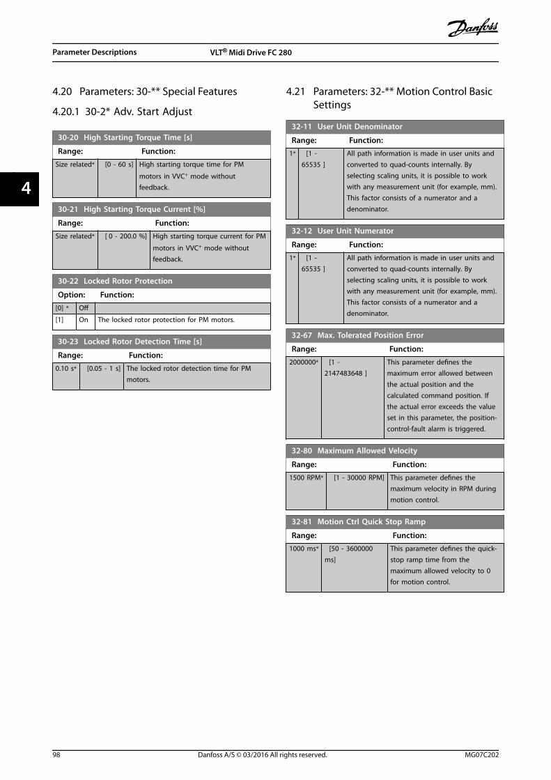
4.20 Parameters: 30-** Special Features
4.20.1 30-2* Adv. Start Adjust
30-20 High Starting Torque Time [s]
Range: Function:
Size related* [0 - 60 s] High starting torque time for PM
motors in VVC+ mode withoutfeedback.
30-21 High Starting Torque Current [%]
Range: Function:
Size related* [ 0 - 200.0 %] High starting torque current for PM
motors in VVC+ mode withoutfeedback.
30-22 Locked Rotor Protection
Option: Function:
[0] * Off
[1] On The locked rotor protection for PM motors.
30-23 Locked Rotor Detection Time [s]
Range: Function:
0.10 s* [0.05 - 1 s] The locked rotor detection time for PMmotors.
4.21 Parameters: 32-** Motion Control BasicSettings
32-11 User Unit Denominator
Range: Function:
1* [1 -65535 ]
All path information is made in user units andconverted to quad-counts internally. Byselecting scaling units, it is possible to workwith any measurement unit (for example, mm).This factor consists of a numerator and adenominator.
32-12 User Unit Numerator
Range: Function:
1* [1 -65535 ]
All path information is made in user units andconverted to quad-counts internally. Byselecting scaling units, it is possible to workwith any measurement unit (for example, mm).This factor consists of a numerator and adenominator.
32-67 Max. Tolerated Position Error
Range: Function:
2000000* [1 -2147483648 ]
This parameter defines themaximum error allowed betweenthe actual position and thecalculated command position. Ifthe actual error exceeds the valueset in this parameter, the position-control-fault alarm is triggered.
32-80 Maximum Allowed Velocity
Range: Function:
1500 RPM* [1 - 30000 RPM] This parameter defines themaximum velocity in RPM duringmotion control.
32-81 Motion Ctrl Quick Stop Ramp
Range: Function:
1000 ms* [50 - 3600000ms]
This parameter defines the quick-stop ramp time from themaximum allowed velocity to 0for motion control.
Parameter Descriptions VLT® Midi Drive FC 280
98 Danfoss A/S © 03/2016 All rights reserved. MG07C202
44

4.22 Parameters: 33-** Motion Control Adv.Settings
33-00 Homing Mode
Select the homing mode.
Option: Function:
[0] * Not forced
[1] Forced manual homing
[2] Forced automated homing
33-01 Home Offset
Range: Function:
0* [-1073741824 -1073741824 ]
Use this parameter to set an offset of0 (home position) compared to theposition after homing.
33-02 Home Ramp Time
Range: Function:
10 ms* [1 - 1000ms]
This parameter defines the ramp time (inms) from standstill to the value set in parameter 32-80 Maximum Allowed Velocity.
33-03 Homing Velocity
Range: Function:
100RPM*
[-1500 -1500 RPM]
This parameter defines the velocity ofhoming. It must not exceed the parameter 32-80 Maximum AllowedVelocity.
33-04 Homing Behaviour
Option: Function:
Define the behavior when the homeswitch is found: Reversing without index(0 pulse) search, or forwarding withoutindex search.
[1] * Reverse no index
[3] Forward no index
33-41 Negative Software Limit
Range: Function:
-500000* [-1073741824- 1073741824 ]
It is only active if during positioningand parameter 33-43 Negative SoftwareLimit Active is set to [1] Active. If it isactive and parameter 34-50 ActualPosition goes below the valuespecified in this parameter, a positioncontrol fault alarm is reported with thefault reason [5] Neg. SW Limit which isspecified in parameter 37-18 Pos. CtrlFault Reason. The maximum value isthe value specified inparameter 33-42 Positive Software Limit.The default value is the smaller valuebetween -500,000 andparameter 33-42 Positive Software Limit.
33-42 Positive Software Limit
Range: Function:
500000* [-1073741824- 1073741824 ]
It is only active during positioning andthe parameter 33-44 Positive SoftwareLimit Active is set to [1] Active. If it isactive and parameter 34-50 ActualPosition goes below the value specifiedin this parameter, a position controlfault alarm is reported with the faultreason [4] Pos. SW Limit which isspecified in parameter 37-18 Pos. CtrlFault Reason.
33-43 Negative Software Limit Active
Option: Function:
[0] * Inactive
[1] Active When this parameter is set to active, thefrequency converter continuously checks whetherthe target position is below the negative softwarelimit. If it occurs, an error is issued and thefrequency converter control is switched off.
33-44 Positive Software Limit Active
Option: Function:
[0] * Inactive
[1] Active When this parameter is set to active, thefrequency converter continuously checks whetherthe target position is above the positive softwarelimit. If it occurs, an error is issued and thefrequency converter control is switched off.
33-47 Target Position Window
Range: Function:
0* [0 - 10000 ] Defines the size of the target window with userunit. A position is only viewed as reachedwhen the actual position is within this window.
Parameter Descriptions Programming Guide
MG07C202 Danfoss A/S © 03/2016 All rights reserved. 99
4 4

4.23 Parameters: 34-** Motion Control DataReadouts
34-01 PCD 1 Write For Application
Range: Function:
0* [0 - 65535 ] Value received in PCD1 of fieldbus telegram.
34-02 PCD 2 Write For Application
Range: Function:
0* [0 - 65535 ] Value received in PCD2 of fieldbus telegram.
34-03 PCD 3 Write For Application
Range: Function:
0* [0 - 65535 ] Value received in PCD3 of fieldbus telegram.
34-04 PCD 4 Write For Application
Range: Function:
0* [0 - 65535 ] Value received in PCD4 of fieldbus telegram.
34-05 PCD 5 Write For Application
Range: Function:
0* [0 - 65535 ] Value received in PCD5 of fieldbus telegram.
34-06 PCD 6 Write For Application
Range: Function:
0* [0 - 65535 ] Value received in PCD6 of fieldbus telegram.
34-07 PCD 7 Write For Application
Range: Function:
0* [0 - 65535 ] Value received in PCD7 of fieldbus telegram.
34-08 PCD 8 Write For Application
Range: Function:
0* [0 - 65535 ] Value received in PCD8 of fieldbus telegram.
34-09 PCD 9 Write For Application
Range: Function:
0* [0 - 65535 ] Value received in PCD9 of fieldbus telegram.
34-10 PCD 10 Write For Application
Range: Function:
0* [0 - 65535 ] Value received in PCD10 of fieldbus telegram.
34-21 PCD 1 Read For Application
Range: Function:
0* [0 - 65535 ] Value sent in PCD1 of fieldbus telegram.
34-22 PCD 2 Read For Application
Range: Function:
0* [0 - 65535 ] Value sent in PCD2 of fieldbus telegram.
34-23 PCD 3 Read For Application
Range: Function:
0* [0 - 65535 ] Value sent in PCD3 of fieldbus telegram.
34-24 PCD 4 Read For Application
Range: Function:
0* [0 - 65535 ] Value sent in PCD4 of fieldbus telegram.
34-25 PCD 5 Read For Application
Range: Function:
0* [0 - 65535 ] Value sent in PCD5 of fieldbus telegram.
34-26 PCD 6 Read For Application
Range: Function:
0* [0 - 65535 ] Value sent in PCD6 of fieldbus telegram.
34-27 PCD 7 Read For Application
Range: Function:
0* [0 - 65535 ] Value sent in PCD7 of fieldbus telegram.
34-28 PCD 8 Read For Application
Range: Function:
0* [0 - 65535 ] Value sent in PCD8 of fieldbus telegram.
34-29 PCD 9 Read For Application
Range: Function:
0* [0 - 65535 ] Value sent in PCD9 of fieldbus telegram.
34-30 PCD 10 Read For Application
Range: Function:
0* [0 - 65535 ] Value sent in PCD10 of fieldbus telegram.
34-50 Actual Position
Range: Function:
0* [-1073741824 -1073741824 ]
The actual position in userunit.
34-56 Track Error
Range: Function:
0* [-2147483647 -2147483647 ]
Readout of the error betweencalculated command position andactual position in user unit.
Parameter Descriptions VLT® Midi Drive FC 280
100 Danfoss A/S © 03/2016 All rights reserved. MG07C202
44

4.24 Parameters: 37-** Application Settings
37-00 Application Mode
Option: Function:
[0] * Drive mode
[2] Position Control
37-01 Pos. Feedback Source
Option: Function:
[0] * 24V Encoder Select the position feedback source.
37-02 Pos. Target
Range: Function:
0* [-1073741824- 1073741824 ]
If parameter 37-03 Pos. Type is set to [0]Absolute, the target position is an absoluteposition (relative to home position). If the parameter 37-03 Pos. Type is set to [1] Relativeand the last position was obtained throughjogging, the target position is relative to thatposition. If the last position was reached as aresult of a positioning command, then thetarget position is relative to the last targetposition no matter whether it was reachedor not.
37-03 Pos. Type
This parameter defines the target position type.
Option: Function:
[0] * Absolute
[1] Relative
37-04 Pos. Velocity
Range: Function:
100RPM*
[1 - 30000RPM]
Defines the velocity during positioning.The maximum value must not exceed thevalue specified in parameter 32-80 Maximum Allowed Velocity.
37-05 Pos. Ramp Up Time
Range: Function:
5000ms*
[50 -100000 ms]
Defines the time in milliseconds that ittakes to ramp from standstill to parameter 32-80 Maximum AllowedVelocity.
37-06 Pos. Ramp Down Time
Range: Function:
5000ms*
[50 -100000 ms]
It is defined as the time in millisecondsthat it takes to ramp from parameter 32-80 Maximum AllowedVelocity to standstill.
37-07 Pos. Auto Brake Ctrl
When the automatic brake control function is disabled, thefrequency converter controls the application also at standstill.When the automatic brake control function is enabled, themechanical brake is automatically activated every time theapplication is at standstill for a time period specified in parameter 37-08 Pos. Hold Delay.
Option: Function:
[0] Disable
[1] * Enable
37-08 Pos. Hold Delay
Range: Function:
0 ms* [0 - 10000ms]
To be used with the automatic brakecontrol function. The hold delay is awaiting period in which the brake is notactivated even though the application is atstandstill.
37-09 Pos. Coast Delay
Range: Function:
200 ms* [0 - 1000ms]
To be used with the automatic brakecontrol function. The coast delay is thedelay from activating the mechanicalbrake to disabling the controller andcoasting the frequency converter.
37-10 Pos. Brake Delay
Range: Function:
200 ms* [0 - 1000ms]
To be used with the automatic brakecontrol function. The brake delay is thedelay after activating the control andmagnetizing the motor before openingthe brake.
37-11 Pos. Brake Wear Limit
Range: Function:
0* [0 -1073741824 ]
Set this parameter to a positive value.While the brake is activated, if thefrequency converter moves more than thelimit in user unit set in this parameter, thefrequency converter reports an alarmPOSITION CTRL FAULT with fault reasonBrake Wear Limit Exceeded.
37-12 Pos. PID Anti Windup
Configure whether to enable the anti-windup of positioning PID.
Option: Function:
[0] Disable
[1] * Enable
Parameter Descriptions Programming Guide
MG07C202 Danfoss A/S © 03/2016 All rights reserved. 101
4 4

37-13 Pos. PID Output Clamp
Range: Function:
1000* [1 -10000 ]
This parameter clamps the total output ofthe PID. A setting of 1000 corresponds to100% of parameter 32-80 Maximum AllowedVelocity.
37-14 Pos. Ctrl. Source
Selects the control source for positioning control.
Option: Function:
[0] * DI
[1] FieldBus
37-15 Pos. Direction Block
Use this parameter to configure whether to block a direction,and the direction to be blocked.
Option: Function:
[0] * No Blocking
[1] Block Reverse
[2] Block Forward
37-17 Pos. Ctrl Fault Behaviour
This parameter determines the behavior of the frequencyconverter after a fault is detected.
Option: Function:
[0] * Ramp Down&Brake
[1] Brake Directly
37-18 Pos. Ctrl Fault Reason
READ-ONLY PARAMETER: The current fault reason of the alarm.POSITION CTRL FAULT is shown in this parameter.
Option: Function:
[0] * No Fault
[1] Homing Needed
[2] Pos. HW Limit
[3] Neg. HW Limit
[4] Pos. SW Limit
[5] Neg. SW Limit
[7] Brake Wear Limit
[8] Quick Stop
[9] PID Error Too Big
[12] Rev. Operation
[13] Fwd. Operation
[20] Can not find home position
37-19 Pos. New Index
Range: Function:
0* [0 - 255 ] The currently latched index number.
Parameter Descriptions VLT® Midi Drive FC 280
102 Danfoss A/S © 03/2016 All rights reserved. MG07C202
44

5 Parameter Lists
5.1 Introduction
5.1.1 Default Settings
Changes during operationTrue means that the parameter can be changed while thefrequency converter is in operation, and false means thatthe frequency converter must be stopped before a changecan be made.
4-set-upAll set-ups: The parameter can be set individually in eachof the 4 set-ups, that is 1 single parameter can have 4different data values.1 set-up: Data value is the same in all set-ups.
Datatype
Description Type
2 Integer 8 Int8
3 Integer 16 Int16
4 Integer 32 Int32
5 Unsigned 8 Uint8
6 Unsigned 16 Uint16
7 Unsigned 32 Uint32
9 Visible String VisStr
33 Normalized value 2 bytes N2
35 Bit sequence of 16 boolean variables V2
54 Time difference w/o date TimD
Table 5.1 Data Type
5.1.2 Conversion
The various attributes of each parameter are shown inFactory Setting. Parameter values are transferred as wholenumbers only. Conversion factors are therefore used totransfer decimals.
Parameter 4-12 Motor Speed Low Limit [Hz] has a conversionfactor of 0.1. To set the minimum frequency to 10 Hz,transfer the value 100. A conversion factor of 0.1 meansthat the value transferred is multiplied by 0.1. The value100 is therefore read as 10.0.
Examples:0 s⇒conversion index 00.00 s⇒conversion index -20 ms⇒conversion index -30.00 ms⇒conversion index -5
Conversion index Conversion factor
100
75
74
67
6 1000000
5 100000
4 10000
3 1000
2 100
1 10
0 1
-1 0.1
-2 0.01
-3 0.001
-4 0.0001
-5 0.00001
-6 0.000001
-7 0.0000001
Table 5.2 Conversion Table
Parameter Lists Programming Guide
MG07C202 Danfoss A/S © 03/2016 All rights reserved. 103
5 5

5.1.3 Active/Inactive Parameters in Different Drive Control Modes
+ indicates that the parameter is active in the mode.- indicates that the parameter is inactive in the mode.
Parameter 1-10 Motor Construction AC motor
Parameter 1-01 Motor Control Principle U/f mode VVC+
Parameter 1-00 Configuration Mode
[0] Speed Open Loop + +
[1] Speed Closed Loop - +
[2] Torque Closed Loop - +
[3] Process + +
[4] Torque Open Loop - +
[7] Ext. PID Open Loop + +
Parameter 1-03 Torque Characteristics - +1, 2, 3)
Parameter 1-06 Clockwise Direction + +
Parameter 1-20 Motor Power [kW](parameter 0-03 Regional Settings = [0] International)
+ +
Parameter 1-22 Motor Voltage + +
Parameter 1-23 Motor Frequency + +
Parameter 1-24 Motor Current + +
Parameter 1-25 Motor Nominal Speed + +
Parameter 1-29 Automatic Motor Adaptation (AMA) + +
Parameter 1-30 Stator Resistance (Rs) + +
Parameter 1-33 Stator Leakage Reactance (X1) + +
Parameter 1-35 Main Reactance (Xh) + +
Parameter 1-39 Motor Poles + +
Table 5.3 Active/Inactive Parameters
1) Constant torque2) Variable torque3) AEO
Parameter 1-10 Motor Construction AC motor
Parameter 1-01 Motor Control Principle U/f mode VVC+
Parameter 1-50 Motor Magnetisation at Zero Speed - +
Parameter 1-52 Min Speed Normal Magnetising [Hz] - +
Parameter 1-55 U/f Characteristic - U + -
Parameter 1-56 U/f Characteristic - F + -
Parameter 1-60 Low Speed Load Compensation - +
Parameter 1-61 High Speed Load Compensation - +
Parameter 1-62 Slip Compensation - +4)
Parameter 1-63 Slip Compensation Time Constant +5) +
Parameter 1-64 Resonance Damping + +
Parameter 1-65 Resonance Damping Time Constant + +
Parameter 1-71 Start Delay + +
Parameter 1-72 Start Function + +
Parameter 1-73 Flying Start - +
Parameter 1-75 Start Speed [Hz] - +
Parameter 1-76 Start Current - +
Table 5.4 Active/Inactive Parameters
4) Not used when parameter 1-03 Torque Characteristics = VT.5) Part of resonance damping.
Parameter Lists VLT® Midi Drive FC 280
104 Danfoss A/S © 03/2016 All rights reserved. MG07C202
55

Parameter 1-10 Motor Construction AC motor
Parameter 1-01 Motor Control Principle U/f mode VVC+
Parameter 1-80 Function at Stop + +
Parameter 1-82 Min Speed for Function at Stop [Hz] + +
Parameter 1-90 Motor Thermal Protection + +
Parameter 1-93 Thermistor Resource + +
Parameter 2-00 DC Hold Current + +
Parameter 2-01 DC Brake Current + +
Parameter 2-02 DC Braking Time + +
Parameter 2-04 DC Brake Cut In Speed [Hz] + +
Parameter 2-10 Brake Function +6) +
Parameter 2-11 Brake Resistor (ohm) + +
Parameter 2-12 Brake Power Limit (kW) + +
Parameter 2-16 AC brake Max. Current - +
Parameter 2-17 Over-voltage Control + +
Parameter 2-19 Over-voltage Gain + +
Parameter 2-20 Release Brake Current + +
Parameter 2-22 Activate Brake Speed [Hz] + +
Table 5.5 Active/Inactive Parameters
6) Not AC brake
Parameter Lists Programming Guide
MG07C202 Danfoss A/S © 03/2016 All rights reserved. 105
5 5

5.2 Parameter Lists
5.2.1 0-** Operation and Display
Parameter # Parameter description Default value 4 set-up Change duringoperation
Conversionindex
Type
0-0* Basic Settings
0-01 Language [0] English 1 set-up TRUE - Uint8
0-03 Regional Settings [0] International 1 set-up FALSE - Uint8
0-04 Operating State at Power-up [0] Resume All set-ups TRUE - Uint8
0-06 GridType Size Related 1 set-up FALSE - Uint8
0-07 Auto DC Braking [1] On 1 set-up FALSE - Uint8
0-1* Set-up Operations
0-10 Active Set-up [1] Set-up 1 1 set-up TRUE - Uint8
0-11 Programming Set-up [9] Active Set-up 1 set-up TRUE - Uint8
0-12 Link Setups [20] Linked All set-ups FALSE - Uint8
0-14 Readout: Edit Set-ups / Channel 0 N/A All set-ups TRUE 0 Int32
0-16 Application Selection [0] None 1 set-up FALSE - Uint8
0-2* LCP Display
0-20 Display Line 1.1 Small 1602 All set-ups TRUE - Uint16
0-21 Display Line 1.2 Small 1614 All set-ups TRUE - Uint16
0-22 Display Line 1.3 Small 1610 All set-ups TRUE - Uint16
0-23 Display Line 2 Large 1613 All set-ups TRUE - Uint16
0-24 Display Line 3 Large 1502 All set-ups TRUE - Uint16
0-3* LCP Custom Readout
0-30 Custom Readout Unit [1] % 1 set-up TRUE - Uint8
0-31 Custom Readout Min Value0 CustomRea-
doutUnit 1 set-up TRUE -2 Int32
0-32 Custom Readout Max Value100 CustomRea-
doutUnit 1 set-up TRUE -2 Int32
0-37 Display Text 1 [] 1 set-up TRUE 0 VisStr[21]
0-38 Display Text 2 [] 1 set-up TRUE 0 VisStr[26]
0-39 Display Text 3 [] 1 set-up TRUE 0 VisStr[26]
0-4* LCP Keypad
0-40 [Hand on] Key on LCP [1] Enabled All set-ups TRUE - Uint8
0-42 [Auto on] Key on LCP [1] Enabled All set-ups TRUE - Uint8
0-44 [Off/Reset] Key on LCP [1] Enabled All set-ups TRUE - Uint8
0-5* Copy/Save
0-50 LCP Copy [0] No copy 1 set-up FALSE - Uint8
0-51 Set-up Copy [0] No copy 1 set-up FALSE - Uint8
0-6* Password
0-60 Main Menu Password 0 N/A 1 set-up TRUE 0 Uint16
5.2.2 1-** Load and Motor
Parameter # Parameter description Default value 4 set-up Change duringoperation
Conversionindex
Type
1-0* General Settings
1-00 Configuration Mode [0] Open Loop All set-ups TRUE - Uint8
1-01 Motor Control Principle [1] VVC+ All set-ups FALSE - Uint8
1-03 Torque Characteristics [0] Constant torque All set-ups FALSE - Uint8
1-06 Clockwise Direction [0] Normal 1 set-up FALSE - Uint8
1-08 Motor Control Bandwidth Size Related 1 set-up FALSE - Uint8
1-1* Motor Selection
Parameter Lists VLT® Midi Drive FC 280
106 Danfoss A/S © 03/2016 All rights reserved. MG07C202
55

1-10 Motor Construction [0] Asynchron 1 set-up FALSE - Uint8
1-14 Damping Gain 120 % All set-ups TRUE 0 Int16
1-15 Low Speed Filter Time Const. Size Related All set-ups TRUE -2 Uint16
1-16 High Speed Filter Time Const. Size Related All set-ups TRUE -2 Uint16
1-17 Voltage filter time const. Size Related All set-ups TRUE -3 Uint16
1-2* Motor Data
1-20 Motor Power Size Related All set-ups FALSE - Uint8
1-22 Motor Voltage Size Related All set-ups FALSE 0 Uint16
1-23 Motor Frequency Size Related All set-ups FALSE 0 Uint16
1-24 Motor Current Size Related All set-ups FALSE -2 Uint32
1-25 Motor Nominal Speed Size Related All set-ups FALSE 67 Uint16
1-26 Motor Cont. Rated Torque Size Related All set-ups FALSE -1 Uint32
1-29 Automatic Motor Adaption (AMA) [0] Off All set-ups FALSE - Uint8
1-3* Adv. Motor Data I
1-30 Stator Resistance (Rs) Size Related All set-ups FALSE -3 Uint32
1-31 Rotor Resistance (Rr) Size Related All set-ups FALSE -3 Uint32
1-33 Stator Leakage Reactance (X1) Size Related All set-ups FALSE -3 Uint32
1-35 Main Reactance (Xh) Size Related All set-ups FALSE -2 Uint32
1-37 d-axis Inductance (Ld) Size Related All set-ups FALSE -6 Int32
1-38 q-axis Inductance (Lq) Size Related All set-ups FALSE -6 Int32
1-39 Motor Poles Size Related All set-ups FALSE 0 Uint8
1-4* Adv. Motor Data II
1-40 Back EMF at 1000 RPM Size Related All set-ups FALSE 0 Uint16
1-42 Motor Cable Length 50 m All set-ups FALSE 0 Uint8
1-43 Motor Cable Length Feet 164 ft All set-ups FALSE 0 Uint16
1-44 d-axis Inductance Sat. (LdSat) Size Related All set-ups FALSE -6 Int32
1-45 q-axis Inductance Sat. (LqSat) Size Related All set-ups FALSE -6 Int32
1-46 Position Detection Gain 100 % All set-ups TRUE 0 Uint16
1-48Current at Min Inductance for d-axis 100 % All set-ups FALSE 0 Int16
1-49Current at Min Inductance for q-axis 100 % All set-ups FALSE 0 Uint16
1-5* Load Indep. Setting
1-50Motor Magnetisation at ZeroSpeed 100 % All set-ups TRUE 0 Uint16
1-52Min Speed Normal Magnetising[Hz] 1 Hz All set-ups TRUE -1 Uint16
1-55 U/f Characteristic - U Size Related All set-ups FALSE -1 Uint16
1-56 U/f Characteristic - F Size Related All set-ups FALSE -1 Uint16
1-6* Load Depen. Setting
1-60 Low Speed Load Compensation 100 % All set-ups TRUE 0 Int16
1-61 High Speed Load Compensation 100 % All set-ups TRUE 0 Int16
1-62 Slip Compensation Size Related All set-ups TRUE 0 Int16
1-63 Slip Compensation Time Constant 0.1 s All set-ups TRUE -2 Uint16
1-64 Resonance Dampening 100 % All set-ups TRUE 0 Uint16
1-65Resonance Dampening TimeConstant 0.005 s All set-ups TRUE -3 Uint16
1-66 Min. Current at Low Speed 50 % All set-ups TRUE 0 Uint32
1-7* Start Adjustments
1-70 PM Start Mode [0] Rotor Detection All set-ups TRUE - Uint8
1-71 Start Delay 0 s All set-ups TRUE -1 Uint8
1-72 Start Function[2] Coast/delay
time All set-ups TRUE - Uint8
1-73 Flying Start [0] Disabled All set-ups TRUE - Uint8
Parameter Lists Programming Guide
MG07C202 Danfoss A/S © 03/2016 All rights reserved. 107
5 5

1-75 Start Speed [Hz] Size Related All set-ups TRUE -1 Uint16
1-76 Start Current Size Related All set-ups TRUE -2 Uint32
1-78 Compressor Start Max Speed [Hz] 0 Hz All set-ups TRUE -1 Uint16
1-79Compressor Start Max Time toTrip 5 s All set-ups TRUE -1 Uint8
1-8* Stop Adjustments
1-80 Function at Stop [0] Coast All set-ups TRUE - Uint8
1-82Min Speed for Function at Stop[Hz] 0 Hz All set-ups TRUE -1 Uint16
1-83 Precise Stop Function[0] Precise ramp
stop All set-ups FALSE - Uint8
1-84 Precise Stop Counter Value 100000 N/A All set-ups TRUE 0 Uint32
1-85Precise Stop Speed CompensationDelay 10 ms All set-ups TRUE -3 Uint8
1-88 AC Brake Gain 1.4 N/A All set-ups TRUE -1 Uint16
1-9* Motor Temperature
1-90 Motor Thermal Protection [0] No protection All set-ups TRUE - Uint8
1-93 Thermistor Source [0] None All set-ups FALSE - Uint8
5.2.3 2-** Brakes
Parameter # Parameter description Default value 4 set-up Change duringoperation
Conversionindex
Type
2-0* DC-Brake
2-00 DC Hold/Motor Preheat Current 50 % All set-ups TRUE 0 Uint16
2-01 DC Brake Current 50 % All set-ups TRUE 0 Uint16
2-02 DC Braking Time 10 s All set-ups TRUE -1 Uint16
2-04 DC Brake Cut In Speed 0 Hz All set-ups TRUE -1 Uint16
2-06 Parking Current 100 % All set-ups TRUE 0 Uint16
2-07 Parking Time 3 s All set-ups TRUE -1 Uint16
2-1* Brake Energy Funct.
2-10 Brake Function [0] Off All set-ups TRUE - Uint8
2-11 Brake Resistor (ohm) Size Related All set-ups FALSE -1 Uint16
2-12 Brake Power Limit (kW) Size Related All set-ups TRUE 0 Uint32
2-14 Brake voltage reduce 0 V All set-ups FALSE 0 uint16
2-16 AC Brake, Max current 100 % All set-ups TRUE -1 Uint16
2-17 Over-voltage Control [0] Disabled All set-ups TRUE - Uint8
2-19 Over-voltage Gain 100 % All set-ups TRUE 0 Uint16
2-2* Mechanical Brake
2-20 Release Brake Current 0 A All set-ups TRUE -2 Uint32
2-22 Activate Brake Speed [Hz] 0 Hz All set-ups TRUE -1 Uint16
2-23 Activate Brake Delay 0 s All set-ups TRUE -1 Uint8
Parameter Lists VLT® Midi Drive FC 280
108 Danfoss A/S © 03/2016 All rights reserved. MG07C202
55

5.2.4 3-** Reference/Ramps
Parameter # Parameter description Default value 4 set-up Change duringoperation
Conversionindex
Type
3-0* Reference Limits
3-00 Reference Range [0] Min - Max All set-ups TRUE - Uint8
3-01 Reference/Feedback Unit Size Related All set-ups TRUE - Uint8
3-02 Minimum Reference0 ReferenceFeed-
backUnit All set-ups TRUE -3 Int32
3-03 Maximum Reference Size Related All set-ups TRUE -3 Int32
3-04 Reference Function [0] Sum All set-ups TRUE - Uint8
3-1* References
3-10 Preset Reference 0 % All set-ups TRUE -2 Int16
3-11 Jog Speed [Hz] 5 Hz All set-ups TRUE -1 Uint16
3-12 Catch up/slow Down Value 0 % All set-ups TRUE -2 Int16
3-14 Preset Relative Reference 0 % All set-ups TRUE -2 Int16
3-15 Reference 1 Source [1] Analog Input 53 All set-ups TRUE - Uint8
3-16 Reference 2 Source [0] No function All set-ups TRUE - Uint8
3-17 Reference 3 Source[11] Local bus
reference All set-ups TRUE - Uint8
3-18Relative Scaling ReferenceResource [0] No function All set-ups TRUE - Uint8
3-4* Ramp 1
3-40 Ramp 1 Type [0] Linear All set-ups TRUE - Uint8
3-41 Ramp 1 Ramp Up Time Size Related All set-ups TRUE -2 Uint32
3-42 Ramp 1 Ramp Down Time Size Related All set-ups TRUE -2 Uint32
3-5* Ramp 2
3-50 Ramp 2 Type [0] Linear All set-ups TRUE - Uint8
3-51 Ramp 2 Ramp Up Time Size Related All set-ups TRUE -2 Uint32
3-52 Ramp 2 Ramp Down Time Size Related All set-ups TRUE -2 Uint32
3-6* Ramp 3
3-60 Ramp 3 Type [0] Linear All set-ups TRUE - Uint8
3-61 Ramp 3 Ramp up Time Size Related All set-ups TRUE -2 Uint32
3-62 Ramp 3 Ramp down Time Size Related All set-ups TRUE -2 Uint32
3-7* Ramp 4
3-70 Ramp 4 Type [0] Linear All set-ups TRUE - Uint8
3-71 Ramp 4 Ramp up Time Size Related All set-ups TRUE -2 Uint32
3-72 Ramp 4 Ramp Down Time Size Related All set-ups TRUE -2 Uint32
3-8* Other Ramps
3-80 Jog Ramp Time Size Related All set-ups TRUE -2 Uint32
3-81 Quick Stop Ramp Time Size Related 1 set-up TRUE -2 Uint32
3-9* Digital Pot.Meter
3-90 Step Size 0.10 % All set-ups TRUE -2 Uint16
3-92 Power Restore [0] Off All set-ups TRUE - Uint8
3-93 Maximum Limit 100 % All set-ups TRUE 0 Int16
3-94 Minimum Limit -100 % All set-ups TRUE 0 Int16
3-95 Ramp Delay 1000 ms All set-ups TRUE -3 uint32
3-96 Maximum Limit Switch Reference 25 % All set-ups TRUE 0 Int16
Parameter Lists Programming Guide
MG07C202 Danfoss A/S © 03/2016 All rights reserved. 109
5 5

5.2.5 4-** Limits/Warnings
Parameter # Parameter description Default value 4 set-up Change duringoperation
Conversionindex
Type
4-1* Motor Limits
4-10 Motor Speed Direction [0] Clockwise All set-ups FALSE - Uint8
4-12 Motor Speed Low Limit [Hz] 0 Hz All set-ups FALSE -1 Uint16
4-14 Motor Speed High Limit [Hz] 65 Hz All set-ups FALSE -1 Uint16
4-16 Torque Limit Motor Mode Size Related All set-ups TRUE 0 Uint16
4-17 Torque Limit Generator Mode 100 % All set-ups TRUE 0 Uint16
4-18 Current Limit Size Related All set-ups TRUE 0 Uint16
4-19 Max Output Frequency Size Related All set-ups FALSE -1 Uint16
4-2* Limit Factors
4-20 Torque Limit Factor Source [0] No function All set-ups TRUE - Uint8
4-21 Speed Limit Factor Source [0] No function All set-ups TRUE - Uint8
4-22 Break Away Boost [0] Off All set-ups FALSE - Uint8
4-3* Motor Fb Monitor
4-30 Motor Feedback Loss Function [2] Trip All set-ups TRUE - Uint8
4-31 Motor Feedback Speed Error 20 Hz All set-ups TRUE 0 Uint16
4-32 Motor Feedback Loss Timeout 0.05 s All set-ups TRUE -2 Uint16
4-4* Adj. Warnings 2
4-40 Warning Freq. Low Size Related All set-ups TRUE -1 uint16
4-41 Warning Freq. High Size Related All set-ups TRUE -1 uint16
4-42 Adjustable Temperature Warning 0 N/A All set-ups TRUE 0 Uint8
4-5* Adj. Warnings
4-50 Warning Current Low 0 A All set-ups TRUE -2 Uint32
4-51 Warning Current High Size Related All set-ups TRUE -2 Uint32
4-54 Warning Reference Low -4999 N/A All set-ups TRUE -3 Int32
4-55 Warning Reference High 4999 N/A All set-ups TRUE -3 Int32
4-56 Warning Feedback Low-4999
ProcessCtrlUnit All set-ups TRUE -3 Int32
4-57 Warning Feedback High4999
ProcessCtrlUnit All set-ups TRUE -3 Int32
4-58 Missing Motor Phase Function [1] On All set-ups FALSE - Uint8
4-6* Speed Bypass
4-61 Bypass Speed From [Hz] 0 Hz All set-ups TRUE -1 Uint16
4-63 Bypass Speed To [Hz] 0 Hz All set-ups TRUE -1 Uint16
5.2.6 5-** Digital In/Out
Parameter # Parameter description Default value 4 set-up Change duringoperation
Conversionindex
Type
5-0* Digital I/O mode
5-00 Digital I/O Mode [0] PNP 1 set-up FALSE - Uint8
5-01 Terminal 27 Mode [0] Input All set-ups TRUE - Uint8
5-1* Digital Inputs
5-10 Terminal 18 Digital Input [8] Start All set-ups TRUE - Uint8
5-11 Terminal 19 Digital Input [10] Reversing All set-ups TRUE - Uint8
5-12 Terminal 27 Digital Input Size Related All set-ups TRUE - Uint8
5-13 Terminal 29 Digital Input [14] Jog All set-ups TRUE - Uint8
5-14 Terminal 32 Digital Input [0] No operation All set-ups TRUE - Uint8
5-15 Terminal 33 Digital Input [16] Preset ref bit 0 All set-ups TRUE - Uint8
5-19 Terminal 37/38 SAFE STOP [1] Safe Stop Alarm 1 set-up TRUE - Uint8
5-3* Digital Outputs
Parameter Lists VLT® Midi Drive FC 280
110 Danfoss A/S © 03/2016 All rights reserved. MG07C202
55

Parameter # Parameter description Default value 4 set-up Change duringoperation
Conversionindex
Type
5-30 Terminal 27 Digital Output [0] No operation All set-ups TRUE - Uint8
5-34 On Delay, Digital Output 0.01 s All set-ups TRUE -2 uint16
5-35 Off Delay, Digital Output 0.01 s All set-ups TRUE -2 uint16
5-4* Relay
5-40 Function Relay Size Related All set-ups TRUE - Uint8
5-41 On Delay, Relay 0.01 s All set-ups TRUE -2 Uint16
5-42 Off Delay, Relay 0.01 s All set-ups TRUE -2 Uint16
5-5* Pulse Input
5-50 Term. 29 Low Frequency 4 Hz All set-ups TRUE 0 Uint32
5-51 Term. 29 High Frequency 32000 Hz All set-ups TRUE 0 Uint32
5-52 Term. 29 Low Ref./Feedb. Value 0 N/A All set-ups TRUE -3 Int32
5-53 Term. 29 High Ref./Feedb. Value Size Related All set-ups TRUE -3 Int32
5-55 Term. 33 Low Frequency 4 Hz All set-ups TRUE 0 Uint32
5-56 Term. 33 High Frequency 32000 Hz All set-ups TRUE 0 Uint32
5-57 Term. 33 Low Ref./Feedb. Value 0 N/A All set-ups TRUE -3 Int32
5-58 Term. 33 High Ref./Feedb. Value Size Related All set-ups TRUE -3 Int32
5-6* Pulse Output
5-60 Terminal 27 Pulse Output Variable [0] No operation All set-ups TRUE - Uint8
5-62 Pulse Output Max Freq 27 5000 Hz All set-ups TRUE 0 Uint32
5-7* 24V Encoder Input
5-70 Term 32/33 Pulses Per Revolution 1024 N/A All set-ups FALSE 0 Uint16
5-71 Term 32/33 Encoder Direction [0] Clockwise All set-ups FALSE - Uint8
5-9* Bus Controlled
5-90 Digital & Relay Bus Control 0 N/A All set-ups TRUE 0 Uint32
5-93 Pulse Out 27 Bus Control 0 % All set-ups TRUE -2 Uint16
5-94 Pulse Out 27 Timeout Preset 0 % 1 set-up TRUE -2 Uint16
5.2.7 6-** Analog In/Out
Parameter # Parameter description Default value 4 set-up Change duringoperation
Conversionindex
Type
6-0* Analog I/O Mode
6-00 Live Zero Timeout Time 10 s All set-ups TRUE 0 Uint8
6-01 Live Zero Timeout Function [0] Off All set-ups TRUE - Uint8
6-1* Analog Input 53
6-10 Terminal 53 Low Voltage 0.07 V All set-ups TRUE -2 Uint16
6-11 Terminal 53 High Voltage 10 V All set-ups TRUE -2 Uint16
6-14 Terminal 53 Low Ref./Feedb. Value 0 N/A All set-ups TRUE -3 Int32
6-15Terminal 53 High Ref./Feedb.Value Size Related All set-ups TRUE -3 Int32
6-16 Terminal 53 Filter Time Constant 0.01 s All set-ups TRUE -2 Uint16
6-18 Terminal 53 Digital Input [0] No operation All set-ups TRUE - Uint8
6-19 Terminal 53 mode [1] Voltage mode 1 set-up TRUE - Uint8
6-2* Analog Input 54
6-20 Terminal 54 Low Voltage 0.07 V All set-ups TRUE -2 Uint16
6-21 Terminal 54 High Voltage 10 V All set-ups TRUE -2 Uint16
6-22 Terminal 54 Low Current 4 mA All set-ups TRUE -5 Uint16
6-23 Terminal 54 High Current 20 mA All set-ups TRUE -5 Uint16
6-24 Terminal 54 Low Ref./Feedb. Value 0 N/A All set-ups TRUE -3 Int32
6-25Terminal 54 High Ref./Feedb.Value Size Related All set-ups TRUE -3 Int32
6-26 Terminal 54 Filter Time Constant 0.01 s All set-ups TRUE -2 Uint16
Parameter Lists Programming Guide
MG07C202 Danfoss A/S © 03/2016 All rights reserved. 111
5 5

6-29 Terminal 54 mode [1] Voltage mode 1 set-up TRUE - Uint8
6-9* Analog/Digital Output 42
6-90 Terminal 42 Mode [0] 0-20 mA All set-ups TRUE - Uint8
6-91 Terminal 42 Analog Output [0] No operation All set-ups TRUE - Uint8
6-92 Terminal 42 Digital Output [0] No operation All set-ups TRUE - Uint8
6-93 Terminal 42 Output Min Scale 0 % All set-ups TRUE -2 Uint16
6-94 Terminal 42 Output Max Scale 100 % All set-ups TRUE -2 Uint16
6-96 Terminal 42 Output Bus Control 0 N/A All set-ups TRUE 0 Uint16
6-98 Drive Type 0 N/A 1 set-up FALSE 0 Uint8
5.2.8 7-** Controllers
Parameter # Parameter description Default value 4 set-up Change duringoperation
Conversionindex
Type
7-0* Speed PID Ctrl.
7-00 Speed PID Feedback Source [20] None All set-ups FALSE - Uint8
7-02 Speed PID Proportional Gain 0.015 N/A All set-ups TRUE -3 Uint16
7-03 Speed PID Integral Time 8 ms All set-ups TRUE -4 Uint32
7-04 Speed PID Differentiation Time 30 ms All set-ups TRUE -4 Uint16
7-05 Speed PID Diff. Gain Limit 5 N/A All set-ups TRUE -1 Uint16
7-06 Speed PID Lowpass Filter Time 10 ms All set-ups TRUE -4 Uint16
7-07 Speed PID Feedback Gear Ratio 1 N/A All set-ups FALSE -4 Uint32
7-08 Speed PID Feed Forward Factor 0 % All set-ups FALSE 0 Uint16
7-1* Torque PID Ctrl.
7-12 Torque PID Proportional Gain 100 % All set-ups TRUE 0 Uint16
7-13 Torque PID Integration Time 0.020 s All set-ups TRUE -3 Uint16
7-2* Process Ctrl. Feedb
7-20 Process CL Feedback 1 Resource [0] No function All set-ups TRUE - Uint8
7-22 Process CL Feedback 2 Resource [0] No function All set-ups TRUE - Uint8
7-3* Process PID Ctrl.
7-30Process PID Normal/ InverseControl [0] Normal All set-ups TRUE - Uint8
7-31 Process PID Anti Windup [1] On All set-ups TRUE - Uint8
7-32 Process PID Start Speed 0 RPM All set-ups TRUE 67 Uint16
7-33 Process PID Proportional Gain 0.01 N/A All set-ups TRUE -2 Uint16
7-34 Process PID Integral Time 9999 s All set-ups TRUE -2 Uint32
7-35 Process PID Differentiation Time 0 s All set-ups TRUE -2 Uint16
7-36 Process PID Diff. Gain Limit 5 N/A All set-ups TRUE -1 Uint16
7-38 Process PID Feed Forward Factor 0 % All set-ups TRUE 0 Uint16
7-39 On Reference Bandwidth 5 % All set-ups TRUE 0 Uint8
7-4* Adv. Process PID I
7-40 Process PID I-part Reset [0] No All set-ups TRUE - Uint8
7-41 Process PID Output Neg. Clamp -100 % All set-ups TRUE 0 Int16
7-42 Process PID Output Pos. Clamp 100 % All set-ups TRUE 0 Int16
7-43Process PID Gain Scale at Min.Ref. 100 % All set-ups TRUE 0 Int16
7-44Process PID Gain Scale at Max.Ref. 100 % All set-ups TRUE 0 Int16
7-45 Process PID Feed Fwd Resource [0] No function All set-ups TRUE - Uint8
7-46Process PID Feed Fwd Normal/Inv. Ctrl. [0] Normal All set-ups TRUE - Uint8
7-48 PCD Feed Forward 0 N/A All set-ups TRUE 0 Uint16
7-49Process PID Output Normal/ Inv.Ctrl. [0] Normal All set-ups TRUE - Uint8
Parameter Lists VLT® Midi Drive FC 280
112 Danfoss A/S © 03/2016 All rights reserved. MG07C202
55

7-5* Adv. Process PID II
7-50 Process PID Extended PID [1] Enabled All set-ups TRUE - Uint8
7-51 Process PID Feed Fwd Gain 1 N/A All set-ups TRUE -2 Uint16
7-52 Process PID Feed Fwd Ramp up 0.01 s All set-ups TRUE -2 Uint32
7-53Process PID Feed Fwd Rampdown 0.01 s All set-ups TRUE -2 Uint32
7-56 Process PID Ref. Filter Time 0.001 s All set-ups TRUE -3 Uint16
7-57 Process PID Fb. Filter Time 0.001 s All set-ups TRUE -3 Uint16
7-6* Feedback Conversion
7-60 Feedback 1 Conversion [0] Linear All set-ups TRUE - Uint8
7-62 Feedback 2 Conversion [0] Linear All set-ups TRUE - Uint8
5.2.9 8-** Communications and Options
Parameter # Parameter description Default value 4 set-up Change duringoperation
Conversionindex
Type
8-0* General Settings
8-01 Control Site[0] Digital and
ctrl.word All set-ups TRUE - Uint8
8-02 Control Source Size Related All set-ups TRUE - Uint8
8-03 Control Timeout Time 1 s 1 set-up TRUE -1 Uint16
8-04 Control Timeout Function [0] Off 1 set-up TRUE - Uint8
8-07 Diagnosis Trigger [0] Disable 1 set-up TRUE - Uint8
8-1* Ctrl. Word Settings
8-10 Control Word Profile [0] FC profile All set-ups TRUE - Uint8
8-14 Configurable Control Word CTW [1] Profile default All set-ups TRUE - Uint8
8-19 Product Code Size Related 1 set-up TRUE 0 Uint32
8-3* FC Port Settings
8-30 Protocol [0] FC 1 set-up TRUE - Uint8
8-31 Address 1 N/A 1 set-up TRUE 0 Uint8
8-32 Baud Rate Size Related 1 set-up TRUE - Uint8
8-33 Parity / Stop Bits Size Related 1 set-up TRUE - Uint8
8-35 Minimum Response Delay 0.01 s 1 set-up TRUE -3 Uint16
8-36 Maximum Response Delay Size Related 1 set-up TRUE -3 Uint16
8-37 Maximum Inter-char delay 0.025 s 1 set-up TRUE -3 Uint16
8-4* FC MC protocol set
8-42 PCD Write Configuration Size Related 2 set-ups TRUE - Uint8
8-43 PCD Read Configuration Size Related 1 set-up TRUE - uint8
8-5* Digital/Bus
8-50 Coasting Select [3] Logic OR All set-ups TRUE - Uint8
8-51 Quick Stop Select [3] Logic OR All set-ups TRUE - Uint8
8-52 DC Brake Select [3] Logic OR All set-ups TRUE - Uint8
8-53 Start Select [3] Logic OR All set-ups TRUE - Uint8
8-54 Reversing Select [3] Logic OR All set-ups TRUE - Uint8
8-55 Set-up Select [3] Logic OR All set-ups TRUE - Uint8
8-56 Preset Reference Select [3] Logic OR All set-ups TRUE - Uint8
8-57 Profidrive OFF2 Select [3] Logic OR All set-ups TRUE - Uint8
8-58 Profidrive OFF3 Select [3] Logic OR All set-ups TRUE - Uint8
8-7* BACnet
8-79 Protocol Firmware version Size Related 1 set-up FALSE -2 Uint16
8-8* FC Port Diagnostics
8-80 Bus Message Count 0 N/A 1 set-up TRUE 0 Uint32
8-81 Bus Error Count 0 N/A 1 set-up TRUE 0 Uint32
8-82 Slave Messages Rcvd 0 N/A 1 set-up TRUE 0 Uint32
Parameter Lists Programming Guide
MG07C202 Danfoss A/S © 03/2016 All rights reserved. 113
5 5

8-83 Slave Error Count 0 N/A 1 set-up TRUE 0 Uint32
8-84 Slave Messages Sent 0 N/A 1 set-up TRUE 0 Uint32
8-85 Slave Timeout Errors 0 N/A 1 set-up TRUE 0 Uint32
8-88 Reset FC port Diagnostics [0] Do not reset 1 set-up TRUE - Uint8
8-9* Bus Feedback
8-90 Bus Jog 1 Speed 100 RPM All set-ups TRUE 67 Uint16
8-91 Bus Jog 2 Speed 200 RPM All set-ups TRUE 67 Uint16
5.2.10 9-** PROFIdrive
Parameter # Parameter description Default value 4 set-up Change duringoperation
Conversionindex
Type
9-00 Setpoint 0 N/A All set-ups TRUE 0 Uint16
9-07 Actual Value 0 N/A All set-ups FALSE 0 Uint16
9-15 PCD Write Configuration Size Related 1 set-up TRUE - Uint16
9-16 PCD Read Configuration Size Related 1 set-up TRUE - Uint16
9-18 Node Address 126 N/A 1 set-up TRUE 0 Uint8
9-19 Drive Unit System Number 1037 N/A All set-ups TRUE 0 Uint16
9-22 Telegram Selection [100] None 1 set-up TRUE - Uint8
9-23 Parameters for Signals 0 All set-ups TRUE - Uint16
9-27 Parameter Edit [1] Enabled 1 set-up FALSE - Uint16
9-28 Process Control[1] Enable cyclic
master 1 set-up FALSE - Uint8
9-44 Fault Message Counter 0 N/A All set-ups TRUE 0 Uint16
9-45 Fault Code 0 N/A All set-ups TRUE 0 Uint16
9-47 Fault Number 0 N/A All set-ups TRUE 0 Uint16
9-52 Fault Situation Counter 0 N/A All set-ups TRUE 0 Uint16
9-53 Profibus Warning Word 0 N/A All set-ups TRUE 0 V2
9-63 Actual Baud Rate[255] No baudrate
found All set-ups TRUE - Uint8
9-64 Device Identification 0 N/A All set-ups TRUE 0 Uint16
9-65 Profile Number 0 N/A All set-ups TRUE 0 OctStr[2]
9-67 Control Word 1 0 N/A All set-ups TRUE 0 V2
9-68 Status Word 1 0 N/A All set-ups TRUE 0 V2
9-70 Edit Set-up [9] Active Set-up 1 set-up TRUE - Uint8
9-71 Profibus Save Data Values [0] Off All set-ups TRUE - Uint8
9-72 ProfibusDriveReset [0] No action 1 set-up FALSE - Uint8
9-75 DO Identification 0 N/A All set-ups TRUE 0 Uint16
9-80 Defined Parameters (1) 0 N/A All set-ups FALSE 0 Uint16
9-81 Defined Parameters (2) 0 N/A All set-ups FALSE 0 Uint16
9-82 Defined Parameters (3) 0 N/A All set-ups FALSE 0 Uint16
9-83 Defined Parameters (4) 0 N/A All set-ups FALSE 0 Uint16
9-84 Defined Parameters (5) 0 N/A All set-ups FALSE 0 Uint16
9-85 Defined Parameters (6) 0 N/A All set-ups FALSE 0 Uint16
9-90 Changed Parameters (1) 0 N/A All set-ups FALSE 0 Uint16
9-91 Changed Parameters (2) 0 N/A All set-ups FALSE 0 Uint16
9-92 Changed Parameters (3) 0 N/A All set-ups FALSE 0 Uint16
9-93 Changed Parameters (4) 0 N/A All set-ups FALSE 0 Uint16
9-94 Changed Parameters (5) 0 N/A All set-ups FALSE 0 Uint16
9-99 Profibus Revision Counter 0 N/A All set-ups TRUE 0 Uint16
Parameter Lists VLT® Midi Drive FC 280
114 Danfoss A/S © 03/2016 All rights reserved. MG07C202
55

5.2.11 10-** CAN Fieldbus
Parameter # Parameter description Default value 4 set-up Change duringoperation
Conversionindex
Type
10-0* Common Settings
10-01 Baud Rate Select [20] 125 Kbps 1 set-up TRUE - Uint8
10-02 Node ID 127 N/A 1 set-up TRUE 0 Uint8
10-05 Readout Transmit Error Counter 0 N/A All set-ups TRUE 0 Uint8
10-06 Readout Receive Error Counter 0 N/A All set-ups TRUE 0 Uint8
10-3* Parameter Access
10-31 Store Data Values [0] Off All set-ups TRUE - uint8
10-33 Store Always [0] Off 1 set-up TRUE - Uint8
5.2.12 12-** Ethernet
Parameter # Parameter description Default value 4 set-up Change duringoperation
Conversionindex
Type
12-0* IP Settings
12-00 IP Address Assignment [10] DCP 1 set-up TRUE - Uint8
12-01 IP Address 0 N/A 1 set-up TRUE 0 OctStr[4]
12-02 Subnet Mask 0 N/A 1 set-up TRUE 0 OctStr[4]
12-03 Default Gateway 0 N/A 1 set-up TRUE 0 OctStr[4]
12-04 DHCP Server 0 N/A 1 set-up TRUE 0 OctStr[4]
12-05 Lease Expires 0 N/A All set-ups TRUE 0 TimD
12-06 Name Servers 0 N/A 1 set-up TRUE 0 OctStr[4]
12-07 Domain Name 0 N/A 1 set-up TRUE 0 VisStr[48]
12-08 Host Name 0 N/A 1 set-up TRUE 0 VisStr[48]
12-09 Physical Address 0 N/A 1 set-up TRUE 0 VisStr[17]
12-1* Ethernet Link Parameters
12-10 Link Status [0] No Link All set-ups TRUE - Uint8
12-11 Link Duration Size Related All set-ups TRUE 0 TimD
12-12 Auto Negotiation [1] On 1 set-up TRUE - Uint8
12-13 Link Speed [0] None 1 set-up TRUE - Uint8
12-14 Link Duplex [1] Full Duplex 1 set-up TRUE - Uint8
12-8* Other Ethernet Services
12-80 FTP Server [0] Disabled 1 set-up TRUE - Uint8
12-81 HTTP Server [0] Disabled 1 set-up TRUE - Uint8
12-82 SMTP Service [0] Disabled 1 set-up TRUE - Uint8
12-89 Transparent Socket Channel Port 4000 N/A 1 set-up TRUE 0 Uint16
12-9* Advanced Ethernet Services
12-90 Cable Diagnostic [0] Disabled 1 set-up TRUE - Uint8
12-91 Auto Cross Over [1] Enabled 1 set-up TRUE - Uint8
12-92 IGMP Snooping [1] Enabled 1 set-up TRUE - Uint8
12-93 Cable Error Length 0 N/A 1 set-up TRUE 0 Uint16
12-94 Broadcast Storm Protection -1 % 1 set-up TRUE 0 Int8
12-95 Broadcast Storm Filter [0] Broadcast only 1 set-up TRUE - Uint8
12-96 Port Config Size Related 1 set-up TRUE - Uint8
12-98 Interface Counters 4000 N/A All set-ups TRUE 0 Uint32
12-99 Media Counters 0 N/A All set-ups TRUE 0 Uint32
Parameter Lists Programming Guide
MG07C202 Danfoss A/S © 03/2016 All rights reserved. 115
5 5

5.2.13 13-** Smart Logic Control
Parameter # Parameter description Default value 4 set-up Change duringoperation
Conversionindex
Type
13-0* SLC Settings
13-00 SL Controller Mode [0] Off 1 set-up TRUE - Uint8
13-01 Start Event[39] Startcommand 1 set-up TRUE - Uint8
13-02 Stop Event [40] Drive stopped 1 set-up TRUE - Uint8
13-03 Reset SLC[0] Do not reset
SLC 1 set-up TRUE - Uint8
13-1* Comparators
13-10 Comparator Operand [0] Disabled 1 set-up TRUE - Uint8
13-11 Comparator Operator[1] Approx.Equal
(~) 1 set-up TRUE - Uint8
13-12 Comparator Value 0 N/A 1 set-up TRUE -3 Int32
13-2* Timers
13-20 SL Controller Timer 0 s 1 set-up TRUE -2 Uint32
13-4* Logic Rules
13-40 Logic Rule Boolean 1 [0] False 1 set-up TRUE - Uint8
13-41 Logic Rule Operator 1 [0] Disabled 1 set-up TRUE - Uint8
13-42 Logic Rule Boolean 2 [0] False 1 set-up TRUE - Uint8
13-43 Logic Rule Operator 2 [0] Disabled 1 set-up TRUE - Uint8
13-44 Logic Rule Boolean 3 [0] False 1 set-up TRUE - Uint8
13-5* States
13-51 SL Controller Event [0] False 1 set-up TRUE - Uint8
13-52 SL Controller Action [0] Disabled 1 set-up TRUE - Uint8
5.2.14 14-** Special Functions
Parameter # Parameter description Default value 4 set-up Change duringoperation
Conversionindex
Type
14-0* Inverter Switching
14-01 Switching Frequency Size Related All set-ups TRUE - Uint8
14-03 Overmodulation [1] On All set-ups FALSE - Uint8
14-07 Dead Time Compensation Level Size Related All set-ups FALSE 0 Uint8
14-08 Damping Gain Factor Size Related All set-ups TRUE 0 Uint8
14-09 Dead Time Bias Current Level Size Related All set-ups FALSE 0 Uint8
14-1* Mains On/Off
14-10 Mains Failure [0] No function All set-ups FALSE - Uint8
14-11 Mains Voltage at Mains Fault Size Related All set-ups TRUE 0 Uint16
14-12 Function at Mains Imbalance [0] Trip 1 set-up TRUE - Uint8
14-15 Kin. Backup Trip Recovery Level Size Related All set-ups TRUE -3 Uint32
14-2* Reset Functions
14-20 Reset Mode [0] Manual reset All set-ups TRUE - Uint8
14-21 Automatic Restart Time 10 s All set-ups TRUE 0 Uint16
14-22 Operation Mode[0] Normaloperation 1 set-up TRUE - Uint8
14-24 Trip Delay at Current Limit 60 s All set-ups TRUE 0 Uint8
14-25 Trip Delay at Torque Limit 60 s All set-ups TRUE 0 Uint8
14-27 Action At Inverter Fault [1] Warning All set-ups TRUE - Uint8
14-28 Production Settings [0] No action 1 set-up FALSE - Uint8
14-29 Service Code 0 N/A 1 set-up TRUE 0 Uint32
14-3* Current Limit Ctrl.
Parameter Lists VLT® Midi Drive FC 280
116 Danfoss A/S © 03/2016 All rights reserved. MG07C202
55

14-30Current Lim Ctrl, ProportionalGain 100 % All set-ups TRUE 0 Uint16
14-31 Current Lim Ctrl, Integration Time 0.020 s All set-ups TRUE -3 Uint16
14-32 Current Lim Ctrl, Filter Time 5 ms All set-ups TRUE -4 Uint16
14-4* Energy Optimising
14-40 VT Level 66 % All set-ups FALSE 0 Uint8
14-41 AEO Minimum Magnetisation 66 % All set-ups FALSE 0 Uint8
14-44d-axis current optimization forIPM 100 % All set-ups TRUE 0 Uint8
14-5* Environment
14-50 RFI Filter [2] Grid Type 1 set-up FALSE - Uint8
14-51 DC-Link Voltage Compensation [1] On All set-ups FALSE - Uint8
14-52 Fan Control[5] Constant-on
mode 1 set-up TRUE - Uint8
14-55 Output Filter [0] No Filter 1 set-up FALSE - Uint8
14-6* Auto Derate
14-61 Function at Inverter Overload [0] Trip All set-ups TRUE - Uint8
14-63 Min Switch Frequency [2] 2.0 kHz 1 set-up FALSE - Uint8
14-64Dead Time Compensation ZeroCurrent Level [0] Disabled All set-ups FALSE - Uint8
14-65Speed Derate Dead TimeCompensation Size Related All set-ups FALSE 0 Uint16
14-8* Options
14-89 Option Detection[0] Protect Option
Config. 1 set-up TRUE - Uint8
14-9* Fault Settings
14-90 Fault Level [3] Trip Lock All set-ups TRUE - Uint8
5.2.15 15-** Drive Information
Parameter # Parameter description Default value 4 set-up Change duringoperation
Conversionindex
Type
15-0* Operating Data
15-00 Operating hours 0 h 1 set-up TRUE 74 Uint32
15-01 Running Hours 0 h 1 set-up TRUE 74 Uint32
15-02 kWh Counter 0 kWh 1 set-up TRUE 75 Uint32
15-03 Power Up's 0 N/A 1 set-up TRUE 0 Uint32
15-04 Over Temp's 0 N/A 1 set-up TRUE 0 Uint16
15-05 Over Volt's 0 N/A 1 set-up TRUE 0 Uint16
15-06 Reset kWh Counter [0] Do not reset 1 set-up TRUE - Uint8
15-07 Reset Running Hours Counter [0] Do not reset 1 set-up TRUE - Uint8
15-3* Alarm Log
15-30 Alarm Log: Error Code 0 N/A 1 set-up TRUE 0 Uint8
15-31 InternalFaultReason 0 N/A 1 set-up TRUE 0 Int16
15-4* Drive Identification
15-40 FC Type 0 N/A 1 set-up FALSE 0 VisStr[7]
15-41 Power Section 0 N/A 1 set-up FALSE 0 VisStr[20]
15-42 Voltage 0 N/A 1 set-up FALSE 0 VisStr[20]
15-43 Software Version 0 N/A 1 set-up FALSE 0 VisStr[20]
15-44 Ordered TypeCode 0 N/A 1 set-up FALSE 0 VisStr[41]
15-45 Actual Typecode String 0 N/A All set-ups FALSE 0 VisStr[40]
15-46 Drive Ordering No 0 N/A 1 set-up FALSE 0 VisStr[9]
15-48 LCP Id No 0 N/A 1 set-up FALSE 0 VisStr[21]
15-49 SW ID Control Card 0 N/A 1 set-up FALSE 0 VisStr[21]
Parameter Lists Programming Guide
MG07C202 Danfoss A/S © 03/2016 All rights reserved. 117
5 5

15-50 SW ID Power Card 0 N/A 1 set-up FALSE 0 VisStr[21]
15-51 Drive Serial Number 0 N/A 1 set-up FALSE 0 VisStr[13]
15-52 OEM Information 0 N/A 1 set-up FALSE 0 VisStr[40]
15-53 Power Card Serial Number 0 N/A 1 set-up FALSE 0 VisStr[21]
15-57 File Version 0 N/A 1 set-up FALSE 0 Uint8
15-59 Filename 0 N/A 1 set-up FALSE 0 VisStr[16]
15-6* Option Ident
15-60 Option Mounted Size Related All set-ups FALSE 0 VisStr[30]
15-61 Option SW Version Size Related All set-ups FALSE 0 VisStr[20]
15-70 Option in Slot A 0 N/A All set-ups FALSE 0 VisStr[30]
15-71 Slot A Option SW Version 0 N/A All set-ups FALSE 0 VisStr[20]
15-9* Parameter Info
15-92 Defined Parameters 0 N/A 1 set-up TRUE 0 Uint16
15-97 Application Type 0 N/A 1 set-up TRUE 0 Uint32
15-98 Drive Identification 0 N/A 1 set-up FALSE 0 VisStr[56]
15-99 Parameter Metadata 0 N/A 1 set-up FALSE 0 Uint16
5.2.16 16-** Data Readouts
Parameter # Parameter description Default value 4 set-up Change duringoperation
Conversionindex
Type
16-0* General Status
16-00 Control Word 0 N/A 1 set-up TRUE 0 Uint16
16-01 Reference [Unit]0 ReferenceFeed-
backUnit 1 set-up TRUE -3 Int32
16-02 Reference [%] 0 % 1 set-up TRUE -1 Int16
16-03 Status Word 0 N/A 1 set-up TRUE 0 Uint16
16-05 Main Actual Value [%] 0 % 1 set-up TRUE -2 Int16
16-09 Custom Readout0 CustomRea-
doutUnit 1 set-up TRUE -2 Int32
16-1* Motor Status
16-10 Power [kW] 0 kW 1 set-up TRUE -3 Uint32
16-11 Power [hp] 0 hp 1 set-up TRUE -3 Uint32
16-12 Motor Voltage 0 V 1 set-up TRUE -1 Uint32
16-13 Frequency 0 Hz 1 set-up TRUE -1 Uint32
16-14 Motor current 0 A 1 set-up TRUE -2 Uint16
16-15 Frequency [%] 0 % 1 set-up TRUE -1 Uint16
16-16 Torque [Nm] 0 Nm All set-ups FALSE -1 Int32
16-18 Motor Thermal 0 % 1 set-up TRUE 0 Uint8
16-20 Motor Angle 0 N/A All set-ups TRUE 0 Uint16
16-22 Torque [%] 0 % All set-ups FALSE 0 Int16
16-3* Drive Status
16-30 DC Link Voltage 0 V 1 set-up TRUE 0 Uint32
16-33 Brake Energy /2 min 0 kW All set-ups FALSE 0 Uint32
16-34 Heatsink Temp. 0 °C 1 set-up TRUE 100 Int8
16-35 Inverter Thermal 0 % 1 set-up TRUE 0 Uint8
16-36 Inv. Nom. Current 0 A 1 set-up TRUE -2 Uint16
16-37 Inv. Max. Current 0 A 1 set-up TRUE -2 Uint16
16-38 SL Controller State 0 N/A 1 set-up TRUE 0 Uint8
16-39 Control Card Temp. 0 °C All set-ups FALSE 100 Uint16
16-5* Ref. & Feedb.
16-50 External Reference 0 % 1 set-up TRUE -1 Int16
16-52 Feedback[Unit] 0 ProcessCtrlUnit 1 set-up TRUE -3 Int32
16-53 Digi Pot Reference 0 N/A All set-ups FALSE -2 Int16
Parameter Lists VLT® Midi Drive FC 280
118 Danfoss A/S © 03/2016 All rights reserved. MG07C202
55

16-57 Feedback [RPM] 0 RPM All set-ups FALSE 67 Int32
16-6* Inputs & Outputs
16-60 Digital Input 0 N/A 1 set-up TRUE 0 Uint16
16-61 Terminal 53 Setting Size Related 1 set-up TRUE - Uint8
16-62 Analog Input 53 1 N/A 1 set-up TRUE -2 Uint16
16-63 Terminal 54 Setting Size Related 1 set-up TRUE - Uint8
16-64 Analog Input AI54 1 N/A 1 set-up TRUE -2 Uint16
16-65 Analog Output 42 [mA] 0 mA 1 set-up TRUE -2 Uint16
16-66 Digital Output 0 N/A 1 set-up TRUE 0 VisStr[5]
16-67 Pulse Input 29[Hz] 0 N/A All set-ups FALSE 0 Int32
16-68 Pulse Input 33 [Hz] 0 N/A All set-ups FALSE 0 Int32
16-69 Pulse Output 27 [Hz] 0 N/A All set-ups FALSE 0 Int32
16-71 Relay Output 0 N/A 1 set-up TRUE 0 Uint16
16-72 Counter A 0 N/A 1 set-up TRUE 0 Int16
16-73 Counter B 0 N/A 1 set-up TRUE 0 Int16
16-74 Prec. Stop Counter 0 N/A All set-ups TRUE 0 Uint32
16-8* Fieldbus & FC Port
16-80 Fieldbus CTW 1 0 N/A 1 set-up TRUE 0 Uint16
16-82 Fieldbus REF 1 0 N/A 1 set-up TRUE 0 Int16
16-84 Comm. Option STW 0 N/A 1 set-up TRUE 0 Uint16
16-85 FC Port CTW 1 1084 N/A 1 set-up FALSE 0 uint16
16-86 FC Port REF 1 0 N/A 1 set-up TRUE 0 Int16
16-9* Diagnosis Readouts
16-90 Alarm Word 0 N/A 1 set-up TRUE 0 Uint32
16-91 Alarm Word 2 0 N/A 1 set-up TRUE 0 Uint32
16-92 Warning Word 0 N/A 1 set-up TRUE 0 Uint32
16-93 Warning Word 2 0 N/A 1 set-up TRUE 0 Uint32
16-94 Ext. Status Word 0 N/A 1 set-up TRUE 0 Uint32
16-95 Ext. Status Word 2 0 N/A 1 set-up TRUE 0 Uint32
16-97 Alarm Word 3 0 N/A 1 set-up TRUE 0 Uint32
5.2.17 18-** Data Readouts 2
Parameter # Parameter description Default value 4 set-up Change duringoperation
Conversionindex
Type
18-9* PID Readouts
18-90 Process PID Error 0 % All set-ups FALSE -1 Int16
18-91 Process PID Output 0 % All set-ups FALSE -1 Int16
18-92 Process PID Clamped Output 0 % All set-ups FALSE -1 Int16
18-93 Process PID Gain Scaled Output 0 % All set-ups FALSE -1 Int16
Parameter Lists Programming Guide
MG07C202 Danfoss A/S © 03/2016 All rights reserved. 119
5 5

5.2.18 21-** Ext. Closed Loop
Parameter # Parameter description Default value 4 set-up Change duringoperation
Conversionindex
Type
21-0* Ext. CL Autotuning
21-09 Extended PID Enable [0] Disabled All set-ups TRUE - Uint8
21-1* Ext. CL 1 Ref./Fb.
21-11 Ext. 1 Minimum Reference 0 ExtPID1Unit All set-ups TRUE -3 Int32
21-12 Ext. 1 Maximum Reference 100 ExtPID1Unit All set-ups TRUE -3 Int32
21-13 Ext. 1 Reference Source [0] No function All set-ups TRUE - Uint8
21-14 Ext. 1 Feedback Source [0] No function All set-ups TRUE - Uint8
21-15 Ext. 1 Setpoint 0 ExtPID1Unit All set-ups TRUE -3 Int32
21-17 Ext. 1 Reference [Unit] 0 ExtPID1Unit All set-ups TRUE -3 Int32
21-18 Ext. 1 Feedback [Unit] 0 ExtPID1Unit All set-ups TRUE -3 Int32
21-19 Ext. 1 Output [%] 0 % All set-ups TRUE 0 Int32
Ext. CL 1 PID
21-20 Ext. 1 Normal/Inverse Control [0] Normal All set-ups TRUE - Uint8
21-21 Ext. 1 Proportional Gain 0.01 N/A All set-ups TRUE -2 Uint16
21-22 Ext. 1 Integral Time 10000 s All set-ups TRUE -2 Uint32
21-23 Ext. 1 Differentation Time 0 s All set-ups TRUE -2 Uint16
21-24 Ext. 1 Dif. Gain Limit 5 N/A All set-ups TRUE -1 Uint16
5.2.19 22-** Application Functions
Parameter # Parameter description Default value 4 set-up Change duringoperation
Conversionindex
Type
22-4* Sleep Mode
22-40 Minimum Run Time 10 s All set-ups TRUE 0 Uint16
22-41 Minimum Sleep Time 10 s All set-ups TRUE 0 Uint16
22-43 Wake-Up Speed [Hz] 10 N/A All set-ups TRUE -1 Uint16
22-44 Wake-Up Ref./FB Diff 10 % All set-ups TRUE 0 Uint8
22-45 Setpoint Boost 0 % All set-ups TRUE 0 Int8
22-46 Maximum Boost Time 60 s All set-ups TRUE 0 Uint16
22-47 Sleep Speed [Hz] 0 N/A All set-ups TRUE -1 Uint16
22-6* Broken Belt Detection
22-60 Broken Belt Function [0] Off All set-ups TRUE - Uint8
22-61 Broken Belt Torque 10 % All set-ups TRUE 0 Uint8
22-62 Broken Belt Delay 10 s All set-ups TRUE 0 Uint16
5.2.20 30-** Special Features
Parameter # Parameter description Default value 4 set-up Change duringoperation
Conversionindex
Type
30-2* Adv. Start Adjust
30-20 High Starting Torque Time [s] Size Related All set-ups TRUE -2 Uint16
30-21 High Starting Torque Current [%] Size Related All set-ups TRUE -1 Uint32
30-22 Locked Rotor Detection [0] Off All set-ups TRUE - Uint8
30-23 Locked Rotor Detection Time [s] 0.10 s All set-ups TRUE -2 Uint8
Parameter Lists VLT® Midi Drive FC 280
120 Danfoss A/S © 03/2016 All rights reserved. MG07C202
55

5.2.21 32-** Motion Control Basic Settings
Parameter # Parameter description Default value 4 set-up Change duringoperation
Conversionindex
Type
32-11 User Unit Denominator 1 N/A 1 set-up FALSE 0 Uint32
32-12 User Unit Numerator 1 N/A 1 set-up FALSE 0 Uint32
32-67 Max. Tolerated Position Error 2000000 N/A 1 set-up TRUE 0 Uint32
32-80 Maximum Allowed Velocity 1500 RPM 1 set-up FALSE 67 Uint16
32-81 Motion Ctrl Quick Stop Ramp 1000 ms 1 set-up TRUE -3 Uint32
5.2.22 33-** Motion Control Adv. Settings
Parameter # Parameter description Default value 4 set-up Change duringoperation
Conversionindex
Type
33-00 Homing Mode [0] Not forced 1 set-up TRUE - Uint8
33-01 Home Offset 0 N/A 1 set-up TRUE 0 Int32
33-02 Home Ramp Time 10 ms 1 set-up TRUE -3 Uint16
33-03 Homing Velocity 100 RPM 1 set-up TRUE 67 Int16
33-04 Homing Behaviour[1] Reverse no
index 1 set-up TRUE - Uint8
33-41 Negative Software Limit -500000 N/A 1 set-up TRUE 0 Int32
33-42 Positive Software Limit 500000 N/A 1 set-up TRUE 0 Int32
33-43 Negative Software Limit Active [0] Inactive 1 set-up TRUE - Uint8
33-44 Positive Software Limit Active [0] Inactive 1 set-up TRUE - Uint8
33-47 Target Position Window 0 N/A 1 set-up TRUE 0 Uint16
5.2.23 34-** Motion Control Data Readouts
Parameter # Parameter description Default value 4 set-up Change duringoperation
Conversionindex
Type
34-0* PCD Write Par.
34-01 PCD 1 Write For Application 0 N/A All set-ups TRUE 0 Uint16
34-02 PCD 2 Write For Application 0 N/A All set-ups TRUE 0 Uint16
34-03 PCD 3 Write For Application 0 N/A All set-ups TRUE 0 Uint16
34-04 PCD 4 Write For Application 0 N/A All set-ups TRUE 0 Uint16
34-05 PCD 5 Write For Application 0 N/A All set-ups TRUE 0 Uint16
34-06 PCD 6 Write For Application 0 N/A All set-ups TRUE 0 Uint16
34-07 PCD 7 Write For Application 0 N/A All set-ups TRUE 0 Uint16
34-08 PCD 8 Write For Application 0 N/A All set-ups TRUE 0 Uint16
34-09 PCD 9 Write For Application 0 N/A All set-ups TRUE 0 Uint16
34-10 PCD 10 Write For Application 0 N/A All set-ups TRUE 0 Uint16
34-2* PCD Read Par.
34-21 PCD 1 Read For Application 0 N/A All set-ups TRUE 0 Uint16
34-22 PCD 2 Read For Application 0 N/A All set-ups TRUE 0 Uint16
34-23 PCD 3 Read For Application 0 N/A All set-ups TRUE 0 Uint16
34-24 PCD 4 Read For Application 0 N/A All set-ups TRUE 0 Uint16
34-25 PCD 5 Read For Application 0 N/A All set-ups TRUE 0 Uint16
34-26 PCD 6 Read For Application 0 N/A All set-ups TRUE 0 Uint16
34-27 PCD 7 Read For Application 0 N/A All set-ups TRUE 0 Uint16
34-28 PCD 8 Read For Application 0 N/A All set-ups TRUE 0 Uint16
34-29 PCD 9 Read For Application 0 N/A All set-ups TRUE 0 Uint16
34-30 PCD 10 Read For Application 0 N/A All set-ups TRUE 0 Uint16
34-5* Process Data
34-50 Actual Position 0 N/A All set-ups TRUE 0 Int32
Parameter Lists Programming Guide
MG07C202 Danfoss A/S © 03/2016 All rights reserved. 121
5 5

34-56 Track Error 0 N/A All set-ups TRUE 0 Int32
5.2.24 37-** Application Settings
Parameter # Parameter description Default value 4 set-up Change duringoperation
Conversionindex
Type
37-0* ApplicationMode
37-00 Application Mode [0] Drive mode 1 set-up FALSE - Uint8
37-1* Position Control
37-01 Pos. Feedback Source [0] 24V Encoder 1 set-up FALSE - uint8
37-02 Pos. Target 0 N/A 1 set-up FALSE 0 Int32
37-03 Pos. Type [0] Absolute 1 set-up FALSE - uint8
37-04 Pos. Velocity 100 RPM 1 set-up FALSE 67 uint16
37-05 Pos. Ramp Up Time 5000 ms 1 set-up FALSE -3 uint32
37-06 Pos. Ramp Down Time 5000 ms 1 set-up FALSE -3 uint32
37-07 Pos. Auto Brake Ctrl [1] Enable 1 set-up TRUE - uint8
37-08 Pos. Hold Delay 0 ms 1 set-up TRUE -3 uint32
37-09 Pos. Coast Delay 200 ms 1 set-up TRUE -3 uint16
37-10 Pos. Brake Delay 200 ms 1 set-up TRUE -3 uint16
37-11 Pos. Brake Wear Limit 0 N/A 1 set-up TRUE 0 uint32
37-12 Pos. PID Anti Windup [1] Enable 1 set-up TRUE - uint8
37-13 Pos. PID Output Clamp 1000 N/A 1 set-up TRUE 0 uint16
37-14 Pos. Ctrl. Source [0] DI 1 set-up TRUE - uint8
37-15 Pos. Direction Block [0] No Blocking 1 set-up TRUE - uint8
37-17 Pos. Ctrl Fault Behaviour[0] Ramp
Down&Brake 1 set-up FALSE - uint8
37-18 Pos. Ctrl Fault Reason [0] No Fault 1 set-up TRUE - uint8
37-19 Pos. New Index 0 N/A 1 set-up TRUE 0 uint8
Parameter Lists VLT® Midi Drive FC 280
122 Danfoss A/S © 03/2016 All rights reserved. MG07C202
55

6 Troubleshooting
6.1 Warnings and Alarms
When the frequency converter fault circuitry detects a faultcondition or a pending fault, a warning or alarm is issued.A flashing display on the LCP indicates an alarm orwarning condition and the associated number code on line2. Sometimes a warning precedes an alarm.
6.1.1 Alarms
An alarm causes the frequency converter to trip (suspendoperation). The frequency converter has 3 trip conditionswhich are shown in line 1:
Trip (auto restart)The frequency converter is programmed to restartautomatically after the fault is removed. The number ofautomatic reset attempts can be continuous or limited to aprogrammed number of attempts. If the selected numberof automatic reset attempts is exceeded, the trip conditionchanges to trip (reset).
Trip (reset)Requires resetting of the frequency converter beforeoperation after a fault is cleared. To reset the frequencyconverter manually, press [Reset] or use a digital input, ora fieldbus command. For NLCP, stop and reset are the samekey, [Off/Reset]. If [Off/Reset] is used to reset the frequencyconverter, press [Start] to initiate a run command in eitherhand-on mode or auto-on mode.
Trip lock (disc>mains)Disconnect the mains AC input power to the frequencyconverter long enough for the display to go blank. Removethe fault condition and reapply power. Following power-up,the fault indication changes to trip (reset) and allows formanual, digital, or fieldbus reset.
6.1.2 Warnings
During a warning, the frequency converter remainsoperational, although the warning flashes for as long asthe condition exists. The frequency converter could,however, reduce the warning condition. For example, if thewarning shown was warning 12, Torque Limit, the frequencyconverter would reduce speed to compensate for theovercurrent condition. Sometimes, if the condition is notcorrected or worsens, an alarm condition is activated andthe frequency converter stops output to the motorterminals. Line 1 identifies the warning in plain language,and line 2 identifies the warning number.
6.1.3 Warning/Alarm Messages
The LEDs on the front of the frequency converter and acode in the display signal a warning or an alarm.
Warning Yellow
Alarm Flashing red
Table 6.1 LED Indication
A warning indicates a condition that requires attention, ora trend that would eventually require attention. A warningremains active until the cause is no longer present. Undersome circumstances, motor operation could continue.
An alarm triggers a trip. The trip removes power to themotor. It can be reset after the condition has been clearedby pressing [Reset], or through a digital input (parametergroup 5-1* Digital Inputs). The event that caused an alarmcannot damage the frequency converter, or cause adangerous condition. Alarms must be reset to restartoperation once their cause has been rectified.
The reset can be done in 3 ways:• Press [Reset].
• A digital reset input.
• Serial communication/optional fieldbus resetsignal.
NOTICEAfter a manual reset pressing [Reset], press [Auto On] torestart the motor.
A warning precedes an alarm.
A trip lock is an action when an alarm occurs which candamage the frequency converter or connected equipment.Power is removed from the motor. A trip lock can only bereset after a cycling power has cleared the condition. Oncethe problem has been rectified, only the alarm continuesflashing until the frequency converter is reset.
The alarm words, warning words and extended statuswords can be accessed via fieldbus or optional fieldbus fordiagnosis.
Troubleshooting Programming Guide
MG07C202 Danfoss A/S © 03/2016 All rights reserved. 123
6 6

6.1.4 Warning and Alarm Code List
An (X) marked in Table 6.2 indicates that the warning or alarm has occurred.
No. Description Warning Alarm Trip lock Cause
2 Live zero error X X –
The signal on terminal 53 or 54 is less than 50% of valueset in parameter 6-10 Terminal 53 Low Voltage,parameter 6-20 Terminal 54 Low Voltage, andparameter 6-22 Terminal 54 Low Current.
3 No motor X – –No motor has been connected to the output of thefrequency converter.
4 Mains phase loss1) X X XMissing phase on the supply side, or the voltageimbalance is too high. Check the supply voltage.
7 DC overvoltage1) X X – DC-link voltage exceeds limit.
8 DC undervoltage1) X X –DC-link voltage drops below the voltage warning lowlimit.
9 Inverter overloaded X X – More than 100% load for too long.
10 Motor ETR overtemperature X X –Motor is too hot due to more than 100% load for toolong.
11Motor thermistor overtem-perature
X X –Thermistor or thermistor connection is disconnected, orthe motor is too hot.
12 Torque limit X X –Torque exceeds value set in either parameter 4-16 TorqueLimit Motor Mode or parameter 4-17 Torque Limit GeneratorMode.
13 Overcurrent X X XInverter peak current limit is exceeded. If this alarmoccurs on power-up, check whether power cables aremistakenly connected to the motor terminals.
14 Ground fault – X X Discharge from output phases to ground.
16 Short circuit – X X Short circuit in motor or on motor terminals.
17 Control word timeout X X – No communication to frequency converter.
25 Brake resistor short-circuited – X XBrake resistor is short-circuited, thus the brake function isdisconnected.
26 Brake overload X X –The power transmitted to the brake resistor over the last120 s exceeds the limit. Possible corrections: Decreasebrake energy via lower speed or longer ramp time.
27Brake IGBT/Brake chopper short-circuited
– X XBrake transistor is short-circuited, thus the brake functionis disconnected.
28 Brake check – X – Brake resistor is not connected/working.
30 U phase loss – X X Motor phase U is missing. Check the phase.
31 V phase loss – X X Motor phase V is missing. Check the phase.
32 W phase loss – X X Motor phase W is missing. Check the phase.
34 Fieldbus fault X X – PROFIBUS communication issues have occurred.
35 Option fault – X – Fieldbus detects internal faults.
36 Mains failure X X –
This warning/alarm is only active if the supply voltage tothe frequency converter is less than the value set inparameter 14-11 Mains Voltage at Mains Fault, andparameter 14-10 Mains Failure is NOT set to [0] NoFunction.
38 Internal fault – X X Contact the local Danfoss supplier.
40 Overload T27 X – –Check the load connected to terminal 27 or removeshort-circuit connection.
46 Gate drive voltage fault – X X –
47 24 V supply low X X X 24 V DC may be overloaded.
51 AMA check Unom and Inom – X – Wrong setting for motor voltage and/or motor current.
52 AMA low Inom – X – Motor current is too low. Check the settings.
Troubleshooting VLT® Midi Drive FC 280
124 Danfoss A/S © 03/2016 All rights reserved. MG07C202
66

No. Description Warning Alarm Trip lock Cause
53 AMA big motor – X –The power size of the motor is too large for the AMA tooperate.
54 AMA small motor – X –The power size of the motor is too small for the AMA tooperate.
55 AMA parameter range – X –The parameter values of the motor are outside of theacceptable range. AMA does not run.
56 AMA interrupt – X – The AMA is interrupted.
57 AMA timeout – X – –
58 AMA internal – X – Contact Danfoss.
59 Current limit X X – Frequency converter overload.
61 Encoder loss X X – –
63 Mechanical brake low – X –Actual motor current has not exceeded release brakecurrent within start delay time window.
65 Control card temp X X XThe cutout temperature of the control card has exceededthe upper limit.
67 Option change – X –A new option is detected or a mounted option isremoved.
68 Safe Torque Off X X –
STO is activated. If STO is in manual restart mode(default), to resume normal operation, apply 24 V DC toterminals 37 and 38, and initiate a reset signal (viafieldbus, digital I/O, or [Reset]/[Off Reset] key). If STO is inautomatic restart mode, applying 24 V DC to terminals 37and 38 automatically resumes the frequency converter tonormal operation.
69 Power card temp X X XThe cutout temperature of the power card has exceededthe upper limit.
80 Drive initialized to default value – X – All parameter settings are initialized to default settings.
87 Auto DC braking X – –
Occurs in IT mains when the frequency converter coasts,and the DC voltage is higher than 830 V for 400 V unitsand 425 V for 200 V units. The motor consumes energyon the DC link. This function can be enabled/disabled inparameter 0-07 Auto DC Braking.
88 Option detection – X X The option is removed successfully.
95 Broken belt X X – –
120 Position control fault – X – –
188 STO internal fault – X –
24 V DC supply is connected to only 1 of the 2 STOterminals (37 and 38), or a failure in STO channels isdetected. Ensure that both terminals are connected to24 V DC supply, and that the discrepancy between thesignals at the 2 terminals is less than 12 ms. If the faultstill occurs, contact the local Danfoss supplier.
nwrun
Not while running – – –Parameter can only be changed when the motor isstopped.
Err. A wrong password was entered – – –Occurs when using a wrong password for changing apassword-protected parameter.
Table 6.2 Warnings and Alarms Code List
1) Mains distortions may cause these faults. Installing a Danfoss line filter may rectify this problem.
For diagnosis, read out the alarm words, warning words, and extended status words.
Troubleshooting Programming Guide
MG07C202 Danfoss A/S © 03/2016 All rights reserved. 125
6 6

Bit Hex Dec
Alarm word(parameter 1
6-90 AlarmWord)
Alarm word 2(parameter 1
6-91 AlarmWord 2)
Alarm word3
(parameter 16-97 Alarm
Word 3)
Warningword
(parameter 16-92 Warning
Word)
Warningword 2
(parameter 16-93 Warning
Word 2)
Extendedstatus word
(parameter 16-94 Ext. Status
Word)
Extendedstatus word 2
(parameter 16-95 Ext. Status Word 2)
0000000
011 Brake check Reserved
STO functionfault
Reserved Reserved Ramping Off
1000000
022
Pwr. cardtemp
Gate drivevoltage fault
MM alarmPwr. card
tempReserved AMA tuning Hand/Auto
2000000
044 Earth Fault Reserved Reserved Earth fault Reserved Start CW/CCW Profibus OFF1 active
3000000
088
Ctrl. cardtemp
Reserved Sync. faultCtrl. card
tempReserved Slowdown Profibus OFF2 active
4000000
1016 Ctrl. word TO Reserved Reserved Ctrl. word TO Reserved Catch up Profibus OFF3 active
5000000
2032 Overcurrent Reserved Reserved Over current Reserved Feedback high Reserved
6000000
4064 Torque limit Reserved Reserved Torque limit Reserved Feedback low Reserved
7000000
80128
Motor Th.over
Reserved ReservedMotor Th.
overReserved
Outputcurrent high
Control ready
8000001
00256
Motor ETRover
Broken belt ReservedMotor ETR
overBroken belt
Outputcurrent low
Drive ready
9000002
00512
Inverteroverld.
Reserved ReservedInverteroverld.
ReservedOutput freq.
highQuick stop
10000004
001024
DC undervolt.
Start failed ReservedDC under
volt.Reserved
Output freq.low
DC brake
11000008
002048 DC over volt. Speed limit Reserved DC over volt. Reserved
Brake checkok
Stop
12000010
004096 Short circuit
Externalinterlock
Reserved Reserved Reserved Braking max Reserved
13000020
008192 Reserved Reserved Reserved Reserved Reserved Braking
Freeze outputrequest
14000040
0016384
Mains ph.loss
Reserved Reserved Mains ph. loss Reserved Reserved Freeze output
15000080
0032768 AMA not ok Reserved Reserved No motor
Auto DCbraking
OVC active Jog request
16000100
0065536
Live zeroerror
Reserved Reserved Live zero error Reserved AC brake Jog
17000200
00131072 Internal fault Reserved Reserved Reserved Reserved Reserved Start request
18000400
00262144
Brakeoverload
Reserved ReservedBrake resistorpower limit
Reserved Reserved Start
19000800
00524288 U phase loss Reserved Reserved Reserved Reserved
Referencehigh
Reserved
20001000
001048576 V phase loss
Optiondetection
Reserved Reserved Overload T27 Reference low Start delay
21002000
002097152 W phase loss Option fault Reserved Reserved Reserved Reserved Sleep
22004000
004194304 Fieldbus fault Locked rotor Reserved Fieldbus fault
Memorymodule
Reserved Sleep boost
Troubleshooting VLT® Midi Drive FC 280
126 Danfoss A/S © 03/2016 All rights reserved. MG07C202
66

Bit Hex Dec
Alarm word(parameter 1
6-90 AlarmWord)
Alarm word 2(parameter 1
6-91 AlarmWord 2)
Alarm word3
(parameter 16-97 Alarm
Word 3)
Warningword
(parameter 16-92 Warning
Word)
Warningword 2
(parameter 16-93 Warning
Word 2)
Extendedstatus word
(parameter 16-94 Ext. Status
Word)
Extendedstatus word 2
(parameter 16-95 Ext. Status Word 2)
23008000
008388608
24V supplylow
Position ctrl.fault
Reserved24V supply
lowReserved Reserved Running
24010000
0016777216 Mains failure Reserved Reserved Mains failure Reserved Reserved Bypass
25020000
0033554432 Reserved Current limit Reserved Current limit Reserved Reserved Reserved
26040000
0067108864 Brake resistor Reserved Reserved Reserved Reserved Reserved External interlock
27080000
0013421772
8Brake IGBT Reserved Reserved Reserved Reserved Reserved Reserved
28100000
0026843545
6Optionchange
Feedbackfault
Reserved Encoder lossFeedback
faultReserved FlyStart active
29200000
0053687091
2Drive
initializedEncoder loss Reserved Reserved
Back EMF toohigh
ReservedHeat sink clean
warning
30400000
0010737418
24Safe Torque
OffReserved Reserved
Safe TorqueOff
Reserved Reserved Reserved
31800000
0021474836
48Mech. brake
lowReserved Reserved Reserved Reserved Database busy Reserved
Table 6.3 Description of Alarm Word, Warning Word, and Extended Status Word
Troubleshooting Programming Guide
MG07C202 Danfoss A/S © 03/2016 All rights reserved. 127
6 6

WARNING/ALARM 2, Live zero errorThis warning or alarm only appears if programmed inparameter 6-01 Live Zero Timeout Function. The signal on 1of the analog inputs is less than 50% of the minimumvalue programmed for that input. Broken wiring or faultydevice sending the signal can cause this condition.
Troubleshooting• Check connections on all the analog input
terminals. Control card terminals 53 and 54 forsignals, terminal 55 common.
• Check that the frequency converter programmingand switch settings match the analog signal type.
• Perform the input terminal signal test.
WARNING/ALARM 4, Mains phase lossA phase is missing on the supply side, or the mainsvoltage imbalance is too high. This message also appearsfor a fault in the input rectifier. Options are programmed inparameter 14-12 Function at Mains Imbalance.
Troubleshooting• Check the supply voltage and supply currents to
the frequency converter.
WARNING/ALARM 7, DC overvoltageIf the DC-link voltage exceeds the limit, the frequencyconverter trips after a time.
Troubleshooting• Extend the ramp time.
• Change the ramp type.
WARNING/ALARM 8, DC under voltageIf the DC-link voltage (DC-link) drops below theundervoltage limit, the frequency converter trips after afixed time delay. The time delay varies with unit size.
Troubleshooting• Check that the supply voltage matches the
frequency converter voltage.
• Perform the input voltage test.
• Perform the soft charge circuit test.
WARNING/ALARM 9, Inverter overloadThe frequency converter is about to cut out because of anoverload (too high current for too long). The counter forelectronic, thermal inverter protection issues a warning at90% and trips at 100%, while giving an alarm. Thefrequency converter cannot be reset until the counter isbelow 0%.The fault is that the frequency converter has run withmore than 100% overload for too long.
Troubleshooting• Compare the output current shown on the LCP
with the frequency converter rated current.
• Compare the output current shown on the LCPwith measured motor current.
• Show the thermal frequency converter load onthe LCP and monitor the value. When runningabove the frequency converter continuouscurrent rating, the counter increases. Whenrunning below the frequency convertercontinuous current rating, the counter decreases.
WARNING/ALARM 10, Motor overload temperatureAccording to the electronic thermal protection (ETR), themotor is too hot. Select whether the frequency converterissues a warning or an alarm when the counter reaches100% in parameter 1-90 Motor Thermal Protection. The faultoccurs when the motor runs with more than 100%overload for too long.
Troubleshooting• Check for motor overheating.
• Check if the motor is mechanically overloaded.
• Check that the motor current set inparameter 1-24 Motor Current is correct.
• Ensure that motor data in parameters 1-20 to 1-25are set correctly.
• Running AMA in parameter 1-29 Automatic MotorAdaptation (AMA) tunes the frequency converterto the motor more accurately and reducesthermal loading.
WARNING/ALARM 11, Motor thermistor overtempCheck whether the thermistor is disconnected. Selectwhether the frequency converter issues a warning or analarm in parameter 1-90 Motor Thermal Protection.
Troubleshooting• Check for motor overheating.
• Check if the motor is mechanically overloaded.
• When using terminal 53 or 54, check that thethermistor is connected correctly between eitherterminal 53 or 54 (analog voltage input) andterminal 50 (+10 V supply). Also check that theterminal switch for 53 or 54 is set for voltage.Check that parameter 1-93 Thermistor Sourceselects terminal 53 or 54.
• When using terminal 18, 19, 32, or 33 (digitalinputs), check that the thermistor is connectedcorrectly between the digital input terminal used(digital input PNP only) and terminal 50. Selectthe terminal to use in parameter 1-93 ThermistorSource.
WARNING/ALARM 13, Over currentThe inverter peak current limit (approximately 200% of therated current) is exceeded. The warning lasts about 5 s,then the frequency converter trips and issues an alarm.Shock loading or fast acceleration with high-inertia loadscan cause this fault.
Troubleshooting VLT® Midi Drive FC 280
128 Danfoss A/S © 03/2016 All rights reserved. MG07C202
66

Troubleshooting• Remove power and check if the motor shaft can
be turned.
• Check that the motor size matches the frequencyconverter.
• Check parameters 1-20 to 1-25 for correct motordata.
ALARM 14, Earth (ground) faultThere is current from the output phases to ground, eitherin the cable between the frequency converter and themotor, or in the motor itself.
Troubleshooting• Remove power to the frequency converter and
repair the ground fault.
• Check for ground faults in the motor bymeasuring the resistance to ground of the motorcables and the motor with a megohmmeter.
ALARM 16, Short circuitThere is short-circuiting in the motor or motor wiring.
• Remove power to the frequency converter andrepair the short circuit.
WARNING/ALARM 17, Control word timeoutThere is no communication to the frequency converter.The warning is only active when parameter 8-04 ControlWord Timeout Function is NOT set to [0] Off.If parameter 8-04 Control Word Timeout Function is set to [5]Stop and Trip, a warning appears. The frequency converterthen ramps down until it trips, while giving an alarm.Parameter 8-03 Control Timeout Time could possibly beincreased.
Troubleshooting• Check connections on the serial communication
cable.
• Increase parameter 8-03 Control Word TimeoutTime.
• Check the operation of the communicationequipment.
• Verify a proper installation based on EMCrequirements.
ALARM 30, Motor phase U missingMotor phase U between the frequency converter and themotor is missing.
Troubleshooting• Remove power from the frequency converter and
check motor phase U.
ALARM 31, Motor phase V missingMotor phase V between the frequency converter and themotor is missing.
Troubleshooting• Remove power from the frequency converter and
check motor phase V.
ALARM 32, Motor phase W missingMotor phase W between the frequency converter and themotor is missing.
Troubleshooting• Remove power from the frequency converter and
check motor phase W.
ALARM 38, Internal faultWhen an internal fault occurs, a code number is shown.
TroubleshootingSee Table 6.4 for the causes and solutions for differentinternal faults. If the fault persists, contact the Danfosssupplier or service department for assistance.
Faultnumber
Cause Solution
140–142 Power boardEEPROM data error
Upgrade the software in thefrequency converter to thelatest version.
176 The firmware in thefrequency converterdoes not match thefrequency converter.
Upgrade the software in thefrequency converter to thelatest version.
256 Flash ROMchecksum error
Upgrade the software in thefrequency converter to thelatest version.
2304 Firmware mismatchbetween the controlcard and the powercard.
Upgrade the software in thefrequency converter to thelatest version.
2560 Communicationerror between thecontrol card and thepower card.
Upgrade the software in thefrequency converter to thelatest version. If the alarmoccurs again, check theconnection between thecontrol card and the powercard.
3840 Serial flash versionerror
Upgrade the software in thefrequency converter to thelatest version.
4608 Frequency converterpower size error
Upgrade the software in thefrequency converter to thelatest version. If the alarmoccurs again, contact a Danfosssupplier.
5632 Option hardwareversion error
The hardware version of theoption or the fieldbus variant isnot compatible with thefrequency converter software.
5888 Option softwareversion error
The software version of theoption or the fieldbus variant isnot compatible with thefrequency converter software.Change either the fieldbussoftware or the frequencyconverter software.
Troubleshooting Programming Guide
MG07C202 Danfoss A/S © 03/2016 All rights reserved. 129
6 6

Faultnumber
Cause Solution
6144 The option is notsupported
Check if the product supportsthis option.
6400 The optioncombination error
Remove the option.
Other Other internal faults Power cycle the frequencyconverter. If the alarm occursagain, contact a Danfosssupplier.
Table 6.4 Internal Fault List
WARNING 47, 24 V supply lowThe 24 V DC is measured on the control card. This alarmappears when the detected voltage of terminal 12 is lowerthan 18 V.
Troubleshooting• Check for a defective control card.
ALARM 51, AMA check Unom and Inom
The settings for motor voltage, motor current, and motorpower are wrong.
Troubleshooting• Check the settings in parameters 1-20 to 1-25.
ALARM 52, AMA low Inom
The motor current is too low.
Troubleshooting• Check the setting in parameter 1-24 Motor Current.
ALARM 53, AMA motor too bigThe motor is too large for the AMA to operate.
ALARM 54, AMA motor too smallThe motor is too small for the AMA to operate.
ALARM 55, AMA parameter out of rangeThe parameter values of the motor are outside of theacceptable range. AMA does not run.
ALARM 56, AMA interrupted by userThe AMA is manually interrupted.
ALARM 57, AMA internal faultTry to restart AMA again. Repeated restarts can overheatthe motor.
ALARM 58, AMA Internal faultContact a Danfoss supplier.
WARNING 59, Current limitThe current is higher than the value inparameter 4-18 Current Limit.
Troubleshooting• Ensure that motor data in parameters 1-20 to 1-25
are set correctly.
• Possibly increase the current limit.
• Be sure that the system can operate safely at ahigher limit.
WARNING 60, External interlockA digital input signal indicates a fault condition external tothe frequency converter. An external interlock hascommanded the frequency converter to trip.
Troubleshooting• Clear the external fault condition.
• To resume normal operation, apply 24 V DC tothe terminal programmed for external interlock.
• Reset the frequency converter.
ALARM 80, Drive initialised to default valueParameter settings are initialized to default settings after amanual reset.
Troubleshooting• To clear the alarm, reset the unit.
ALARM 95, Broken beltTorque is below the torque level set for no load, indicatinga broken belt. Parameter 22-60 Broken Belt Function is setfor alarm.
Troubleshooting• Troubleshoot the system and reset the frequency
converter after clearing the fault.
Troubleshooting VLT® Midi Drive FC 280
130 Danfoss A/S © 03/2016 All rights reserved. MG07C202
66

Index
AAbbreviations........................................................................................... 3
Alarm log................................................................................................. 18
AMA........................................................................................... 5, 128, 130
Analog input............................................................................................. 5
Analog output.......................................................................................... 5
Analog signal....................................................................................... 128
Approval and certification................................................................... 4
Auto on..................................................................................................... 19
Automatic motor adaptation....................................................... 5, 33
BBrake power.............................................................................................. 5
Brake resistor............................................................................................ 5
Break-away torque.................................................................................. 5
Broken-belt detection......................................................................... 96
Broken-belt torque............................................................................... 97
CCatch up................................................................................................... 53
Coast............................................................................................................ 4
Controlcable........................................................................................................ 8terminal............................................................................ 19, 123, 125
Control cardControl card..................................................................................... 128
Current rating...................................................................................... 128
DDC brake cut-in speed........................................................................ 41
DC braking time.................................................................................... 41
DC-brake current.................................................................................. 41
Default setting............................................................................. 19, 103
Digital input mode............................................................................... 52
Discharge time...................................................................................... 10
EEMC......................................................................................................... 129
ETR......................................................................................................... 5, 90
FFault
log.......................................................................................................... 18
Fieldbus................................................................................................. 123
Freeze output........................................................................................... 4
HHand on.................................................................................................... 19
High voltage........................................................................................... 10
IInitialization
Manual procedure........................................................................... 20Procedure............................................................................................ 20
Input signal........................................................................................... 130
InputsAnalog input............................................................................... 5, 128Digital input.............................................................................. 52, 128Digital input mode.......................................................................... 52
Intermittent duty cycle......................................................................... 5
JJog................................................................................................................ 4
LLCP.................................................................................................. 4, 6, 123
Leakage current.................................................................................... 11
LED.......................................................................................................... 123
Live zero................................................................................................... 62
Load compensation............................................................................. 31
Load sharing.................................................................................... 10, 84
Local control........................................................................................... 19
Local reference...................................................................................... 23
MMain menu....................................................................................... 16, 18
Main reactance............................................................................... 33, 34
Mainssupply..................................................................................................... 6Voltage................................................................................................. 18
Menu key.......................................................................................... 12, 18
Menu structure...................................................................................... 18
Minimum sleep time........................................................................... 96
MotorCurrent................................................................................................. 21Data................................................................................................ 20, 22control principle............................................................................... 31current................................................................................. 18, 32, 130data........................................................................................... 128, 130magnetisation at 0 speed............................................................. 35pole....................................................................................................... 34power.......................................................................................... 18, 130speed direction................................................................................. 49voltage................................................................................................. 32
Index Programming Guide
MG07C202 Danfoss A/S © 03/2016 All rights reserved. 131

NNavigation key................................................................................ 12, 18
Nominal motor speed......................................................................... 32
Numeric display.................................................................................... 12
OOperating mode................................................................................... 23
Operation key................................................................................. 12, 18
Output current.................................................................................... 128
Overheating......................................................................................... 128
Overtemperature............................................................................... 128
PPhase loss.............................................................................................. 128
Potentiometer reference...................................................................... 9
Power cycle............................................................................................... 6
Preset reference.................................................................................... 44
Programming......................................................................... 18, 19, 128
Pulse input.............................................................................................. 60
Pulse reference......................................................................................... 5
QQualified personnel............................................................................. 10
Quick menu..................................................................................... 14, 18
RRated motor current.............................................................................. 4
Rated motor speed................................................................................. 4
RCD............................................................................................................... 6
Reference................................................................................................. 18
Relay configuration.............................................................................. 57
Reset......................................................................... 18, 19, 20, 128, 130
Rotor resistance..................................................................................... 34
SSafety........................................................................................................ 11
Serial bus............................................................................................... 123
Serial communication.................................................................... 5, 19
Short circuit.......................................................................................... 129
SIL2............................................................................................................... 4
SILCL of SIL2.............................................................................................. 4
Sleep speed [Hz]................................................................................... 96
Slip compensation.................................................................................. 6
Standard and compliance for STO.................................................... 4
Start delay............................................................................................... 37
Start/stop................................................................................................... 8
Start-up.................................................................................................... 20
Stator leakage reactance............................................................ 33, 34
Stator resistance.................................................................................... 34
Synchronous motor speed.................................................................. 4
TTerminal 42
Terminal 42 mode............................................................................ 63
Terminal 53Terminal 53 filter time constant.................................................. 62Terminal 53 high voltage.............................................................. 62Terminal 53 low voltage................................................................ 62
Terminal 54Terminal 54 filter time constant.................................................. 63Terminal 54 high current............................................................... 63Terminal 54 high voltage.............................................................. 63Terminal 54 low current................................................................. 63Terminal 54 low voltage................................................................ 63Terminal 54 mode............................................................................ 63
TerminalsControl terminal...................................................................... 19, 125Input terminal................................................................................. 128
Thermal load................................................................................... 35, 90
Thermistor................................................................................................. 6
Torque [%]............................................................................................... 91
Trip................................................................................................................ 6
Trip condition...................................................................................... 123
Trip lock................................................................................................. 123
UUnintended start........................................................................... 10, 84
VVoltage
imbalance......................................................................................... 128
VVC+............................................................................................................ 6
WWarning and alarm list..................................................................... 125
Warning current high.......................................................................... 51
Warning current low............................................................................ 51
Index VLT® Midi Drive FC 280
132 Danfoss A/S © 03/2016 All rights reserved. MG07C202

Index Programming Guide
MG07C202 Danfoss A/S © 03/2016 All rights reserved. 133

Danfoss can accept no responsibility for possible errors in catalogues, brochures and other printed material. Danfoss reserves the right to alter its products without notice. This also applies toproducts already on order provided that such alterations can be made without subsequential changes being necessary in specifications already agreed. All trademarks in this material are propertyof the respective companies. Danfoss and the Danfoss logotype are trademarks of Danfoss A/S. All rights reserved.
Danfoss A/SUlsnaes 1DK-6300 Graastenvlt-drives.danfoss.com
*MG07C202*132R0143 MG07C202 03/2016


