Progress of ITER procurement in Japan - Challenges in Science and Technology - T. INOUE and ITER Japan Domestic Agency National Institutes for Quantum and Radiological Science and Technology Naka Fusion Institute
Transcript
Progress of ITER procurement in Japan- Challenges in Science and Technology -
T. INOUEand ITER Japan Domestic Agency
National Institutes for Quantum and Radiological Science and TechnologyNaka Fusion Institute
JT-60The highest fusion energy gain:
1.25The highest ion temperature:
520M K
Achievement ofHigh Temperature
Plasma
Prototype
Experiment Phase
Demonstration of:• Power generation,• Economic prospect
The site is located at St Paul-Lez-Durance(Cadarache) in France
(Scientific Feasibility)
Development of:• Technical basis for PROTOTYPE reactors• ITER operation scenarios, etc.
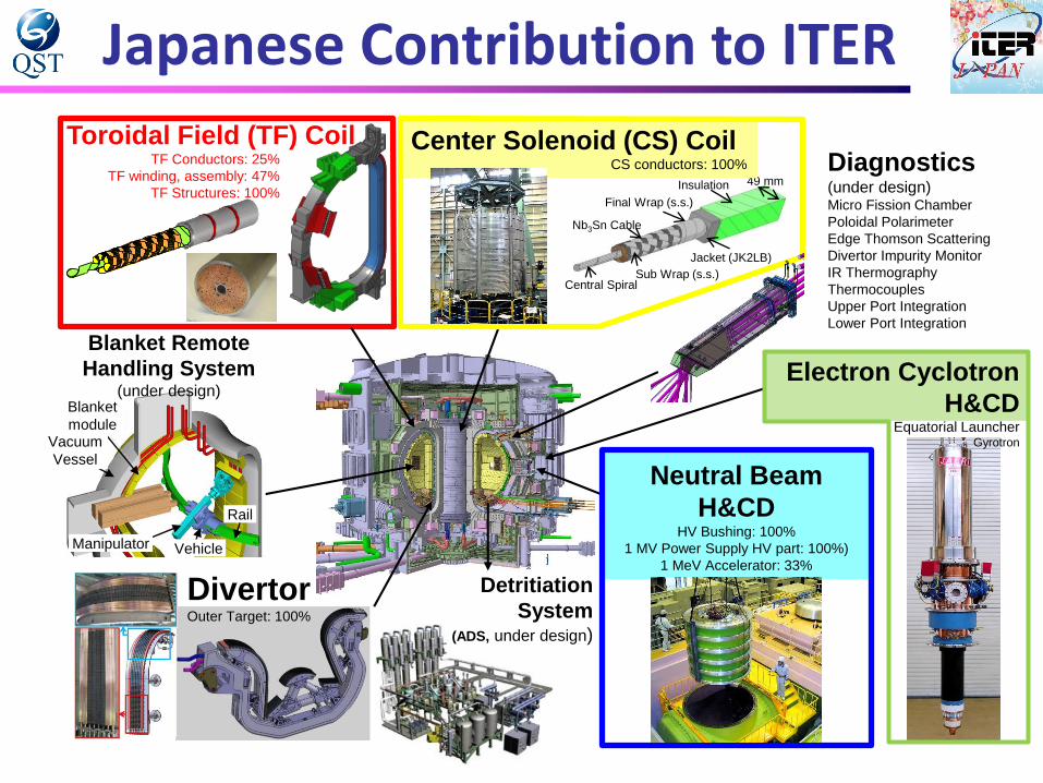
JADA has signed 12 PAs, corresponding to about 88% in credit value out of total Japanese contribution to the ITER in-kind procurement.
2007 2008 2009 2010 2011 2012 2013 2014 2015 2016
2007 2008 2009 2010 2011 2012 2013 2014 2015 2016
50
(%)100
88%*) PA
Concluded
ITER Agreement
JADA assignment
Divertor
outer target
Blanket remote handling
NB H&CD (NBTF PS,HV bushing)
Diagnostics (MFC)
TF conductor
TF coil winding & assembly,
TF structure
CS conductor
TBD
・NB H&CD
・EC H&CD
・Diagnostics
*) in “ITER unit of account” on a
basis of cost estimate done in 2001
EC H&CD (Gyrotron)
Diagnostics (Popola, ETS, DIM,
IR Th)
TF structure
ADS
Coil windingBent conductor inserted
in grooves of RPStack of 7 DPs with insulation
Double Pancake (DP)Winding
Pack (WP)Radial Plate (RP)
14 m
9 m
Structure (coil case)Integration WP and Case
Winding Pack
Coil case
Coil case
Case closed by welding, epoxy impregnation
Subassembly
TF coil
AssemblyForged/Rolled material
TF Coil Manufacturing
JacketingConductor
Conductorφ0
.82
mm
CableStrand
Twisting and cabling
Segments
BU
AU
BP
APMachining
welding
33 by JA/133 conductors
9 by JA/19 WPs
19 by JA/19 Coil cases
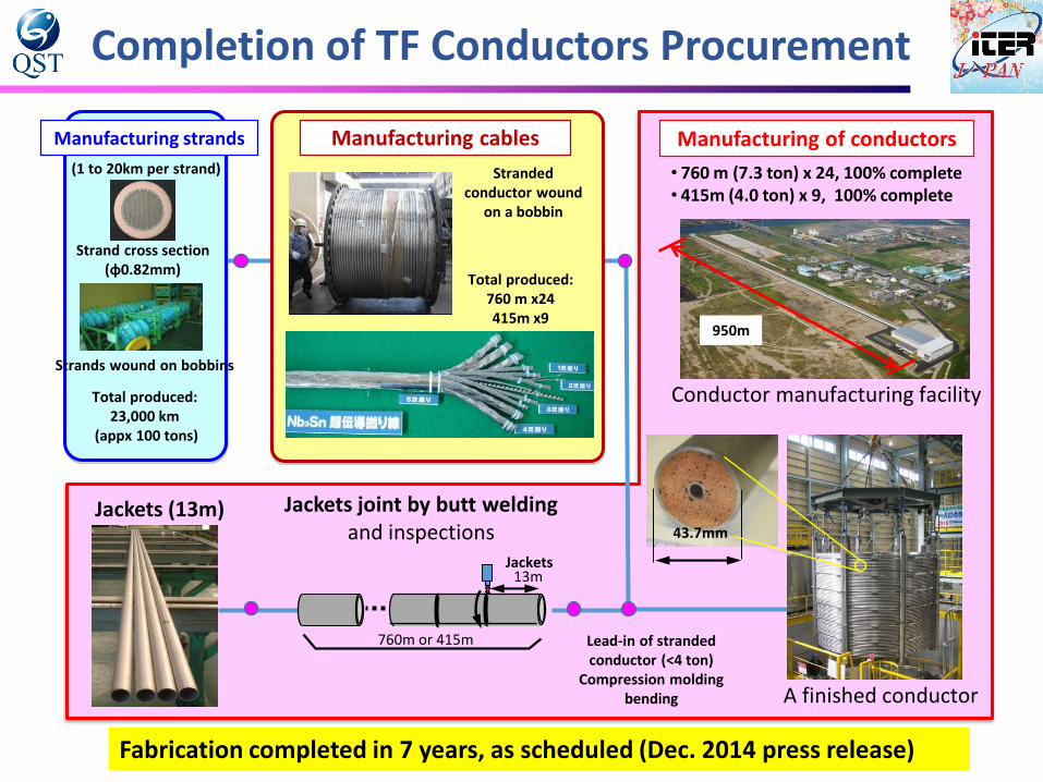
Jackets (13m)43.7mm
13m
760m or 415m
Jackets
Jackets joint by butt welding and inspections
Lead-in of stranded conductor (<4 ton)
Compression moldingbending
Manufacturing of conductors
950m
Conductor manufacturing facility
A finished conductor
• 760 m (7.3 ton) x 24, 100% complete• 415m (4.0 ton) x 9, 100% complete
Total produced:760 m x24415m x9
Manufacturing cables
Stranded conductor wound
on a bobbin
(1 to 20km per strand)
Strand cross section (φ0.82mm)
Strands wound on bobbins
Manufacturing strands
Completion of TF Conductors Procurement
Fabrication completed in 7 years, as scheduled (Dec. 2014 press release)
Total produced:23,000 km
(appx 100 tons)
TF Coil Winding process (MHI)Winding Heat Treatment
Winding
RP
Transfer
20 DPs completed,
18 DPs completed,
11 DPs completed, 10 DPs completed,
Turn Insulation
TF Coil Winding process (MHI)
DP Stacking
CP Welding DP Insulation
DP Impregnation
9 DPs completed, 7 DPs completed,
7 DPs completed, First 7 DPs stacked for TF#1 in Dec. 2016.
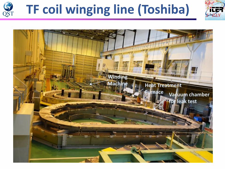
TF coil winging line (Toshiba)
Winding Machine Heat Treatment
Furnace Vacuum chamber for leak test
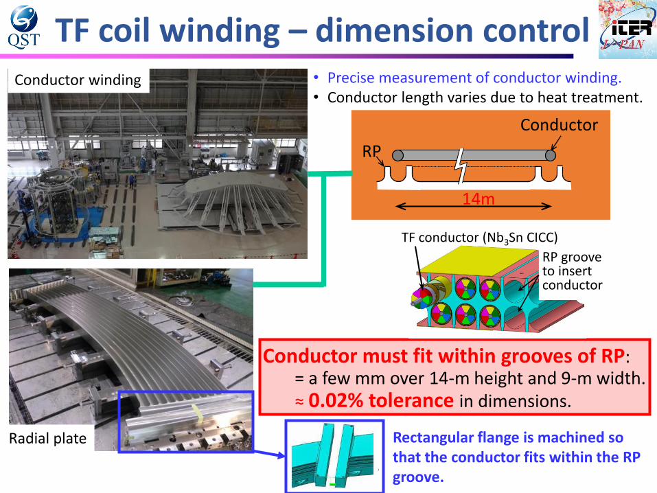
TF coil winding – dimension control
Radial plate
TF conductor (Nb3Sn CICC)
RP groove to insert conductor
Conductor must fit within grooves of RP: = a few mm over 14-m height and 9-m width.≈ 0.02% tolerance in dimensions.
Conductor
RP
14m
Conductor winding • Precise measurement of conductor winding.• Conductor length varies due to heat treatment.
Rectangular flange is machined so that the conductor fits within the RP groove.
TF Coil Structures – tight tolerance
A3
A2
A1
B1
B2
B3
B4
AP3
AP2
AP1BP4
BP1
BP2
BP3 B2 segment (HHI and Toshiba)
A3 segment (KHI) Weld joint of A2+A3segment (KHI)
A2 segment (MHI and KHI)
Welding joint of A2+A1 segment (MHI)
A1 segment (MHI)
B3 segment (Toshiba)
• Full-size prototypes have been manufactured for optimization of manufacturing technologies, such as suppression of welding deformation.
Data of welding deformation and its suppression procedures have been accumulated for fabrication of ITER TF Coils.
TF Coil Structures
Inboard Sub-assembly (consisting of 3 Basic Segments)
AP Sub-assembly
Outboard Sub-assembly
(consisting of 4 Basic Segments
before welding B1+B2 and B3+B4)
The sub-assemblies have been welded within required tolerance.
NB Test FacilityITER NB Injector
16.5 MW D0 at 1 MeV for 1 hour ITER NB system is required to generate 40 A of D- ions at 1 MeV for 3,600 s, which is much more than performance of existing NB systems (22 A, D- at 0.5 MeV for 10 s).
The ITER Council decided to build the NB test facility at Padua Italy, which has identical design to the ITER NB system, to fulfill all the requirement in advance.
Most of the 1 MV PS have been already manufactured by Hitachi Ltd.
A ceremony have been hold at Padua celebrating the arrival of Japanese components
and the start of on-site construction work, on 11th Dec. 2015.
Dignitaries including Mr. Itakura (MEXT), Mr. Bigot (DG of the ITER Organization), Mr.
Garribba (European Commission), Mr. Barabaschi (F4E), Mr. Gnezott (RFX) and Mr.
Miel (Ministry of education, Italy) were in attendance.
NBTF components shipped to Padua
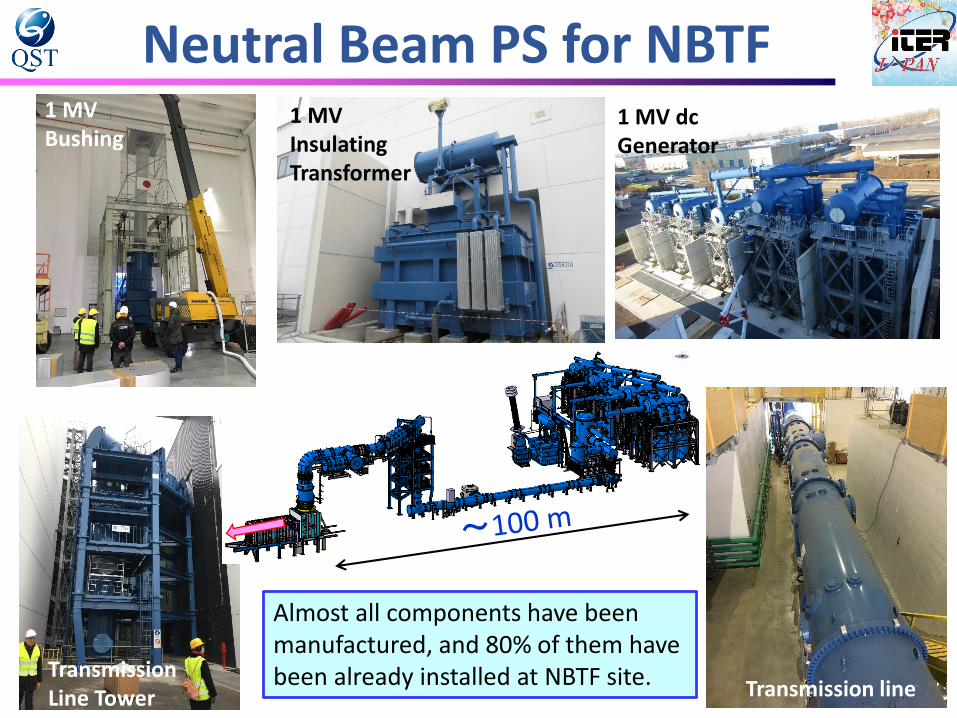
Neutral Beam PS for NBTF1 MVBushing
1 MVInsulatingTransformer
1 MV dcGenerator
Transmission lineTransmissionLine Tower
Almost all components have been manufactured, and 80% of them have been already installed at NBTF site.
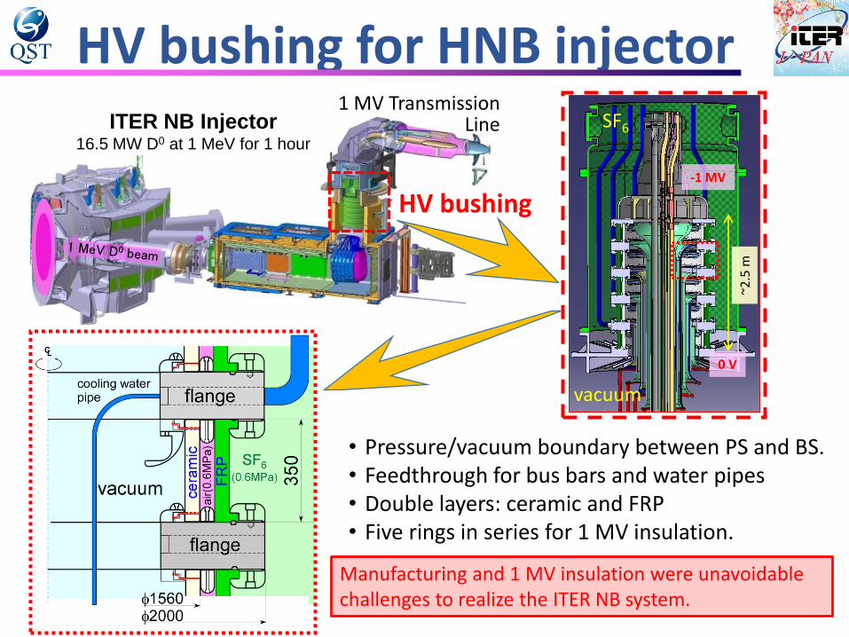
HV bushing
1 MV Transmission Line
HV bushing for HNB injector
-1 MV
~2.5
m
SF6
vacuum
0 V
ITER NB Injector16.5 MW D0 at 1 MeV for 1 hour
• Pressure/vacuum boundary between PS and BS.• Feedthrough for bus bars and water pipes• Double layers: ceramic and FRP• Five rings in series for 1 MV insulation.
Manufacturing and 1 MV insulation were unavoidable challenges to realize the ITER NB system.
Development of HV Bushing
Brazing of Kovarwith Large ceramic
f800 mm
Brazingjoint
Large bore ceramic ring R&D
Brazing R&D
0.29 m
2006
2009A half-size R&D
2005
f150 mm
Small scale R&D
3mmt Kovar
Joint R&D with Kyocera
f1.56 m
Mockup Bushing Test
Joint R&D with Hitachi Power Devices
(1) 240 kV/single stage for 2 hours (120% of rated voltage)
(2) 480 kV/two stages for 1 hour also confirmed.
Series production of ceramic rings and brazing in progress
1st 170 GHz 1 MW Gyrotron for ITER✓ Major requirement of ITER Gyrotron already achieved (1 MW for 1,000 s, efficiency
> 50%, 5 kHz modulations, etc.).✓ PA signed in Sep. 2013 (eight Gyrotrons).✓ Manufacturing of ITER Gyrotron #1 & #2 started from Jan. 2016. ✓ First Gyrotron for ITER has been delivered to QST Naka in December 2016 (on
schedule). The gyrotron is to be shipped to ITER site after high power test at Naka.
Summary• In order to manufacture the full-scale ITER components, following
challenges were required.✓ Control and precise measurement of conductor winding in D-shape and
subsequent precise machining/welding of Radial Plate,✓ Welding technologies for TF Coil Structure, to fulfill the tight tolerances
suppressing the welding deformation,✓ 1 MV insulation in air, oil and SF6 in a large capacity 1 MV dc power supply,✓ Development of large bore ceramic ring and its brazing with Kovar for HV
bushing of NB injector, together with 1 MV insulation technology in vacuum,
• First 170 GHz 1 MW Gyrotron has been delivered.• Thus Japan has developed manufacturing technology for full-scale ITER
components and their procurement is in progress together withindustries.
• For other procurements, such as Blanket Remote Handling, Diagnostics,Atmospheric Detritiation System as well as the Test Blanket System,design activities are in progress to launch manufacturing toward theITER First Plasma in 2025.