Progressive Compression for Lossless Transmission of Triangle Meshes Pierre Alliez Mathieu Desbrun † University of Southern California Abstract Lossless transmission of 3D meshes is a very challenging and timely problem for many applications, ranging from collaborative design to engineering. Additionally, frequent delays in transmis- sions call for progressive transmission in order for the end user to receive useful successive refinements of the final mesh. In this pa- per, we present a novel, fully progressive encoding approach for lossless transmission of triangle meshes with a very fine granu- larity. A new valence-driven decimating conquest, combined with patch tiling and an original strategic retriangulation is used to main- tain the regularity of valence. We demonstrate that this technique leads to good mesh quality, near-optimal connectivity encoding, and therefore a good rate-distortion ratio throughout the transmis- sion. We also improve upon previous lossless geometry encod- ing by decorrelating the normal and tangential components of the surface. For typical meshes, our method compresses connectivity down to less than 3.7 bits per vertex, 40% better in average than the best methods previously reported [5, 18]; we further reduce the usual geometry bit rates by 20% in average by exploiting the smoothness of meshes. Concretely, our technique can reduce an ascii VRML 3D model down to 1.7% of its size for a 10-bit quanti- zation (2.3% for a 12-bit quantization) while providing a very pro- gressive reconstruction. Keywords: Triangle Mesh Compression, Progressive Transmis- sion, Connectivity Encoding, Geometry Encoding, Levels of De- tails, Mesh Decimation. 1 Introduction With the growth of e-commerce and entertainment over the inter- net, the rapid transmission of 3D computer models becomes essen- tial. Both virtual shopping malls and virtual worlds require massive transmissions of triangulated 3D geometric data over the network. In this paradigm, geometry is bound to become as commonplace as text, sound, pictures, or videos. Turning a geometric object into a bit stream is therefore a very timely and relevant problem. However, signals such as sounds, pictures, or movies can rely on Fourier analysis to determine their theoretical entropy, indicating what compression ratio can be achieved. Unfortunately, in the case of a 2-manifold in 3D, we do not have any theoretical results to measure how close to the theoretical compression limit we are: sur- faces are almost impossible to analyze with the current mathemat- ical tools due to irregular valences, non-uniform sampling, and the added notion of topology. Designing a new compression algorithm is therefore all the more fundamental as it gives a better understand- ing of what is the real information content of a surface. [email protected]† [email protected]Figure 1: Our compression technique progressively transmits an arbitrary triangle mesh vertex by vertex. With (bottom) or without (top) the use of a metrics to drive the vertex ordering, we maintain good mesh quality and good rate-distortion ratio all along the transmission. Since data transmission is a transaction between a client and a server, we must take the user’s needs into account to judge the opti- mality of a compression algorithm, and not only the pure informa- tion theory side of it. An end user may not be very concerned about technical aspects like the bit rate, instead she is likely interested in getting a perceptually good geometric quality in the best time pos- sible. If the server provides data using a single-rate coding, i.e., sending serially vertex after vertex, the user cannot judge the perti- nence and quality of the information sent until the full transmission is achieved. This leads to a loss of time (and patience) on the user side, and a loss of network bandwidth for the server. The key idea to address this issue is to use progressive coding, where data are sent in a coarse-to-fine way. Optimizing the quality now equates to an optimization of the rate/distortion ratio. Concretely, progressive compression requires the transmission of a very coarse approximation first, followed by subsequent bits that allow the progressive addition of more and more details. This process will allow the user to get an early grasp of the geometry. An ideal progressive lossless coder should reach the same rate as a single-rate one when the transmission is over, with a minimal gran- ularity so that each new bit received by the decoder may be used to refine the current decoded mesh. Thus, progressive coding can be seen (again, ideally) as a simple reshuffling of the data. As recov- ering original connectivity and vertex position is very important for engineers, scientists, and for interactive collaborative design among other industrial applications, we focus on the design of a novel ap- proach to progressive, lossless encoding of arbitrary meshes to try to narrow the current significant gap in bit ratio between single-rate and progressive encoding methods. A mesh compression algorithm must compress two kinds of in- formation: the connectivity (adjacency graph of triangles) and the geometry (positions of the vertices). These two types of data are not totally independent, since the Gauss-Bonnet theorem for instance states a necessary condition between geometry and topology of a surface. However, since this condition is global, it is safe and con- venient to consider them separately. In order to present how we can optimize the compression ratios of both geometry and connectivity, we first review the previous work in this domain. 1.1 Previous Work We first briefly mention some of the single-rate coding tech- niques currently known, since they offer insight into compression
Transcript
Progressive Compression for Lossless Transmission of Triangle Meshes
Pierre Alliez � Mathieu Desbrun †
University of Southern California
AbstractLossless transmission of 3D meshes is a very challenging andtimely problem for many applications, ranging from collaborativedesign to engineering. Additionally, frequent delays in transmis-sions call for progressive transmission in order for the end user toreceive useful successive refinements of the final mesh. In this pa-per, we present a novel, fully progressive encoding approach forlossless transmission of triangle meshes with a very fine granu-larity. A new valence-driven decimating conquest, combined withpatch tiling and an original strategic retriangulation is used to main-tain the regularity of valence. We demonstrate that this techniqueleads to good mesh quality, near-optimal connectivity encoding,and therefore a good rate-distortion ratio throughout the transmis-sion. We also improve upon previous lossless geometry encod-ing by decorrelating the normal and tangential components of thesurface. For typical meshes, our method compresses connectivitydown to less than 3.7 bits per vertex, 40% better in average thanthe best methods previously reported [5, 18]; we further reducethe usual geometry bit rates by 20% in average by exploiting thesmoothness of meshes. Concretely, our technique can reduce anascii VRML 3D model down to 1.7% of its size for a 10-bit quanti-zation (2.3% for a 12-bit quantization) while providing a very pro-gressive reconstruction.
1 IntroductionWith the growth of e-commerce and entertainment over the inter-net, the rapid transmission of 3D computer models becomes essen-tial. Both virtual shopping malls and virtual worlds require massivetransmissions of triangulated 3D geometric data over the network.In this paradigm, geometry is bound to become as commonplaceas text, sound, pictures, or videos. Turning a geometric objectinto a bit stream is therefore a very timely and relevant problem.However, signals such as sounds, pictures, or movies can rely onFourier analysis to determine their theoretical entropy, indicatingwhat compression ratio can be achieved. Unfortunately, in the caseof a 2-manifold in 3D, we do not have any theoretical results tomeasure how close to the theoretical compression limit we are: sur-faces are almost impossible to analyze with the current mathemat-ical tools due to irregular valences, non-uniform sampling, and theadded notion of topology. Designing a new compression algorithmis therefore all the more fundamental as it gives a better understand-ing of what is the real information content of a surface.
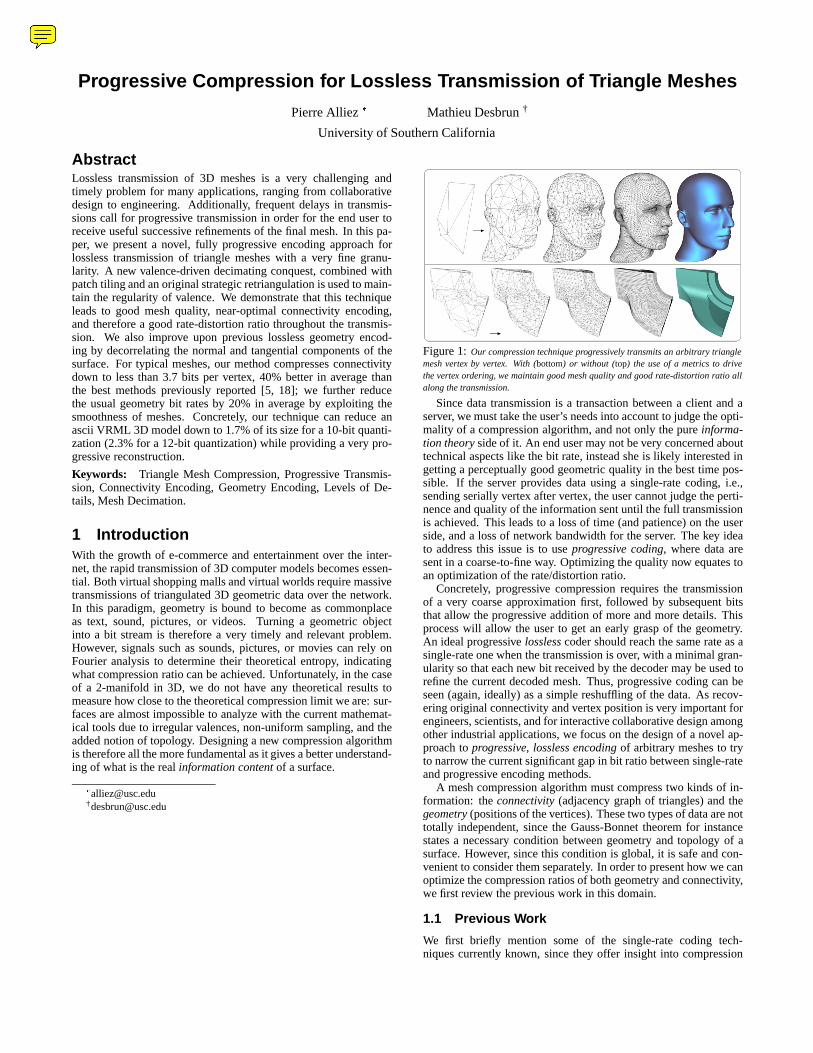
Figure 1: Our compression technique progressively transmits an arbitrary trianglemesh vertex by vertex. With (bottom) or without (top) the use of a metrics to drivethe vertex ordering, we maintain good mesh quality and good rate-distortion ratio allalong the transmission.
Since data transmission is a transaction between a client and aserver, we must take the user’s needs into account to judge the opti-mality of a compression algorithm, and not only the pure informa-tion theory side of it. An end user may not be very concerned abouttechnical aspects like the bit rate, instead she is likely interested ingetting a perceptually good geometric quality in the best time pos-sible. If the server provides data using a single-rate coding, i.e.,sending serially vertex after vertex, the user cannot judge the perti-nence and quality of the information sent until the full transmissionis achieved. This leads to a loss of time (and patience) on the userside, and a loss of network bandwidth for the server. The key ideato address this issue is to use progressive coding, where data aresent in a coarse-to-fine way. Optimizing the quality now equates toan optimization of the rate/distortion ratio.
Concretely, progressive compression requires the transmissionof a very coarse approximation first, followed by subsequent bitsthat allow the progressive addition of more and more details. Thisprocess will allow the user to get an early grasp of the geometry.An ideal progressive lossless coder should reach the same rate as asingle-rate one when the transmission is over, with a minimal gran-ularity so that each new bit received by the decoder may be used torefine the current decoded mesh. Thus, progressive coding can beseen (again, ideally) as a simple reshuffling of the data. As recov-ering original connectivity and vertex position is very important forengineers, scientists, and for interactive collaborative design amongother industrial applications, we focus on the design of a novel ap-proach to progressive, lossless encoding of arbitrary meshes to tryto narrow the current significant gap in bit ratio between single-rateand progressive encoding methods.
A mesh compression algorithm must compress two kinds of in-formation: the connectivity (adjacency graph of triangles) and thegeometry (positions of the vertices). These two types of data are nottotally independent, since the Gauss-Bonnet theorem for instancestates a necessary condition between geometry and topology of asurface. However, since this condition is global, it is safe and con-venient to consider them separately. In order to present how we canoptimize the compression ratios of both geometry and connectivity,we first review the previous work in this domain.
1.1 Previous Work
We first briefly mention some of the single-rate coding tech-niques currently known, since they offer insight into compression
Mathieu Desbrun
Note
Appeared in ACM SIGGRAPH 2001 http://www.geometry.caltech.edu/
of 3D objects. The reader can find a more detailed overview in [27].
Most of the initial mesh compression techniques use trian-gle strips as their encoding strategy [6, 2, 26], and/or vertexbuffers [10]. The EdgeBreaker algorithm [20], however, uses adifferent strategy: it turns a mesh into a sequence of five-symbolstrings using an edge conquest. Using this method a guaranteed3.67 bit/vertex rate for connectivity is presented in [14]. A veryefficient decompression of an EdgeBreaker code is introduced in[21], while a better rate for regular models is proposed in [24].
For the last three years, most papers refer (and use) the Toumaand Gotsman algorithm [28] as the best single-rate encoder in termsof compression ratio, especially for regular meshes. This techniquedefines an edge-centered conquest, creating one valence code pervertex, and some additional, yet significantly less frequent codes:dummy for boundaries, split whose frequency is closely related tomesh irregularity, and merge for genus greater than 0. The orderedlist of all valences and codes generated during the conquest arethen processed by entropy encoding. The decoder simply repro-duces the conquest according to the flow of valences sent. Thistechnique results in amazingly low bit rates on very regular meshes(valence 6 almost everywhere), since the list is basically a stringof sixes, containing almost zero entropy. Recently in [1], the samevalence-driven approach is improved upon; more importantly, en-coding only valences is proven to lead to the optimal bit rate per ver-tex for arbitrary connectivity, explaining the success of the valence-based techniques.
As for the progressive encoders, Hoppe introduces in [11] an al-gorithm for progressive transmission, starting from a coarse meshand inserting vertices one at a time. It uses the edge collapse topo-logical operator in order to decimate and record a sequence of ver-tex split encodings. The granularity is optimal, but encoding eachsplit requires log2(#v) bits both to localize the vertex to split andseveral bits to still locate its two incident edges to cut. A methodcalled Progressive Forest Split Compression is proposed by Taubinet al.in [25], using a base mesh and a forest of vertex splits. Pajarolaand Rossignac [18] group vertex-split operations into batches, thentraverse the mesh and specify splits by marking each vertex usingone bit, leading to an amortized cost of less than three bits per vertexfor the marking process. They encode the inverse edge collapse op-eration by indicating the two edges cut during the vertex split. Thegeometry is encoded using a butterfly-like prediction approach, butthe faster version of that method [19] returns to a simpler predic-tor for geometry. The connectivity of typical meshes is compresseddown to approximately 7.2 bits per vertex.
Leading to an even better bit rate, Cohen-Or et al. [5] proposeto alternate between a 2- and 4-coloring technique to decimate themesh. The choice of the coloring is driven by the distribution ofvalences in a given level of detail. The authors use vertex removaland a deterministic (or geometric) angle-driven retriangulation. Un-fortunately, the inside Z-triangulation leads to degenerate meshes,i.e. with long thin triangles. The authors try to compensate for thedegeneracy through an immediate 2-coloring pass. However, com-pared to [18], the geometric quality of the progressive mesh remainsworse. On the other hand, they achieve up to 15% better compres-sion rates. Here again, these results cannot compete with singlerate methods [28, 20] since their techniques basically increase thedispersion of valence due to the retriangulation.
For encoding the geometry, most papers use prediction, quan-tization and arithmetic coding. Khodakovsky et al. [13] point outthe great importance of normal versus tangent decomposition of therelative position for bit allocation in geometry. Devillers and Gan-doin [8] totally suppress the order of the vertices, assuming thata geometry-centered triangulation [3] is later able to progressivelyrebuild the connectivity from the regularity of the point cloud trans-mitted. Snoyeink et al. [23] and Denny and Solher [7] stress that
any data already transmitted have defined an implicit order whichcan be used to save significant entropy.
Since compression ratios and geometry quality are intricately re-lated, King and Rossignac [15] and Khodakovsky et al. [13] reallylook at 3D compression as a rate/distortion problem, rather thanfrom a pure rate viewpoint. Note that [13] obtains the best geom-etry compression ratios by far, but through a complete remeshingof the 3D surface, which is definitely the best thing to do if onlythe visual aspect of a surface needs to be transmitted. On the otherhand, we propose in this paper a lossless encoder, that will transmitan arbitrary mesh in full, yet in a progressive way.
Figure 2: Left: an optimal independent set of patches, tiling the mesh. Right: anon-optimal independent set of patches with white-colored null patches.
1.2 Overview
From the exploration of previous encoders, we make the followingsimple observations. 1) A deterministic conquest avoids an explicittransmission of order over the vertices. It implicitly builds an orderthat the coder and the decoder will agree on. If we want the ge-ometry to also be progressive, this conquest must depend uniquelyon connectivity. 2) An optimal progressive connectivity encodershould generate one valence code per vertex of the original mesh,in any order. This will achieve ”minimal” entropy as we know itfrom [1]. 3) Decimation quality and compression ratio do not seemto be mutually optimizable. Although a perfect decimation is notcrucial, care needs to be taken in order to avoid any mesh degenera-cies.
Our contributions are built upon these observations. We proposea novel method for the progressive, lossless encoding of meshes,aiming at getting as close as possible to the single-rate compres-sion ratios. We use the minimal granularity for both connectivityand geometry, i.e., we decimate (resp. insert) only one vertex at atime during the encoding (resp. decoding) phase. In a nutshell, theencoding algorithm can be roughly described in two stages:
� A valence-driven decimating conquest constructs an indepen-dent set of patches (1-rings), alternating between two verysimple strategies. Each patch center vertex is then removed,and the patch gets strategically re-triangulated to promote abalanced valence everywhere. We refer to this 2-step decima-tion as the 3-to-1 (or inverse
p3) simplification for reasons
that will be made clear in Section 3.5 (see Figure 11).
� The list of valences of the removed vertices (plus some ”cos-metic” codes) is then compressed by a code simplificationmethod that simulates the decoding process to suppress re-dundancies and a subsequent adaptive arithmetic encoder.
The remainder of this paper details this algorithm, and is articu-lated as follows: in Section 2, we give conventions and definitionsof terms we will use during the description of our algorithm in Sec-tion 3, which details the decimation strategy, the patch conquest,and the patch retriangulation. Section 4 will explain how the enduser can easily and efficiently decode the bit stream previously en-coded. We detail geometry encoding in Section 5, and give multipleresults in Section 6 to show both the quality of the hierarchy trans-mitted and the rate achieved, between 30% and 40% better thanprevious progressive encoders. We finally give conclusions in Sec-tion 7.
1 input gate(n-1) output gates
1 input gate
2 output gates
Ordinary patch (degree n) Null patchGate
front vertex
front face
v1
v2
Traversal
Gate
Face orientation
Figure 3: Left: a gate is defined by its oriented edge. Each gate stores a reference toits front face and its front vertex. Right: the gate item allows the conquest to achievethe mesh traversal through ordinary or null patches.
2 DefinitionsIn this section, we briefly describe some relevant definitions wewill use throughout this paper. When necessary, we define agraphics convention for each of these definitions to enhance theclarity of the figures.- Patch: a degree-d patch is a set of faces incident to valence-dvertex (Figure 4.A).- Vertex removal: operation consisting in removing a vertex andits incident triangles, and subsequently remeshing the remaininghole (Figures 4.B and 4.C).- Independent set: a set of patches on a mesh where each facebelongs to at most one patch. An optimal independent set isachieved when each face of the mesh belongs to exactly one patch(Figure 2.A): the patches then tile the mesh completely.- Null patch: a face that does not belong to any patch. This occurswhen a mesh is not completely tiled by the patches. Null patchesare colored in white on Figure 2.B.- Gate: an oriented edge, storing a reference to its front face (seeFigure 3). A gate allows us to go from one patch to an adjacent oneduring a mesh traversal.- State flags: each face and vertex can be tagged free, conqueredor to be removed, depending on their current state.- Retriangulation tags: each vertex can be assigned a minus or a plus � according to whether one wants to strategicallyminimize their valence or to maximize it respectively during aretriangulation. These tags are displayed on our figures when it isrequired.
A B C
Figure 4: A: a degree-5 patch. B: removal of the middle vertex. C: retriangulationof subsequent hole.
3 Progressive Connectivity EncodingIn this section, we detail the core of our progressive encoding algo-rithm. We explain how a valence-driven conquest, similar in spiritto [1], allows us to decimate a mesh layer by layer using vertex re-movals, while both maintaining a good mesh quality throughout thesimplification and guaranteeing near-optimal compression ratios.
3.1 Decimation/Coding Trade-off
Progressive transmission implies model simplification. We there-fore have to define a decimation strategy that will drive our en-coder. Decimation techniques usually need an atomic decimationoperator, an error metric, and a set of topological constraints. Inour case, the most appropriate decimation operator is vertex re-moval, since it corresponds to the finest granularity of the mesh,therefore inducing the most progressive decimation. Unfortunately,the use of error metrics in reliable decimation algorithms (for in-stance [9, 12, 17]) leads to almost random vertex removals on the
mesh. Coding the random access of such a decimation would beextremely costly compared to a single-resolution conquest [28, 1],since it requires the coding of a localization in a large set of ver-tices. Moreover, we would prefer not to rely heavily on geometry-centered decisions during the decoding process since we seek in-dependence between connectivity and geometry encoding. It thusseems that one cannot have an optimal decimation and an optimalconnectivity encoding at the same time. Our goal to obtain the bestrate/distortion ratio at any time during the transmission presents uswith a delicate tradeoff. This naturally led us to investigate whethera valence-driven decimation would be more appropriate.
3.2 Valence-driven Decimation
Importance of Low Valence Vertices
We first make the following simple observation: removing a vertexwith a valence greater than six (resp., lower than 6) from a trian-gle mesh and remeshing the subsequent hole leads to an increase(resp., a decrease) in the sum of the valences of the remaining ver-tices. This is a direct consequence of the Euler formula. If we writeV 0 the new sum of valences after one valence-v vertex removal anda local remeshing, and V the original sum of all valences excludingthis vertex, we have: V 0 =V +(v�6). Therefore, a vertex removalleads to a systematic change in valence distribution, as shown inFigure 5. Using the connectivity entropy analysis described in Sec-tion 1.1, we thus claim that removing a vertex of valence more thansix increases entropy: the data excursion of the list of valences glob-ally increases, resulting eventually in a lower compression rate. Itis therefore a bad strategy in a compression algorithm seeking thelowest bit cost.
3
77
8
6 8
6
6
5 5 6
5
656
6
6
75
6
66
7
6
5
7 5 5
7
565
7
5
84
7
Vertex removal and retriangulation
-3 0 +2
Figure 5: Influence of a vertex removal on the sum of the valences of remainingvertices: only removals of vertices with valence less than six decrease the sum of re-maining valences.
Additionally, our experiments have shown that removing a highvalence vertex often leads to two major inconveniences, indepen-dent of the error metrics chosen. First, it creates badly shaped tri-angles (even using a Z-triangulation as in [5]) if no local geometryadjustment is done after the removal, while low valence vertex re-movals are much safer. Second, a large valence vertex removal ismore likely to violate the manifold property or to change the topol-ogy of the surface. We thus strongly advocate, as already donein [7], for the removal of the vertices of valence� 6 (� 4 on bound-aries) since it maintains a low statistical valence dispersion aroundthe average value 6. Such a simple decimation strategy providesan appropriate trade-off between mesh quality and valence excur-sion. However, we need to deal with a few topology and geometryconstraints to ensure good decimation.
Safety Conditions for Vertex Removal
A vertex removal can safely be performed only if it does not violatethe manifold property of the surface. However, to make our methodmore flexible, we let the user select other types of conditions that
may be desirable. Among the vertices of valence � 6 encounteredduring the conquest and potentially removable, we forbid:
� vertices whose removal leads to violation of the manifoldproperty of the mesh, i.e. when the corresponding remesh-ing process would create already existing edges.
� vertices whose removal leads to a normal flipping locally; welet the user enable or disable this option according to the de-sired tradeoff between quality and compression rates, sincethe normal flipping is not an issue for the encoder, but may beone for the user.
� vertices violating any metrics-related decision designed by theuser; simply put, one can decide at any point if a vertex can beremoved or not in order to tune the quality of the progressivity.In essence, the decimation algorithm is open to any metricsthat would make a better rate/distortion tradeoff for a givenapplication. As mentioned before, this flexibility in qualitywill obviously result in an additional bit cost.
This valence-driven decimation is very flexible, since any or noerror metrics can be used. To prove that using only the valence issafe even without error metrics, all the examples in this paper (ex-cept for the fandisk on Figure 1, bottom) do not use any other errormetric other than a decimation purely driven by valence. Figure 1(top) illustrates such a decimation down to an eight-vertex polyhe-dron.
For objects with specific geometric characteristics like sharpedges, a geometry-driven decimation can substantially improve theperceptual rate-distortion dramatically. As we mentioned, one canskip some important vertices by just sending null patch codes ifthese particular vertices may better remain present at this stage.We designed a very simple metrics-based decimation mode whereeach vertex is first checked for validity. We experimented with twometrics-based tests: one based on a vertex-to-patch distance, andone based on the volume embedded between a patch and its retri-angulated version (and the area change for boundaries) as depictedin Figure 6. The latter is similar in spirit to [17], except that we usea binary decision for each vertex removal. We normalize the vol-ume error as following: error = 3
p(volume)=(perimeter=degree)
so that the same threshold can be used for all the scales. Figure 1(bottom) shows an example of the fandisk mesh decimation usingthe volume-based metric and a threshold parameter set to 0:25.
volumevertex-to-patchdistance
area change
removed vertex (valence 4)
removed vertex (valence 3) valence 3
Volume-based metric(ordinary case)
Distance-based metric(ordinary case)
Surface-based metric(boundary case)
perimeter
perimeter
boundary
Figure 6: Left: the vertex-to-patch distance, normalized by the patch perimeter, is apossible error metric. Middle: Better results can be achieved by an error metric definedby the volume included between the original patch and the retriangulated one, stillnormalized by the patch perimeter. Right: the area change error metric is computedfor a boundary vertex.
3.3 Overview of the Algorithm
Now that our notion of decimation is selected, we can describe theoutline of the encoding algorithm. The key idea is that in an ori-entable manifold, faces incident to a vertex can be ordered. Con-sidering an arbitrary set of patches, any vertex removal followedby a local retriangulation of the patch leaves the patch borders un-changed (see Figure 4). Therefore, these borders can be known by
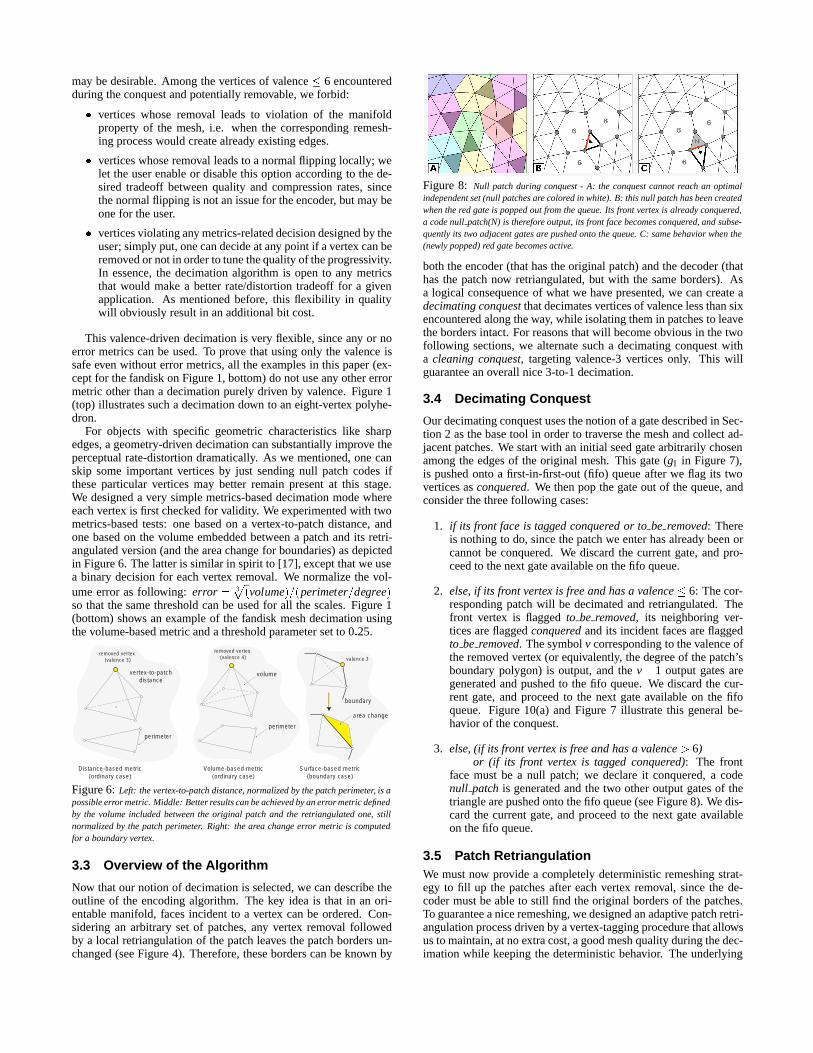
Figure 8: Null patch during conquest - A: the conquest cannot reach an optimalindependent set (null patches are colored in white). B: this null patch has been createdwhen the red gate is popped out from the queue. Its front vertex is already conquered,a code null patch(N) is therefore output, its front face becomes conquered, and subse-quently its two adjacent gates are pushed onto the queue. C: same behavior when the(newly popped) red gate becomes active.
both the encoder (that has the original patch) and the decoder (thathas the patch now retriangulated, but with the same borders). Asa logical consequence of what we have presented, we can create adecimating conquest that decimates vertices of valence less than sixencountered along the way, while isolating them in patches to leavethe borders intact. For reasons that will become obvious in the twofollowing sections, we alternate such a decimating conquest witha cleaning conquest, targeting valence-3 vertices only. This willguarantee an overall nice 3-to-1 decimation.
3.4 Decimating Conquest
Our decimating conquest uses the notion of a gate described in Sec-tion 2 as the base tool in order to traverse the mesh and collect ad-jacent patches. We start with an initial seed gate arbitrarily chosenamong the edges of the original mesh. This gate (g1 in Figure 7),is pushed onto a first-in-first-out (fifo) queue after we flag its twovertices as conquered. We then pop the gate out of the queue, andconsider the three following cases:
1. if its front face is tagged conquered or to be removed: Thereis nothing to do, since the patch we enter has already been orcannot be conquered. We discard the current gate, and pro-ceed to the next gate available on the fifo queue.
2. else, if its front vertex is free and has a valence � 6: The cor-responding patch will be decimated and retriangulated. Thefront vertex is flagged to be removed, its neighboring ver-tices are flagged conquered and its incident faces are flaggedto be removed. The symbol v corresponding to the valence ofthe removed vertex (or equivalently, the degree of the patch’sboundary polygon) is output, and the v� 1 output gates aregenerated and pushed to the fifo queue. We discard the cur-rent gate, and proceed to the next gate available on the fifoqueue. Figure 10(a) and Figure 7 illustrate this general be-havior of the conquest.
3. else, (if its front vertex is free and has a valence > 6)or (if its front vertex is tagged conquered): The front
face must be a null patch; we declare it conquered, a codenull patch is generated and the two other output gates of thetriangle are pushed onto the fifo queue (see Figure 8). We dis-card the current gate, and proceed to the next gate availableon the fifo queue.
3.5 Patch RetriangulationWe must now provide a completely deterministic remeshing strat-egy to fill up the patches after each vertex removal, since the de-coder must be able to still find the original borders of the patches.To guarantee a nice remeshing, we designed an adaptive patch retri-angulation process driven by a vertex-tagging procedure that allowsus to maintain, at no extra cost, a good mesh quality during the dec-imation while keeping the deterministic behavior. The underlying
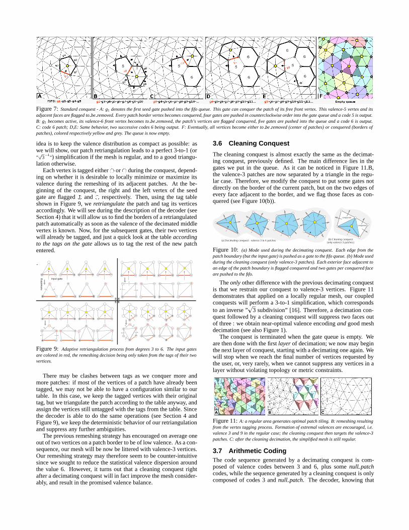
Figure 7: Standard conquest - A: g1 denotes the first seed gate pushed into the fifo queue. This gate can conquer the patch of its free front vertex. This valence-5 vertex and itsadjacent faces are flagged to be removed. Every patch border vertex becomes conquered, four gates are pushed in counterclockwise order into the gate queue and a code 5 is output.B: g2 becomes active, its valence-6 front vertex becomes to be removed, the patch’s vertices are flagged conquered, five gates are pushed into the queue and a code 6 is output.C: code 6 patch; D,E: Same behavior, two successive codes 6 being output. F: Eventually, all vertices become either to be removed (center of patches) or conquered (borders ofpatches), colored respectively yellow and grey. The queue is now empty.
idea is to keep the valence distribution as compact as possible: aswe will show, our patch retriangulation leads to a perfect 3-to-1 (or”p
3�1
”) simplification if the mesh is regular, and to a good triangu-lation otherwise.
Each vertex is tagged either or� during the conquest, depend-ing on whether it is desirable to locally minimize or maximize itsvalence during the remeshing of its adjacent patches. At the be-ginning of the conquest, the right and the left vertex of the seedgate are flagged � and respectively. Then, using the tag tableshown in Figure 9, we retriangulate the patch and tag its verticesaccordingly. We will see during the description of the decoder (seeSection 4) that it will allow us to find the borders of a retriangulatedpatch automatically as soon as the valence of the decimated middlevertex is known. Now, for the subsequent gates, their two verticeswill already be tagged, and just a quick look at the table accordingto the tags on the gate allows us to tag the rest of the new patchentered.
3 45 6
input gate
rem
eshi
ng
Figure 9: Adaptive retriangulation process from degrees 3 to 6. The input gatesare colored in red, the remeshing decision being only taken from the tags of their twovertices.
There may be clashes between tags as we conquer more andmore patches: if most of the vertices of a patch have already beentagged, we may not be able to have a configuration similar to ourtable. In this case, we keep the tagged vertices with their originaltag, but we triangulate the patch according to the table anyway, andassign the vertices still untagged with the tags from the table. Sincethe decoder is able to do the same operations (see Section 4 andFigure 9), we keep the deterministic behavior of our retriangulationand suppress any further ambiguities.
The previous remeshing strategy has encouraged on average oneout of two vertices on a patch border to be of low valence. As a con-sequence, our mesh will be now be littered with valence-3 vertices.Our remeshing strategy may therefore seem to be counter-intuitivesince we sought to reduce the statistical valence dispersion aroundthe value 6. However, it turns out that a cleaning conquest rightafter a decimating conquest will in fact improve the mesh consider-ably, and result in the promised valence balance.
3.6 Cleaning Conquest
The cleaning conquest is almost exactly the same as the decimat-ing conquest, previously defined. The main difference lies in thegates we put in the queue. As it can be noticed in Figure 11.B,the valence-3 patches are now separated by a triangle in the regu-lar case. Therefore, we modify the conquest to put some gates notdirectly on the border of the current patch, but on the two edges ofevery face adjacent to the border, and we flag those faces as con-quered (see Figure 10(b)).
Figure 10: (a) Mode used during the decimating conquest. Each edge from thepatch boundary (but the input gate) is pushed as a gate to the fifo queue. (b) Mode usedduring the cleaning conquest (only valence-3 patches). Each exterior face adjacent toan edge of the patch boundary is flagged conquered and two gates per conquered faceare pushed to the fifo.
The only other difference with the previous decimating conquestis that we restrain our conquest to valence-3 vertices. Figure 11demonstrates that applied on a locally regular mesh, our coupledconquests will perform a 3-to-1 simplification, which correspondsto an inverse ”
p3 subdivision” [16]. Therefore, a decimation con-
quest followed by a cleaning conquest will suppress two faces outof three : we obtain near-optimal valence encoding and good meshdecimation (see also Figure 1).
The conquest is terminated when the gate queue is empty. Weare then done with the first layer of decimation; we now may beginthe next layer of conquest, starting with a decimating one again. Wewill stop when we reach the final number of vertices requested bythe user, or, very rarely, when we cannot suppress any vertices in alayer without violating topology or metric constraints.
Figure 11: A: a regular area generates optimal patch tiling. B: remeshing resultingfrom the vertex tagging process. Formation of extremal valences are encouraged, i.e.valence 3 and 9 in the regular case; the cleaning conquest then targets the valence-3patches. C: after the cleaning decimation, the simplified mesh is still regular.
3.7 Arithmetic CodingThe code sequence generated by a decimating conquest is com-posed of valence codes between 3 and 6, plus some null patchcodes, while the sequence generated by a cleaning conquest is onlycomposed of codes 3 and null patch. The decoder, knowing that
we alternate between decimating and cleaning conquests, can sys-tematically replace a 3 code by a 6 code for cleaning odd layers.Indeed, during the decimating conquest, we try to minimize the va-lence of every other vertex (tagged ) on a patch in order to geta significant number of valence-3 vertices, which are easy to re-move safely during the cleaning conquest. However, these valence-3 vertices are created only temporarily to keep our retriangulationdeterministic, but they were vertices of valence 6, hence the sub-stitution we perform. Since an arithmetic encoder is very sensitiveto the occurrence of codes, it allows us to keep the peak of occur-rence at valence 6 to optimize the compression. Note also that ourtechnique of cleaning decimation is related to the 2/4-coloring al-ternation in [5], since we alternate between two different conqueststhat, conceptually, always go by pairs too.
Since we must also reorder these codes for the decoder, we pro-ceed as follows: Let A1 be the first sequence generated by a deci-mating conquest, followed by a sequence B1 resulting from clean-ing, then A2 is the second decimating conquest followed by B2,..., and An and Bn being the two final sequences. We first sub-stitute all the 3s by 6s in B1; :::;Bn, then we feed the sequenceBn �An �Bn�1 �An�1...A2 �B1 �A1 to an order-0 adaptive arithmeticencoder [29, 22]. We point out that valence codes have not been re-ordered within a layer, only the layers themselves has been reshuf-fled. We will see in Section 4 that the decoder will then be able todecode this sequence layer by layer in the same order of conquestthan the coder did, guaranteeing synchronization and correct de-coding. Notice that for a very irregular mesh, numerous null patchcodes may impede the compression ratio. We thus naturally tried toremove every unnecessary code null patch, and found that simulat-ing a decoding stage removes on average one tenth of these accidentcodes. Since this tasks is achieved by the decoder, we describe itfurther in Section 4.2.
3.8 DiscussionWith our valence-driven decimating conquest, we generate one va-lence code per vertex optimally, as in [28, 1]. Indeed, if the meshwas very regular to start with, our global strategy will only generatecodes six (one per vertex) and the mesh after conquest will remainregular: we will obtain extremely high compression ratios, justlike [1] since we encoded exactly the same zero-entropy sequence,just reordered to create progressivity. We therefore achieved theoptimality sought for very regular meshes. Although a perfectlyregular mesh is not at all representative of typical meshes, any localregularity of a mesh will generate a 3-to-1 simplification, while theother regions will have more null patch codes. Roughly, we foundour coder to be always 25% to 40% better in compression ratio thanother progressive connectivity coders on very irregular meshes, andeasily up to 200% better on more regular meshes. We postponed thediscussion of the different results with measured rates to Section 6.
4 Progressive Connectivity DecodingThe decoder receives sequences of valence or null patch codes. Fora given layer, it refines the mesh in the same order as the conquestdecimated the vertices during the encoding process. However, wereceive the layers in reverse order, so we will start with a ”un”-cleaning conquest (we call 3-patch discovery), followed, by a ”un”-decimating conquest (called patch discovery), and we repeat. Thediscovery and the vertex insertions are synchronized through thestate of the fifo queue; thus, the decoder will also know which layerneeds to be processed, and will be able to toggle between the two-gates/one-gate modes for the patch/3-patch discovery (as was de-scribed in Section 3.5). We now detail how the patch discoveryand the vertex insertions are done from the transmitted valences ornull patch codes, and explain the principle of code packing used inour encoder.
4.1 Patch Discovery and Vertex InsertionThe decoder uses exactly the same strategy defined in the coder (seeSection 3), except for the significant difference that we now have tofind the border of a patch each time we cross a gate. Aside from thisparticular problem, the implementation is perfectly similar, with thesame flags, tags, and the same fifo queue. We therefore refer thereader to the section on coding (Section 3), and we only address thepatch border discovery.
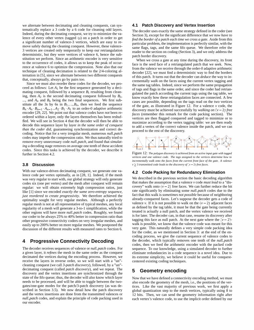
When we cross a gate at any time during the discovery, its frontface is the seed face of a retriangulated patch that we seek. Now,from the valence we receive through the order-0 adaptive arithmeticdecoder [22], we must find a deterministic way to find the bordersof this patch. It turns out that the decoder can deduce the way to in-crementally walk on the faces using the current vertex tagging andthe same tag tables. Indeed, since we perform the same propagationof tags and flags in the same order, and since the coder had retrian-gulated the patch according the current tags using the tag table, weknow exactly how these retriangulation faces are connected. A fewcases are possible, depending on the tags read on the two verticesof the gate, as illustrated in Figure 12. For a valence v code, thediscovery must be achieved successfully by walking on (v�2) freefaces (remember this remark for the code packing section). Thevertices are then flagged conquered and tagged to minimize or tomaximize according to the vertex tagging table: we are then readyto add a vertex of the correct valence inside the patch, and we canproceed to the rest of the discovery.
code 3 4 4 5 5 5 6 6
Figure 12: The polygon discovery is achieved from an active input gate with taggedvertices and one valence code. The tags assigned to the vertices determine how toincrementally walk onto the faces from the current front face of the gate. A valencev� 3 transmitted code leads to the discovery of (v�2) free faces.
4.2 Code Packing for Redundancy EliminationWe described in the previous section the basic decoding algorithmthat makes the assumption that a valence v code must lead to a ”dis-covery” walk onto (v�2) free faces. We can further reduce the bitrate significantly by eliminating some null patch codes due to thefact that this walk is sometimes not possible because of neighboringalready-conquered faces. Let’s suppose the decoder gets a code ofvalence v. If it is not possible to walk on the (v�2) adjacent facesas defined by the tag table, it must be that the gate being currentlytreated is actually a null patch, and the vertex valence we receivedis for later. The decoder can, in that case, resume its discovery aftertagging this face as null patch. At the next gate where the (v�2)-walk is possible, we know that the valence code was meant for thisvery gate. This naturally defines a very simple code packing ideafor the coder, as we mentioned in Section 3: at the end of the en-coding process, we give the current sequence of valence codes tothe decoder, which typically removes one tenth of the null patchcodes, then we feed the arithmetic encoder with the packed codesequence. To our knowledge, using a simulated decoder to furthereliminate redundancies in a code sequence is a novel idea. Due toits extreme simplicity, we believe it could be useful for conquest-centered existing coding techniques.
5 Geometry encodingNow that we have defined a connectivity encoding method, we mustalso encode the geometry of the mesh, i.e., the positions of the ver-tices. Like the vast majority of previous work, we first apply aglobal quantization step to the mesh vertices, typically using 8 to12 bits. Then, we can send the geometry information right aftereach vertex’s valence code, to use the implicit order defined by our
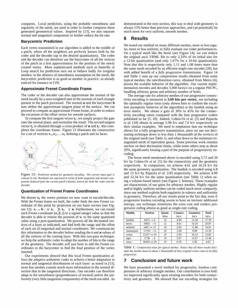
conquests. Local prediction, using the probable smoothness andregularity of the mesh, are used in order to further compress thesegenerated geometrical values. Inspired by [13], we also separatenormal and tangential components to further reduce the bit rate.
Barycentric Prediction
Each vertex transmitted in our algorithm is added in the middle ofa patch, where all the neighbors are perfectly known both by thecoder and the decoder (up to the desired quantization). The coderand the decoder can therefore use the barycenter of all the verticesof the patch as a first approximation for the position of the newlycreated vertex. More sophisticated methods such as butterfly orLoop stencil for prediction turn out to behave badly for irregularmeshes; in the absence of smoothness assumption on the mesh, thebarycentric prediction is as good as another in practice, as alreadynoticed for instance in [19].
Approximate Frenet Coordinate Frame
The coder or the decoder can also approximate the normal of themesh locally by a area-weighted sum of the normals of each trianglepresent in the patch processed. The normal n and the barycenter bnow define the approximate tangent plane of the surface. We canproceed to compute an approximate Frenet frame, in order to reducethe excursion of the offset vector for smooth surfaces.
To compute the first tangent vector t1, we simply project the gateonto the normal plane, and normalize the result. The second tangentvector t2 is obtained through a cross product of n and t1: this com-pletes the coordinate frame. Figure 13 illustrates the constructionfor a set of vertices v1;v2; :::;vn defining a patch and its faces.
input gate
Local coordinate frame
v1
v2
v3
v4v5
vr
vr
b
v6
v1
v2
v3
v4v5
b
v6
P
v1 v2
v3
v4v5
v6
vr
v1 v2
v3
v4v5 enco
ding
deco
ding
v6
b t1
t1
t2n
α
γ
β
Figure 13: Prediction method for geometry encoding. The current input gate iscolored in red. Residuals are expressed in terms of both tangential and normal com-ponents deduced from the current patch’s frontier, known for both the coder and thedecoder.
Quantization of Frenet Frame Coordinates
We denote vr the vertex position we now want to encode/decode.With the Frenet frame we built, the coder finds the new Frenet co-ordinate of this point by projection on our basis vectors (see Fig-ure 13): vr = b+α � t1 +β � t2 + γ �n: Furthermore, we can roundeach Frenet coordinate (α;β;γ) to a signed integer value so that thedecoder is able to restore the position of vr to the same quantizedvalue using a post-quantization. We process all the decimated ver-tices of a layer as indicated, and find both the range and the offsetof each set of tangential and normal coordinates. We communicatethis information to the decoder before sending the t and n values ofall the vertices of the coming layer. With this two-pass technique,we help the arithmetic coder to adapt the number of bits to the rangeof the geometry. The decoder will just have to add the Frenet co-ordinates to the barycenter to find the final position of the vertexinserted.
Our experiments showed that this local Frenet quantization al-lows the adaptive arithmetic coder to achieve a better adaptation tonormal and tangential distributions of each layer: as noted in [13],most fine meshes contain much more information in the normal di-rection that in the tangential directions. Our encoder can thereforeadapt to the smoothness (preponderance of normal) and/or the uni-formity (very little tangential components) of the mesh encoded. As
demonstrated in the next section, this way to deal with geometry isalways 15% better than previous approaches, and can potentially bemuch more for very uniform, smooth meshes.
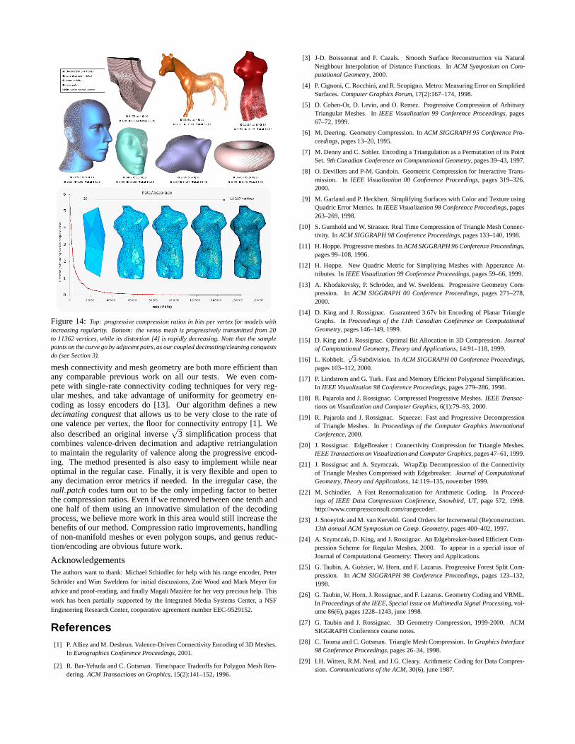
6 ResultsWe tested our method on many different meshes, more or less regu-lar, more or less uniform, to fully evaluate our coder performances.On a typical mesh like the horse (see Figure 14), we can reducethe original ascii VRML file to only 2.33% of its initial size fora 12-bit quantization (and only 1.67% for a 10-bit quantization).Note that this is respectively only 1:11 and 1:08 times more thanthe same mesh encoded by an efficient single-rate encoder [28], butwith added benefit of a fully progressive transmission. Figure 14and Table 1 sum up our compression results obtained from sometypical meshes; the rate/distortion curve, obtained from Metro [4],proves the scalable behavior of the algorithm. Our current imple-mentation encodes and decodes 5,000 faces/s on a regular PIII PC,handling arbitrary genus and arbitrary number of holes.
The average rate for arbitrary meshes of our progressive connec-tivity encoding is measured at 3.69 bits per vertex, not includingthe optimally regular torus (only shown here to confirm the excel-lent asymptotic behavior of the algorithm) or the fandisk using anerror metric. We obtain a gain of 30% to 45% for the connec-tivity encoding ratios compared with the best progressive coderspublished so far [5, 18]. Indeed, Cohen-Or et al. [5] and Pajarolaet al. [18] obtain in average 5.98 b/v and 7.0 b/v respectively ontheir similar examples. We need to emphasize that our techniqueallows for a fully progressive transmission, since we use our deci-mating technique down to less than 1 thousandth of the vertices ofthe original mesh (see Table 1), and often down to the minimum tri-angulated mesh of equivalent genus. Some previous work remainsunclear on their decimation limits, while some others stop at about20%, significantly loosing a part of the purpose of progressivity en-coding.
The horse mesh mentioned above is encoded using 5.72 and 20b/v by Cohen-Or et al. [5] for the connectivity and the geometryrespectively. In comparison, we achieve 4.61 and 16.24 b/v forthe same geometry quantization. The fandisk is encoded using 6.8and 15 b/v by Pajarola et al. [18] respectively. We achieve 4.99and 12.34 b/v for the same quantization (see Table 1) when us-ing a volume-based metric (see Figure 1, bottom). These examplesare characteristic of our gains for arbitrary meshes. Highly regularand/or highly uniform meshes can be coded much more compactly,since our method exploits both regularity in valence and uniformityin geometry. Therefore, all our results point to the fact that, even ifprogressive lossless encoding seems to have an intrinsic additionalentropy, our technique minimizes the extra cost and renders pro-gressive coding almost as good as single-rate coding.
Table 1: Compression rates for typical meshes. Notice that all these results deci-mate the meshes down to about 1 thousandth of their original vertex count to be fullyprogressive.
7 Conclusion and future workWe have presented a novel method for progressive, lossless com-pression of arbitrary triangle meshes. Our contribution is two-fold:we improved significantly upon existing encoders for both connec-tivity and geometry. We showed that our encoding strategies for
Figure 14: Top: progressive compression ratios in bits per vertex for models withincreasing regularity. Bottom: the venus mesh is progressively transmitted from 20to 11362 vertices, while its distortion [4] is rapidly decreasing. Note that the samplepoints on the curve go by adjacent pairs, as our coupled decimating/cleaning conquestsdo (see Section 3).
mesh connectivity and mesh geometry are both more efficient thanany comparable previous work on all our tests. We even com-pete with single-rate connectivity coding techniques for very reg-ular meshes, and take advantage of uniformity for geometry en-coding as lossy encoders do [13]. Our algorithm defines a newdecimating conquest that allows us to be very close to the rate ofone valence per vertex, the floor for connectivity entropy [1]. Wealso described an original inverse
p3 simplification process that
combines valence-driven decimation and adaptive retriangulationto maintain the regularity of valence along the progressive encod-ing. The method presented is also easy to implement while nearoptimal in the regular case. Finally, it is very flexible and open toany decimation error metrics if needed. In the irregular case, thenull patch codes turn out to be the only impeding factor to betterthe compression ratios. Even if we removed between one tenth andone half of them using an innovative simulation of the decodingprocess, we believe more work in this area would still increase thebenefits of our method. Compression ratio improvements, handlingof non-manifold meshes or even polygon soups, and genus reduc-tion/encoding are obvious future work.
AcknowledgementsThe authors want to thank: Michael Schindler for help with his range encoder, Peter
Schroder and Wim Sweldens for initial discussions, Zoe Wood and Mark Meyer for
advice and proof-reading, and finally Magali Maziere for her very precious help. This
work has been partially supported by the Integrated Media Systems Center, a NSF
Engineering Research Center, cooperative agreement number EEC-9529152.
References[1] P. Alliez and M. Desbrun. Valence-Driven Connectivity Encoding of 3D Meshes.
In Eurographics Conference Proceedings, 2001.
[2] R. Bar-Yehuda and C. Gotsman. Time/space Tradeoffs for Polygon Mesh Ren-dering. ACM Transactions on Graphics, 15(2):141–152, 1996.
[3] J-D. Boissonnat and F. Cazals. Smooth Surface Reconstruction via NaturalNeighbour Interpolation of Distance Functions. In ACM Symposium on Com-putational Geometry, 2000.
[4] P. Cignoni, C. Rocchini, and R. Scopigno. Metro: Measuring Error on SimplifiedSurfaces. Computer Graphics Forum, 17(2):167–174, 1998.
[5] D. Cohen-Or, D. Levin, and O. Remez. Progressive Compression of ArbitraryTriangular Meshes. In IEEE Visualization 99 Conference Proceedings, pages67–72, 1999.
[6] M. Deering. Geometry Compression. In ACM SIGGRAPH 95 Conference Pro-ceedings, pages 13–20, 1995.
[7] M. Denny and C. Sohler. Encoding a Triangulation as a Permutation of its PointSet. 9th Canadian Conference on Computational Geometry, pages 39–43, 1997.
[8] O. Devillers and P-M. Gandoin. Geometric Compression for Interactive Trans-mission. In IEEE Visualization 00 Conference Proceedings, pages 319–326,2000.
[9] M. Garland and P. Heckbert. Simplifying Surfaces with Color and Texture usingQuadric Error Metrics. In IEEE Visualization 98 Conference Proceedings, pages263–269, 1998.
[10] S. Gumhold and W. Strasser. Real Time Compression of Triangle Mesh Connec-tivity. In ACM SIGGRAPH 98 Conference Proceedings, pages 133–140, 1998.
[11] H. Hoppe. Progressive meshes. In ACM SIGGRAPH 96 Conference Proceedings,pages 99–108, 1996.
[12] H. Hoppe. New Quadric Metric for Simpliying Meshes with Apperance At-tributes. In IEEE Visualization 99 Conference Proceedings, pages 59–66, 1999.
[13] A. Khodakovsky, P. Schroder, and W. Sweldens. Progressive Geometry Com-pression. In ACM SIGGRAPH 00 Conference Proceedings, pages 271–278,2000.
[14] D. King and J. Rossignac. Guaranteed 3.67v bit Encoding of Planar TriangleGraphs. In Proceedings of the 11th Canadian Conference on ComputationalGeometry, pages 146–149, 1999.
[15] D. King and J. Rossignac. Optimal Bit Allocation in 3D Compression. Journalof Computational Geometry, Theory and Applications, 14:91–118, 1999.
[16] L. Kobbelt.p
3-Subdivision. In ACM SIGGRAPH 00 Conference Proceedings,pages 103–112, 2000.
[17] P. Lindstrom and G. Turk. Fast and Memory Efficient Polygonal Simplification.In IEEE Visualization 98 Conference Proceedings, pages 279–286, 1998.
[18] R. Pajarola and J. Rossignac. Compressed Progressive Meshes. IEEE Transac-tions on Visualization and Computer Graphics, 6(1):79–93, 2000.
[19] R. Pajarola and J. Rossignac. Squeeze: Fast and Progressive Decompressionof Triangle Meshes. In Proceedings of the Computer Graphics InternationalConference, 2000.
[20] J. Rossignac. EdgeBreaker : Connectivity Compression for Triangle Meshes.IEEE Transactions on Visualization and Computer Graphics, pages 47–61, 1999.
[21] J. Rossignac and A. Szymczak. WrapZip Decompression of the Connectivityof Triangle Meshes Compressed with Edgebreaker. Journal of ComputationalGeometry, Theory and Applications, 14:119–135, november 1999.
[22] M. Schindler. A Fast Renormalization for Arithmetic Coding. In Proceed-ings of IEEE Data Compression Conference, Snowbird, UT, page 572, 1998.http://www.compressconsult.com/rangecoder/.
[23] J. Snoeyink and M. van Kerveld. Good Orders for Incremental (Re)construction.13th annual ACM Symposium on Comp. Geometry, pages 400–402, 1997.
[24] A. Szymczak, D. King, and J. Rossignac. An Edgebreaker-based Efficient Com-pression Scheme for Regular Meshes, 2000. To appear in a special issue ofJournal of Computational Geometry: Theory and Applications.
[25] G. Taubin, A. Gueziec, W. Horn, and F. Lazarus. Progressive Forest Split Com-pression. In ACM SIGGRAPH 98 Conference Proceedings, pages 123–132,1998.
[26] G. Taubin, W. Horn, J. Rossignac, and F. Lazarus. Geometry Coding and VRML.In Proceedings of the IEEE, Special issue on Multimedia Signal Processing, vol-ume 86(6), pages 1228–1243, june 1998.
[27] G. Taubin and J. Rossignac. 3D Geometry Compression, 1999-2000. ACMSIGGRAPH Conference course notes.
[28] C. Touma and C. Gotsman. Triangle Mesh Compression. In Graphics Interface98 Conference Proceedings, pages 26–34, 1998.
[29] I.H. Witten, R.M. Neal, and J.G. Cleary. Arithmetic Coding for Data Compres-sion. Communications of the ACM, 30(6), june 1987.